Revised: 3-Jun-10
DataSat II
SkyEdge IP and Pro Installation and Monitoring
Version 052006
2 / 40
1. Introduction and Overview ………………………………………………………………………………..7
1.1 Background and Purpose …………………………………………………………………………….7
1.2 SkyEdge VSAT Expansion Cards ………………………………………………………………….10
1.3 LCD Display and Keypad……………………………………………………………………………..11
1.4 Inter-Facility Link (IFL) Cables………………………………………………………………………12
1.4.1 Coaxial Cables………………………………………………………………………………….12
1.4.2 LAN Cable ……………………………………………………………………………………….12
2. Configuring the VSAT ……………………………………………………………………………………….13
2.1 Data Required ……………………………………………………………………………………………13
2.2 Configuring the VSAT via the LCD Keypad……………………………………………………..14
2.3 Configuring SkyEdge VSATs via SkyManage Web Page …………………………………15
2.3.1 Accessing the SkyManage Web Page …………………………………………………15
2.3.2 Configuring the VSAT……………………………………………………………………….20
2.4 Configuring a VSAT using a File ………………………………………………………………….23
2.4.1 Saving the Configuration as a File………………………………………………………23
2.4.2 Uploading a File to a VSAT ……………………………………………………………….25
2.4.3 Modifying VSAT Parameters ……………………………………………………………..25
2.5 Reset VSAT……………………………………………………………………………………………..25
3. VSAT Installation ……………………………………………………………………………………………27
3.1 Grounding ……………………………………………………………………………………………….27
3.2 VSAT Physical Connections ……………………………………………………………………….28
3.3 Mesh VSAT Physical Connections……………………………………………………………….29
3.4 Using the VSAT as a Pointing Device …………………………………………………………..30
3.5 Initial Boot-Up…………………………………………………………………………………………..32
3.5.1 Monitoring via the LCDs ……………………………………………………………………32
3.5.2 Monitoring via the SkyManage Web Page ……………………………………………33
3.6 Activating CW…………………………………………………………………………………………..36
3.6.1 Activating CW from the LCD Keypad…………………………………………………..36
3.6.2 Activating CW from the SkyManage Web Page …………………………………….38
4. VSAT Monitoring and Troubleshooting …………………………………………………………….39
4.1 Using LCD Display ……………………………………………………………………………………39
4.2 Monitoring Using SkyManage Web Page ………………………………………………………40
3 / 40
Figure 1: SkyEdge Pro VSAT (front view) …………………………………………………………….. 7
Figure 2: SkyEdge IP VSAT (front view) ………………………………………………………………. 7
Figure 3: SkyEdge IP VSAT Version 3 (front view) ………………………………………………… 7
Figure 4: SkyEdge Call VSAT (front view) ……………………………………………………………. 8
Figure 5: SkyEdge Pro VSAT (rear view) ……………………………………………………………… 8
Figure 6: SkyEdge IP VSAT (rear view) ……………………………………………………………….. 8
Figure 7: SkyEdge IP VSAT with External Power Supply (rear view) ………………………… 9
Figure 8: SkyEdge IP VSAT Version 3 (rear view) …………………………………………………. 9
Figure 9: SkyEdge Call VSAT (AC type rear view)…………………………………………………. 9
Figure 10: SkyEdge Call VSAT (DC type rear view)……………………………………………….. 9
Figure 11: Mesh Card with RF Splitter …………………………………………………………………. 11
Figure 12: LCD Display and Keypad ……………………………………………………………………. 11
Figure 13: SkyManage Home Page …………………………………………………………………… 17
Figure 14: Info Page Before Configuration………………………………………………………….. 18
Figure 15: Telemetry Page ………………………………………………………………………………. 19
Figure 16: CPU Utilization Graph………………………………………………………………………. 19
Figure 17: Password……………………………………………………………………………………….. 20
Figure 18: Setup…………………………………………………………………………………………….. 20
Figure 19: Configuration Parameters …………………………………………………………………. 21
Figure 20: Confirm Configuration Parameters……………………………………………………… 22
Figure 21: Submit Successful …………………………………………………………………………… 23
Figure 22: Setup from file ………………………………………………………………………………… 24
Figure 23: Save as file…………………………………………………………………………………….. 24
Figure 24: Setup file ……………………………………………………………………………………….. 25
Figure 25: Reset VSAT……………………………………………………………………………………. 26
Figure 26: Confirm Reset VSAT………………………………………………………………………… 26
Figure 27: Reset VSAT Successful ……………………………………………………………………. 26
Figure 28: SkyEdge IP VSAT – Grounding Pin ……………………………………………………. 27
Figure 29: SkyEdge Pro VSAT – Grounding Pin ………………………………………………….. 27
Figure 30: ODU and Cable Connections …………………………………………………………….. 28
Figure 31: Mesh VSAT Physical Connections ……………………………………………………… 29
Figure 32: Antenna …………………………………………………………………………………………. 31
Figure 33: VSAT LEDs ……………………………………………………………………………………. 32
Figure 34: Boot Code and Outbound Locked ………………………………………………………. 33
Figure 35: Download Software………………………………………………………………………….. 33
Figure 36: Outbound Locked in Operational Code ……………………………………………….. 34
Figure 37: VSAT Authenticated with Sync and Satellite Link Up …………………………….. 34
Figure 38: Access Scheme Defined …………………………………………………………………… 35
Figure 39: Active VSAT …………………………………………………………………………………… 35
Figure 40: VSAT Info page for Active VSAT………………………………………………………… 36
Figure 41: CW Off…………………………………………………………………………………………… 38
Figure 42: CW On…………………………………………………………………………………………… 38
4 / 40
Table 1: VSAT Types and Plug-in Cards. ……………………………………………………………..10
Table 2: Keypad Functions………………………………………………………………………………….12
Table 3: VSAT Installation Parameters………………………………………………………………….13
Table 4: Configuration Parameters……………………………………………………………………….22
Table 5: LED Boot Sequence ……………………………………………………………………………..32
Table 6: VSAT Monitoring Menus…………………………………………………………………………39
5 / 40
About This Manual
This section describes the objectives, audience, document layout and conventions of the SkyEdge
VSAT Installation and Monitoring manual.
Objectives
This manual provides detailed instructions how to configure, install and monitor the operation of the SkyEdge Pro, IP, Call or Gateway VSAT.
How to Use This Manual
This manual is to be used by a trained installer in order to configure and install a VSAT. The stepby-step procedures are to be closely followed in order to ensure that he configuration and installation will be successful.
Audience
This manual is designed for trained personnel who will be responsible for the configuration, installation and monitoring of VSATs in a SkyEdge network.
Organization
The table below contains a list of the chapters in the manual, the chapter titles and a short description of the material contained in each chapter.
Chapter Chapter Title Description
Chapter 1
Chapter 2
Chapter 3
Chapter 4
Introduction and Overview
Configuring the VSAT
VSAT Installation
VSAT Monitoring and Troubleshooting
Contains a brief description of the VSAAT and its
LCD keypad that is used for configuration
Contains details instructions on how to configure the VSAT using the LCD keypad or the
SkyManage web page
Instructs how to connect and boot-up a VSAT to a previously pointed antenna and how to ground the
VSAT. Shows how to use the VSAT as a pointing device. Contains instructions on how to broadcast a CW from the VSAT
Describes the menus and their parameters that are shown when the VSAT is in operation. These can be helpful in troubleshooting the VSAT operations.
Boldface font
Italic font
Screen font
6 / 40
Conventions
This manual uses the following conventions to convey instructions and information:
Convention Description
Commands and keywords
The result of an instruction or command
Information to be typed into a form or dialog
7 / 40
1. Introduction and Overview
1.1 Background and Purpose
In order to enable a VSAT to come on line it has to be configured with a minimum number of parameters that are used to enable the VSAT to boot up. Currently, this operation is performed using the LCD panel and keypad located on the front of the SkyEdge Pro or IP VSATs. There is no requirement for a PC (laptop or desktop) to configure the VSAT. The SkyEdge Pro VSAT is shown in Figure 1 (front) and Figure 5 (rear). The IP VSAT is shown in Figure 2 (front) and Figure
6 (rear). The SkyEdge IP VSAT Version 3 (Figure 3) and SkyEdge Call VSAT (Figure 4) are configured using the internal web page. This procedure is found in Section 2.3.
Figure 1: SkyEdge Pro VSAT (front view)
Figure 2: SkyEdge IP VSAT (front view)
Figure 3: SkyEdge IP VSAT Version 3 (front view)
Figure 4: SkyEdge Call VSAT (front view)
8 / 40
Figure 5: SkyEdge Pro VSAT (rear view)
Figure 6: SkyEdge IP VSAT (rear view)
9 / 40
Figure 7: SkyEdge IP VSAT with External Power Supply (rear view)
Figure 8: SkyEdge IP VSAT Version 3 (rear view)
Figure 9: SkyEdge Call VSAT (AC type rear view)
Figure 10: SkyEdge Call VSAT (DC type rear view)
10 / 40
The VSAT can be in either one of two modes, Boot or Operational. The configuration parameters can only be modified while the VSAT is in Boot mode. This ensures that no changes can be made in the basis VSAT configuration parameters to a VSAT that is live in a network. All changes to such a VSAT will be made from the NMS.
1.2 SkyEdge VSAT Expansion Cards
The SkyEdge Pro and Gateway VSATS can contain expansion cards that give additional capabilities to the VSAT. The possible locations of the expansion cards are shown in Table 1.
Table 1: VSAT Types and Plug-in Cards
VSAT Type
SkyEdge IP
SkyEdge PRO
SkyEdge
Gateway
Optional Plug-in Cards Plug-in Cards Combinations and Limitations
None None
Single Line – one FXS port
Dual Line – two FXS ports
Quad Line – four FXS ports
Any combination of 1-12 FXS lines, limited by the number of available slots
Quad LAN
Serial Async/Sync
Quad LAN can be installed only in slot 3. Only one
Quad LAN card can be installed in the VSAT. When the Quad LAN card is installed, the on-board LAN is disabled.
Up to 3 cards per VSAT (3 x DB-25 interfaces per
SkyEdge Pro), limited by the number of available slots.
Dual Serial Async (DB-9)
Mesh Receiver
Up to 3 cards per VSAT (6 x DB-9 interfaces per
SkyEdge Pro), limited by the number of available slots.
Mesh Receiver can be installed only in slot 1. One card per SkyEdge Pro IDU.
Single Line – one FXS port
Dual Line – two FXS ports
Quad Line – four FXS ports
Any combination of 1-8 FXS lines, limited by the number of available slots.
E1 Interface
Serial Async/Async (DB-25)
Dual Serial Async (DB-9)
Mesh Receiver
Quad LAN
E1 interface card must be installed in a basic SkyEdge
Gateway IDU.
E1 card will always be installed in slot 2 to avoid any configuration limitations.
Up to 2 cards per VSAT (2 x DB-25 interfaces per
SkyEdge Gateway) limited by the number of available slots.
Up to 2 cards per VSAT (4 x DB-9 interfaces per
SkyEdge Gateway) limited by the number of available slots.
Mesh Receiver can be installed only in slot 1. One card per SkyEdge Pro IDU.
Quad LAN can be installed only in slot 3.
11 / 40
When a Mesh card is installed, the RF IN port on the Mesh card and the RF IN port on the VSAT are connected with an RF splitter, supplied by Gilat, as shown in Figure 11.
Figure 11: Mesh Card with RF Splitter
1.3 LCD Display and Keypad
The VSAT LCD display and keypad are shown in Figure 12
Figure 12: LCD Display and Keypad
The keypad is used to configure the VSAT in Boot mode and to navigate through the display in both Boot and Operational modes. An explanation of the functions is found in Table 2.
Operation Mode
Scroll through menu
Scroll through menu
Inactive
Inactive
Enter the sub-menu
Exit to the previous menu
12 / 40
Table 2: Keypad Functions
Key Description Boot Mode
Up Arrow ▲
Down Arrow ▼
Scroll through menu
Increase number of digits displayed
Scroll through menu
Decrease number of digit displayed
Left Arrow ◄
Right Arrow ►
Enter
Esc
Move left to next character
Move right to next character
Enter the sub-menu
Enter the displayed or selected data
Exit and save the displayed or selected data
Exit to the previous menu
Exit and ignore the displayed or selected data
1.4 Inter-Facility Link (IFL) Cables
1.4.1 Coaxial Cables
The Inter-Facility Link between the ODU and IDU provides a full duplex communication path between the two units. It consists of two coaxial cables: IFL Tx and IFL Rx. In general, no line amplification is required for cables less than 50 meters in length. For lengths over 50 meters consult your Gilat representative for additional information and specifications.
1.4.2 LAN Cable
All of the LAN cables used are type CAT-5. Ethernet hubs or switches are used to connect multiple PCs to the SkyEdge VSAT. The maximum length of a LAN cable is 100 meters (325 feet).
13 / 40
2. Configuring the VSAT
2.1 Data Required
Prior to configuring a VSAT verify that the following parameters have been supplied by the hub operations staff using the spreadsheet supplied by Gilat. The parameters are found in Table 3.
For two of the parameters (OB Modulation and OB Code Rating) a number is entered that represents a predetermined modulation or FEC rate.
Parameter
Password
OB Modulation
OB Coding Rate
ODU Initial Offset
Table 3: VSAT Installation Parameters
OB Frequency (KHz)
OB Data Rate (bps)
OB ID
DVB Reduced Latency (For telephony only)
Management PID
Workgroup ID
Software Group ID
VSAT ID
DHCP
Code Entered and Value
44528
0 – QPSK
1 – QPSK Turbo
2 – 8PSK Turbo
0 – ½
1 – ¼
2 – 2/3
3 – ¾
4 – ¾:205
5 – ¾:21
6 – ¾:26
7 – 5/6
8 – 6/7
9 – 7/8
10 – 8/9
Disabled
Enabled
1 – ON
0 — OFF
The value is obtained from the ODU. The value entered is with the opposite sign. For example; if the Initial Offset value on the ODU is 300, the value entered is – 300.
2.2 Configuring the VSAT via the LCD Keypad
14 / 40
To configure the VSAT parameters using the LCD display:
1. Verify that nothing is connected to the VSAT except for the power cable.
2. Turn the VSAT power switch to On.
Result: The VSAT PWR LED turns on and VSAT Information appears on the LCD display.
3. When the Tx LED starts blinking press Esc.
4. Press Down (▼) twice.
Result: VSAT Configuration appears on the LCD display.
5. Press Enter.
Result: PASSWORD appears on the LCD display
6. Press Enter.
Result: The first digit flashes.
7. Enter the first digit of password given by pressing the up (▲) or down (▼) arrow and press the right arrow (►).
Result: The next digit flashes.
8. Repeat step 7 until all of the digits of the password have been entered.
9. Press Enter.
Result: If the password has been entered correctly, Access Granted flashes in the
LCD display followed by CW Test.
If the password has not been entered correctly, Access Denied appears.
10. Press the down arrow (▼) and press Enter.
Result: OB Modulation appears on the LCD display
15 / 40
11. Enter the code for the Outbound Modulation from Table 3. Press Enter.
Result: Saved flashes on the LCD display.
12. Repeat Steps 10 and 11 for the following parameters:
Outbound Coding Rate
Outbound Frequency
Outbound Data Rate
Outbound ID
DVB Reduced Latency
Management PID
Workgroup ID
Software Group ID
VSAT ID
DHCP
13. Press the down arrow (▼) and press Enter. Enter the ODU Initial Offset Value found on the ODU with the opposite sign.
14. Press Enter.
At this point the VSAT configuration is complete.
2.3 Configuring SkyEdge VSATs via SkyManage Web Page
All SkyEdge VSATs can be configured via the SkyManage web page contained in the factory installed Boot Code version 2.0.3.3 or higher. SkyEdge Call VSATs and SkyEdge IP VSATs
16 / 40
Version 3 must be configured using this procedure because they do not have a keypad or LCD display.
2.3.1 Accessing the SkyManage Web Page
The SkyManage web page can be accessed in a number of different ways:
Via a PC using a cross LAN cable
Via a PC with a wireless link. A wireless adapter is inserted in the VSAT LANport.
Via a PDA (Palm type device) running Microsoft Mobile 2003 or Palm OS with PalmOne
Blazer (V4.0 or higher) web browser. Either a cross LAN cable or a wireless connection can be used.
17 / 40
1. To open the SkyManage web page type 192.168.1.1 in the address bar and click to open.
Result: The SkyManage home page opens (Figure 13).
Figure 13: SkyManage Home Page
The home page, viewable by all users, contains the following information (for an operational
VSAT additional parameters are shown):
The VSAT type is indicated by the picture in the upper right corner (Pro VSAT in this case)
The VSAT status (in this case Boot) is shown by the logo in the upper left corner
Active code type — Boot or Operational
Outbound Lock state – Unlocked or Locked
LAN Port – speed and duplex mode mode
Powering mode – Normal/Low Power/Power Save
Operation time – time since VSAT was powered on or reset
18 / 40
2. Click Info to open the page (Figure 14) showing the hardware and software components of the VSAT
Figure 14: Info Page Before Configuration
The Info page, viewable by all users, contains the following:
Identity – VSAT ID (if configured), part number and serial number (factory assigned)
Hardware – identifies the hardware version of the main board and any expansion cards present
Software – lists the factory boot version, active boot version and operation version of the
VSAT. A VSAT that has never received operational code will have a message instead of the code version.
Networking – lists the MAC address, Admin IP address and Admin subnet mask
(factory assigned)
3. Click Telemetry to view the available telemetries (Figure 15).
19 / 40
Figure 15: Telemetry Page
This page shows the CPU Utilization and Rx Signal EbN0 (for offline VSATs the value is 0).
4. To view a graphical presentation of the telemetry, click on the Graph button next to the telemetry bar graph.
Result: The CPU Utilization Graph appears (Figure 16).
2.3.2 Configuring the VSAT
To configure the VSAT from the SkyManage web site:
1. Click Installer.
Result: The Password screen opens (Figure 17).
20 / 40
Figure 17: Password
2. Type the User name inst and Password $Sat2598$ and click OK.
Result: The Setup page opens (Figure 18).
Figure 18: Setup
21 / 40
3. Enter all of the configuration parameters as shown in Figure 19 and explained in Table 4.
Figure 19: Configuration Parameters
22 / 40
Parameter Type
General
Table 4: Configuration Parameters
Parameter
VSAT ID
Workgroup Address
Software Group Address
Manage PID
Outbound ID
Software Download
Explanation
Assigned in NMS
Enable or Disable
Bott-time Options
Software Download Timeout
DHCP
ODU Constant Drift
LNB Installation
ODU Type
Needs to be entered when configuration parameters are modified to prevent VSAT from not rebooting
Enable or Disable
Value is found on ODU
Frequency
Data Rate
Modulation
Outbound Frequency
Outbound Data Rate
DVB, Advanced QPSK or
8PSK
Modulation and Coding
Coding Rate
½, 2/3, 3/4 2.05, ¾ 2.1, 5/6,
7/8, 8/9
DVB Reduced Latency (for telephony only)
Disable or Enable
4. When all of the parameters have been entered, click Submit.
Result: The confirmation message appears (Figure 20).
5. Click OK.
Figure 20: Confirm Configuration Parameters
23 / 40
Result: The Submit Successful message appears (Figure 21).
2.4 Configuring a VSAT using a File
Figure 21: Submit Successful
When multiple VSATs are configured, the changes between them are minimal. In order to simplify the configuration process, the configuration of one VSAT cab used for others using the procedure in this section. The parts of the procedure are as follows:
Save the configuration to a PC as a file
Upload the file to the VSAT to be configured
Modify the parameters as necessary (in all cases the VSAT ID must be changed
2.4.1 Saving the Configuration as a File
To save a VSAT configuration as a file:
1. After submitting the configuration, click Setup from File.
Result: The Setup from file page opens (Figure 22).
24 / 40
Figure 22: Setup from file
2. Click Save current setup parameters to file.
Result: The Save as file message appears (Figure 23).
Figure 23: Save as file
3. Click Save.
Result: A Save As dialog box opens.
4. Save the file to the desired location. It is recommended that the file be saved to the
Desktop.
A sample file is shown in Figure 24.
25 / 40
Figure 24: Setup file
2.4.2 Uploading a File to a VSAT
To upload a file to a VSAT:
1. On the Setup from file page, click Browse (Figure 22).
2. Browse to the location of the file and click Load.
Result: The parameters are loaded to the VSAT.
2.4.3 Modifying VSAT Parameters
To modify the VSAT parameters that are different from the ones in the imported file, go to Section
2.3.2 and start at step 3.
2.5 Reset VSAT
To reset a VSAT:
1. On the Installer page, click Reset.
Result: The Reset VSAT page opens (Figure 25).
26 / 40
Figure 25: Reset VSAT
2. Click Reset VSAT.
Result: The Confirm Reset VSAT message appears (Figure 25).
Figure 26: Confirm Reset VSAT
3. Click OK.
Result: The Reset VSAT Successful message appears (Figure 27).
Figure 27: Reset VSAT Successful
3. VSAT Installation
3.1 Grounding
27 / 40
To connect the VSAT to “ground”:
1. Connect one end of the grounding wire to the Grounding Pin of the VSAT
(Figure 28 for IP VSAT or Figure 29 for Pro VSAT) and tighten the bolt in order to secure the connection.
Figure 28: SkyEdge IP VSAT – Grounding Pin
Figure 29: SkyEdge Pro VSAT – Grounding Pin
2. Connect the other end of the grounding wire to the common ground, if possible, or to the nearest local grounding point (for example – a water pipe).
3.2 VSAT Physical Connections
28 / 40
To connect the VSAT to the ODU and Antenna perform the following:
1. Connect the IFL cables to the ODU as shown in Figure 30.
Figure 30: ODU and Cable Connections
2. Place the VSAT on a flat surface with the rear panel facing towards you as shown in Figure 5 for the SkyEdge Pro VSAT and Figure 6 for the SkyEdge IP VSAT.
3. Connect the coaxial cable labeled RF IN to the RF-IN connector on the VSAT.
4. Connect the cable marked RF OUT to the RF OUT connector on the VSAT.
29 / 40
5. Insert the power cord into the power socket (No. 1) on the VSAT and then into the local power supply.
6. Turn the power switch ON.
3.3 Mesh VSAT Physical Connections
To connect the VSAT to the ODU and Antenna perform the following:
1. Connect the IFL cables to the ODU as shown in Figure 30.
2. Place the VSAT on a flat surface with the rear panel facing towards you as shown in Figure
31.
Figure 31: Mesh VSAT Physical Connections
3. Connect the cable marked RF OUT to the RF OUT connector on the VSAT.
4. Connect the cable marked RF IN to the Input connector on the splitter.
30 / 40
5. Connect one of the cables from the Mesh Kit to the RF IN connector on the VSAT and to the
DC+OUT connector on the splitter (Figure 31) or the OUT connector with the diagonal line
(Figure 11) depending upon the type of splitter supplied.
6. Connect the other cable from the Mesh Kit to the Mesh Receiver RF IN connector on the mesh card and to the other OUT connector on the splitter.
7. Insert the power cord into the power socket (No. 1) on the VSAT and then into the local power supply.
8. Turn the power switch ON.
3.4 Using the VSAT as a Pointing Device
The VSAT can be used as a pointing device to assist in the final pointing of the VSAT antenna.
To use the VSAT as a pointing device:
1. Verify that the VSAT power is turned off.
2. Install the antenna and adjust the azimuth and elevation angles in accordance with the worksheet received from the hub.
3. Connect the coaxial cable labeled RF IN to the RF-IN connector on the VSAT.
4. Connect the other end of this coaxial cable to the LNB.
5. Connect the cable marked RF OUT to the RF OUT connector on the VSAT.
6. Connect the other end of this coaxial cable to the ODU.
7. Power on the VSAT.
8. Log on to the SkyManage web page according to the instructions in Section 2.3.1.
9. Log on to the Installation page according to the instructions in Section 2.3.2, steps 1 and 2.
10. Click Antenna.
Result: The Antenna page appears (Figure 32).
31 / 40
The device works by reading the outbound signal received by the VSAT. As the antenna position is adjusted, the strength of the signal is indicated simultaneously in two different forms:
Bar graph with Eb/N0 reading
Figure 32: Antenna
Audio signal through speaker. The higher the pitch and strength of the sound, the higher the reading.
The optimal angle is achieved when the indicators are at their maximum values.
11. Activate the speaker by clicking on it.
12. Loosen the azimuth lock bolt and slowly rotate the antenna from side to side until you pass the maximum signal strength, as indicated on the screen and speaker.
13. Set the antenna to the position where the readings are at their highest, and tighten the azimuth lock bolt.
14. Loosen the elevation lock bolt and slowly rotate the antenna from side to side until you pass the maximum signal strength, as indicated by the readings.
32 / 40
15. Set the antenna to the position where the readings are at their highest, and tighten the elevation lock bolt.
3.5 Initial Boot-Up
3.5.1 Monitoring via the LCDs
After successfully assembling the ODU and antenna and pointing the antenna, the IFL (coax) cables are connected to the VSAT as described in the previous section and the power switch is turned on or the external power supply is plugged in. At this point the LEDs on the VSAT (Figure 33) flash in accordance with Table 5.
Mode
Boot Mode
Operational Mode
Figure 33: VSAT LEDs
Table 5: LED Boot Sequence
LED Status
PWR On
Tx
On-Line
Flash On and Off
Flash On and Off
SYNC
Rx
Tx
Flash On and Off
Flash On and Off
Flashes On and Off for 5 seconds
Rx On
Rx Off
Rx On
SYNC On
Tx
On-Line
SYNC
Tx
Flash On and Off
On
Off and On
Flashes
33 / 40
At this point the VSAT should be operating normally and web browsing can successfully carried out.
3.5.2 Monitoring via the SkyManage Web Page
This section details what is shown on the SkyManage web page after successfully assembling the
ODU and antenna and pointing the antenna, the IFL (coax) cables are connected to the VSAT, the power switch is turned on or the external power supply is plugged in and the VSAT is reset as shown in Section 2.5. The captures in this section are from different pages on the web site.
1. The Outbound locks on while the VSAT is still in Boot code mode.
Figure 34: Boot Code and Outbound Locked
2. The VSAT downloads the software tables.
Figure 35: Download Software
3. The Outbound locks on in Operational code mode.
34 / 40
Figure 36: Outbound Locked in Operational Code
4. The VSAT is Authorized (Sync up, Satellite link up).
Figure 37: VSAT Authenticated with Sync and Satellite Link Up
5. The Access scheme is listed and the first packets may be transferred.
35 / 40
Figure 38: Access Scheme Defined
6. The VSAT is shown to be fully active (HTTP acceleration is only active with embedded RPA, which is an optional feature).
Figure 39: Active VSAT
7. The VSAT Info page is updated.
36 / 40
Figure 40: VSAT Info page for Active VSAT
3.6 Activating CW
3.6.1 Activating CW from the LCD Keypad
If the commissioning of the VSAT cannot successfully be carried out from the hub it will be necessary to initiate a CW broadcast from the VSAT. In this case, the VSAT will stay in Boot mode and no Operational code will be downloaded. This procedure is carried out from the LCD and keypad as follows:
1. Turn the VSAT power switch to Off and then On.
Result: The VSAT PWR LED turns on and VSAT Information appears on the
LCD display.
2. When the Tx LED starts blinking press Esc.
3. Press Down (▼) twice.
37 / 40
Result: VSAT Configuration appears on the LCD display.
4. Press Enter.
Result: PASSWORD appears on the LCD display.
5. Press Enter.
Result: The first digit flashes.
6. Enter the first digit of password given by pressing the up (▲) or down (▼) arrow and press the right arrow (►).
Result: The next digit flashes.
7. Repeat step 6 until all of the digits of the password have been entered.
8. Press Enter.
Result: If the password has been entered correctly, Access Granted flashes in the
LCD display followed by CW Test.
If the password has not been entered correctly, Access Denied appears.
9. Press Enter.
Result: CW Frequency appears on the LCD display.
10. Press Enter and enter the CW Frequency in kHz. When the frequency is entered, press
Enter.
Result: Frequency Saved flashes on the LCD display.
11. Press the down arrow (▼) and press Enter. Press the up arrow (▲) and press Enter.
Result: The CW status is changed to ON (1). CW ON for 30 minutes appears on the
LCD display.
12. Carry out the commissioning and co-pole/cross-pole tests with the hub operations staff. When the commissioning process is completed, press Enter. Press the down arrow (▼) and press
Enter.
Result: The CW status is changed to OFF (0). CW OFF appears on the LCD display.
13. Turn the VSAT power switch to Off and then On. The VSAT should reboot as described in
Section 3.3 and the VSAT operational code should be downloaded.
3.6.2 Activating CW from the SkyManage Web Page
38 / 40
If the commissioning of the VSAT cannot successfully be carried out from the hub it will be necessary to initiate a CW broadcast from the VSAT. In this case, the VSAT will stay in Boot mode and no Operational code will be downloaded.
To send a CW to the hub:
1. On the Install page, click CW.
Result: The CW page opens. The CW Off dialog box (Figure 41) is located in the middle of the
page
Figure 41: CW Off
2. Type the CW Frequency and Duration (maximum 3600 seconds/default 1800 seconds) and click On.
Result: The CW is sent to the hub and CW On appears (Figure 42)
Figure 42: CW On
3. Click Off to stop the CW signal as soon as approval is received from the Hub.
39 / 40
4. VSAT Monitoring and Troubleshooting
4.1 Using LCD Display
The LCD display contains a number of menus that can be used to monitor the performance of the
VSAT during normal operations and aid in the troubleshooting when there are problems. When the VSAT boots, the first item that appears on the LCD display is the VSAT ID. This can be very important when there is a major problem as the client can at least inform the hub operations staff as to which VSAT is having difficulties. The second display contains the date and time, as received from the hub. The remaining parameters displayed are found in Table 6.
Table 6: VSAT Monitoring Menus
Menu Parameter Explanation
VSAT Status Menu
VSAT Access Parameters
Sync Status
Satellite Link
RPP Satellite Link
Active Power Mode
IB Data Packets
IB UData Packets
OB Data Packets
OB UData Packets
Time Since Last Wake Up
Authentication
Authorization
Main OB Modulation
Main OB Code Rate
Main OB Frequency
Main OB DataRate
Alt OB Modulation
Alt OB Code Rate
Alt OB Frequency
OB ID
DVB Deduced Latency
Sync PID
Management PID
Workgroup ID
Software Group ID
IB Reference Frequency
IB Start Frequency
IB Stop Frequency
IB Channel Step
RA Symbol Rate
RA MTV (MI)
DA Symbol Rate
DA MTV (MI)
Synchronized when VSAT is operating properly
Up or Down (with cause)
Up or Down
Normal or Power Save
Inbound numbered LAPU packets
Inbound un-numbered LAPU packets
Outbound numbered LAPU packets
Outbound un-numbered LAPU packets
Time since last reboot
Authenticated or Not Authenticated
Full Access or No Access
Disabled or Enabled
40 / 40
VSAT Access Parameters
(continued)
Telephony Menu
Telephony Info
Telephony Menu
Pulse Metering
Datacom Menu
Data MTU (MI)
Tables Parameter Version
Distribution Parameters Version
VRPP Version
VUI Version
Remote Type
Compression Type
Remote IP Address
Site ID
DCAS Status
Registration Status
RBRT Beacon
Card No. Time and Pulses
Card No. Port No.
DRPP Version
Star/Mesh/Multistar
Alive or Down
Registered OK or Not Registered
Time and pulses for each card port
Version of Current DRPP Code
BB Status
RPA
OB Encryption
OB Compression
IB Encrytion
IB Compression
VSAT IP Address
Data Packets Rx
Data Packets Tx
LAN Packets Rx
LAN Packets Tx
Up when link is established
Enabled when Up
Enabled or Disabled
Enabled or Disabled
Enabled or Disabled
Enabled or Disabled
IP Address used by VSAT
Data packets received
Data packets sent
LAN packets received
LAN packets sent
4.2 Monitoring Using SkyManage Web Page
The SkyManage can be used for monitoring as shown in Figure 39 and Figure 40.
This document contains information proprietary to Gilat Satellite Networks Ltd. and may not be reproduced in whole or in part without the express written consent of Gilat Satellite
Networks Ltd. The disclosure by Gilat Satellite Networks Ltd. of information contained herein does not constitute any license or authorization to use or disclose the information, ideas or concepts presented. The contents of this document are subject to change without
prior notice.
Цена: 134 630,00 руб.
CовременныйVSAT-терминал двусторонней спутниковой связи, осуществляющий пакетирование интерактивного обмена данными, широкополосныхIP-технологий, общепользовательской и корпоративной телефонии и видеосвязи на единойVSAT-платформе.
Назначение:
- Организация телефонной связи, через подключаемые телефонные аппараты
- Передача данных по протоколу ТСР/IP VSAT-сети
- Организация локальных справочных систем и Интернет-киосков
Перечень услуг VSAT-терминала:
- Телефония
- Поддержка соединений по протоколуIP
- Синхронные/ асинхронные протоколы передачи данных
- Подключение и обмен данными между корпоративными, локальными и глобальными вычислительными сетями (LAN/WAN)
- Дистанционная работа с высокоскоростнымиIP-приложениями
VSAT терминалSkyEdgeProкомплектуется картами расширения (три разъема) в любой комбинации:
- Телефонная с однимFXS- портом (ForeignExchangeSubscriber- стандартный 2-проводный телефонный интерфейс. Устанавливается со стороны телефонного аппарата; как правило используется разъемRJ-11)
- Телефонная с двумяFXS- портами
- КартаMesh-приемника (для полносвязной топологии сетиVSAT)
- КартаEthernetcчетырьмя сетевыми портами 100BaseT
- Карта с синхронным (один порт) и асинхронным (один порт) каналом
- Карта асинхронных каналов (2 порта)
Спутниковый терминалSkyEdgeProобладает рядом дополнительных особенностей, обеспечивающих высокие эксплуатационные и потребительские свойства:
- Поддержка сетей с полносвязанной, звездообразной или многозвездной топологией для передачи данных и телефонии
- Архитектура с платами расширения
- Турбокодирование и шифрование (дополнительно)
- Поддержка малых сетей, от скоростей 340 Кбит/сек
- Широкий диапазон схем доступа к занимаемой полосе частот для эффективного использования ресурсов спутника
- Высокие скорости входящих каналов (до 2 Мбит/сек)
- Автономная дистанционная установка с ускорителем программного обеспечения
- ПостроениеVPNна основе встроенных аппаратных средств защиты информации
- Поддержка качества услуг (QoS) для входящего и исходящего трафика
- Полная поддержка услуг телефонии
- Полносвязная телефония иVoIP(в топологииmesh- каждый с каждым), поддержка таксофонов
- Поддержка любых стандартныхIP- приложений (широкополосный Интернет и Интрасети,VoIP, многоадресноеIP- вещание, видеконференцсвязь)
- Системы приоритетов и одинаковое качество в различных приложениях
- Последовательный порт дляAsync-протоколов
- Встроенный ЖКИ – интерфейс и дополнительная сервисная клавиатура
- Встроенная поддержкаIPс функциями маршрутизации, ускорениемTCP,HTTPиVPNдля работы через спутник
- Модульная архитектура для поддержки телефонии, многопортовогоLAN,Meshи мультимедиа
Купив Спутниковый модем SkyEdge Pro
6 в наличии
Внимание!
Работаем только с юридическими лицами.
Доставка – самовывоз или транспортной компанией.
Для оформления счета необходимо указать количество товара и нажать на кнопку «Оформить заказ». Счета выставляются круглосуточно.
Table of Contents for Gilat Satellite Networks SkyEdge II:
-
SkyEdge II VSAT Installation and Monitoring Table 2: LED Boot Sequence Mode LED Status PWR On Tx Flash On and Off On-Line Flash On and Off SYNC Flash On and Off Rx Flash On and Off Tx Flashes On and Off for 5 seconds Boot Mode Rx On Rx Off Rx On SYNC On Tx Flash On and Off On-Line On SYNC Off and On Operational Mode Tx Flashes At this point the VSAT should be operating normally and web browsing can
-
SkyEdge II VSAT Installation and Monitoring 4.5.2 Vorkehrungen Die Wechselstromeinheiten sind für Standorte mit eingeschränktem Zugang in Finnland, Norwegen und Schweden vorgesehen und müssen an einen geerdeten Hauptleitungsanschluss angeschlossen werden. Die Gleichlstromeinheiten sind für Standorte mit eingeschränktem Zugang in den USA und Kanada vorgesehen. Eine jederzeit zugängliche Abschaltungsvorrichtung, die dementsprechend zugelassen und eingestuft ist, muss in der
-
SkyEdge II VSAT Installation and Monitoring Table 1: Configuration Parameters Parameter Type Parameter Explanation VSAT ID Assigned in NMS Workgroup Address Software Group Address Streamer PID General Outbound ID Software Download Enable or Disable Software Download Timeout Needs to be entered when configuration parameters are modified to prevent VSAT from not rebooting Boot-Time Opt
-
SkyEdge II VSAT Installation and Monitoring Figure 10: Configuration Parameters SE VSAT Install and Monitor May, 2007 9 Proprietary and Confidential
-
SkyEdge II VSAT Installation and Monitoring For North American power connections, select a power supply cord that is UL Listed and CSA Certified 3 — conductor, [18 AWG], terminated in a molded on plug cap rated 125 V, [15 A], with a minimum length of 1.5m [six feet] but no longer than 4.5m… 4.5 VSAT Sicherheitsvorschriften (Germany) Allgemein Vorkehrungen Erdung und Kabelverbindung 4.5.1
-
SkyEdge II VSAT Installation and Monitoring 2.3.1 Saving the Configuration as a File To save a VSAT configuration as a file: 1. After submitting the configuration, click Setup from File. Result: The Setup from file page opens ( Figure 13). Figure 13: Setup from file 2. Click Save current setup parameters to file. Result: The Save as file message appears ( Figure 14). Figure 14: Save as file 3. Click Save. SE VSAT I
-
SkyEdge II VSAT Installation and Monitoring Figure 30: CW Off NOTE When this screen appears the frequency field is blank. The value in Figure 30 is for demonstration purposes only. 2. Type the CW Frequency and Duration (maximum 3600 seconds/default 1800 seconds) and click On. Result: The CW is sent to the hub and CW On appears ( Figure 31) Figure 31: CW On 3. Click Off to stop the CW signal as soon as approval is received from the Hub. SE VSAT Install and Monitor May, 2007
-
SkyEdge II VSAT Installation and Monitoring The VSAT can be in either one of two modes, Boot or Operational. The configuration parameters can only be modified while the VSAT is in Boot mode. This ensures that no changes can be made in the basis VSAT configuration parameters to a VSAT that is live in a network. All changes to such a VSAT will be made from the NMS. 1.3 Inter-Facility Link (IFL) Cables 1.3.1 Coaxial Cables The Inter-Facility
-
SkyEdge II VSAT Installation and Monitoring 1. To open the SkyManage web page type 192.168.1.1 in the address bar and click to open. Result: The SkyManage home page opens ( Figure 3). Figure 3: SkyManage Home Page The home page, viewable by all users, contains the following information (for an operational VSAT additional parameters are shown): The VSAT status (in this case Boot) is shown by the logo in the upper left corner Active code type — Boot or Operational Outbound Lock state – Unlocked
-
SkyEdge II VSAT Installation and Monitoring 5. The VSAT is shown to be fully active (HTTP acceleration is only active with embedded RPA, which is an optional feature). Figure 28: Active VSAT SE VSAT Install and Monitor May, 2007 22 Proprietary and Confidential
-
SkyEdge II VSAT Installation and Monitoring 3. VSAT Installation 3.1 Grounding WARNING Before installing the unit, be sure the antenna and cable system is grounded so as to provide protection against voltage surges and static charges. Section 810 of the US National Electrical Code, ANSI/NFPA 70, and Section 54 of the Canadian Electrical Code provide information with regard to proper grounding of the mast and supporting structure, grounding of the lead-in wire to an antenna discharge unit, size of grounding condu
-
SkyEdge II VSAT Installation and Monitoring Figure 4: Info Page Before Configuration The Info page, viewable by all users, contains the following: Identity – VSAT ID (if configured), part number and serial number (factory assigned) Hardware – identifies the hardware version of the main board and any expansion cards present Software – lists the factory boot version, active boot version and operation version of the VSAT. A VSAT that
Questions, Opinions and Exploitation Impressions:
You can ask a question, express your opinion or share our experience of Gilat Satellite Networks SkyEdge II device using right now.
This installation note is applicable for SkyEdge II-c Capricorn Pro 4 AC series:
To install the SkyEdge II-c Capricorn Pro 4 CPE, the installer must:
Be trained in installing the SkyEdge II-c Capricorn Pro 4 CPE
•
•
Be familiar with the SkyEdge II-c CPE Installation Manual (DC-103322-X)
Have the CPE configuration parameters available
•
The SkyEdge II-c Capricorn Pro 4 CPE is designed to be installed on a shelf in a 19-inch rack, secured to the cabinet
by the rack mount ears.
The CPE can be installed with either front or rear panel facing forward. By default, the CPE is supplied with rack-
mount front ears secured to the front panel. The installation kit includes an additional pair of rack-mount back ears for
securing to the CPE rear panel to install the CPE with the rear panel facing forward.
The CPE may contain a built-in DC Inserter.
Unpacking Guidelines
1. Unpack the Capricorn Pro 4 CPE unit and its accessories.
2. Compare with the supplied BOM and verify that all the items are supplied in good condition.
VSAT AC and DC power supplies are provided by Gilat. If the power to the VSAT is not through an
AC or DC adaptor (e.g., batteries, solar panels, rectifier ETC), the power solution must be approved by
the Gilat Technical Support.
T
CPE
HE
CABLE TO THE GROUNDING STUD ON THE REAR OF THE
GROUND CONNECTION
T
CPE
HE
T
HE POWER CABLE MUST BE DISCONNECTED FROM THE
General Precautions
•
Do not block the ventilation openings of the CPE or place any object on top of the CPE.
•
Do not place the CPE in a location that would deviate from typical ambient environmental conditions of
temperature, humidity, and moisture.
B
EFORE INSTALLING THE UNIT
PROVIDE PROTECTION AGAINST VOLTAGE SURGES AND STATIC CHARGES
S
810
ECTION
E
LECTRICAL
SUPPORTING STRUCTURE
GROUNDING CONDUCTORS
ELECTRODES AND REQUIREMENTS FOR THE GROUNDING ELECTRODE
Connecting Grounding Cable
Connect the grounding cable (GND) from the CPE to the approved site.
Connecting Power
T
HE UNIT MAY HAVE MORE THAN ONE POWER CORD
ALL POWER CORDS BEFORE SERVICING THE UNIT
1
Capricorn Pro 4 Installation Note
MUST BE GROUNDED PRIOR TO INSTALLATION BY ATTACHING ONE END OF THE GROUNDING
. 18AWG
GROUNDING CABLE SHOULD BE USED
MUST BE CONFIGURED PRIOR TO ATTACHING THE
,
VERIFY THAT THE ANTENNA AND
US N
E
OF THE
ATIONAL
LECTRICAL
C
ODE PROVIDE INFORMATION WITH REGARD TO PROPER GROUNDING OF THE MAST AND
,
GROUNDING OF THE LEAD
,
LOCATION OF ANTENNA DISCHARGE UNIT
C
AUTION
CPE,
AND THE OTHER END TO THE SITE MAIN
RF
CABLES
CPE
PRIOR TO CONNECTING THE
Warning
AC
POWER CORD ARE GROUNDED SO AS TO
.
C
, ANSI/NFPA 70,
ODE
AND
—
IN WIRE TO AN ANTENNA DISCHARGE UNIT
,
CONNECTION TO GROUNDING
.
Warning
. T
O REDUCE THE RISK OF ELECTRIC SHOCK
.
.
.
RF
CABLES
S
54
C
ECTION
OF THE
ANADIAN
,
SIZE OF
,
DISCONNECT
DCP0000250(B)
.

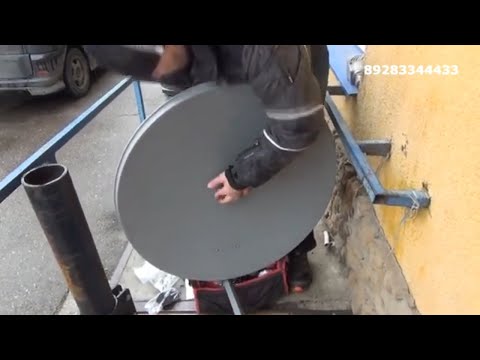
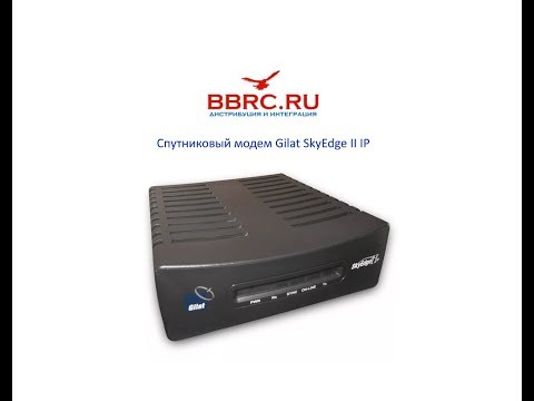
Gilat SkyEdge II IP Спутниковый модем обзорПодробнее
Инструкция по установке и наведению на спутник терминалов Gilat GeminiПодробнее
Пособие по VSAT — Установка спутниковой антенны 75см и модема MDM2200 системы — Sat3PlayПодробнее
Пособие по VSAT — Установка спутниковой антенны 1м и модема MDM2200 системы — Sat3PlayПодробнее
Инструкция по установке спутникового интернета Газпром на спутник Ямал 601Подробнее

Монтаж и наведение VSAT iDirect Evolution в сеть СатисСвязьПодробнее
Gilat Двухсторонний спутниковый интернетПодробнее
Спутниковый недорогой интернет в автомобиль? Да! Настройка оборудования Scorpio GilatПодробнее
ТАК СМОЖЕТ ЛЮБОЙ/КАК НАСТРОИТЬ СПУТНИКОВЫЙ ИНТЕРНЕТ/Подробнее

Настройка антенны спутникового интернета ALTEGROSKY, АСТРА ИНТЕРНЕТ своими руками (HUGHES JUPITER)Подробнее
Спутниковый интернет в деревню, своими руками!Подробнее
Gilat SkyEdge II-c-The New Flexible in Internet ConnectivityПодробнее

Спутниковый интернет на дачу скорость 100 мегабитПодробнее
Спутниковый интернет в Луганской и Донецкой областиПодробнее