Instruction:

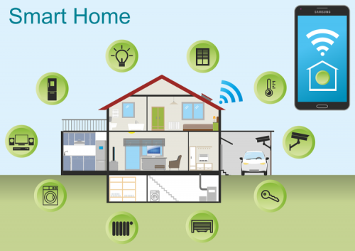
This Smart Home Learning Kit based on the Arduino platform is newly rolled out by Keyestudio DIY Robot Co. Ltd.
It simulates the real smart home and demonstrates the cozy and comfortable life for people.
This system adopts PLUS main control board and multiple modules, including 1602 LCD, photocell sensor, analog gas(MQ-2) sensor, PIR motion sensor, yellow LED, servo, steam sensor and Bluetooth.
In fact, Bluetooth controls everything in smart home: light intensity, humidity, flammable gas concentration, doors openning and closing. Everything is controlled via APPs on smart phones/IPad and will be displayed on 1602 LCD in real time.
We totally provide 3 programming languages: C language, Mixly and Scratch. These languages hit the top list in programming, which is easy and convenient to use and understand.
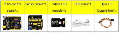
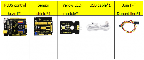
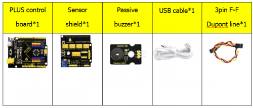
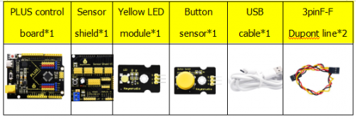
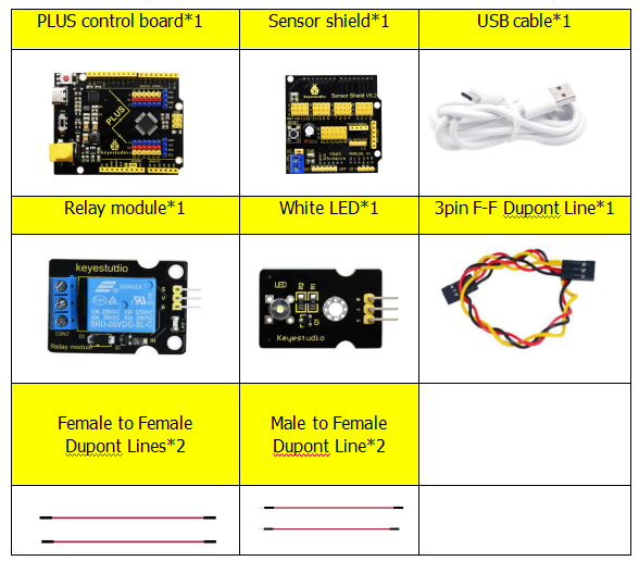
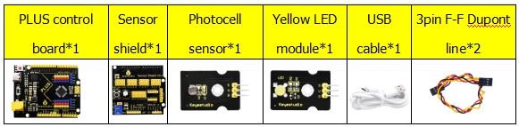
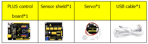
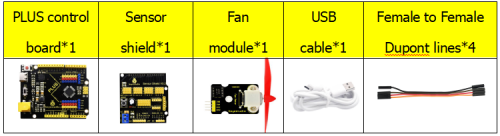
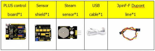
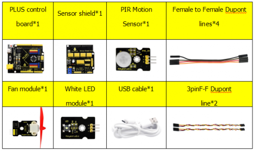
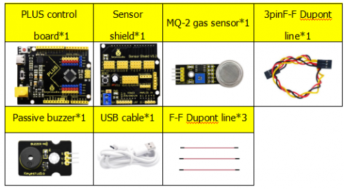
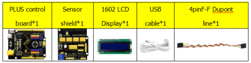
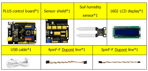
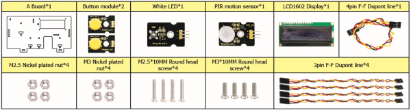
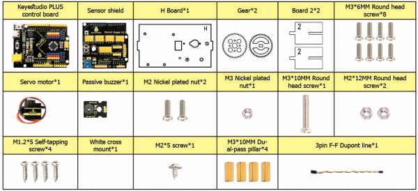
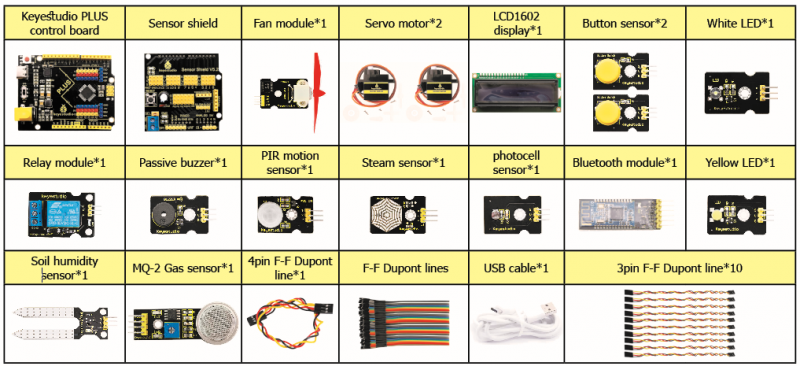
Kit List
Download software and install driver
Download software
When we get control board, we need to download Arduino IDE and driver firstly.
You could download Arduino IDE from the official website:
https://www.arduino.cc/, click the SOFTWARE on the browse bar, click “DOWNLOADS” to enter download page, as shown below:
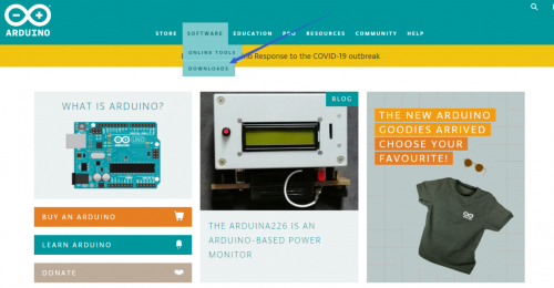
There are various versions for Arduino, just download a suitable version for your system, we will take WINDOWS system as an example to show you how to download and install.
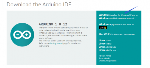
There are two versions for WINDOWS system, one is installed version, another one is download version, you just need to download file to computer directly and unzip it. These two versions can be used normally. Choose one and download on your computer.

You just need to click JUST DOWNLOAD, then click the downloaded file to install it. And when the ZIP file is downloaded, you can directly unzip and start it.
Keyestudio PLUS Control Board
Description
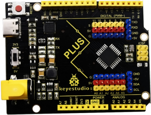
Keyestudio PLUS control board is fully compatible with Arduino IDE development environment. It contains all the functions of the Arduino UNO board. Moreover, some improvements we made highly strengthen its function. It is the best choice to learn how to build circuit and write code as well. Let’s get started!
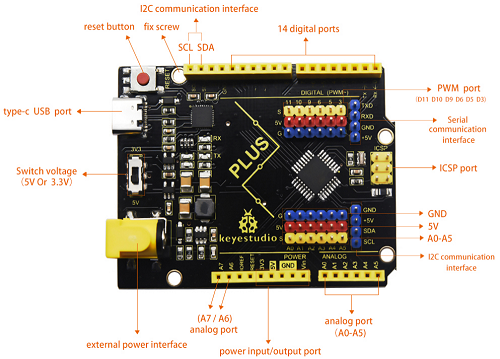
- Serial communication interface: D0 is RX, D1 is TX
- PWM interface (pulse width modulation): D3 D5 D6 D9 D10 D11
- External interrupt interface: D2 (interrupt 0) and D3 (interrupt 1)
- SPI communication interface: D10 is SS, D11 is MOSI, D12 is MISO, D13 is SCK
- IIC communication port: A4 is SDA, A5 is SCL
Installing driver
Let’s install the driver of keyestudio PLUS control board. The USB-TTL chip on PLUS board adopts CP2102 serial chip. The driver program of this chip is included in Arduino 1.8 version and above, which is convenient. Plug on USB port of board, the computer can recognize the hardware and automatically install the driver of CP2102.
If install unsuccessfully, or you intend to install manually, open the device manager of computer. Right click Computer—— Properties—— Device Manager.
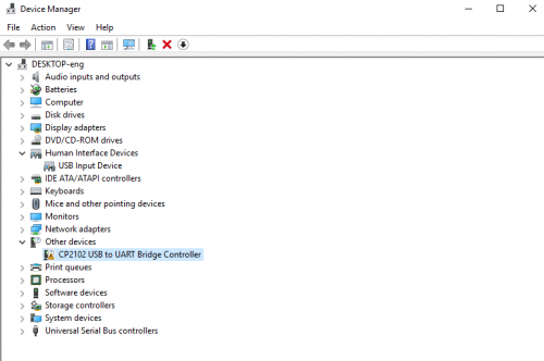
There is a yellow exclamation mark on the page, which implies installing the driver of CP2102 unsuccessfully. Then we double click the hardware and update the driver.
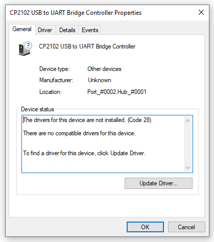
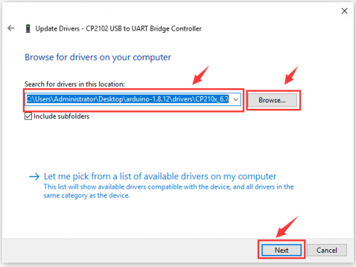
Click “OK” to enter the following page, click “browse my computer for updated driver software”, find out the installed or downloaded ARDUINO software. As shown below:
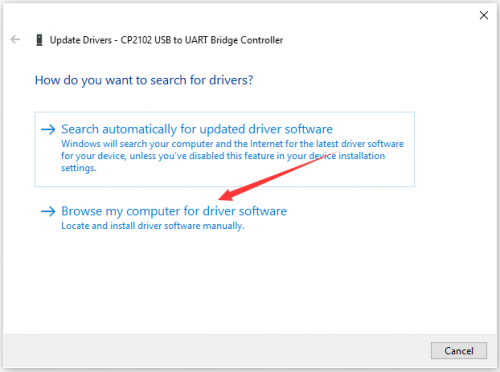
There is a DRIVERS folder in Arduino software installed package(![]() ), open driver folder and you can see the driver of CP210X series chips.
), open driver folder and you can see the driver of CP210X series chips.
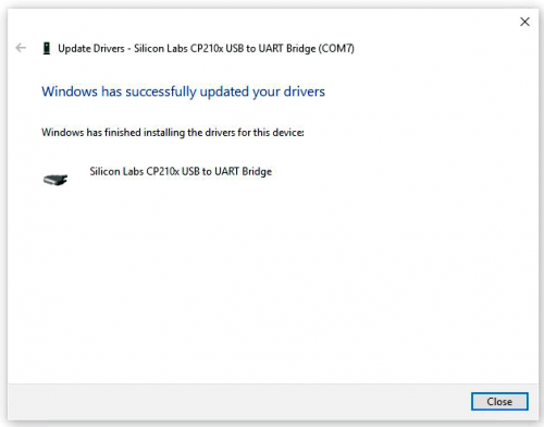
We click “Browse”, then find out the driver folder, or you could enter “driver” to search in rectangular box, then click “next”, the driver will be installed successfully. (I place Arduino software folder on the desktop, you could follow my way)
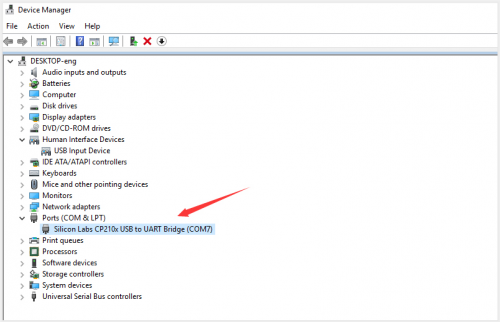
Open device manager, we will find the yellow exclamation mark disappear. The driver of CP2102 is installed successfully.
Arduino IDE Setting
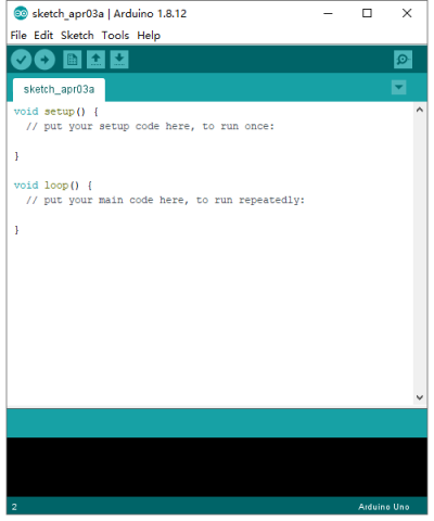
Click icon,open Arduino IDE.
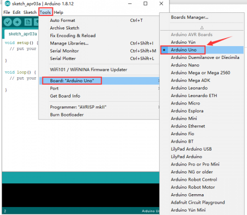
To avoid the errors when uploading the program to the board, you need to select the correct Arduino board that matches the board connected to your computer.
Then come back to the Arduino software, you should click Tools→Board, select the board. (as shown below)
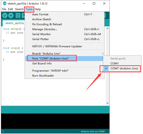
Then select the correct COM port (you can see the corresponding COM port after the driver is successfully installed)
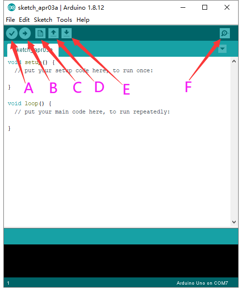
Before uploading the program to the board, let’s demonstrate the function of each symbol in the Arduino IDE toolbar.
A- Used to verify whether there is any compiling mistakes or not.
B- Used to upload the sketch to your Arduino board.
C- Used to create shortcut window of a new sketch.
D- Used to directly open an example sketch.
E- Used to save the sketch.
F- Used to send the serial data received from board to the serial monitor.
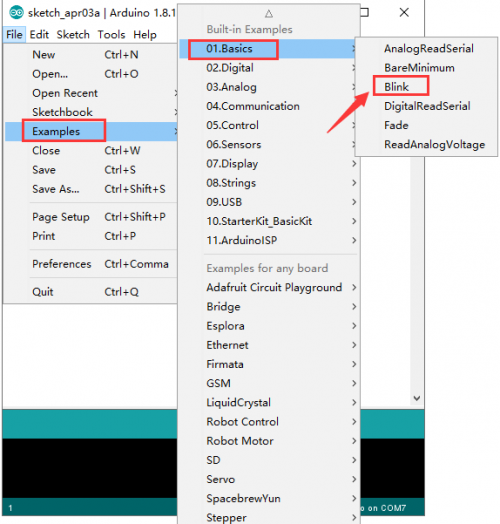
Start your first program
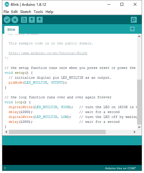
Open the file to select Example, choose BLINK from BASIC, as shown below:
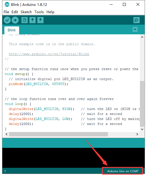
Set board and COM port, the corresponding board and COM port are shown on the lower right of IDE.
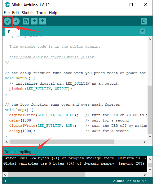
Click ![]() to start compiling the program, check errors.
to start compiling the program, check errors.
Click ![]() to upload the program, upload successfully.
to upload the program, upload successfully.
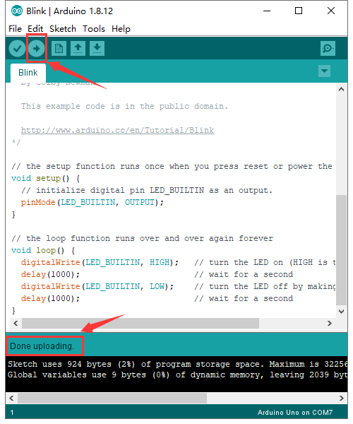
Upload the program successfully, the onboard LED lights on for 1s, lights off for 1s. Congratulation, you finish the first program.
How to Add a Library?
What are Libraries ?
Libraries are a collection of code that makes it easy for you to connect to a sensor,display, module, etc.
For example, the built-in LiquidCrystal library helps talk to LCD displays. There are hundreds of additional libraries available on the Internet for download.
The built-in libraries and some of these additional libraries are listed in the reference.
Here we will introduce the most simple way for you to add libraries.
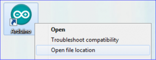
Step 1:After downloading well the Arduino IDE, you can right-click the icon of Arduino IDE.
Find the option «Open file location» shown as below:
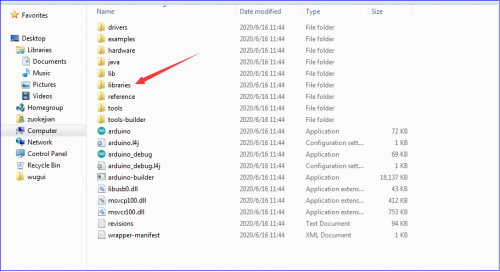
Step 2: Enter it to find out libraries folder which is the library file of Arduino.
Step 3:Next to find out the“libraries”of smart home(seen in the link: https://fs.keyestudio.com/KS0085), as shown below:
You just need to replicate and paste 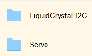 into the libraries folder of Arduino IDE.
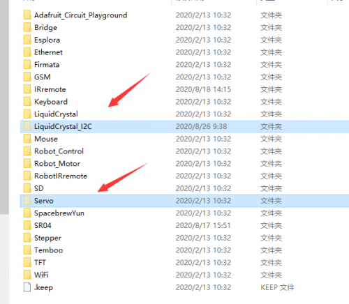
The library of home smart is successfully installed, as shown below:
Projects

Alright, let’s get straight to our projects. In this kit, there are 14 sensors and modules included. We will start with the simple sensor to make you know the smart home deeply.
However, if you are an enthusiast with Arduino knowledge. You could skip theses steps, assemble the smart home kit directly(there is assembly video in the folder)
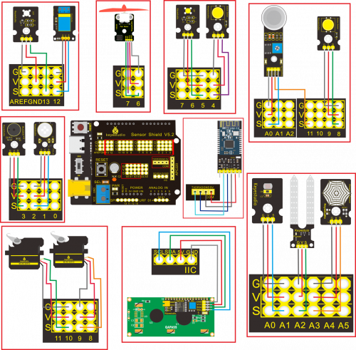
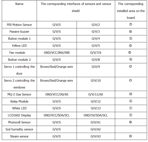
Note: In this course, the interface of each sensor / module marked with (G,-, GND) indicates the negative pole, G is connected to G or — or GND of sensor shield or control board; “V” implies positive pole which is linked with V or VCC or 5V.
Project 1: LED Blink
Description:
In previous lesson, we installed the driver of keystudio V4.0 development board, we start from simple projects. For this lesson we will perform “Arduion blinks LED”, which is the basic practice for starter.
We provide a test code to control LED to perform blinking effect. In the code, you could set distinct flashing scene by changing the time of lighting on and off. Power on GND and VCC, the LED will light on when signal end S is high level, on the contrary, LED will turn off when signal end S is low level.
Specifications:
- Control interface: digital port
- Working voltage: DC 3.3-5V
- Pin pitch: 2.54mm
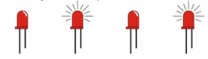
- LED display color: white
- Size: 30 * 20mm
- Weight: 3g
Equipment:
Sensor shield
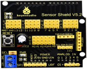
We usually combine Arduino control board with other sensors, modules and multiple sensors, which is difficult to wire. Conversely, this sensor shield cover this problem, you just need to stack on keyestudio PLUS control board when you use it.
This shield can be directly inserted into 3PIN sensors, it breaks out the common used communication ports as well, such as serial communication, IIC communication, SPI communication. What’s more, the shield comes with a reset button and 2 signal lights.
Pins Description

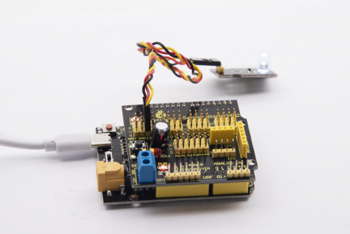
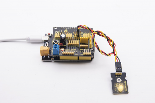
Connection Diagram:
Next to wire, link LED module with D13 of shield.
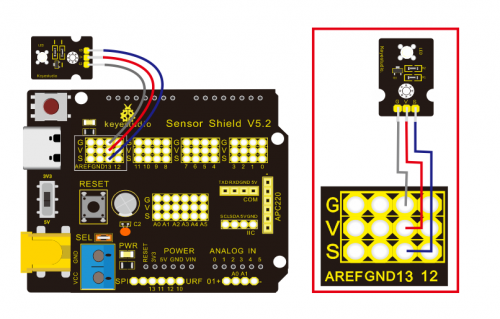
Note: G, V and S of white LED module are linked with G, V and 13 of expansion board.
Test Code:
/*
Keyestudio smart home Kit for Arduino
Project 1
Blink
http://www.keyestudio.com
*/
void setup() {
  // initialize digital pin 13 as an output.
  pinMode(13, OUTPUT);
}
// the loop function runs over and over again forever
void loop() {
  digitalWrite(13, HIGH);   // turn the LED on (HIGH is the voltage level)
  delay(1000);              // wait for a second
  digitalWrite(13, LOW);    // turn the LED off by making the voltage LOW
  delay(1000);              // wait for a second
}//
Test Result:
Upload test code successfully, white LED starts blinking, lights on for 1000ms, lights off for 1000ms, alternately.
Code Explanation
The code looks long and clutter, but most of which are comment. The grammar of Arduino is based on C.
Comments generally have two forms of expression:
/* …….*/ : suitable for long paragraph comments
// : suitable for mono line comments
So the code contains the many vital information, such as the author, the issued agreement, etc.
Most people omit comments, starter should develop a good habit of looking through code. Firstly, check comments. They contain the provided information and do help you understand test code quickly. Secondly, form the habit of writing comments
// the setup function runs once when you press reset or power the board
void setup() {
  // initialize digital pin 13 as an output.
  pinMode(13, OUTPUT);
}
According to comments, we will find that author define the D13 pin mode as digital output in setup() function. Setup() is the basic function of Arduino. It will execute once in the running of program, usually as definition pin, define and ensure the variables.
// the loop function runs over and over again forever
void loop() {
  digitalWrite(13, HIGH);   // turn the LED on (HIGH is the voltage level)
  delay(1000);              // wait for a second
  digitalWrite(13, LOW);    // turn the LED off by making the voltage LOW
  delay(1000);              // wait for a second
}
Loop() is the necessary function of Arduino, it can run and loop all the time after “setup()” executes once
In the loop()function, author uses
digitalWrite(13, HIGH); // turn the LED on (HIGH is the voltage level)
digitalWrite(): set the output voltage of pin to high or low level. We make D13 output high level, then the LED lights on.
delay(1000); // wait for a second
Delay function is used for delaying time, 1000ms is 1s, unit is ms
digitalWrite(13, LOW); // turn the LED off by making the voltage LOW
Similarly, we make D13 output low level, LED will turn off.
delay(1000); // wait for a second
Delay for 1s, light on LED—keep on 1s—light off LED—stay on 1s, iterate the process. LED flashes with 1-second interval. What if you want to make LED flash rapidly? You only need to modify the value of delay block. Reducing the delay value implies that the time you wait is shorter, that is, flashing rapidly. Conversely, you could make LED flash slowly.
Project 2: Breathing Light

Description
In the previous lesson, we control LED on and off and make it blink.
In this project, we will control LED brightness through PWM to simulate breathing effect. Similarly, you can change the step length and delay time in the code so as to demonstrate different breathing effect.
PWM is a means of controlling the analog output via digital means. Digital control is used to generate square waves with different duty cycles (a signal that constantly switches between high and low levels) to control the analog output.In general, the input voltage of port are 0V and 5V. What if the 3V is required? Or what if switch among 1V, 3V and 3.5V? We can’t change resistor constantly. For this situation, we need to control by PWM.
For the Arduino digital port voltage output, there are only LOW and HIGH, which correspond to the voltage output of 0V and 5V. You can define LOW as 0 and HIGH as 1, and let the Arduino output five hundred 0 or 1 signals within 1 second.
If output five hundred 1, that is 5V; if all of which is 1, that is 0V. If output 010101010101 in this way then the output port is 2.5V, which is like showing movie. The movie we watch are not completely continuous. It actually outputs 25 pictures per second. In this case, the human can’t tell it, neither does PWM. If want different voltage, need to control the ratio of 0 and 1. The more 0,1 signals output per unit time, the more accurately control.
Equipment:
Connection Diagram:
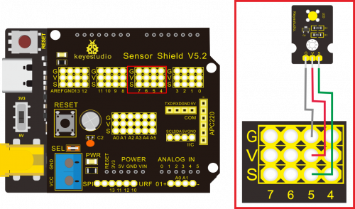
Note: on sensor shield, the G, V and S pins of yellow LED module are linked with G, V and 5.
Test Code:
 /*
Keyestudio smart home Kit for Arduino
Project 2
PWM
http://www.keyestudio.com
*/
int ledPin = 5; // Define the LED pin at D5
void setup () {
      pinMode (ledPin, OUTPUT); // initialize ledpin as an output.
}
void loop () {
for (int value = 0; value<255; value = value + 1) {
     analogWrite (ledPin, value); // LED lights gradually light up
     delay (5); // delay 5MS
   }
   for (int value = 255; value>0; value = value-1) {
     analogWrite (ledPin, value); // LED gradually goes out
     delay (5); // delay 5MS
   }}
//
Test Result:
Upload test code successfully, LED gradually becomes brighter then darker, like human breath, rather than light on and off immediately
Code analysis
When we need to repeat some statements, we have to use “for” statement
For statement format as follows:
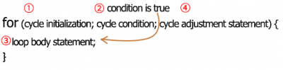
“for” cyclic sequence:
Round 1:1 → 2 → 3 → 4
Round 2:2 → 3 → 4
…
Until number 2 is not established, “for”loop is over,
After knowing this order, go back to code:
for (int value = 0; value < 255; value=value+1){
        ...
}
for (int value = 255; value >0; value=value-1){
       ...
}
The two “for”statement make value increase from 0 to 255, then reduce from 255 to 0, then increase to 255,….infinite loop
There is a new function in “for” statement —— analogWrite()
We know that digital port only has two state of 0 and 1. So how to send an analog value to a digital value? Here, we need this function, observe the Arduino board and you will find 6 pins with “~”. They are different from other pins and can output PWM signals.
Function format as follows:
analogWrite(pin,value)
analogWrite() is used to write an analog value from 0~255 for PWM port, so the value is in the range of 0~255, attention that you only write the digital pins with PWM function, such as pin 3, 5, 6, 9, 10, 11.
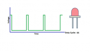
PWM is a technology to obtain analog quantity through digital method. Digital control forms a square wave, and the square wave signal only has two states of switching (that is, high or low levels of our digital pins). By controlling the ratio of the duration of on and off, a voltage varying from 0 to 5V can be simulated. The time taken(academically referred to as high level) is called pulse width, so PWM is also called pulse width modulation.
Through the following five square waves, let’s know more about PWM.
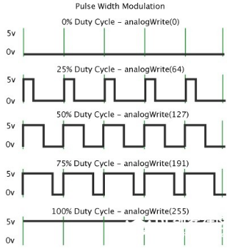
In the above figure, the green line represents a period, and value of analogWrite() corresponds to a percentage which is called Duty Cycle as well. Duty cycle implies that high-level duration is divided by low-level duration in a cycle. From top to bottom, the duty cycle of first square wave is 0% and its corresponding value is 0. The LED brightness is lowest, that is, turn off. The more time high level lasts, the brighter the LED. Therefore, the last duty cycle is 100%, which correspond to 255, LED is brightest. 25% means darker.
PWM mostly is used for adjusting the LED brightness or rotation speed of motor.
Project 3: Passive Buzzer
Description
There are prolific interactive works completed by Arduino. The most common one is sound and light display. We always use LED to make experiments. For this lesson, we design circuit to emit sound. The universal sound components are buzzer and horns. Buzzer is easier to use. And buzzer includes about active buzzer and passive buzzer. In this experiment, we adopt passive buzzer.
While using passive buzzer, we can control different sound by inputting square waves with distinct frequency. During the experiment, we control code to make buzzer sound, begin with “tick, tick” sound, then make passive buzzer emit “do re mi fa so la si do”, and play specific songs.
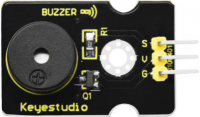
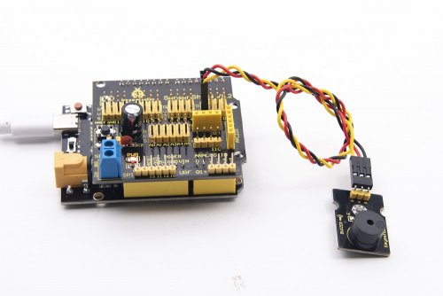
Equipment
Connection Diagram:
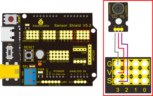
Note: The G, V, and S port of the passive buzzer module are separately connected to G, V, and 3 on the shield, power up.
Test Code:
 /*
Keyestudio smart home Kit for Arduino
Project 3.1
Buzzer
http://www.keyestudio.com
*/
int tonepin = 3; // Set the Pin of the buzzer to the digital D3
     void setup ()
     {
       pinMode (tonepin, OUTPUT); // Set the digital IO pin mode to output
     }
     void loop ()
     {
       unsigned char i, j;
       while (1)
       {
         for (i = 0; i <80; i ++) // output a frequency sound
         {
           digitalWrite (tonepin, HIGH); // Sound
           delay (1); // Delay 1ms
           digitalWrite (tonepin, LOW); // No sound
           delay (1); // Delay 1ms
         }
         for (i = 0; i <100; i ++) // output sound of another frequency
         {
           digitalWrite (tonepin, HIGH); // Sound
           delay (2); // delay 2ms
           digitalWrite (tonepin, LOW); // No sound
           delay (2); // delay 2ms
         }}}
//
Test Result:
From the above code, 80 and 100 decide frequency in “for” statement. Delay controls duration, like the beat in music.
We will play fabulous music if we control frequency and beats well, so let’s figure out the frequency of tones. As shown below:
After knowing the frequency of tone, next to control the time the note plays. The music will be produces when every note plays a certain amount of time. The note rhythm is divided into one beat, half beat, 1/4 beat, 1/8 beat, we stipulate the time for a note to be 1, half beat is 0.5, 1/4 beat is 0.25, 1/8 beat is 0.125….., Therefore, the music is played.
We will take example of “Ode to joy”

From notation, the music is 4/4 beat.
There are special notes we need to explain:
1.Normal note, like the first note 3, correspond to 350(frequency), occupy 1 beat
2.The note with underline means 0.5 beat
3.The note with dot(3.)means that 0.5 beat is added, that is 1+0.5 beat
4.The note with”—” represents that 1 beat is added, that is 1+1 beat.
5.The two successive notes with arc imply legato, you could slightly modify the frequency of the note behind legato(need to debug it yourself), such like reducing or increasing some values, the sound will be more smoother.
/*
Keyestudio smart home Kit for Arduino
Project 3.2
Buzzer music
http://www.keyestudio.com
*/
#define NTD0 -1
#define NTD1 294
#define NTD2 330
#define NTD3 350
#define NTD4 393
#define NTD5 441
#define NTD6 495
#define NTD7 556

#define NTDL1 147
#define NTDL2 165
#define NTDL3 175
#define NTDL4 196
#define NTDL5 221
#define NTDL6 248
#define NTDL7 278

#define NTDH1 589
#define NTDH2 661
#define NTDH3 700
#define NTDH4 786
#define NTDH5 882
#define NTDH6 990
#define NTDH7 112
// List all D-tuned frequencies
#define WHOLE 1
#define HALF 0.5
#define QUARTER 0.25
#define EIGHTH 0.25
#define SIXTEENTH 0.625
// List all beats
int tune [] = // List each frequency according to the notation
{
  NTD3, NTD3, NTD4, NTD5,
  NTD5, NTD4, NTD3, NTD2,
  NTD1, NTD1, NTD2, NTD3,
  NTD3, NTD2, NTD2,
  NTD3, NTD3, NTD4, NTD5,
  NTD5, NTD4, NTD3, NTD2,
  NTD1, NTD1, NTD2, NTD3,
  NTD2, NTD1, NTD1,
  NTD2, NTD2, NTD3, NTD1,
  NTD2, NTD3, NTD4, NTD3, NTD1,
  NTD2, NTD3, NTD4, NTD3, NTD2,
  NTD1, NTD2, NTDL5, NTD0,
  NTD3, NTD3, NTD4, NTD5,
  NTD5, NTD4, NTD3, NTD4, NTD2,
  NTD1, NTD1, NTD2, NTD3,
  NTD2, NTD1, NTD1
};
float durt [] = // List the beats according to the notation
{
  1,1,1,1,
  1,1,1,1,
  1,1,1,1,
  1 + 0.5,0.5,1 + 1,
  1,1,1,1,
  1,1,1,1,
  1,1,1,1,
  1 + 0.5,0.5,1 + 1,
  1,1,1,1,
  1,0.5,0.5,1,1,
  1,0.5,0.5,1,1,
  1,1,1,1,
  1,1,1,1,
  1,1,1,0.5,0.5,
  1,1,1,1,
  1 + 0.5,0.5,1 + 1,
};
int length;
int tonepin = 3; // Use interface 3
void setup ()
{
  pinMode (tonepin, OUTPUT);
  length = sizeof (tune) / sizeof (tune [0]); // Calculate length
}
void loop ()
{
  for (int x = 0; x <length; x ++)
  {
    tone (tonepin, tune [x]);
    delay (350* durt [x]); // This is used to adjust the delay according to the beat, 350 can be adjusted by yourself.
    noTone (tonepin);
  }
  delay (2000); // delay 2S
}
//
Upload test code on the development board, do you hear “Ode to joy”?
Project 4:Controlling LED by Button Module
Description:
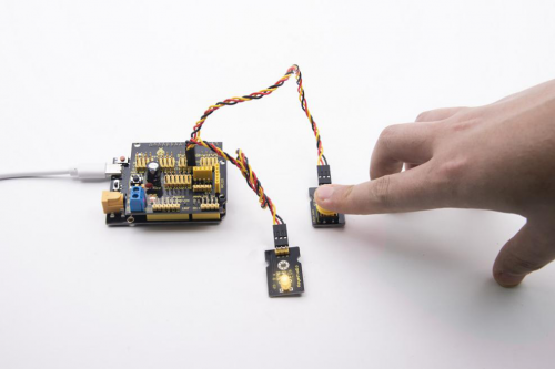
In this project, we will control LED to light on and off via button module. When the button is pressed, the signal end outputs low level (0); when released, the signal end of sensor keeps high level(1).
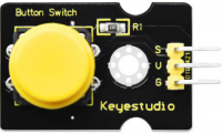
Equipment
Connection Diagram:
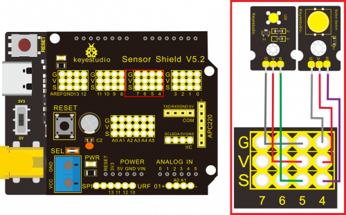
Note: The G, V, and S pins of button sensor module are separately connected to G, V, and 4 on the shield, and the G, V, and S pins of the yellow LED module are connected to G, V, and 5 on the shield.
Test Code:
Next to design the program, we make LED on by button. Comparing with previous experiments, we add a conditional judgement statement. We use if statement. The written sentences of Arduino is based on C language, therefore, the condition judgement statement of C is suitable for Arduino, like while, swich, etc.
For this lesson, we take simple “if” statement as example to demonstrate:
If button is pressed, digital 4 is low level, then we make digital 5 output high level , then LED will be on; conversely, if the button is released, digital 4 is high level, we make digital 5 output low level, then LED will go off.
As for your reference:
/ *
Keyestudio smart home Kit for Arduino
Project 4
Button
http://www.keyestudio.com
* /
int ledpin = 5; // Define the led light in D5
int inpin = 4; // Define the button in D4
int val; // Define variable val
void setup ()
{
pinMode (ledpin, OUTPUT); // The LED light interface is defined as output
pinMode (inpin, INPUT); // Define the button interface as input
}
void loop ()
{
val = digitalRead (inpin); // Read the digital 4 level value and assign it to val
if (val == LOW) // Whether the key is pressed, the light will be on when pressed
{digitalWrite (ledpin, HIGH);}
else
{digitalWrite (ledpin, LOW);}
}
//
Test Result:
This experiment is pretty simple, and widely applied to various of circuits and electrical appliances. In our life, you could find this principle on any device, such as the backlight is on when press any buttons, which is the typical appliance.
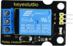
Project 5:1-channel Relay Module
Description
This module is an Arduino dedicated module, and compatible with arduino sensor expansion board. It has a control system (also called an input loop) and a controlled system (also called an output loop).
Commonly used in automatic control circuits, the relay module is an «automatic switch» that controls a larger current and a lower voltage with a smaller current and a lower voltage.
Therefore, it plays the role of automatic adjustment, safety protection and conversion circuit in the circuit. It allows Arduino to drive loads below 3A, such as LED light strips, DC motors, miniature water pumps, solenoid valve pluggable interface.
The main internal components of the relay module are electromagnet A, armature B, spring C, moving contact D, static contact (normally open contact) E, and static contact (normally closed contact) F, (as shown in the figure ).
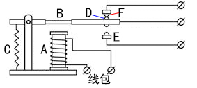
As long as a certain voltage is applied to both ends of the coil, a certain current will flow through the coil to generate electromagnetic effects, and the armature will attract the iron core against the pulling force of the return spring under the action of electromagnetic force attraction, thereby driving the moving contact and the static contact (normally open contact) to attract. When the coil is disconnected, the electromagnetic suction will also disappear, and the armature will return to the original position under the reaction force of the spring, releasing the moving contact and the original static contact (normally closed contact). This pulls in and releases, thus achieving the purpose of turning on and off in the circuit. The «normally open and closed» contacts of the relay can be distinguished in this way: the static contacts on disconnected state when the relay coil is powered off are called «normally open contacts»; the static contacts on connected state are called «normally closed contact». The module comes with 2 positioning holes for you to fix the module to other equipment.
Specifications:
- Working voltage: 5V (DC)
- Interface: G, V, S interface
- Input signal: digital signal (high level 1, low level 0)
- Contacts: static contacts (normally open contacts, normally closed contacts) and moving contacts
- Rated current: 10A (NO) 5A (NC)
- Maximum switching voltage: 150 V (AC) 24 V (DC)
- Electric shock current: less than 3A
- Weight: 15g
- Contact action time: 10ms
Equipment:
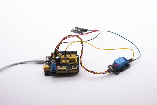
Connection Diagram:
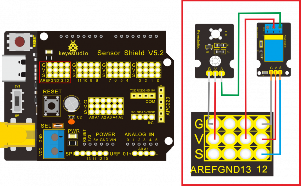
Note: On the shield, the G, V, and S pins of 1-channel relay module are connected to G, V, and 12 respectively. The NO is linked with V; the G, V, and S pins of white LED are respectively connected to G, V, and the static contact of NO on relay module.
Test Code:
/*
Keyestudio smart home Kit for Arduino
Project 5
Relay
http://www.keyestudio.com
*/
int Relay = 12; // Define the relay pin at D12
void setup ()
{
pinMode (13, OUTPUT); // Set Pin13 as output
digitalWrite (13, HIGH); // Set Pin13 High
pinMode (Relay, OUTPUT); // Set Pin12 as output
}
void loop ()
{
digitalWrite (Relay, HIGH); // Turn off relay
delay (2000);
digitalWrite (Relay, LOW); // Turn on relay
delay (2000);
}
//
Test Result:
Wire, power up and upload test code. The relay is connected(“NO” is on , NC is off) for 0.5s, then disconnected for 0.5s (NC is on, NO is off), and alternately. When the relay is connected, the white LED will be on, conversely, the white LED will go off.
Project 6:Photocell Sensor
Description

The photocell sensor (photoresistor) is a resistor made by the photoelectric effect of a semiconductor. It is very sensitive to ambient light, thus its resistance value vary with different light intensity.
We use its features to design a circuit and generate a photoresistor sensor module. The signal end of the module is connected to the analog port of the microcontroller. When the light intensity increases, the resistance decreases, and the voltage of the analog port rises, that is, the analog value of the microcontroller also goes up. Otherwise, when the light intensity decreases, the resistance increases, and the voltage of the analog port declines. That is, the analog value of the microcontroller becomes smaller. Therefore, we can use the photoresistor sensor module to read the corresponding analog value and sense the light intensity in the environment.
It is commonly applied to light measurement, control and conversion, light control circuit as well.
Specifications:
- Working voltage: 3.3V-5V (DC)
- Interface: 3PIN interface
- Output signal: analog signal
- Weight: 2.3g
Equipment:
Connection Diagram:
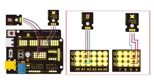
Note: On the expansion board, the G, V, and S pins of the photocell sensor module are connected to G, V, and A1; the G, V, and S pins of the yellow LED module are linked with G, V, and 5 separately.
Test Code:
/*
Keyestudio smart home Kit for Arduino
Project 6
photocell
http://www.keyestudio.com
*/
int LED = 5; // Set LED pin at D5
int val = 0; // Read the voltage value of the photodiode
void setup () {
       pinMode (LED, OUTPUT); // LED is output
       Serial.begin (9600); // The serial port baud rate is set to 9600
}
void loop () {
       val = analogRead (A1); // Read the voltage value of A1 Pin
       Serial.println (val); // Serial port to view the change of voltage value
       if (val <900)
       {// Less than 900, LED light is off
       digitalWrite (LED, LOW);
       }
       else
       {// Otherwise, the LED lights up
       digitalWrite (LED, HIGH);
       }
       delay (10); // Delay 10ms
}
//
Test Result:
LED will be on after uploading test code, point at the photocell sensor with flashlight (or the flash from cellphone), you’ll find that LED is automatically off. However, take away the flashlight, LED will be on again.
Review
For this code string, it is simply. We read value through analog port, please attention that analog quantity doesn’t need input and output mode.Read the analog value of photocell sensor by analog port.
The analog value will gradually decreases once there is light, the value is up to 1000, this value can be chosen according to brightness you need. Select method: put the whole device in the environment where LED is off, open serial monitor to check shown value, replace 1000 with this value. Read value from serial monitor is a good way to modulate code
Project 7:Adjusting Motor Servo Angle
Description
When we make this kit, we often control doors and windows with servos. In this course, we’ll introduce its principle and how to use servo motors.
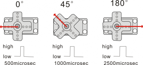
Servo motor is a position control rotary actuator. It mainly consists of housing, circuit board, core-less motor, gear and position sensor. Its working principle is that the servo receives the signal sent by MCU or receiver and produces a reference signal with a period of 20ms and width of 1.5ms, then compares the acquired DC bias voltage to the voltage of the potentiometer and outputs a voltage difference.
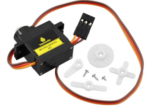
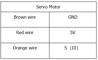
Servo motor comes with many specifications. But all of them have three connection wires, distinguished by brown, red, orange colors (different brand may have different color).
Brown one is for GND, red one for power positive, orange one for signal line.
The rotation angle of servo motor is controlled by regulating the duty cycle of PWM (Pulse-Width Modulation) signal. The standard cycle of PWM signal is 20ms (50Hz). Theoretically, the width is distributed between 1ms-2ms, but in fact, it’s between 0.5ms-2.5ms. The width corresponds the rotation angle from 0° to 180°. But note that for different brand motor, the same signal may have different rotation angle.
There are two ways to control a servomotor with Arduino.
One is to use a common digital sensor port of Arduino to produce square wave with different duty cycle to simulate PWM signal and use that signal to control the positioning of the motor.
Another way is to directly use the Servo function of the Arduino to control the motor. In this way, the program will be easier but it can only control two-contact motor because for the servo function, only digital pin 9 and 10 can be used.
The Arduino drive capacity is limited. So if you need to control more than one motor, you will need external power.
Specifications:
Working voltage: DC 4.8V ~ 6V
Operating angle range: about 180 ° (at 500 → 2500 μsec)
Pulse width range: 500 → 2500 μsec
No-load speed: 0.12 ± 0.01 sec / 60 (DC 4.8V) 0.1 ± 0.01 sec / 60 (DC 6V)
No-load current: 200 ± 20mA (DC 4.8V) 220 ± 20mA (DC 6V)
Stopping torque: 1.3 ± 0.01kg · cm (DC 4.8V) 1.5 ± 0.1kg · cm (DC 6V)
Stop current: ≦ 850mA (DC 4.8V) ≦ 1000mA (DC 6V)
Standby current: 3 ± 1mA (DC 4.8V) 4 ± 1mA (DC 6V)
Lead length: 250 ± 5 mm
Appearance size: 22.9 * 12.2 * 30mm
Weight: 9 ± 1 g (without servo horn)
Storage temperature: -20 ℃ ~ 60 ℃
Operating temperature: -10 ℃ ~ 50 ℃
Experiment equipment:
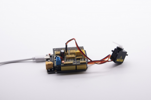
Connection Diagram:
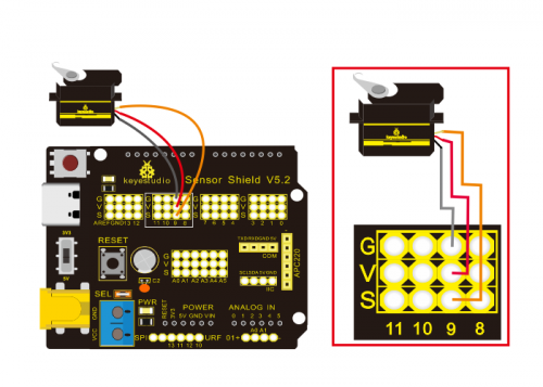
Note: The servo is connected to G (GND), V (VCC), 9. The brown wire of the servo is connected to Gnd (G), the red wire is linked with 5v (V), and the orange wire is connected to digital pin 9.
Test Code:
/*
Keyestudio smart home Kit for Arduino
Project 7
Sevro
http://www.keyestudio.com
*/
#include <Servo.h> // Servo function library
Servo myservo;
int pos = 0; // Start angle of servo
void setup ()
{
myservo.attach (9); // Define the position of the servo on D9
}
void loop ()
{
for(pos = 0; pos < 180; pos += 1)// angle from 0 to 180 degrees
{
myservo.write (pos); // The servo angle is pos
delay (15); // Delay 15ms
}
for(pos = 180; pos>=1; pos-=1) // Angle from 180 to 0 degrees
{
myservo.write (pos); // The angle of the servo is pos
delay (15); // Delay 15ms
}
}
//
Test Result:
Upload code, wire according to connection diagram, and power on. The servo rotates from 0° to 180° then from 180°~0°
Project 8:Fan Module
Description
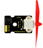
The L9110 fan module adopts L9110 motor control chip, it can control the rotation direction and speed of the motor. Moreover, this module is efficient and with high quality fan, which can put out the flame within 20cm distance. Similarly, it is an important part of fire robot as well.
Specifications:
- Fan diameter: 75mm
- Working voltage: 5V
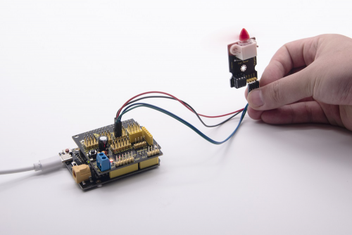
Equipment:
Connection Diagram:
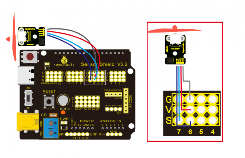
Note: On the shield, the GND, VCC, INA, and INB pins of the fan module are respectively connected to G, V, 7, 6.
Test Code:
/*
Keyestudio smart home Kit for Arduino
Project 8
Fan
http://www.keyestudio.com
*/
void setup () {
   pinMode (7, OUTPUT); //define D7 pin as output
   pinMode (6, OUTPUT); //define  D6 pin as output
}
void loop () {
   digitalWrite (7, LOW);
   digitalWrite (6, HIGH); // Reverse rotation of the motor
   delay (3000); // delay 3S
   digitalWrite (7, LOW);
   digitalWrite (6, LOW); // The motor stops rotating
   delay (1000); //delay 1S
   digitalWrite (7, HIGH);
   digitalWrite (6, LOW); // The motor rotates in the forward direction
   delay (3000); // delay 3S
}
//
Test Result:
Upload test code, wire according to connection diagram, the DIP switch is dialed to right side and power on. The fan rotates counterclockwise for 3000ms, stops for 1000ms, then rotates clockwise for 3000ms.
Project 9:Steam Sensor
Description
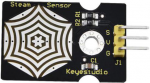
This is a commonly used steam sensor. Its principle is to detect the amount of water by bare printed parallel lines on the circuit board. The more the water is, the more wires will be connected. As the conductive contact area increases, the output voltage will gradually rise. It can detect water vapor in the air as well. The steam sensor can be used as a rain water detector and level switch. When the humidity on the sensor surface surges, the output voltage will increase.
The sensor is compatible with various microcontroller control boards, such as Arduino series microcontrollers. When using it, we provide the guide to operate steam sensor and Arduino control board. Connect the signal end of the sensor to the analog port of the microcontroller, sense the change of the analog value, and display the corresponding analog value on the serial monitor.
Note: the connect part is not waterproof, don’t immerse it in the water please.
Specifications:
- Working voltage: DC 3.3-5V
- Working current: <20mA
- Operating temperature range: -10 ℃ ~ + 70 ℃;
- Control signal: analog signal output
- Interface: 2.54mm 3pin pin interface
- Size: 35 * 20 * 8mm
- Weight: 2.2g
- S: signal output
- V (+): Power supply (VCC)
- G (-): Ground (GND)
Equipment:
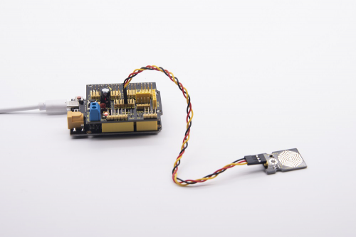
Connection Diagram:
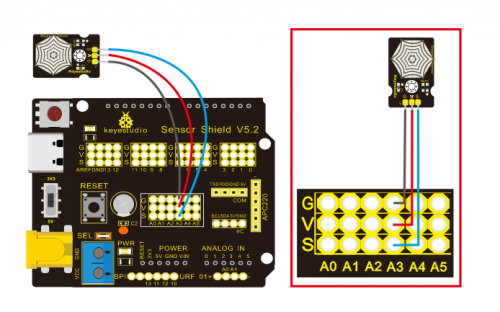
Note: On the sensor shield, the pins G,V and S of steam sensor are connected to G, V and A3; the pins G, V and S of photocell sensor are connected to G, V and A1; the pins G, V and S of yellow LED are linked with G, V and 5; the brown line is linked with G, red wire to V, orange wire to 9.
Test Code:
/*
Keyestudio smart home Kit for Arduino
Project 9
Steam
http://www.keyestudio.com
*/
void setup()
{
Serial.begin(9600); //open serial port, and set baud rate at 9600bps
}
void loop()
{
int val;
val=analogRead(3); //plug vapor sensor into analog port 3
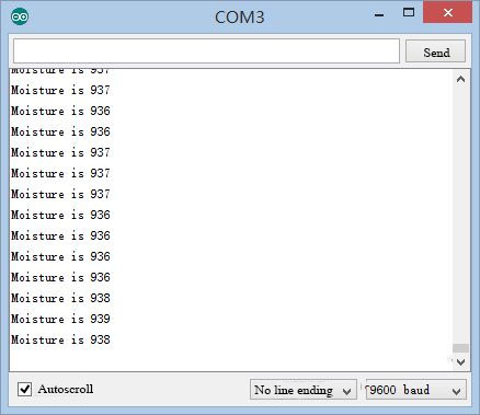
Serial.print("Moisture is ");
Serial.println(val,DEC); //read analog value through serial port printed
delay(100); //delay 100ms
}
Test Result:
When detecting different degrees of humidity, the sensor will get the feedback of different current value. Shown as the following picture.
When the sensor detects the steam of boiled water, the moisture value is displayed on serial monitor of Arduino software.
Project 10: PIR Motion Sensor
Description
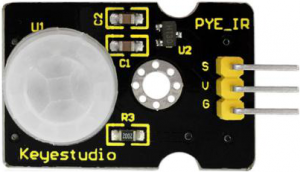
The Pyroelectric infrared motion sensor can detect infrared signals from a moving person or moving animal, and output switching signals. It can be applied to a variety of occasions to detect the movement of human body. Conventional pyroelectric infrared sensors are much more bigger, with complex circuit and lower reliability. Now we launch this new pyroelectric infrared motion sensor, specially designed for Arduino. This sensor integrates an integrated digital pyroelectric infrared sensor, and the connection pins. It features higher reliability, lower power consumption and simpler peripheral circuit.
Specifications:
- Input voltage: DC 3.3V ~ 18V
- Working current: 15uA
- Working temperature: -20 ~ 85 degrees Celsius
- Output voltage: high 3 V, low 0 V
- Output delay time (high level): about 2.3 to 3 seconds
- Detection angle: about 100 °
- Detection distance: 3-4 meters
- Output indicator LED (high-level light)
- Pin limit current: 100mA
Special note:
- 1. The maximum distance is 3-4 meters during testing.
- 2. When testing, first open the white lens, you can see the rectangular sensing part. When the long line of the rectangular sensing part is parallel to the ground, the distance is the best.
- 3. When testing, the sensor needs to be covered with white lens, otherwise it will affect the distance.
- 4. The distance is best at 25℃, and the detection distance is shortened when it exceeds 30℃.
- 5. Done powering up and uploading the code, you need to wait 5-10 seconds then start testing, otherwise it is not sensitive.
Equipment:
Connection Diagram:
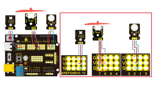
Note: On the shield, the G, V and S of PIR motion sensor are connected to G, V and 2; the GND, VCC, INA and INB of fan module are separately connected to G,V,7,6. The pin G, V and S of LED module are linked with G, V and 13.
Test Code:
/*
Keyestudio smart home Kit for Arduino
Project 10
PIR
http://www.keyestudio.com
*/

void setup () {
   Serial.begin (9600); // open serial port, and set baud rate at 9600bps
   pinMode (2, INPUT); // Define PIR as input in D2
   Serial.begin (9600);
   pinMode (13, OUTPUT); // Define LED as output in D13
   pinMode (7, OUTPUT); // Define D7 as output
   pinMode (6, OUTPUT); // Define D6 as output
}

void loop () {
   Serial.println (digitalRead (2));
   delay (500); // Delay 500ms
   if (digitalRead (2) == 1) // If someone is detected walking
  {
     digitalWrite (13, HIGH); // LED light is on
     digitalWrite (7, HIGH);
     analogWrite (6,150); // Fan rotates

   } else // If no person is detected walking
{
     digitalWrite (13, LOW); // LED light is not on
     digitalWrite (7, LOW);
     analogWrite (6,0); // The fan does not rotate
   }}
//
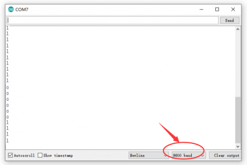
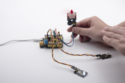
Test Result:
Upload test code, open serial monitor, and set baud rate to 9600. If PIR motion sensor detects the people around, the serial monitor displays “1”, the D13 and white LED light on at same time, fan rotates. If there is no person around, the serial monitor shows “0”, the D13 indicator and white LED are off. The fan stops rotating.
Project 11: Analog(MQ-2)Sensor
Description
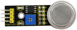
This gas sensor is used for household gas leak alarms, industrial combustible gas alarms and portable gas detection instruments. And it is suitable for the detection of liquefied gas, benzene, alkane, alcohol, hydrogen, etc., and widely used in various fire alarm systems. The MQ-2 smoke sensor can be accurately a multi-gas detector, and has the advantages of high sensitivity, fast response, good stability, long life, and simple drive circuit.
It can detect the concentration of flammable gas and smoke in the range of 300~10000ppm.Meanwhile, it has high sensitivity to natural gas, liquefied petroleum gas and other smoke, especially to alkanes smoke.
It must be heated for a period of time before using the smoke sensor, otherwise the output resistance and voltage are not accurate. However, the heating voltage should not be too high, otherwise it will cause my internal signal line to blow.
It is belongs to the tin dioxide semiconductor gas-sensitive material, and belongs to the surface ion type N-type semiconductor. At a certain temperature, tin dioxide adsorbs oxygen in the air and forms negative ion adsorption of oxygen, reducing the electron density in the semiconductor, thereby increasing its resistance value. When in contact with flammable gas in the air and smog, if the potential barrier at the grain boundary is adjusted by the smog, it will cause the surface conductivity to change. With this, information about the presence of smoke or flammable gas can be obtained. The greater the concentration of smoke or flammable gas in the air, the greater the conductivity, and the lower the output resistance, the larger the analog signal output. The sensor comes with a positioning hole, which is convenient for you to fix the sensor to other devices. In addition, the sensitivity can be adjusted by rotating the potentiometer.
Specifications:
- Working voltage: 3.3-5V (DC)
- Interface: 4 pins (VCC, GND, D0, A0)
- Output signal: digital signal and analog signal
- Weight: 7.5g
Equipment:
Connection Diagram:
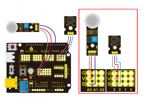
Note: On the shield, the pin GND, VCC, D0 and A0 of gas sensor are linked with pin GND, VCC, D0 and A0. Pin GND, VCC, INA and INB of fan module are connected to G,V, 7 and 6. The pin G,V and S of passive buzzer are connected to G,V and 3; the pin G, V and S of yellow LED are connected to G,V and 5.
Test Code:
/*
Keyestudio smart home Kit for Arduino
Project 11
Gas
http://www.keyestudio.com
*/
int MQ2 = A0; // Define MQ2 gas sensor pin at A0
int val = 0; // declare variable
int buzzer = 3; // Define the buzzer pin at D3
void setup ()
{
pinMode (MQ2, INPUT); // MQ2 gas sensor as input
Serial.begin (9600); // Set the serial port baud rate to 9600
pinMode (buzzer, OUTPUT); // Set the digital IO pin mode for output
}
void loop ()
{
val = analogRead (MQ2); // Read the voltage value of A0 port and assign it to val
Serial.println (val); // Serial port sends val value
if (val> 450)
{
tone (buzzer, 589);
delay(300);
}
else
{
noTone (buzzer);
}
}
//
Test Result:
Upload test code, wire according to connection diagram and power on. When gas sensor detects the flammable gas, passive buzzer will sound, fan will rotate and yellow LED will be on; when there is no flammable gas, the passive buzzer won’t sound, the fan won’t rotate and yellow LED will be off.
Project 12: 1602 LCD Display
Description
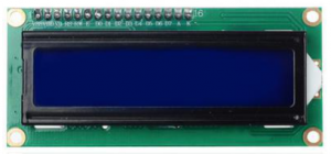
With I2C communication module, this is a display module that can show 2 lines with 16 characters per line.
It shows blue background and white word and connects to I2C interface of MCU, which highly save the MCU resources.
On the back of LCD display, there is a blue potentiometer for adjusting the backlight. The communication address defaults to 0x27.
The original 1602 LCD can start and run with 7 IO ports, but ours is built with Arduino IIC/I2C interface, saving 5 IO ports. Alternatively, the module comes with 4 positioning holes with a diameter of 3mm, which is convenient for you to fix on other devices.
Notice that when the screen gets brighter or darker, the characters will become more visible or less visible.
Specifications:
- I2C address: 0x27
- Backlight (blue, white)
- Power supply voltage: 5V
- Adjustable contrast
- GND: A pin that connects to ground
- VCC: A pin that connects to a +5V power supply
- SDA: A pin that connects to analog port A4 for IIC communication
- SCL: A pin that connects to analog port A5 for IIC communication
Equipment:
Connection Diagram:
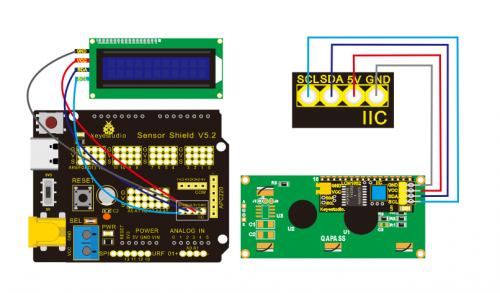
Note: there are pin GND, VCC, SDA and SCL on 1602LCD module. GND is linked with GND(-)of IIC communication, VCC is connected to 5V(+), SDA to SDA, SCL to SCL.
Test Code:
/*
Keyestudio smart home Kit for Arduino
Project 12
1602 LCD
http://www.keyestudio.com
*/
#include <Wire.h>
#include <LiquidCrystal_I2C.h>
LiquidCrystal_I2C lcd (0x27,16,2); // set the LCD address to 0x27 for a16 chars and 2 line display
void setup ()
{
lcd.init (); // initialize the lcd
lcd.init (); // Print a message to the LCD.
lcd.backlight ();
lcd.setCursor (3,0);
lcd.print ("Hello, world!"); // LED print hello, world!
lcd.setCursor (2,1);
lcd.print ("keyestudio!"); // LED print keyestudio!
}
void loop ()
{
}
//
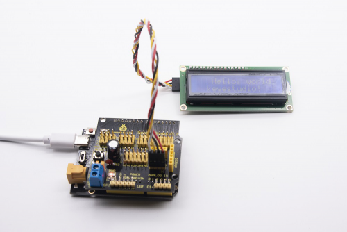
Test Result:
After connection and uploading sample code, the first line on LCD prints «Hello, world!», second line prints «keyestudio!», with a potentiometer to adjust LCD backlight.
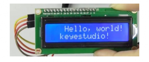
Note: Wire according to connection diagram, upload the code and after power-on, when the display doesn’t show characters, you can adjust the potentiometer behind the 1602LCD and backlight to make the 1602LCD display the corresponding character string.
Project 13: Soil Humidity Sensor
Description
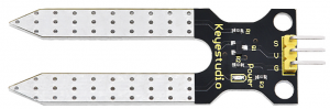
This is a simple soil humidity sensor aims to detect the soil humidity.
If the soil is in lack of water, the analog value output by the sensor will decrease; otherwise, it will increase. If you use this sensor to make an automatic watering device, it can detect whether your botany is thirsty to prevent it from withering when you go out.
Using the sensor with Arduino controller makes your plant more comfortable and your garden smarter. The soil humidity sensor module is not as complicated as you might think, and if you need to detect the soil in your project, it will be your best choice. The sensor is set with two probes inserted into the soil, then with the current go through the soil, the sensor will get resistance value by reading the current changes between the two probes and convert such resistance value into moisture content. The higher moisture (less resistance), the higher conductivity the soil has. Insert it into the soil and then use the AD converter to read it. With the help of this sensor, the plant can remind of you: I need water.
Specification
- Power Supply Voltage: 3.3V or 5V
- Working Current: ≤ 20mA
- Output Voltage: 0-2.3V (When the sensor is totally immersed in water, the voltage will be 2.3V) the higher humidity, the higher the output voltage
- Sensor type: Analog output
- Interface definition: S- signal, G- GND, V — VCC
- Packaging : Electrostatic bag sealing
- Size: 63 * 20 * 8mm
- Weight: 2.5g
Equipment
Connection Diagram
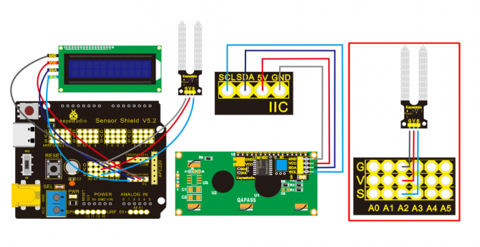
Note: On the shield, the pin G, V and S of soil humidity sensor are connected to G, V and A2; GND of 1602LCD is linked with GND of ICC communication, VCC is connected to 5V(+), SDA to SDA, SCL to SCL.
Test Code:
/*
Keyestudio smart home Kit for Arduino
Project 13
Soil Humidity
http://www.keyestudio.com
*/
#include <Wire.h>
#include <LiquidCrystal_I2C.h>
volatile int value;
LiquidCrystal_I2C mylcd (0x27,16,2); // set the LCD address to 0x27 for a16 chars and 2 line display
void setup () {
  Serial.begin (9600); // Set the serial port baud rate to 9600
  value = 0;
  mylcd.init ();
  mylcd.backlight (); // Light up the backlight
  mylcd.clear (); // Clear the screen
  Serial.begin (9600); // Set the serial port baud rate to 9600
  pinMode (A2, INPUT); // Soil sensor is at A2, the mode is input
}
void loop () {
  Serial.print ("Soil moisture value:"); // Print the value of soil moisture
  Serial.print ("");
  Serial.println (value);
  delay (500); // Delay 0.5S
  value = analogRead (A2); // Read the value of the soil sensor
  if (value <300) // If the value is less than 300
{
    mylcd.clear (); // clear screen
    mylcd.setCursor (0, 0);
    mylcd.print ("value:"); //
    mylcd.setCursor (6, 0);
    mylcd.print (value);
    mylcd.setCursor (0, 1);
    mylcd.print ("dry soil"); // LCD screen print dry soil
    delay (300); // Delay 0.3S
  }
  else if ((value>=300) && (value <= 700)) // If the value is greater than 300 and less than 700
 {
    mylcd.clear (); //clear screen
    mylcd.setCursor (0, 0);
    mylcd.print ("value:");
    mylcd.setCursor (6, 0);
    mylcd.print (value);
    mylcd.setCursor (0, 1);
    mylcd.print ("humid soil"); // LCD screen printing humid soil
    delay (300); // Delay 0.3S
  } else if (value> 700) // If the value is greater than 700
 {
    mylcd.clear ();//clear screen
    mylcd.setCursor (0, 0);
    mylcd.print ("value:");
    mylcd.setCursor (6, 0);
    mylcd.print (value);
    mylcd.setCursor (0, 1);
    mylcd.print ("in water"); /// LCD screen printing in water
    delay (300); // Delay 0.3S
  }}
//
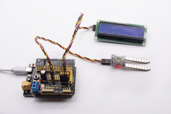
Test Result:
Connect according to wiring diagram, and burn the program and power on. Open the serial monitor and insert the soil humidity sensor into the soil. The greater the humidity is, the bigger the number, in the range of 0-1023. The soil sensor is inserted into the soil and water with different humidity, and the 1602LCD displays the corresponding value.
Project 14: Bluetooth Test
In 20th century, technology has changed our life. People can work at home with wireless device like mouse, earphone, printer and speaker, which highly enhances our life standard.
Bluetooth can make work at home easily, as well as the entertainment. Users can control wirelessly the audio file from PC or Apple iPod within 30 inches. Bluetooth technology can also be used in adapters, allowing people to share their daily life with friends from internet and social media.
Bluetooth Remote Control
Bluetooth technology is a wireless standard technology that enables short-distance data exchange between fixed devices, mobile devices, and building personal area networks (using UHF radio waves in the ISM band of 2.4 to 2.485 GHz).
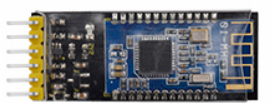
This kit is equipped with the HM-10 Bluetooth module, which is a master-slave machine. When use as the Host, it can send commands to the slave actively; when use as the Slave, it can only receive commands from the host.
The HM-10 Bluetooth module supports the Bluetooth 4.0 protocol, which not only supports Android mobile, but also supports iOS system.
In the experiment, we default use the HM-10 Bluetooth module as a Slave and the cellphone as a Host. We install the Bluetooth APP on the mobile phone, connecting the Bluetooth module; finally use the Bluetooth APP to control the parts of smart home kit.
We also provide you with 2 types of mobile APP, for Android and iOS system.
Parameters of HM-10 Bluetooth Module:
- Bluetooth protocol: Bluetooth Specification V4.0 BLE
- No byte limit in serial port Transceiving
- In open environment, realize 100m ultra-distance communication with iphone4s
- USB protocol: USB V2.0
- Working frequency: 2.4GHz ISM band
- Modulation method: GFSK(Gaussian Frequency Shift Keying)
- Transmission power: -23dbm, -6dbm, 0dbm, 6dbm, can be modified by AT command.
- Sensitivity: ≤-84dBm at 0.1% BER
- Transmission rate: Asynchronous: 6K bytes ; Synchronous: 6k Bytes
- Security feature: Authentication and encryption
- Supporting service: Central & Peripheral UUID FFE0, FFE1
- Power consumption: Auto sleep mode, stand by current 400uA~800uA, 8.5mA during transmission.
- Power supply: 5V DC
- Working temperature: –5 to +65 Centigrade
Using Bluetooth APP
Description:
In the previous lesson, we’ve introduced the basic parameter principle of HM-10 Bluetooth module. In this project, let’s show you how to use the HM-10 Bluetooth module. In order to efficiently control this kit by HM-10 Bluetooth module, we specially designed an APP, as shown below.
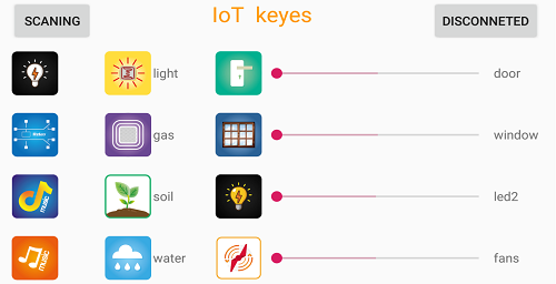
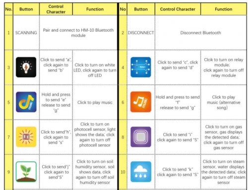
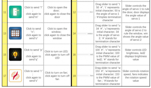
There are twelve control buttons and four sliders on App. When we connect the HM-10 Bluetooth module and app, only press control button of APP, and the Bluetooth of cellphone sends a control character. The Bluetooth module will receive a corresponding control character. When programming, we set the corresponding function of each sensor or module according to the corresponding key control character. Next, let’s test 12 buttons on app.
APP for Android mobile:
Note: Allow APP to access “location” in settings of your cellphone when connecting to Bluetooth module, otherwise, Bluetooth may not be connected.
Enter google play,search “keyes IoT”,if you can’t search it on app store, please download app in the following link:
https://play.google.com/store/apps/details?id=com.keyestudio.iot_keyes
After installing and open the app  ,the interface pops up as below:
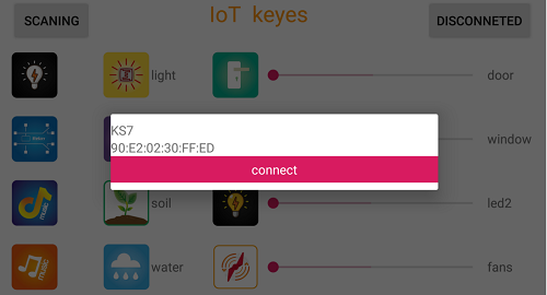
Upload code and power on, Led of Bluetooth module blinks. Start Bluetooth and open App to click “CONNECT” to connect.
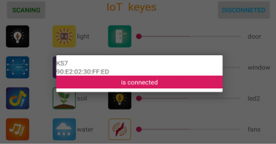
Click to “Connect”, Bluetooth is connected successfully. As shown below, the LED of Bluetooth module is normally on.
For IOS system:
(1) Open App Store 
(2) Search “IoT keyes”on APP Store,then click “downlaod”.
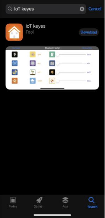
(3)After installing successfully and open ,the interface is shown below:
(4)Upload the test code successfully, insert the Bluetooth module and power on. LED of Bluetooth module is flashing. Start Bluetooth on cellphone, then click “connect” on the left to search Bluetooth and pair. After paring successfully, the LED of Bluetooth module is on.
Note: Remove the Bluetooth module please, when uploading the test code. Otherwise, the program will fail to upload. Connect the Bluetooth and Bluetooth module to pair after uploading the test code.
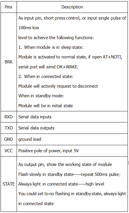
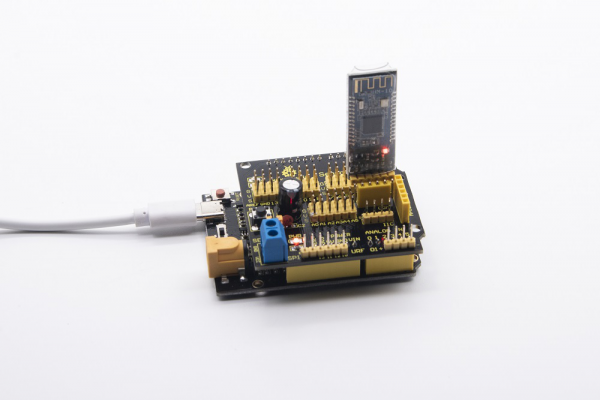
4.Connection Diagram
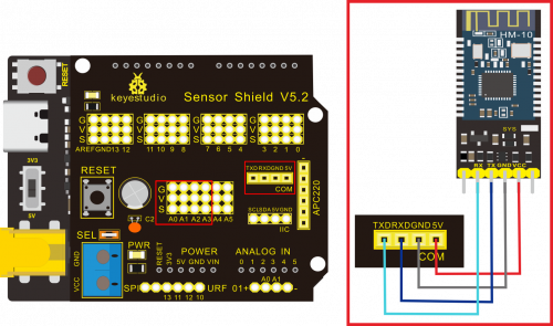
Note: On the sensor expansion board, the RXD, TXD, GND, and VCC of the Bluetooth module are respectively connected to TXD, RXD, GND, and 5V, and the STATE and BRK pins of the Bluetooth module do not need to be connected. Connect the power supply.
Test Code:
/*
Keyestudio smart home Kit for Arduino
Project 14
Bluetooth
http://www.keyestudio.com
*/
char val;
void setup()
{
Serial.begin(9600);// Set the serial port baud rate to 9600
}
void loop()
{
while (Serial.available()>0)
{
val=Serial.read();// Read the value sent by Bluetooth
Serial.print(val);// The serial port prints the read value
}
}
//
Key function on app:
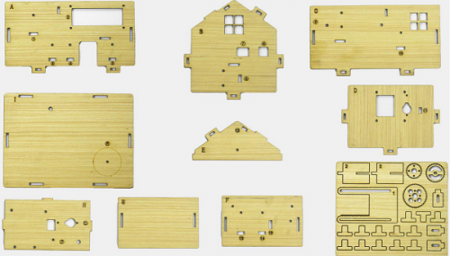
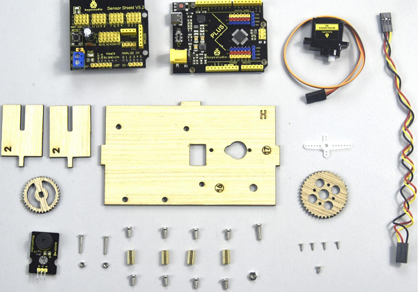
Assembled Guide
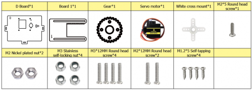
Check the board A~I and parts firstly
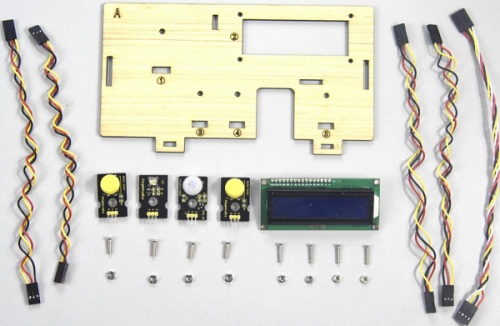
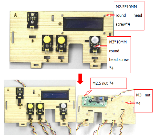
Step 1: Install sensors of A board
Prepare A board*1, M3*10MM round screw*4,M3 nickel plated nut*4;M2.5*10MM round screw*4,button sensor*2, white LED*1, PIR motion sensor*1, LCD1602 display*1, 4pin F-F dupont line*1, 3pin F-F dupont line*4
- a.Fix white LED, 2 button sensors and PIR motion sensor on the corresponding area of the A board with 4pcs M3*10MM round head screws and 4pcs M3 nuts.
- b.Then install LCD1602 display on A board with 4pcs M2.5*10MM round head screws and 4pcs M2.5 nuts.
- c.Connect them with 3pin and 4pin dupont lines.
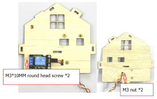
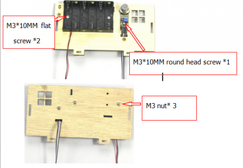
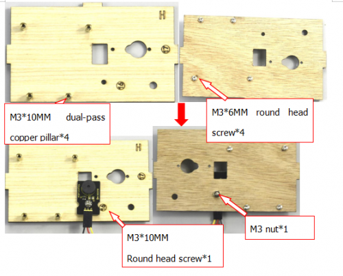
Step 2: Install the sensor of B board
Prepare a B board,a 3pin F-F Dupont line,2pcs M3*10MM round head screws,2pcs M3 nickel plated nuts and a relay module
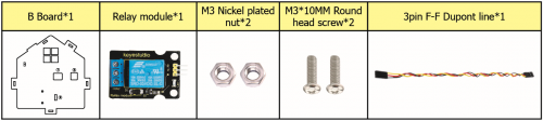
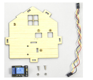
Assemble the relay module on B board with 2 pcs M3*10MM screws and 2pcs M3 nuts, link them together with 3pin dupont line
Step 3: Fix A board and B board together with a “T” bolt.

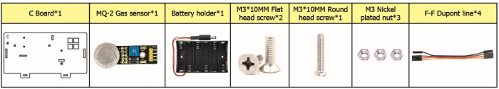
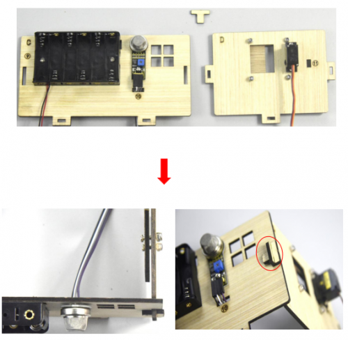
Step 4: Assemble the sensors and battery holder of C board
Prepare a C board,MQ-2 gas sensor,battery holder,2pcs M3*10MM flat head screws,a M3*10MM round head screw,3pcs M3 nickel plated nuts and 4 F-F dupont lines.
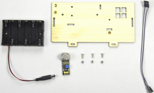
- A.Fix the battery holder on C board with 2pcs M3*10MM flat head screws and 2 pcs M2 nuts
- B.Then install the MQ-2 gas sensor on the corresponding area of C board with a M3*10MM round head screw and a M3 nut.
- C.Connect them with 4 female to female dupont lines
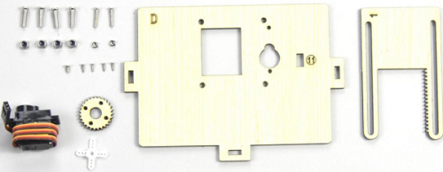
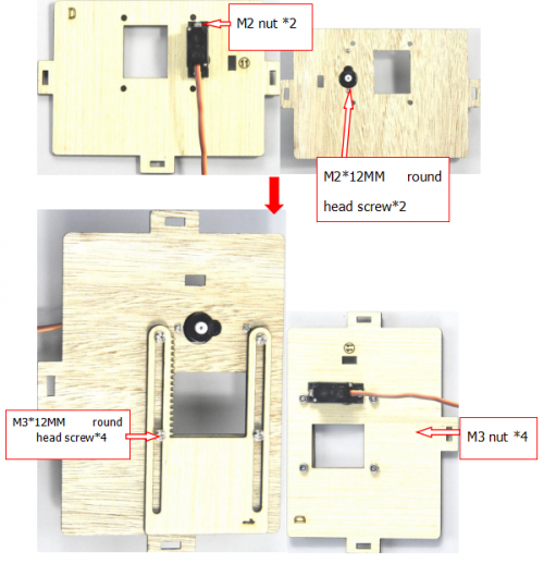
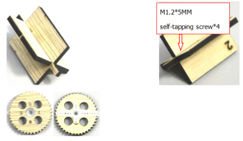
Step 5: Install the sensors and parts of D board
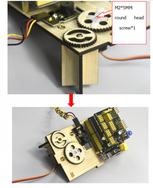
Prepare a servo, 4pcs M1.2*5 self-tapping screws,a white cross mount(included in servo),a M2*5 round head screw(included in servo),2pcs M2*12MM round head screws,2pcs M2 nickel plated nuts,4pcs M3*12MM round head screws,4pcs M3 stainless self-locking nuts,a D board,a gear, a board1.
Rotate servo to 90° before installing, connect servo to keyestudio PLUS control board; upload test code on control board and make servo rotate to 90°
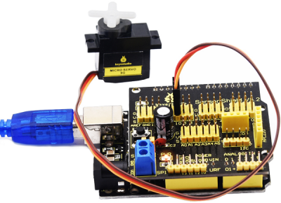
Test Code:
#include <Servo.h>
Servo servo_10;

void setup(){
  servo_10.attach(10);
}
void loop(){
  servo_10.write(90);
  delay(500);}
Upload the test code successfully, the servo rotates to 90°
- A.Fix servo on the corresponding area on D board with 2pcs M2*12MM round head screws and 2 M2 nuts.
- B.Then install the square board 1 on the D board with 4pcs M3*12MM round head screws and 4 M3 self-locking nuts.
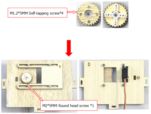
Fix the white cross mount on the gear with 4pcs M1.2*5MM self-tapping screws, and mount the gear on the servo motor with 1 M2*5MM round head screw.
Step 6: Assemble C board with D board by a “T” type bolt.
Step 7: install the sensor of E board
Prepare a yellow LED module, a E board, a M3*10MM round head screw, a M3 nickel plated nut and a 3pin F-F Dupont line
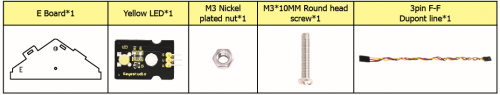
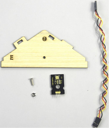
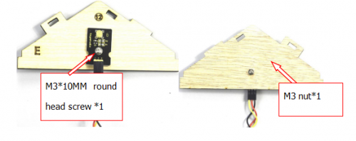
Mount the yellow LED on the corresponding area of E board with 1 M3*10MM round head screw and 1 M3 nickel plated nut,then connect with a 3pin dupont line.
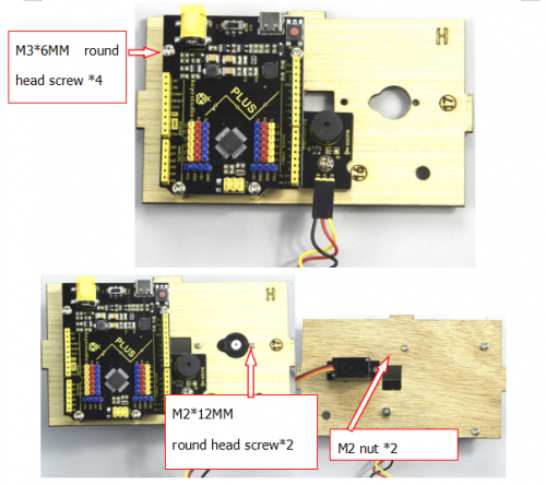
Step 8: Install control board, sensors and parts of H board
Prepare a servo, a passive buzzer, 4pcs M1.2*5 self-tapping screws, a white cross mount(included in servo), a M2*5 screw( included in servo), 2pcs M2*12MM round head screws, 2pcs M2 nickel plated nuts, a M3*10MM round screw, a M3 nickel plated nut, 8pcs M3*6MM round head screws, 4pcs M3*10MM dual-pass copper pillars, a Keyestudio PLUS control board,a sensor shield, a 3pinF-F Dupont line, a board E, 2 gears and 2pcs board 2.
- A.Mount 4pcs dual-pass copper pillars on the H board with 4pcs M3*6MM screws
- B.Then fix the passive buzzer on H board with 1 M3*10MM round head screw and 1 MS nut.
- C.Connect them with a 3pin female to female dupont wire
Rotate the servo to 90° before installing, the method is same as the step 6.
Fix the 4pcs M3*10MM copper pillars on the keyestudio PLUS control board with 4 M3*6MM round head screws, then fix the servo on the corresponding area of H board with 2 M2*12MM round head screws and 2 M2 nuts.
Assemble 2pcs board 2 together, then fix white cross mount on the gear with 4pcs M1.2*5 self-tapping screws
Fix the gear with white cross mount on the black servo by 1 M2*5MM screw(included in servo), then install the combination of 2pcs board 2 and another servo on the corresponding area of H board, finally stack the sensor shield on the keyestudio PLUS control board.
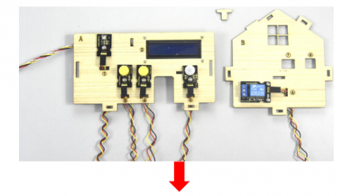
Step 9: Assemble A, B, C, D, E and H board together, then fix them with 2 “T” type bolts.
(Note: the power interface of PLUS control board is aligned with the hole ⑧ on board B, and the interface of USB cable is aligned with the hole ⑦ on board B)
Step 10: Install the sensor of F board
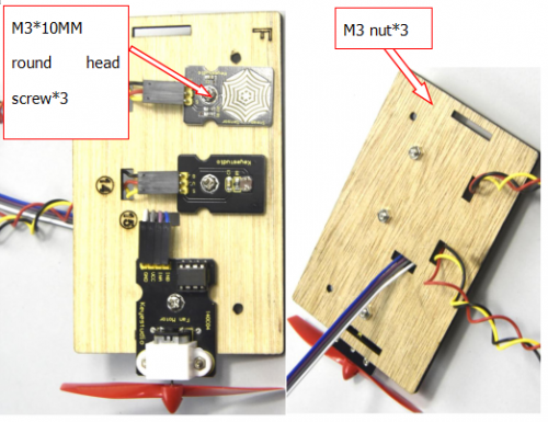
Prepare a steam sensor, a photocell sensor, a fan module(with fan), a board F, 2pcs 3pinF-F Dupont line, 4pcs F-F dupont lines, 3pcs M3*10MM round head screws and 3pcs M3 nickel plated nuts.
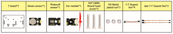
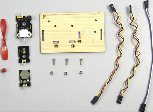
Separately fix steam sensor, photocell sensor and fan module on the F board with 3pcs M3*10MM round head screws and 3pcs M3 nuts, then connect them with 3pin and 4pin dupont lines.
Step 11: Connect sensor/module
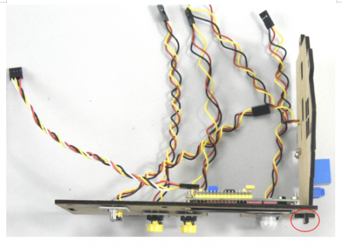
Connect one end of 3pin dupont line to the pin of soil humidity sensor, then link all sensors to sensor shield. (fix 2 servo and make dupont wire go through the holes of board)
Insert the Bluetooth module into sensor shield, then fix the F board with 2 M3*10MM round head screws, 2 M3 nuts and 2 pcs parts with holes in the middle, mount G board well with 2 “T” type bolts.
Step 12: Assemble the kit
Fix the board I with 6 “T” bolts
Project 15:Multi-purpose Smart Home Kit
Description
In the previous projects, we introduce how to use sensors, modules and HM-10 Bluetooth module. For this lesson, we will perform all functions
We will achieve the effect as follows:
- Photocell sensor, PIR motion sensor and LED. When at night, someone passes by, LED is on; nobody is around, the LED is off.
- There are 1602LCD display, 2 buttons, 1 servo on the board. Press button1 to enter the password(you can set password in the test code), the 1602LCD will show “*”, then press button2 to “ensure”. If the password is correct, the 1602LCD will show “open”, the door will be open. However, if the password is wrong, the “error” pops up , after 2s, “error” will turn into “again” , you can enter password again.
The door will be closed when PIR motion sensor doesn’t detect people around. What’s more, press and hold button2, buzzer will sound, LCD displays “wait”.(If the password is right, the servo will rotate to 180°, otherwise,the servo don’t rotate)
Note: The correct password is ”. — — . — .” which means that short press button1, long press button1, long press button1, short press button1, long press button1, short press button1.
”- ”means long press button1, ”.”means short press button1
Equipment:
Connection Diagram:
Test Code:
//call the relevant library file
#include <Servo.h>
#include <Wire.h>
#include <LiquidCrystal_I2C.h>
//Set the communication address of I2C to 0x27, display 16 characters every line, two lines in total
LiquidCrystal_I2C mylcd(0x27, 16, 2);

//set ports of two servos to digital 9 and 10
Servo servo_10;
Servo servo_9;

volatile int btn1_num;//set variable btn1_num
volatile int btn2_num;//set variable btn2_num
volatile int button1;//set variable button1
volatile int button2;//set variable button2
String fans_char;//string type variable fans_char
volatile int fans_val;//set variable fans_char
volatile int flag;//set variable flag
volatile int flag2;//set variable flag2
volatile int flag3;//set variable flag3
volatile int gas;//set variable gas
volatile int infrar;//set variable infrar
String led2;//string type variable led2
volatile int light;//set variable light
String pass;//string type variable pass
String passwd;//string type variable passwd

String servo1;//string type variable servo1
volatile int servo1_angle;//set variable light
String servo2;//string type variable servo2
volatile int servo2_angle;//set variable servo2_angle

volatile int soil;//set variable soil
volatile int val;//set variable val
volatile int value_led2;//set variable value_led2
volatile int water;//set variable water

int length;
int tonepin = 3; //set the signal end of passive buzzer to digital 3
//define name of every sound frequency
#define D0 -1
#define D1 262
#define D2 293
#define D3 329
#define D4 349
#define D5 392
#define D6 440
#define D7 494
#define M1 523
#define M2 586
#define M3 658
#define M4 697
#define M5 783
#define M6 879
#define M7 987
#define H1 1045
#define H2 1171
#define H3 1316
#define H4 1393
#define H5 1563
#define H6 1755
#define H7 1971

#define WHOLE 1
#define HALF 0.5
#define QUARTER 0.25
#define EIGHTH 0.25
#define SIXTEENTH 0.625

//set sound play frequency
int tune[] =
{
  M3, M3, M4, M5,
  M5, M4, M3, M2,
  M1, M1, M2, M3,
  M3, M2, M2,
  M3, M3, M4, M5,
  M5, M4, M3, M2,
  M1, M1, M2, M3,
  M2, M1, M1,
  M2, M2, M3, M1,
  M2, M3, M4, M3, M1,
  M2, M3, M4, M3, M2,
  M1, M2, D5, D0,
  M3, M3, M4, M5,
  M5, M4, M3, M4, M2,
  M1, M1, M2, M3,
  M2, M1, M1
};

//set music beat
float durt[] =
{
  1, 1, 1, 1,
  1, 1, 1, 1,
  1, 1, 1, 1,
  1 + 0.5, 0.5, 1 + 1,
  1, 1, 1, 1,
  1, 1, 1, 1,
  1, 1, 1, 1,
  1 + 0.5, 0.5, 1 + 1,
  1, 1, 1, 1,
  1, 0.5, 0.5, 1, 1,
  1, 0.5, 0.5, 1, 1,
  1, 1, 1, 1,
  1, 1, 1, 1,
  1, 1, 1, 0.5, 0.5,
  1, 1, 1, 1,
  1 + 0.5, 0.5, 1 + 1,
};


void setup() {
  Serial.begin(9600);//set baud rate to 9600

  mylcd.init();
  mylcd.backlight();//initialize LCD
  //LCD shows "passcord:" at first row and column
  mylcd.setCursor(1 - 1, 1 - 1);
  mylcd.print("passcord:");

  servo_9.attach(9);//make servo connect to digital 9
  servo_10.attach(10);//make servo connect to digital 10
  servo_9.write(0);//set servo connected digital 9 to 0°
  servo_10.write(0);//set servo connected digital 10 to 0°
  delay(300);

  pinMode(7, OUTPUT);//set digital 7 to output
  pinMode(6, OUTPUT);//set digital 6 to output
  digitalWrite(7, HIGH); //set digital 7 to high level
  digitalWrite(6, HIGH); //set digital 6 to high level

  pinMode(4, INPUT);//set digital 4 to input
  pinMode(8, INPUT);//set digital 8 to input
  pinMode(2, INPUT);//set digital 2 to input
  pinMode(3, OUTPUT);//set digital 3 to output
  pinMode(A0, INPUT);//set A0 to input
  pinMode(A1, INPUT);//set A1 to input
  pinMode(13, OUTPUT);//set digital 13 to input
  pinMode(A3, INPUT);//set A3 to input
  pinMode(A2, INPUT);//set A2 to input

  pinMode(12, OUTPUT);//set digital 12 to output
  pinMode(5, OUTPUT);//set digital 5 to output
  pinMode(3, OUTPUT);//set digital 3 to output
  length = sizeof(tune) / sizeof(tune[0]); //set the value of length
}

void loop() {
  auto_sensor();
  if (Serial.available() > 0) //serial reads the characters
  {
    val = Serial.read();//set val to character read by serial    Serial.println(val);//output val character in new lines
    pwm_control();
  }
  switch (val) {
    case 'a'://if val is character 'a',program will circulate
      digitalWrite(13, HIGH); //set digital 13 to high level,LED 	lights up
      break;//exit loop
    case 'b'://if val is character 'b',program will circulate
      digitalWrite(13, LOW); //Set digital 13 to low level, LED is off
      break;//exit loop
    case 'c'://if val is character 'c',program will circulate
      digitalWrite(12, HIGH); //set digital 12 to high level,NO of relay is connected to COM
      break;//exit loop
    case 'd'://if val is character 'd',program will circulate
      digitalWrite(12, LOW); //set digital 12 to low level,NO of relay is disconnected to COM

      break;//exit loop
    case 'e'://if val is character 'e',program will circulate
      music1();//play birthday song
      break;//exit loop
    case 'f'://if val is character 'f',program will circulate
      music2();//play ode to joy song
      break;//exit loop
    case 'g'://if val is character 'g',program will circulate
      noTone(3);//set digital 3 to stop playing music
      break;//exit loop
    case 'h'://if val is character 'h',program will circulate
      Serial.println(light);//output the value of variable light in new lines
      delay(100);
      break;//exit loop
    case 'i'://if val is character 'i',program will circulate
      Serial.println(gas);//output the value of variable gas in new lines
      delay(100);
      break;//exit loop
    case 'j'://if val is character 'j',program will circulate
      Serial.println(soil);//output the value of variable soil in new lines
      delay(100);
      break;//exit loop
    case 'k'://if val is character 'k',program will circulate
      Serial.println(water);//output the value of variable water in new lines
      delay(100);
      break;//exit loop
    case 'l'://if val is character 'l',program will circulate
      servo_9.write(180);//set servo connected to digital 9 to 180°
      delay(500);
      break;//exit loop
    case 'm'://if val is character 'm',program will circulate
      servo_9.write(0);;//set servo connected to digital 9 to 0°
      delay(500);
      break;//exit loop
    case 'n'://if val is character 'n',program will circulate
      servo_10.write(180);//set servo connected to digital 10 to 180°
      delay(500);
      break;//exit loop
    case 'o'://if val is character 'o',program will circulate
      servo_10.write(0);//set servo connected to digital 10 to 0°
      delay(500);
      break;//exit loop
    case 'p'://if val is character 'p',program will circulate
      digitalWrite(5, HIGH); //set digital 5 to high level, LED is on
      break;//exit loop
    case 'q'://if val is character 'q',program will circulate
      digitalWrite(5, LOW); // set digital 5 to low level, LED is off
      break;//exit loop
    case 'r'://if val is character 'r',program will circulate
      digitalWrite(7, LOW);
      digitalWrite(6, HIGH); //fan rotates anticlockwise at the fastest speed
      break;//exit loop
    case 's'://if val is character 's',program will circulate
      digitalWrite(7, LOW);
      digitalWrite(6, LOW); //fan stops rotating
      break;//exit loop
  }
}

////////////////////////set birthday song//////////////////////////////////
void birthday()
{
  tone(3, 294); //digital 3 outputs 294HZ sound
  delay(250);//delay in 250ms
  tone(3, 440);
  delay(250);
  tone(3, 392);
  delay(250);
  tone(3, 532);
  delay(250);
  tone(3, 494);
  delay(500);
  tone(3, 392);
  delay(250);
  tone(3, 440);
  delay(250);
  tone(3, 392);
  delay(250);
  tone(3, 587);
  delay(250);
  tone(3, 532);
  delay(500);
  tone(3, 392);
  delay(250);
  tone(3, 784);
  delay(250);
  tone(3, 659);
  delay(250);
  tone(3, 532);
  delay(250);
  tone(3, 494);
  delay(250);
  tone(3, 440);
  delay(250);
  tone(3, 698);
  delay(375);
  tone(3, 659);
  delay(250);
  tone(3, 532);
  delay(250);
  tone(3, 587);
  delay(250);
  tone(3, 532);
  delay(500);
}


//detect gas
void auto_sensor() {
  gas = analogRead(A0);//assign the analog value of A0 to gas
  if (gas > 700) {
//if variable gas>700
    flag = 1;//set variable flag to 1
    while (flag == 1)
      //if flag is 1, program will circulate
    {
      Serial.println("danger");//output "danger" in new lines
      tone(3, 440);
      delay(125);
      delay(100);
      noTone(3);
      delay(100);
      tone(3, 440);
      delay(125);
      delay(100);
      noTone(3);
      delay(300);
      gas = analogRead(A0);//gas analog the value of A0 to gas
      if (gas < 100)  //if variable gas is less than 100
      {
        flag = 0;//set variable flag to 0
        break;//exit loop exist to loop
      }
    }

  } else
    //otherwise
  {
    noTone(3);// digital 3 stops playing music
  }
  light = analogRead(A1);////Assign the analog value of A1 to light
  if (light < 300)//if variable light is less than 300
  {
    infrar = digitalRead(2);//assign the value of digital 2 to infrar
    Serial.println(infrar);//output the value of variable infrar in new lines
    if (infrar == 1)
      // if variable infra is 1
    {
      digitalWrite(13, HIGH); //set digital 13 to high level, LED is on
    } else//Otherwise
    {
      digitalWrite(13, LOW); //set digital 13 to low level, LED is off
    }

  }
  water = analogRead(A3);//assign the analog value of A3 to variable water
  if (water > 800)
    // if variable water is larger than 800
  {
    flag2 = 1;//if variable flag 2 to 1
    while (flag2 == 1)
      // if flag2 is 1, program will circulate
    {
      Serial.println("rain");//output "rain" in new lines
      servo_10.write(180);// set the servo connected to digital 10 to 180°
      delay(300);//delay in 300ms
      delay(100);
      water = analogRead(A3);;//assign the analog value of A3 to variable water
      if (water < 30)// if variable water is less than 30
      {
        flag2 = 0;// set flag2 to 0
        break;//exit loop
      }
    }

  } else//Otherwise
  {
    if (val != 'u' && val != 'n')
      //if val is not equivalent 'u' either 'n'
    {
      servo_10.write(0);//set servo connected to digital 10 to 0°
      delay(10);

    }

  }
  soil = analogRead(A2);//assign the analog value of A2 to variable soil
  if (soil > 50)
    // if variable soil is greater than 50
  {
    flag3 = 1;//set flag3 to 1
    while (flag3 == 1)
      //If set flag3 to 1, program will circulate
    {
      Serial.println("hydropenia ");//output "hydropenia " in new lines
      tone(3, 440);
      delay(125);
      delay(100);
      noTone(3);
      delay(100);
      tone(3, 440);
      delay(125);
      delay(100);
      noTone(3);//digital 3 stops playing sound
      delay(300);
      soil = analogRead(A2);//Assign the analog value of A2 to variable soil
      if (soil < 10)//If variable soil<10
      {
        flag3 = 0;//set flag3 to 0
        break;//exit loop
      }
    }

  } else//Otherwise
  {
    noTone(3);//set digital 3 to stop playing music
  }
  door();//run subroutine
}

void door() {
  button1 = digitalRead(4);// assign the value of digital 4 to button1
  button2 = digitalRead(8);//assign the value of digital 8 to button2


  if (button1 == 0)//if variablebutton1 is 0
  {
    delay(10);//delay in 10ms
    while (button1 == 0) //if variablebutton1 is 0,program will circulate
    {
      button1 = digitalRead(4);// assign the value of digital 4 to button1
      btn1_num = btn1_num + 1;//variable btn1_num plus 1
      delay(100);// delay in 100ms
    }

  }
  if (btn1_num >= 1 && btn1_num < 5) //1≤if variablebtn1_num<5
  {
    Serial.print(".");
    Serial.print("");
    passwd = String(passwd) + String(".");//set passwd
pass = String(pass) + String(".");//set pass
    //LCD shows pass at the first row and column
    mylcd.setCursor(1 - 1, 2 - 1);
    mylcd.print(pass);
  }
  if (btn1_num >= 5)
    //if variablebtn1_num ≥5
  {
    Serial.print("-");
    passwd = String(passwd) + String("-");//Set passwd
    pass = String(pass) + String("-");//set pass
    //LCD shows pass at the first row and column
    mylcd.setCursor(1 - 1, 2 - 1);
    mylcd.print(pass);

  }
  if (button2 == 0) //if variablebutton2 is 0
  {
    delay(10);
    if (button2 == 0)//if variablebutton2 is 0
    {
      if (passwd == ".--.-.")//if passwd is ".--.-."
      {
        mylcd.clear();//clear LCD screen
        //LCD shows "open!" at first character on second row
        mylcd.setCursor(1 - 1, 2 - 1);
        mylcd.print("open!");
        servo_9.write(100);//set servo connected to digital 9 to 100°
        delay(300);
        delay(5000);
        passwd = "";
        pass = "";
        mylcd.clear();//clear LCD screen
        //LCD shows "password:"at first character on first row
        mylcd.setCursor(1 - 1, 1 - 1);
        mylcd.print("password:");

      } else //Otherwise
      {
        mylcd.clear();//clear LCD screen
        //LCD shows "error!"at first character on first row
        mylcd.setCursor(1 - 1, 1 - 1);
        mylcd.print("error!");
        passwd = "";
        pass = "";
        delay(2000);
        //LCD shows "again" at first character on first row
        mylcd.setCursor(1 - 1, 1 - 1);
        mylcd.print("again");
      }
    }
  }
  infrar = digitalRead(2);//assign the value of digital 2 to infrar
  if (infrar == 0 && (val != 'l' && val != 't'))
    //if variable infrar is 0 and val is not 'l' either 't'
  {
    servo_9.write(0);//set servo connected to digital 9 to 0°
    delay(50);
  }
  if (button2 == 0)//if variablebutton2 is 0
  {
    delay(10);
    while (button2 == 0) //if variablebutton2 is 0,program will circulate
    {
      button2 = digitalRead(8);//assign the value of digital 8 to button2
      btn2_num = btn2_num + 1;//variable btn2_num plus 1
      delay(100);
      if (btn2_num >= 15)//if variablebtn2_num ≥15
      {
        tone(3, 532);
        delay(125);
        mylcd.clear();//clear LCD screen
        //LCD shows "password:" at the first character on first row
        mylcd.setCursor(1 - 1, 1 - 1);
        mylcd.print("password:");
        //LCD shows "wait" at the first character on first row
        mylcd.setCursor(1 - 1, 1 - 1);
        mylcd.print("wait");
      } else//Otherwise
      {
        noTone(3);//digital 3 stops playing music
      }
    }

  }
  btn1_num = 0;//set btn1_num to 0
  btn2_num = 0;//set btn2_num to 0
}

// Birthday song
void music1() {
  birthday();
}
//Ode to joy
void music2() {
  Ode_to_Joy();
}
void Ode_to_Joy()//play Ode to joy song
{
  for (int x = 0; x < length; x++)
  {
    tone(tonepin, tune[x]);
    delay(300 * durt[x]);
  }
}

//PWM control
void pwm_control() {
  switch (val)
  {
    case 't'://if val is 't',program will circulate
      servo1 = Serial.readStringUntil('#');
      servo1_angle = String(servo1).toInt();
      servo_9.write(servo1_angle);//set the angle of servo connected to digital 9 to servo1_angle
      delay(300);
      break;//exit loop
    case 'u'://if val is 'u',program will circulate
      servo2 = Serial.readStringUntil('#');
      servo2_angle = String(servo2).toInt();
      servo_10.write(servo2_angle);//set the angle of servo connected to digital 10 to servo2_angle
      delay(300);
      break;//exit loop
    case 'v'://if val is 'v',program will circulate
      led2 = Serial.readStringUntil('#');
      value_led2 = String(led2).toInt();
      analogWrite(5, value_led2); //PWM value of digital 5 is value_led2
      break;//exit loop
    case 'w'://if val is 'w',program will circulate
      fans_char = Serial.readStringUntil('#');
      fans_val = String(fans_char).toInt();
      digitalWrite(7, LOW);
      analogWrite(6, fans_val); //set PWM value of digital 6 to fans_val,the larger the value, the faster the fan
      break;//exit loop
  }
}
Upload the code and see the result!
Note: Remove the Bluetooth module please, when uploading the test code. Otherwise, the program will fail to upload. Connect the Bluetooth and Bluetooth module to pair after uploading the test code.
Test Result
Upload the test code, stack expansion board on PLUS control board, and power on. After pairing and connecting Bluetooth successfully, we can control the smart home through app.
- Wiki page: https://wiki.keyestudio.com/Main_Page
- Official website: https://keyestudio.com/
- Kidsbits website: https://wiki.kidsbits.cc/
More details about video, product file, software downlod, refer to the following link please
- https://fs.keyestudio.com/KS0085
Buy From
- [ Official website: ]
- [ Shop on aliexpress store]

1.Overview:
This Smart Home Learning Kit based on the Arduino platform is newly rolled out by Keyestudio DIY Robot Co. Ltd.
It simulates the real smart home and demonstrates the cozy and comfortable life for people.
In fact, the logic programming, an invisible hand, controls everything in smart home: it turns on the air conditioner, boots up the water heater, secures your home with an electronic lock, and sets your LED lights and smart curtains to turn on automatically when you get home. Meanwhile, the intelligent lighting system allows you to create a comfortable, tranquil atmosphere. Everything is finished by a remote control or your own cellphone.
As Bill Gates puts it, “In the near future, a house without a smart home system will be as unfashionable as a home without Internet access today.”
So, go ahead and get started; let’s build this amazing analog smart home.

2.Kit list
After getting this smart home kit, we need to make sure that there are not missing components.
|
# |
Name |
QTY |
Picture |
|---|---|---|---|
|
1 |
Keyestudio PLUS Control Board(Compatible with Arduino UNO ) |
1 |
 |
|
2 |
Keyestudio Sensor Shield V 5.2 |
1 |
 |
|
3 |
Wooden Board*10 T=3MM |
1 |
 |
|
4 |
White LED Module |
1 |
 |
|
5 |
Yellow LED Module |
1 |
 |
|
6 |
Button Sensor |
2 |
 |
|
7 |
Photocell Sensor |
1 |
 |
|
8 |
PIR Motion Sensor |
1 |
 |
|
9 |
MQ-2 Gas Sensor |
1 |
 |
|
10 |
Relay Module |
1 |
 |
|
11 |
Bluetooth HM-10 Module |
1 |
 |
|
12 |
Passive Buzzer Sensor |
1 |
 |
|
13 |
Fan module |
1 |
 |
|
14 |
Steam Sensor |
1 |
 |
|
15 |
Servo Motor |
2 |
 |
|
16 |
LCD1602 Display Module |
1 |
 |
|
17 |
Soil Humidity Sensor |
1 |
 |
|
18 |
USB Cable |
1 |
 |
|
19 |
Female to Female Dupont Cables |
40 |
 |
|
20 |
Male to female Dupont Cables |
6 |
 |
|
21 |
M3 Nickel Plated Nuts |
25 |
|
|
22 |
M2*12MM Round Head Screws |
6 |
 |
|
23 |
M2 Nickel Plated Nuts |
6 |
 |
|
24 |
M3*10MM Dual-pass Copper Bush |
4 |
 |
|
25 |
M3*6MM Round Head Screws |
8 |
 |
|
26 |
M3 304 Stainless Steel Self-locking Nuts |
4 |
 |
|
27 |
M3*10MM Round Head Screws |
20 |
 |
|
28 |
M2.5*10MM Round Head Screws |
6 |
 |
|
29 |
M2.5 Nickel Plated Nuts |
6 |
 |
|
30 |
M3*12MM Round Head Screws |
6 |
 |
|
31 |
M3*10MM Flat Head Screws |
2 |
 |
|
32 |
M1.2*5MM Round Head Self-tapping Screws |
10 |
 |
|
33 |
6-Slot AA Battery Holder with DC Head and 15cm Dew Line |
1 |
 |
|
34 |
Black-yellow Handle 3*40MM Cross Screwdriver |
1 |
 |
|
35 |
20cm 2.54 3Pin F-F Jumper Wire |
13 |
 |
|
36 |
20cm 2.54 4Pin F-F Jumper Wire |
2 |
|


3.Download Software & Install Driver
Installing Arduino IDE
When you get control board, you need to download Arduino IDE and driver firstly.
You could download Arduino IDE from the official website:
https://www.arduino.cc/, click the SOFTWARE on the browse bar to enter download page, as shown below:

There are various versions of IDE for Arduino. Just download a version compatible with your system. Here we will show you how to download and install the windows version of Arduino IDE.


You can choose between the Installer (.exe) and the Zip packages. We suggest you use the first one that installs directly everything you need to use the Arduino Software (IDE), including the drivers. With the Zip package you need to install the drivers manually. The Zip file is also useful if you want to create a portable installation.
You just need to click JUST DOWNLOAD.
Keyestudio PLUS Development Board

Now, let’s get to know Keyestudio PLUS development board. It is the core of the whole kit.
Keyestudio PLUS Control Board is fully compatible with Arduino UNO R3 board. Its functions is as same as Arduino UNO R3 board. Moreover, some improvements made highly strengthen its function. Alternatively, it is the best choice to learn building the circuit and designing codes.

-
Serial communication interface: D0 is RX, D1 is TX
-
PWM interface (pulse width modulation): D3 D5 D6 D9 D10 D11
-
External interrupt interface: D2 (interrupt 0) and D3 (interrupt 1)
-
SPI communication interface: D10 is SS, D11 is MOSI, D12 is MISO, D13 is SCK
-
IIC communication port: A4 is SDA, A5 is SCL
Installing the driver for Windows system
Let’s install the driver of Keyestudio PLUS Control Board. The USB-TTL chip on PLUS board adopts CP2102 serial chip. The driver program of this chip is included in Arduino 1.8 version and above, which is convenient.
You can download the driver of the CP2101 in the following link.
https://www.silabs.com/developers/usb-to-uart-bridge-vcp-drivers?tab=downloads
For Windows system, you can select the first driver to download and upzip it.
Then open the device manager of computer. Right click Computer—– Properties—– Device Manager

The yellow exclamation mark on the page implies that the driver of CP2101 isn’t installed. Next, you should double-click the hardware to update the driver.

Click“OK”to enter the following page, click“browse my computer for updated driver software”. As shown below:

Navigate to the CP210x_Universal_Windows_Driver unzip folder that you have downloaded and click Next.
There is a DRIVERS folder in Arduino software installed package( ), open driver folder and check the driver of CP210X series chips.

Open device manager, you will find the yellow exclamation mark disappear. The driver of CP2102 is installed successfully.


Installing the driver for MAC system

1.You can download the driver of the CP2101 in the following link.
https://www.silabs.com/developers/usb-to-uart-bridge-vcp-drivers?tab=downloads
2.For MacOS system, you can select the this driver to download and upzip it.

3.Open the driver folder and double-click SiLabsUSBDriverDisk.dmg file.

4.You will view following files as follows:

5. Double-click Install CP210x VCP Driver, tick Don’t warn me and click Open

6.Click Continue

7.Click Continue and Agree

8.Click Continue and enter your user password.


9.Select Open Security Preferences

10.Click the lock then enter your user’s password to authorize.


11.Then click Allow

12.Back to installation page, and wait to install.

Successfully installed 
Arduino IDE Setting
Click icon,open Arduino IDE.

To avoid the errors when uploading the program to the board, you need to select the correct Arduino board that matches the board connected to your computer.
Then come back to the Arduino software, you should click Tools→Board, select the board. (as shown below)

Then select the correct COM port (you can see the corresponding COM port after the driver is successfully installed)

Before uploading the program to the board, let’s demonstrate the function of each symbol in the Arduino IDE toolbar.

 — Used to verify whether there is any compiling mistakes or not.
 — Used to upload the sketch to your Arduino board.
 — Used to send the serial data received from board to the serial plottle.
 — Used to send the serial data received from board to the serial monitor.
Start First Program
Open the file to select Example, choose BLINK from BASIC, as shown below:

Set board and COM port, the corresponding board and COM port are shown on the lower right of IDE.


Clickto start compiling the program, check errors.

Clickto upload the program, upload successfully.

Upload the program successfully, the onboard LED lights on for 1s, lights off for 1s. Congratulation, you have finished the first program.
4. Add Libraries
What are Libraries ?
Libraries are a collection of code that makes it easy for you to drive a sensor,display, module, etc.
For example, the built-in LiquidCrystal library helps talk to LCD displays. There are hundreds of additional libraries available on the Internet for download.
The built-in libraries and some of these additional libraries are listed in the reference.
https://www.arduino.cc/en/Reference/Libraries
Add ZIP Libraries
When you want to add a zip library, you need to download it as a ZIP file, put in the proper directory. The Libraries needed to run the mini tank can be found on:https://fs.keyestudio.com/KS0085


Click Sketch—->Include Library—>Add.ZIP Library,then Then navigate to the library file you downloaded and click “open.”

Import the library. You can find it in the include library list.

Then, the libraries of home smart are successfully installed.
5.Projects

Alright, let’s get straight to our projects. In this kit, there are 14 sensors and modules. We will make you know the smart home deeply from the simple sensor.
However, if you are professional with Arduino. You can skip theses steps and assemble the smart home kit directly(there is assembly video in the folder)
Note: In this course, the interface of each sensor / module marked with (G,-, GND) indicates the negative pole, G is connected to G, — or GND of sensor shield or control board; “V” is positive pole and connected with V, VCC or 5V.
Project 1: LED Blink

1.1 Description
We’ve installed the driver of Keyestudio V4.0 development board.
In this lesson, we will conduct an experiment to make LED blink.
Let’s connect GND and VCC to power. The LED will be on when signal end S is high level, on the contrary, LED will turn off when signal end S is low level.
In addition, the different blinking frequency can be presented by adjusting the delayed time.
1.2 Specifications
-
Control interface: digital port
-
Working voltage: DC 3.3-5V
-
Pin pitch: 2.54mm
-
LED display color: white
-
Display color: white
1.3 What You Need
|
PLUS Control Board*1 |
Sensor Shield*1 |
White LED Module *1 |
USB Cable*1 |
3pin F-F Dupont Cable*1 |
|---|---|---|---|---|
|
 |
 |
 |
 |
|

1.4 Sensor Shield

We usually combine Arduino control board with a large number of sensors and modules. However, the pins and ports are limited on control board.
To cope with this disadvantage, we just need to stack V5 sensor board on Keyestudio PLUS control board.
This V5 shield can be directly attached to sensors with 3 pin connectors, and be extended the commonly used communication ports as well, such as serial communication, IIC communication and SPI communication ports. What’s more, the shield comes with a reset button and 2 signal lights.
1.5 Pins Description

1.6 Wiring Diagram
Connect LED module with D13 of shield.

Note: pin G, V and S of white LED module are connected with G, V and 13 of V5 board.
1.7 Test Code
/*
Keyestudio smart home Kit for Arduino
Project 1
Blink
http://www.keyestudio.com
*/
void setup() {
  // initialize digital pin 13 as an output.
  pinMode(13, OUTPUT);
}
// the loop function runs over and over again forever
void loop() {
  digitalWrite(13, HIGH);   // turn the LED on (HIGH is the voltage level)
  delay(1000);              // wait for a second
  digitalWrite(13, LOW);    // turn the LED off by making the voltage LOW
  delay(1000);              // wait for a second
}
1.8 Test Result:
After the code is uploaded, the white LED flashes for 1000ms, alternately.
1.9 Code Explanation
The code looks long and clutter, but most of which are comments. The grammar of Arduino is based on C.
Comments generally have two forms of expression:
/* …….*/ : suitable for long paragraph comments
// : suitable for mono line comments
The code contains many vital information, such as the author, the issued agreement, etc.
Starter must develop a good habit of looking through code.
The comments, major part of the whole code, are inclusive of significant information and do help you understand test code quickly.
// the setup function runs once when you press reset or power the board
void setup() {
  // initialize digital pin 13 as an output.
  pinMode(13, OUTPUT);
}
According to comments, we will find that author define the D13 pin mode as digital output in setup() function.
Setup() is the basic function of Arduino and executes once when running program.
// the loop function runs over and over again forever
void loop() {
  digitalWrite(13, HIGH);   // turn the LED on (HIGH is the voltage level)
  delay(1000);              // wait for a second
  digitalWrite(13, LOW);    // turn the LED off by making the voltage LOW
  delay(1000);              // wait for a second
}
Loop() is the necessary function of Arduino, it can run and loop all the time after “setup()” executes once
In the loop()function, author uses:
digitalWrite(13, HIGH); // turn the LED on (HIGH is the voltage level)
digitalWrite(): set the output voltage of pin to high or low level. We make D13 output high level, then the LED lights on.
delay(1000); // wait for a second
Delay function is used for delaying time, 1000ms is 1s, unit is ms
digitalWrite(13, LOW); // turn the LED off by making the voltage LOW
Similarly, we make D13 output low level, LED will turn off.
delay(1000); // wait for a second
Delay for 1s, light on LED–keep on 1s–light off LED–stay on 1s, iterate the process. LED flashes with 1-second interval.
What if you want to make LED flash rapidly? You only need to modify the value of delay block. Reducing the delay value implies that the time you wait is shorter, that is, flashing rapidly. Conversely, you could make LED flash slowly.

Project 2:Breathing Light

2.1 Description
In the previous lesson, we control LED on and off and make it blink.
In this project, we will control LED brightness through PWM to simulate breathing effect. Similarly, you can change the step length and delay time in the code so as to demonstrate different breathing effect.
PWM is a means of controlling the analog output via digital means. Digital control is used to generate square waves with different duty cycles (a signal that constantly switches between high and low levels) to control the analog output.In general, the input voltage of port are 0V and 5V. What if the 3V is required? Or what if switch among 1V, 3V and 3.5V? We can’t change resistor constantly. For this situation, we need to control by PWM.

For the Arduino digital port voltage output, there are only LOW and HIGH, which correspond to the voltage output of 0V and 5V. You can define LOW as 0 and HIGH as 1, and let the Arduino output five hundred 0 or 1 signals within 1 second.
If output five hundred 1, that is 5V; if all of which is 1, that is 0V. If output 010101010101 in this way then the output port is 2.5V, which is like showing movie. The movie we watch are not completely continuous. It actually outputs 25 pictures per second. In this case, the human can’t tell it, neither does PWM. If want different voltage, need to control the ratio of 0 and 1. The more 0,1 signals output per unit time, the more accurately control.
2.2 What You Need
|
PLUS Control Board*1 |
Sensor Shield*1 |
Yellow LED Module*1 |
USB Cable*1 |
3pin F-F Dupont Cable*1 |
|---|---|---|---|---|
|
 |
 |
 |
 |
|

2.3 Wiring Diagram

Note: on sensor shield, the G, V and S pins of yellow LED module are connected with G, V and 5.
2.4 Test Code
/*
Keyestudio smart home Kit for Arduino
Project 2
PWM
http://www.keyestudio.com
*/
int ledPin = 5; // Define the LED pin at D5
void setup () {
      pinMode (ledPin, OUTPUT); // initialize ledpin as an output.
}
void loop () {
for (int value = 0; value<255; value = value + 1) {
     analogWrite (ledPin, value); // LED lights gradually light up
     delay (5); // delay 5MS
   }
   for (int value = 255; value>0; value = value-1) {
     analogWrite (ledPin, value); // LED gradually goes out
     delay (5); // delay 5MS
   }}
LED smoothly changes its brightness from dark to bright and back to dark, continuing to do so, which is similar to a lung breathing in and out.

2.5 Code Analysis
When we need to repeat some statements, we have to use “for” statement
For statement format as follows:

“for” cyclic sequence:
Round 1:1 → 2 → 3 → 4
Round 2:2 → 3 → 4
…
Until number 2 is not established, “for”loop is over,
After knowing this order, go back to code:
for (int value = 0; value < 255; value=value+1){
        ...
}
for (int value = 255; value >0; value=value-1){
       ...
}
The two “for”statement make value increase from 0 to 255, then reduce from 255 to 0, then increase to 255,….infinite loop
There is a new function in “for” statement —– analogWrite()
We know that digital port only has two state of 0 and 1. So how to send an analog value to a digital value? Here, we need this function, observe the Arduino board and you will find 6 pins with “~”. They are different from other pins and can output PWM signals.
Function format as follows:
analogWrite() is used to write an analog value from 0~255 for PWM port, so the value is in the range of 0~255, attention that you only write the digital pins with PWM function, such as pin 3, 5, 6, 9, 10, 11.
PWM is a technology to obtain analog quantity through digital method. Digital control forms a square wave, and the square wave signal only has two states of switching (that is, high or low levels of our digital pins). By controlling the ratio of the duration of on and off, a voltage varying from 0 to 5V can be simulated. The time taken(academically referred to as high level) is called pulse width, so PWM is also called pulse width modulation.
Through the following five square waves, let’s know more about PWM.

In the above figure, the green line represents a period, and value of analogWrite() corresponds to a percentage which is called Duty Cycle as well. Duty cycle implies that high-level duration is divided by low-level duration in a cycle. From top to bottom, the duty cycle of first square wave is 0% and its corresponding value is 0. The LED brightness is lowest, that is, turn off. The more time high level lasts, the brighter the LED. Therefore, the last duty cycle is 100%, which correspond to 255, LED is brightest. 25% means darker.
PWM mostly is used for adjusting the LED brightness or rotation speed of motor.
Project 3:Passive Buzzer
3.1 Description

There are prolific interactive works completed by Arduino. The most common one is sound and light display. We always use LED to make experiments. For this lesson, we design circuit to emit sound. The universal sound components are buzzer and horns. Buzzer is easier to use. And buzzer includes about active buzzer and passive buzzer. In this experiment, we adopt passive buzzer.
While using passive buzzer, we can control different sound by inputting square waves with distinct frequency. During the experiment, we control code to make buzzer sound, begin with “tick, tick” sound, then make passive buzzer emit “do re mi fa so la si do”, and play specific songs.
3.2 What You Need
|
PLUS Control Board*1 |
Sensor Shield*1 |
Passive Buzzer*1 |
USB Cable*1 |
3pin F-F Dupont Cable*1 |
|---|---|---|---|---|
|
 |
 |
 |
 |
|

3.2 Wiring Diagram

The G, V and S pins of passive buzzer are connected to G, V and 3.
3.4 Test Code
/*
Keyestudio smart home Kit for Arduino
Project 3.1
Buzzer
http://www.keyestudio.com
*/
int tonepin = 3; // Set the Pin of the buzzer to the digital D3
     void setup ()
     {
       pinMode (tonepin, OUTPUT); // Set the digital IO pin mode to output
     }
     void loop ()
     {
       unsigned char i, j;
       while (1)
       {
         for (i = 0; i <80; i ++) // output a frequency sound
         {
           digitalWrite (tonepin, HIGH); // Sound
           delay (1); // Delay 1ms
           digitalWrite (tonepin, LOW); // No sound
           delay (1); // Delay 1ms
         }
         for (i = 0; i <100; i ++) // output sound of another frequency
         {
           digitalWrite (tonepin, HIGH); // Sound
           delay (2); // delay 2ms
           digitalWrite (tonepin, LOW); // No sound
           delay (2); // delay 2ms
         }
       }
     }
From the above code, number 80 and 100 decide frequency in “for” statement. Delay time controls duration, like the beat in music.

We will play fabulous music if control ling frequency and beats well, so let’s figure out the frequency of tones. As shown below:
Bass:
|
Tone Note |
1# |
2# |
3# |
4# |
5# |
6# |
7# |
|---|---|---|---|---|---|---|---|
|
A |
221 |
248 |
278 |
294 |
330 |
371 |
416 |
|
B |
248 |
278 |
294 |
330 |
371 |
416 |
467 |
|
C |
131 |
147 |
165 |
175 |
196 |
221 |
248 |
|
D |
147 |
165 |
175 |
196 |
221 |
248 |
278 |
|
E |
165 |
175 |
196 |
221 |
248 |
278 |
312 |
|
F |
175 |
196 |
221 |
234 |
262 |
294 |
330 |
|
G |
196 |
221 |
234 |
262 |
294 |
330 |
371 |
Alto:
|
Tone Note |
1 |
2 |
3 |
4 |
5 |
6 |
7 |
|---|---|---|---|---|---|---|---|
|
A |
441 |
495 |
556 |
589 |
661 |
742 |
833 |
|
B |
495 |
556 |
624 |
661 |
742 |
833 |
935 |
|
C |
262 |
294 |
330 |
350 |
393 |
441 |
495 |
|
D |
294 |
330 |
350 |
393 |
441 |
495 |
556 |
|
E |
330 |
350 |
393 |
441 |
495 |
556 |
624 |
|
F |
350 |
393 |
441 |
495 |
556 |
624 |
661 |
|
G |
393 |
441 |
495 |
556 |
624 |
661 |
742 |
Treble:
|
Tone Note |
1# |
2# |
3# |
4# |
5# |
6# |
7# |
|---|---|---|---|---|---|---|---|
|
A |
882 |
990 |
1112 |
1178 |
1322 |
1484 |
1665 |
|
B |
990 |
1112 |
1178 |
1322 |
1484 |
1665 |
1869 |
|
C |
525 |
589 |
661 |
700 |
786 |
882 |
990 |
|
D |
589 |
661 |
700 |
786 |
882 |
990 |
1112 |
|
E |
661 |
700 |
786 |
882 |
990 |
1112 |
1248 |
|
F |
700 |
786 |
882 |
935 |
1049 |
1178 |
1322 |
|
G |
786 |
882 |
990 |
1049 |
1178 |
1322 |
1484 |
Next, we need to control the time the note plays. The music will be produced when every note plays a certain amount of time. The note rhythm is divided into one beat, half beat, 1/4 beat, 1/8 beat,.
The time for a note is stipulated as half beat( 0.5), 1/4 beat(0.250, 1/8 beat( 0.125)….., therefore, the music is played.
We will take an example of “Ode to joy”

From notation, the music is 4/4 beat.
There are special notes we need to explain:
-
Normal note, like the first note 3, correspond to 350(frequency), occupy 1 beat
-
The note with underline means 0.5 beat
-
The note with dot(
 )means that 0.5 beat is added, that is 1+0.5 beat
 -
The note with”—” represents that 1 beat is added, that is 1+1 beat.
-
The two successive notes with arc imply legato, you could slightly modify the frequency of the note behind legato(need to debug it yourself), such like reducing or increasing some values, the sound will be more smoother.
/*
Keyestudio smart home Kit for Arduino
Project 3.2
Buzzer music
http://www.keyestudio.com
*/
#define NTD0 -1
#define NTD1 294
#define NTD2 330
#define NTD3 350
#define NTD4 393
#define NTD5 441
#define NTD6 495
#define NTD7 556

#define NTDL1 147
#define NTDL2 165
#define NTDL3 175
#define NTDL4 196
#define NTDL5 221
#define NTDL6 248
#define NTDL7 278

#define NTDH1 589
#define NTDH2 661
#define NTDH3 700
#define NTDH4 786
#define NTDH5 882
#define NTDH6 990
#define NTDH7 112
// List all D-tuned frequencies
#define WHOLE 1
#define HALF 0.5
#define QUARTER 0.25
#define EIGHTH 0.25
#define SIXTEENTH 0.625
// List all beats
int tune [] = // List each frequency according to the notation
{
  NTD3, NTD3, NTD4, NTD5,
  NTD5, NTD4, NTD3, NTD2,
  NTD1, NTD1, NTD2, NTD3,
  NTD3, NTD2, NTD2,
  NTD3, NTD3, NTD4, NTD5,
  NTD5, NTD4, NTD3, NTD2,
  NTD1, NTD1, NTD2, NTD3,
  NTD2, NTD1, NTD1,
  NTD2, NTD2, NTD3, NTD1,
  NTD2, NTD3, NTD4, NTD3, NTD1,
  NTD2, NTD3, NTD4, NTD3, NTD2,
  NTD1, NTD2, NTDL5, NTD0,
  NTD3, NTD3, NTD4, NTD5,
  NTD5, NTD4, NTD3, NTD4, NTD2,
  NTD1, NTD1, NTD2, NTD3,
  NTD2, NTD1, NTD1
};
float durt [] = // List the beats according to the notation
{
  1,1,1,1,
  1,1,1,1,
  1,1,1,1,
  1 + 0.5,0.5,1 + 1,
  1,1,1,1,
  1,1,1,1,
  1,1,1,1,
  1 + 0.5,0.5,1 + 1,
  1,1,1,1,
  1,0.5,0.5,1,1,
  1,0.5,0.5,1,1,
  1,1,1,1,
  1,1,1,1,
  1,1,1,0.5,0.5,
  1,1,1,1,
  1 + 0.5,0.5,1 + 1,
};
int length;
int tonepin = 3; // Use interface 3
void setup ()
{
  pinMode (tonepin, OUTPUT);
  length = sizeof (tune) / sizeof (tune [0]); // Calculate length
}
void loop ()
{
  for (int x = 0; x <length; x ++)
  {
    tone (tonepin, tune [x]);
    delay (350* durt [x]); // This is used to adjust the delay according to the beat, 350 can be adjusted by yourself.
    noTone (tonepin);
  }
  delay (2000); // delay 2S
}
Upload test code on the development board.
Do you hear “Ode to joy”?

Project 4:Button module

4.1 Description
In this lesson, we will use the input function of I/O port, that is, reading the output value of external device. Also, we will do an experiment with a button and an LED to know more about I/O.
The button switch is ordinary in our life. It belongs to switch quantity( digital quantity)components. Composed of normally open contact and normally closed contact, it is similar to ordinary switch.
When the normally open contact bears pressure, the circuit will be on state ; however, when this pressure disappears, the normally open contact will go back to be the initial state, that is, off state.
4.2 What You Need
|
PLUS Control Board*1 |
Sensor Shield*1 |
Yellow LED Module*1 |
Button Sensor*1 |
USB Cable*1 |
3pinF-F Dupont Cable*2 |
|---|---|---|---|---|---|
|
 |
 |
 |
 |
 |
|

4.3 Wiring Diagram

Note: The G, V, and S pins of button sensor module are separately connected to G, V, and 4 on the shield, and the G, V, and S pins of the yellow LED module are connected with G, V, and 5 on the shield.
4.4 Test Code
Then, we will design the program to make LED on by button. Comparing with previous experiments, we add a conditional judgement statement — “if” statement. The written sentences of Arduino is based on C language, therefore, the condition judgement statement of C is suitable for Arduino, like while, swich, etc.
For this lesson, we take simple “if” statement as example to demonstrate:
If button is pressed, digital 4 is low level, then we make digital 5 output high level , then LED will be on; conversely, if the button is released, digital 4 is high level, we make digital 5 output low level, then LED will go off.
As for your reference:
/*
Keyestudio smart home Kit for Arduino
Project 4
Button
http://www.keyestudio.com
*/
int ledpin = 5; // Define the led light in D5
int inpin = 4; // Define the button in D4
int val; // Define variable val
void setup ()
{
pinMode (ledpin, OUTPUT); // The LED light interface is defined as output
pinMode (inpin, INPUT); // Define the button interface as input
}
void loop ()
{
val = digitalRead (inpin); // Read the digital 4 level value and assign it to val
if (val == LOW) // Whether the key is pressed, the light will be on when pressed
{digitalWrite (ledpin, HIGH);}
else
{digitalWrite (ledpin, LOW);}
}
This experiment is pretty simple, and widely applied to various of circuits and electrical appliances.
The back-light will be on when the button is pressed.

Project 5:1-channel Relay Module

5.1 Description:
This module is an Arduino dedicated module, compatible with Arduino sensor expansion board. It has a control system (also called an input loop) and a controlled system (also called an output loop).
Commonly used in automatic control circuits, the relay module is an “automatic switch” that controls a larger current and a lower voltage with a smaller current and a lower voltage.
Therefore, it plays the role of automatic adjustment, safety protection and conversion in the circuit. It allows Arduino to drive loads below 3A, such as LED light strips, DC motors, miniature water pumps, solenoid valve interface.
The main internal components of the relay module are electromagnet A, armature B, spring C, moving contact D, static contact (normally open contact) E, and static contact (normally closed contact) F, (as shown in the figure ).

As long as a certain voltage is applied to both ends of the coil, a certain current will flow through the coil to generate electromagnetic effects, and the armature will attract the iron core against the pulling force of the return spring under the action of electromagnetic force attraction, thereby driving the moving contact and the static contact (normally open contact) to attract. When the coil is disconnected, the electromagnetic suction will also disappear, and the armature will return to the original position under the reaction force of the spring, releasing the moving contact and the original static contact (normally closed contact).
This pulls in and releases, thus achieving the purpose of turning on and off in the circuit. The “normally open and closed” contacts of the relay can be distinguished in this way: the static contacts on disconnected state when the relay coil is powered off are called “normally open contacts”; the static contacts on connected state are called “normally closed contact”. The module comes with 2 positioning holes for you to fix the module to other equipment.
5.2 Specifications:
-
Working voltage: 5V (DC)
-
Input signal: digital signal (high level 1, low level 0)
-
Contacts: static contacts (normally open contacts, normally closed contacts) and moving contacts
-
Rated current: 10A (NO) 5A (NC)
-
Maximum switching voltage: 150 V (AC) 24 V (DC)
-
Electric shock current: less than 3A
-
Contact action time: 10ms
5.3 What You Need
|
PLUS Control Board*1 |
Sensor Shield*1 |
USB Cable*1 |
|---|---|---|
|
 |
 |
 |
|
Relay Module*1 |
White LED Module*1 |
3pin F-F Dupont Cable*1 |
|
 |
 |
 |
|
Female to Female Dupont Cables*2 |
Male to Female Dupont Cables*2 |
|
|
  |
  |
5.4 Wiring Diagram:

Note: On the shield, the G, V, and S pins of 1-channel relay module are connected to G, V, and 12 respectively. The NO is connected with V; the G, V, and S pins of white LED are respectively connected to G, V, and the static contact of NO on relay module.
5.5 Test Code:
/*
Keyestudio smart home Kit for Arduino
Project 5
Relay
http://www.keyestudio.com
*/
int Relay = 12; // Define the relay pin at D12
void setup ()
{
pinMode (13, OUTPUT); // Set Pin13 as output
digitalWrite (13, HIGH); // Set Pin13 High
pinMode (Relay, OUTPUT); // Set Pin12 as output
}
void loop ()
{
digitalWrite (Relay, HIGH); // Turn off relay
delay (2000);
digitalWrite (Relay, LOW); // Turn on relay
delay (2000);
}
5.6 Test Result:
When the relay is connected(“NO” is on , NC is off) for 0.5s, the white LED will be on; conversely, when it is disconnected, the white LED will go off.

Project 6:Photocell Sensor
6.1 Description:

The photocell sensor (photoresistor) is a resistor made by the photoelectric effect of a semiconductor. As highly sensitive to ambient light, its resistance value vary with different light intensity.
Its signal end is connected to the analog port of the microcontroller. When the light intensity increases, the resistance will decrease, but the analog value of the microcontroller won’t. On the contrary, when the light intensity decreases, the analog value of the microcontroller will go down.
Therefore, we can use the photoresistor sensor module to read the corresponding analog value and sense the light intensity in the environment.
It is commonly applied to light measurement, control and conversion, light control circuit as well.
6.2 What You Need
|
PLUS Control Board*1 |
Sensor Shield*1 |
Photocell Sensor*1 |
Yellow LED Module*1 |
USB Cable*1 |
3pin F-F Dupont Cables*2 |
|---|---|---|---|---|---|
|
 |
 |
 |
 |
 |
|

6.3 Wiring Diagram:

Note: On the expansion board, the G, V, and S pins of the photocell sensor module are connected to G, V, and A1; the G, V, and S pins of the yellow LED module are connected with G, V, and 5 separately.
6.4 Test Code:
/*
Keyestudio smart home Kit for Arduino
Project 6
photocell
http://www.keyestudio.com
*/
int LED = 5; // Set LED pin at D5
int val = A1; // Read the voltage value of the photodiode
void setup () {
       pinMode (LED, OUTPUT); // LED is output
       Serial.begin (9600); // The serial port baud rate is set to 9600
}
void loop () {
       val = analogRead (A1); // Read the voltage value of A1 Pin
       Serial.println (val); // Serial port to view the change of voltage value
       if (val <900)
       {// Less than 900, the LED lights up
       digitalWrite (LED, HIGH);
       }
       else
       {// Otherwise,LED light is off
       digitalWrite (LED, LOW);
       }
       delay (10); // Delay 10ms
}
LED will be on after uploading test code. If you use a flashlight to point at the photocell, LED will be automatically off. However, if you turn off flashlight, LED will be on again.
6.5 Result
For this code string, it is simple. We read value through analog port and attention that analog quantity doesn’t need input and output mode. You can read the analog value of photocell sensor by analog port.
The analog value will gradually decrease if there is light. When the value is up to 900, this value can be set up according to the brightness you choose

Project 7:Adjusting Servo Angle

7.1 Description:
Servo can control doors and windows. In this course, we’ll introduce its principle and demonstrate how to use it.
Servo motor is a position control rotary actuator. It mainly consists of housing, circuit board, core-less motor, gear and position sensor. Its working principle is that the servo receives the signal sent by MCU or receiver, and produces a reference signal with a period of 20ms and width of 1.5ms, then compares the acquired DC bias voltage to the voltage of the potentiometer and obtains the voltage difference output.
When the motor speed is constant, the potentiometer is driven to rotate through the cascade reduction gear, which leads 0 voltage difference, and the motor stops rotating. Generally, the angle range of servo rotation is 0° –180 °
The rotation angle of servo motor is controlled by regulating the duty cycle of PWM (Pulse-Width Modulation) signal. The standard cycle of PWM signal is 20ms (50Hz). Theoretically, the width is distributed between 1ms-2ms, but in fact, it’s between 0.5ms-2.5ms. The width corresponds to the rotation angle from 0° to 180°. But note that for different brand motor, the same signal may have different rotation angle.

One way is using a common digital sensor port of Arduino to produce square wave with different duty cycle and to simulate PWM signal and use that signal to control the positioning of the motor.
Another one is using the Servo function of the Arduino to control the motor. In this way, the program will be easier to design, but it can only control two-channel motor because the servo function only uses digital pin 9 and 10.
The Arduino drive capacity is limited. So if you need to control more than one motor, you will need external power.
Note that don’t supply power through USB cable, there is possibility to damage the USB cable if the current demand is greater than 500MA. We recommend the external power.
7.2 Specifications:
-
Working voltage: DC 4.8V ~ 6V
-
Operating angle range: about 180 ° (at 500 → 2500 μsec)
-
Pulse width range: 500 → 2500 μsec
-
No-load speed: 0.12 ± 0.01 sec / 60 (DC 4.8V) 0.1 ± 0.01 sec / 60 (DC 6V)
-
No-load current: 200 ± 20mA (DC 4.8V) 220 ± 20mA (DC 6V)
-
Stopping torque: 1.3 ± 0.01kg · cm (DC 4.8V) 1.5 ± 0.1kg · cm (DC 6V)
-
Stop current: ≦ 850mA (DC 4.8V) ≦ 1000mA (DC 6V)
-
Standby current: 3 ± 1mA (DC 4.8V) 4 ± 1mA (DC 6V)
-
Lead length: 250 ± 5 mm
-
Appearance size: 22.9 * 12.2 * 30mm
-
Weight: 9 ± 1 g (without servo horn)
7.3 What You Need
|
PLUS Control Board*1 |
Sensor Shield*1 |
Servo*1 |
USB Cable*1 |
|---|---|---|---|
|
 |
 |
 |
|

7.4 Wiring Diagram:

Note: The servo is connected to G (GND), V (VCC), 9. The brown wire of the servo is connected to Gnd (G), the red wire is connected with 5v (V), and the orange wire is connected to digital pin 9.
7.5 Test Code:
/*
Keyestudio smart home Kit for Arduino
Project 7
Sevro
http://www.keyestudio.com
*/
#include <Servo.h> // Servo function library
Servo myservo;
int pos = 0; // Start angle of servo
void setup ()
{
myservo.attach (9); // Define the position of the servo on D9
}
void loop ()
{
for(pos = 0; pos < 180; pos += 1)// angle from 0 to 180 degrees
{
myservo.write (pos); // The servo angle is pos
delay (15); // Delay 15ms
}
for(pos = 180; pos>=1; pos-=1) // Angle from 180 to 0 degrees
{
myservo.write (pos); // The angle of the servo is pos
delay (15); // Delay 15ms
}
}
7.6 Test Result:
Upload code, wire up components according to connection diagram, and power on. The servo rotates from 0° to 180° then from 180°~0°

Project 8:Fan Module

8.1 Description
The L9110 fan module adopts L9110 motor control chip, and controls the rotation direction and speed of the motor. Moreover, this module is efficient, with high quality fan, which can put out the flame within 20cm distance. Similarly, it is an important part of fire robot as well.
8.2 Specifications:
-
Working voltage: 5V
-
Working current: 0.8A
-
TTL / CMOS output level compatible,
-
Control and drive integrate in IC
-
Have pin high pressure protection function
-
Working temperature: 0-80 °
8.3 What You Need
|
PLUS Control Board*1 |
Sensor Shield*1 |
Fan Module*1 |
USB Cable*1 |
Female to Female Dupont Cables*4 |
|---|---|---|---|---|
|
 |
 |
 |
 |
|

8.4 Wiring Diagram:

Note: On the shield, the GND, VCC, INA, and INB pins of the fan module are respectively connected to G, V, 7, 6.
8.5 Test Code:
/*
Keyestudio smart home Kit for Arduino
Project 8
Fan
http://www.keyestudio.com
*/
void setup () {
   pinMode (7, OUTPUT); //define D7 pin as output
   pinMode (6, OUTPUT); //define  D6 pin as output
}
void loop () {
   digitalWrite (7, LOW);
   digitalWrite (6, HIGH); // Reverse rotation of the motor
   delay (3000); // delay 3S
   digitalWrite (7, LOW);
   digitalWrite (6, LOW); // The motor stops rotating
   delay (1000); //delay 1S
   digitalWrite (7, HIGH);
   digitalWrite (6, LOW); // The motor rotates in the forward direction
   delay (3000); // delay 3S
}
8.6 Test Result:
Upload test code, hook up the components according to connection diagram, and dial the DIP switch to right side and power on. The fan rotates counterclockwise for 3000ms, stops for 1000ms, then rotates clockwise for 3000ms.

Project 9: Steam Sensor

9.1 Description:
This is a commonly used steam sensor. Its principle is to detect the amount of water by bare printed parallel lines on the circuit board. The more the water content is, the more wires will be connected. As the conductive contact coverage increases, the output voltage will gradually rise. It can detect water vapor in the air as well. The steam sensor can be used as a rain water detector and level switch. When the humidity on the sensor surface surges, the output voltage will increase.
The sensor is compatible with various microcontroller control boards, such as Arduino series microcontrollers. When using it, we provide the guide to operate steam sensor and Arduino control board.
First, connect the sensor to the analog port of the microcontroller, and display the corresponding analog value on the serial monitor.
Note: the connection part is not waterproof, therefore, don’t immerse it in the water please.
9.2 Specifications:
-
Working voltage: DC 3.3-5V
-
Working current: <20mA
-
Operating temperature range: -10 ℃ ~ + 70 ℃;
-
Control signal: analog signal output
-
Interface: 3pin interface with 2.54mm in pitch
9.3 What You Need
|
PLUS Control Board*1 |
Sensor Shield*1 |
Steam Sensor*1 |
USB Cable*1 |
3pin F-F Dupont Cable*1 |
|---|---|---|---|---|
|
 |
 |
 |
 |
|

9.4 Wiring Diagram:

Note: On the sensor shield, the pins G,V and S of steam sensor are connected to G, V and A3
9.5 Test Code:
/*
Keyestudio smart home Kit for Arduino
Project 9
Steam
http://www.keyestudio.com
*/
void setup()
{
Serial.begin(9600); //open serial port, and set baud rate at 9600bps
}
void loop()
{
int val;
val=analogRead(3); //plug vapor sensor into analog port 3
Serial.print("Moisture is ");
Serial.println(val,DEC); //read analog value through serial port printed
delay(100); //delay 100ms
}
9.6 Test Result:
When detecting different humidity, the sensor will get the feedback of different current value. As shown below;
When the sensor detects the steam of boiled water, the moisture value is displayed on serial monitor of ARDUINO software.


Project 10: PIR Motion Sensor
10.1 Description:

The Pyroelectric infrared motion sensor can detect infrared signals from moving objects, and output switching signals. Applied to a variety of occasions, it can detect movement of human body.
Conventional pyroelectric infrared sensors are much more bigger, with complex circuit and lower reliability. Yet, this new pyroelectric infrared motion sensor, is more practical. It integrates a digital pyroelectric infrared sensor and connecting pins. It features higher sensibility and reliability, lower power consumption, light weight, small size, lower voltage working mode and simpler peripheral circuit.
10.2 Specifications:
-
Input voltage: DC 3.3V ~ 18V
-
Working current: 15uA
-
Working temperature: -20 ~ 85 degrees Celsius
-
Output voltage: high 3 V, low 0 V
-
Output delay time (high level): about 2.3 to 3 seconds
-
Detection angle: about 100 °
-
Detection distance: 3-4 meters
-
Output indicator LED (high-level )
-
Pin limit current: 100mA
Note:
1. The maximum distance is 3-4 meters during testing.
2. In the test, open the white lens to check rectangular sensing part. When the long line of the sensing part is parallel to the ground, the distance is the best.
3. In the test, covering the sensor with white lens can sense the distance precisely.
4. The distance is best at 25℃, and the detection distance value will reduce when temperature exceeds 30℃.
5. After powering up and uploading the code, you can start testing after 5-10 seconds, otherwise the sensor is not sensitive.
10.3 What You Need
|
PLUS Control Board*1 |
SensorShield*1 |
PIR Motion Sensor*1 |
Female to Female Dupont Cables*4 |
|---|---|---|---|
|
 |
 |
 |
 |
|
Fan Module*1 |
White LED Module*1 |
USB Cable*1 |
3pinF-F Dupont Line*2 |
|
 |
 |
 |
|

10.4 Wiring Diagram:

Note: On the shield, the G, V and S of PIR motion sensor are connected to G, V and 2; the GND, VCC, INA and INB of fan module are separately connected with G,V,7,6. The pin G, V and S of LED module are connected with G, V and 13.
10.5 Test Code:
/*
Keyestudio smart home Kit for Arduino
Project 10
PIR
http://www.keyestudio.com
*/

void setup () {
   Serial.begin (9600); // open serial port, and set baud rate at 9600bps
   pinMode (2, INPUT); // Define PIR as input in D2
   Serial.begin (9600);
   pinMode (13, OUTPUT); // Define LED as output in D13
   pinMode (7, OUTPUT); // Define D7 as output
   pinMode (6, OUTPUT); // Define D6 as output
}

void loop () {
   Serial.println (digitalRead (2));
   delay (500); // Delay 500ms
   if (digitalRead (2) == 1) // If someone is detected walking
  {
     digitalWrite (13, HIGH); // LED light is on
     digitalWrite (7, HIGH);
     analogWrite (6,150); // Fan rotates

   } else // If no person is detected walking
{
     digitalWrite (13, LOW); // LED light is not on
     digitalWrite (7, LOW);
     analogWrite (6,0); // The fan does not rotate
   }
   }
10.6 Test Result:
Upload the above test code, open serial monitor, and set baud rate to 9600. If PIR motion sensor detects someone nearby, the serial monitor will display “1” , and LED and D13 will be turned on as well, and fan will rotate. If nobody is around, the serial monitor will show “0”, indicators will be off and fan will stop rotating.


Project 11: Analog Gas Sensor

11.1 Description:
This gas sensor is used for household gas leak alarms, industrial combustible gas alarms and portable gas detection instruments. Also, it is suitable for the detection of liquefied gas, benzene, alkane, alcohol, hydrogen, etc.,
The MQ-2 smoke sensor can be accurately a multi-gas detector, with the advantages of high sensitivity, fast response, good stability, long life, and simple drive circuit.
It can detect the concentration of flammable gas and smoke in the range of 300~10000ppm. Meanwhile, it has high sensitivity to natural gas, liquefied petroleum gas and other smoke, especially to alkanes smoke.
It must be heated for a period of time before using the smoke sensor, otherwise the output resistance and voltage are not accurate. However, the heating voltage should not be too high, otherwise it will cause internal signal line to blow.
It belongs to the tin dioxide semiconductor gas-sensitive material. At a certain temperature, tin dioxide adsorbs oxygen in the air and forms negative ion adsorption of oxygen, reducing the electron density in the semiconductor, thereby increasing its resistance value.
When in contact with flammable gas in the air and smog, and the potential barrier at the grain boundary is adjusted by the smog, it will cause the surface conductivity to change. With this, information about the presence of smoke or flammable gas can be obtained. The greater the concentration of smoke or flammable gas in the air, the greater the conductivity, and the lower the output resistance, the larger the analog signal output. In addition, the sensitivity can be adjusted by rotating the potentiometer.
11.2 Specifications:
-
Working voltage: 3.3-5V (DC)
-
Interface: 4 pins (VCC, GND, D0, A0)
-
Output signal: digital signal and analog signal
-
Weight: 7.5g
11.3 What you need
|
PLUS controlBoard*1 |
Sensor Shield*1 |
MQ-2 Gas Sensor*1 |
3pinF-F Dupont Cable*1 |
|---|---|---|---|
|
 |
 |
 |
 |
|
Passive Buzzer*1 |
USB Cable*1 |
F-F Dupont Cable*3 |
|
|
 |
 |
 |
11.4 Wiring Diagram:

Note: On the shield, the pin GND, VCC, D0 and A0 of gas sensor are connected with pin G, V and A0. The pin G,V and S of passive buzzer are connected to G,V and 3.
11.5 Test Code:
/*
Keyestudio smart home Kit for Arduino
Project 11
Gas
http://www.keyestudio.com
*/
int MQ2 = A0; // Define MQ2 gas sensor pin at A0
int val = 0; // declare variable
int buzzer = 3; // Define the buzzer pin at D3
void setup ()
{
pinMode (MQ2, INPUT); // MQ2 gas sensor as input
Serial.begin (9600); // Set the serial port baud rate to 9600
pinMode (buzzer, OUTPUT); // Set the digital IO pin mode for output
}
void loop ()
{
val = analogRead (MQ2); // Read the voltage value of A0 port and assign it to val
Serial.println (val); // Serial port sends val value
if (val> 450)
{
tone (buzzer, 589);
delay(300);
}
else
{
noTone (buzzer);
}
}
11.6 Test Result:
Upload test code, wire up components according to connection diagram and power on. When the detected value of flammable gas is greater than 70, the passive buzzer will emit sound, however, when there is no flammable gas, the passive buzzer won’t emit a sound.

Project 12: 1602 LCD Display

12.1 Description:
This is a display module, with I2C communication module, can show 2 lines with 16 characters per line.
It shows blue background and white word and is attached to I2C interface of MCU. On the back of LCD display is a blue potentiometer for adjusting the backlight. The communication default address is 0x27.
The original 1602 LCD can run with 7 IO ports, but ours is built with ARDUINOIIC/I2C interface, saving 5 IO ports. Alternatively, the module comes with 4 positioning holes with a diameter of 3mm, which is convenient for you to fix on other devices.
Notice that when the screen gets brighter or darker, the characters will become more visible or less visible.
122 Specifications:
-
I2C address: 0x27
-
Backlight (blue, white)
-
Power supply voltage: 5V
-
Adjustable contrast
-
GND: A pin that connects to ground
-
VCC: A pin that connects to a +5V power supply
-
SDA: A pin that connects to analog port A4 for IIC communication
-
SCL: A pin that connects to analog port A5 for IIC communication
12.3 What You Need
|
PLUS Control Board*1 |
Sensor Shield*1 |
1602 LCD Display*1 |
USB Cable*1 |
4pinF-F Dupont Cable*1 |
|---|---|---|---|---|
|
 |
 |
 |
 |
|

12.4 Wiring Diagram:

Note: there are pin GND, VCC, SDA and SCL on 1602LCD module. GND is connected with GND(-)of IIC communication, VCC is connected to 5V(+), SDA to SDA, SCL to SCL.
12.5 Test Code:
/*
Keyestudio smart home Kit for Arduino
Project 12
1602 LCD
http://www.keyestudio.com
*/
#include <Wire.h>
#include <LiquidCrystal_I2C.h>
LiquidCrystal_I2C lcd (0x27,16,2); // set the LCD address to 0x27 for a16 chars and 2 line display
void setup ()
{
lcd.init (); // initialize the lcd
lcd.init (); // Print a message to the LCD.
lcd.backlight ();
lcd.setCursor (3,0);
lcd.print ("Hello, world!"); // LED print hello, world!
lcd.setCursor (2,1);
lcd.print ("keyestudio!"); // LED print keyestudio!
}
void loop ()
{
}
12.6 Test Result
After hooking up components and uploading sample code, the 1602 LCD will print “Hello, world!, keyestudio!”, and you can adjust LCD backlight with a potentiometer.

Note: When the display doesn’t show characters, you can adjust the potentiometer behind the 1602LCD and backlight to make the 1602LCD display the corresponding character string.

Project 13:Soil Humidity Sensor
13.1 Description

This is a sensor to detect the soil humidity.
If the soil is lack of water, the analog value output by the sensor will decrease; otherwise, the value will increase. It can be applied to prevent your household plants from being destitute of water.
The soil humidity sensor module is not as complicated as you think. It has two probes. When inserted into the soil,it will get resistance value by reading the current changes between the two probes and converting resistance value into moisture content. The higher the moisture (less resistance), the higher the conductivity.
Meanwhile, it comes with 2 positioning holes for installing on other devices.
13.2 Specification
-
Power Supply Voltage: 3.3V or 5V
-
Working Current: ≤ 20mA
-
Output Voltage: 0-2.3V (When the sensor is totally immersed in water, the voltage will be 2.3V) the higher humidity, the higher the output voltage
-
Sensor type: Analog output
-
Interface definition: S- signal, G- GND, V — VCC
13.3 What You Need
|
PLUS control Board*1 |
Sensor Shield*1 |
Soil humidity Sensor*1 |
1602 LCD Display*1 |
|---|---|---|---|
|
 |
 |
 |
 |
|
USB Cable*1 |
4pinF-F Dupont Cable*1 |
3pinF-F Dupont Cable*1 |
|
|
 |
 |
 |
13.4 Wiring Diagram:

Note: On the shield, the pin G, V and S of soil humidity sensor are connected to G, V and A2; GND of 1602 LCD is connected with GND of ICC communication, VCC is connected to 5V(+), SDA to SDA, SCL to SCL.
13.5 Test Code:
/*
Keyestudio smart home Kit for Arduino
Project 13
Soil Humidity
http://www.keyestudio.com
*/
#include <Wire.h>
#include <LiquidCrystal_I2C.h>
volatile int value;
LiquidCrystal_I2C mylcd (0x27,16,2); // set the LCD address to 0x27 for a16 chars and 2 line display
void setup () {
  Serial.begin (9600); // Set the serial port baud rate to 9600
  value = 0;
  mylcd.init ();
  mylcd.backlight (); // Light up the backlight
  mylcd.clear (); // Clear the screen
  Serial.begin (9600); // Set the serial port baud rate to 9600
  pinMode (A2, INPUT); // Soil sensor is at A2, the mode is input
}
void loop () {
  Serial.print ("Soil moisture value:"); // Print the value of soil moisture
  Serial.print ("");
  Serial.println (value);
  delay (500); // Delay 0.5S
  value = analogRead (A2); // Read the value of the soil sensor
  if (value <300) // If the value is less than 300
{
    mylcd.clear (); // clear screen
    mylcd.setCursor (0, 0);
    mylcd.print ("value:"); //
    mylcd.setCursor (6, 0);
    mylcd.print (value);
    mylcd.setCursor (0, 1);
    mylcd.print ("dry soil"); // LCD screen print dry soil
    delay (300); // Delay 0.3S
  }
  else if ((value>=300) && (value <= 700)) // If the value is greater than 300 and less than 700
 {
    mylcd.clear (); //clear screen
    mylcd.setCursor (0, 0);
    mylcd.print ("value:");
    mylcd.setCursor (6, 0);
    mylcd.print (value);
    mylcd.setCursor (0, 1);
    mylcd.print ("humid soil"); // LCD screen printing humid soil
    delay (300); // Delay 0.3S
  } else if (value> 700) // If the value is greater than 700
 {
    mylcd.clear ();//clear screen
    mylcd.setCursor (0, 0);
    mylcd.print ("value:");
    mylcd.setCursor (6, 0);
    mylcd.print (value);
    mylcd.setCursor (0, 1);
    mylcd.print ("in water"); /// LCD screen printing in water
    delay (300); // Delay 0.3S
  }
}
13.6 Test Result:
Upload code, open the serial monitor and insert the soil humidity sensor into the soil.
The greater the humidity is, the larger the value(0-1023). Also, the 1602 LCD will display the corresponding value.

Project 14: Bluetooth Test
14.1 Description

Bluetooth technology is a wireless standard technology that enables short-distance data exchange between fixed devices, mobile devices, and building personal area networks (using UHF radio waves in the ISM band of 2.4 to 2.485 GHz).
This kit is equipped with the HM-10 Bluetooth module, which is a master-slave machine. When used as the Host, it can send commands to the slave actively; when used as the Slave, it can only receive commands from the host.
The HM-10 Bluetooth module supports the Bluetooth 4.0 protocol, which not only supports Android mobile, but also supports iOS system.
In the experiment, we take the HM-10 Bluetooth module as a Slave and the cellphone as a Host. We install the Bluetooth APP on the mobile phone, connect the Bluetooth module; and use the Bluetooth APP to control the smart home kit.
We also provide you with APP for Android and iOS system.
|
Pins |
Description |
|---|---|
|
BRK |
As the input pin, short press control, or input single pulse of 100ms low level to achieve the following functions: When module is in sleep state: Module is activated to normal state, if open AT+NOTI, serial port will send OK+WAKE. When in connected state: Module will actively request to disconnect When in standby mode: Module will be in initial state |
|
RXD |
Serial data inputs |
|
TXD |
Serial data outputs |
|
GND |
ground lead |
|
VCC |
Positive pole of power, input 5V |
|
STATE |
As output pin, show the working state of module Flash slowly in standby state——repeat 500ms pulse; Always light up in connected state——high level You could set to no flashing in standby state, always light up in connected state |
14.2 Parameters:
-
Bluetooth protocol: Bluetooth Specification V4.0 BLE
-
No byte limit in serial port Transceiving
-
In open environment, realize 100m ultra-distance communication with iphone4s
-
USB protocol: USB V2.0
-
Working frequency: 2.4GHz ISM band
-
Modulation method: GFSK(Gaussian Frequency Shift Keying)
-
Transmission power: -23dbm, -6dbm, 0dbm, 6dbm, can be modified by AT command.
-
Sensitivity: ≤-84dBm at 0.1% BER
-
Transmission rate: Asynchronous: 6K bytes ; Synchronous: 6k Bytes
-
Security feature: Authentication and encryption
-
Supporting service: Central & Peripheral UUID FFE0, FFE1
-
Power consumption: Auto sleep mode, stand by current 400uA~800uA, 8.5mA during transmission.
-
Power supply: 5V DC
-
Working temperature: –5 to +65 Centigrade
14.3 Using Bluetooth APP
In the previous lesson, we’ve introduced the basic parameter principle of HM-10 Bluetooth module. In this project, let’s show you how to use the HM-10 Bluetooth module. In order to efficiently control this kit by HM-10 Bluetooth module, we specially designed an APP, as shown below.

There are twelve control buttons and four sliders on App. When we press control button on APP, the Bluetooth of cellphone will send a control character, and Bluetooth module will receive a corresponding control character. When programming, we set the corresponding function of each sensor or module according to the corresponding key control character. Next, let’s test 16 buttons on app.
APP for Android Mobile:
Note: You need to enable the location information before connecting to HM-10 Bluetooth module via cellphone, otherwise, Bluetooth may not be connected.
Enter Google play,search “keyes IoT”. If you can’t search it on app store, please download the app:
https://play.google.com/store/apps/details?id=com.keyestudio.iot_keyes
Open the app  ,and the interface will pop up as below:
Upload code and power on. LED of Bluetooth module blinks.
Start Bluetooth of your cellphone and open App to click “SCANNING” to pair.

Click “Connect”, then Bluetooth is connected successfully(indicator is always on). As shown below;

iOS System:
(1) Open App store .
.
(2) Search “IoT keyes”on APP store, then click “download”.

(3) After the app is installed successfully, tapto enter the interface as follows:

(4) After uploading the test code successfully, insert the Bluetooth module and power on.
First start the Bluetooth on cellphone, then click “connect” on app to search Bluetooth and pair. After paring successfully, the LED of Bluetooth module will be always on.
Note: Remove the Bluetooth module please when uploading the test code. Otherwise, the code will fail to be uploaded.
Remember to pair Bluetooth and Bluetooth module after uploading the test code.
14.4 Wiring Diagram:

Note: On the sensor expansion board, the RXD, TXD, GND, and VCC of the Bluetooth module are respectively connected to TXD, RXD, GND, and 5V, and the STATE and BRK pins of the Bluetooth module do not need connecting.
14.5 Test Code:
/*
Keyestudio smart home Kit for Arduino
Project 14
Bluetooth
http://www.keyestudio.com
*/
char val;
void setup()
{
Serial.begin(9600);// Set the serial port baud rate to 9600
}
void loop()
{
while (Serial.available()>0)
{
val=Serial.read();// Read the value sent by Bluetooth
Serial.print(val);// The serial port prints the read value
}
}

The function of corresponding character and button is shown below:

Assembly Guide
Check the board A~I and parts in the first place.

Step 1: Install sensors on A board
Prepare components as follows;
-
A board*1
-
M3*10MM round screw*4
-
M3 nickel plated nut*4;
-
M2.5*10MM round screw*4
-
button sensor*2
-
white LED*1
-
PIR motion sensor*1
-
LCD1602 display*1
-
4pin F-F dupont Cable*1
-
3pin F-F dupont cable*4


-
Fix the white LED, 2 button sensors and the PIR motion sensor on the corresponding areas of the A board with 4pcs M3*10MM round head screws and 4pcs M3 nuts.
-
Then install the LCD1602 display on A board with 4pcs M2.5*10MM round head screws and 4pcs M2.5 nuts.
-
Connect them with 3pin and 4pin dupont cables.


Step 2: Install sensors on B board
-
B board,
-
3pin F-F dupont line*1,
-
M3*10MM round head screw*2,
-
M3 nickel plated nut*2
-
A relay module


Assemble the relay module on B board with 2 pcs M3*10MM screws and 2pcs M3 nickel plated nuts, and attach a 3pin F-F dupont cable to the relay module.


Step 3: Fix A board and B board together with a “T” bolt


Step 4: Assemble sensors and a battery holder on C board
C board*1
MQ-2 gas sensor*1
A battery holder
M3*10MM flat head screw*2
M3*10MM round head screw*1
M3 nickel plated nut*3
4pin F-F dupont line*1


-
Fix the battery holder on C board with 2pcs M3*10MM flat head screws and 2 pcs M3 nickel plated nuts.
-
Then install the MQ-2 gas sensor on the corresponding area of C board with a M3*10MM round head screw and a M3 nickel plated nut.
-
Connect a 4pin dupont line to the MQ-2 gas sensor


Step 5: Install the sensors and parts on D board
-
A servo
-
M1.2*5 self-tapping screw*4
-
A white cross mount(included in servo)
-
M2*5 round head screw(included in servo)*1
-
M2*12MM round head screw*2
-
M2 nickel plated nut*2
-
M3*12MM round head screw*4
-
M3 stainless self-locking nut*4
-
D board
-
A gear
-
Board1


We need to set the servo to 90° before installing. Just follow the steps below
Connect servo to Keyestudio PLUS Control Board and upload test code to make servo rotate to 90°
|
Servo Motor |
|
|---|---|
|
Brown wire |
GND |
|
Red wire |
5V |
|
Orange wire |
S(10) |

Test Code:
#include <Servo.h>
Servo servo_10;

void setup(){
  servo_10.attach(10);
}
void loop(){
  servo_10.write(90);
  delay(500);}
After the test code is uploaded successfully, the servo will rotate to 90°
-
Fix the servo on the corresponding area of D board with 2pcs M2*12MM round head screws and 2pcs M2 nickel plated nuts.
-
Then install the square board 1 on the D board with 4pcs M3*12MM round head screws and 4 M3 self-locking nuts.


Install the white cross mount on the gear with 4pcs M1.2*5MM self-tapping screws, and mount the gear on the servo motor with 1 M2*5MM round head screw.


Step 6: Assemble C board with D board with a “T” bolt.


Step 7: Install the yellow LED on E board
-
A yellow LED module
-
A E board
-
M3*10MM round head screw*1
-
M3 nickel plated nut *1
-
3pin F-F dupont line*1


Mount the yellow LED on the corresponding area of E board with 1 M3*10MM round head screw and 1 M3 nickel plated nut,then connect a 3pin dupont line to it.


Step 8: Install control board, sensors and parts on H board
-
A servo
-
A passive buzzer
-
M1.2*5 self-tapping screw*4,
-
A white cross mount(included in servo)*1
-
A M2*5 screw( included in servo)
-
M2*12MM round head screw*2
-
M2 nickel plated nut*2
-
M3*10MM round screw*1
-
M3 nickel plated nut*1
-
M3*6MM round head screw*8
-
M3*10MM dual-pass copper pillar*4
-
A Keyestudio PLUS Control Board
-
A sensor shield
-
3pinF-F dupont line*1
-
H board
-
2 gears
-
Board 2*2


-
Mount 4pcs dual-pass copper pillars on the H board with 4pcs M3*6MM screws
-
Then fix the passive buzzer on H board with 1 M3*10MM round head screw and 1 M3 nut.
-
Connect a 3pinF-F dupont line to the passive buzzer.


Set the servo to 90° before installing, and the method is same as the step 6.
Fix the 4pcs M3*10MM copper pillars on the Keyestudio PLUS control board with 4 M3*6MM round head screws, then mount the servo on the corresponding area of H board with 2 M2*12MM round head screws and 2 M2 nuts.


Mount 2pcs board 2 together, then fix white cross mount on the gear with 4pcs M1.2*5 self-tapping screws


Fix the gear with white cross mount on the black servo with 1 M2*5MM screw(included in servo), then install the combination of 2pcs board 2 and another servo on the corresponding area of H board, finally stack the sensor shield on the Keyestudio PLUS control board.


Step 9: Assemble all boards together with 2 “T” type bolts.
(Note: the port of PLUS Control Board is aligned with the hole ⑧ on board B, and the interface of USB cable is aligned with the hole ⑦ on board B)


Step 10: Install sensors on F board
-
A steam sensor,
-
A photocell sensor
-
A fan module(with fan)
-
Board F
-
3pinF-F dupont line*2,
-
4pin F-F dupont line*1
-
M3*10MM round head screw*3
-
M3 nickel plated nut*3.


Separately fix the steam sensor, the photocell sensor and the fan module on the F board with 3pcs M3*10MM round head screws and 3pcs M3 nuts, then attach 3pin and 4pin dupont lines to sensors


Step 11: Connect sensor/module
Connect one end of a 3pin dupont line to soil humidity sensor, then connect all sensors with the sensor shield. (make dupont wires of the servo go through the holes of board)

|
Name |
The corresponding interfaces of sensors and sensor shield |
The corresponding installed area on the board |
|
|---|---|---|---|
|
PIR Motion Sensor |
G/V/S |
G/V/2 |
⑤ |
|
Passive buzzer |
G/V/S |
G/V/3 |
⑯ |
|
Button module 1 |
G/V/S |
G/V/4 |
③ |
|
Yellow LED |
G/V/S |
G/V/5 |
⑫ |
|
Fan module |
GND/VCC/INA/INB |
G/V/7/6 |
⑮ |
|
Button module 2 |
G/V/S |
G/V/8 |
④ |
|
Servo 1 controlling the door |
Brown/Red/Orange wire |
G/V/9 |
⑰ |
|
Servo 2 controlling the windows |
Brown/Red/Orange wire |
G/V/10 |
⑪ |
|
MQ-2 Gas Sensor |
GND/VCC/D0/A0 |
G/V/11/A0 |
⑩ |
|
Relay Module |
G/V/S |
G/V/12 |
⑥ |
|
White LED |
G/V/S |
G/V/13 |
① |
|
LCD1602 Display |
GND/VCC/SDA/SCL |
GND/5V/SDA/SCL |
② |
|
Photocell Sensor |
G/V/S |
G/V/A1 |
⑭ |
|
Soil humidity sensor |
G/V/S |
G/V/A2 |
|
|
Steam sensor |
G/V/S |
G/V/A3 |
⑬ |

Insert the Bluetooth module into sensor shield, then fix the F board with 2 M3*10MM round head screws, 2 M3 nuts and 2 pcs parts and mount G board with 2 “T” bolts.
|
Bluetooth Module |
Sensor shield |
|---|---|
|
VCC |
5V |
|
GND |
GND |
|
TXD |
RXD |
|
RXD |
TXD |


Step 12: Assemble the kit
Fix the board I with 6 “T” bolts


The smart home kit is established.
Project 15:Multi-purpose Smart Home

15.1 Description
In the previous projects, we’ve introduced how to use sensors, modules and HM-10 Bluetooth module. For this lesson, we will present all functions of this smart home.
We will achieve the effect as follows:

1.Photocell sensor, PIR motion sensor and LED. When at night, someone passes by, LED is on; nobody is around, the LED is off.
2.1602LCD display, 2 buttons, 1 servo on the board.
When button1 is pressed, you can input password(set password in the test code), and the 1602LCD will show “*”, then press button2 to “confirm”. If the password is correct, the 1602LCD will show “open” and the door will be open. However, if the password is wrong, the “error” pops up; after 2s, “error” will turn into “again” , which means that you can enter password again.
Note: The correct password is ”. — — . — .” which means that short press button1, long press button1, long press button1, short press button1, long press button1, and short press button1.
”- ”means long press button1, ”.”means short press button1
The door will be closed when PIR motion sensor doesn’t detect people around. What’s more, if you press and hold button2, the buzzer will emits a sound, and LCD display will show “wait”.
(If the password is right, the servo will rotate to 180°, otherwise,it doesn’t rotate)
3.Insert soil humidity sensor into a plant pot. When the soil is too dry, the buzzer will alarm and you will get the notification from app.

(4) When the gas sensor detects the gas with high concentration, the buzzer will emit a “tick,tick” alarm sound.

(5) When steam sensor detects rains, the servo 2 will be activated and the window will be closed automatically, otherwise, the window will be open.

15.2 What You Need

15.3 Wiring diagram:

|
Name |
sensors and sensor shield |
board |
|
|---|---|---|---|
|
PIR Motion Sensor |
G/V/S |
G/V/2 |
⑤ |
|
Passive Buzzer |
G/V/S |
G/V/3 |
⑯ |
|
Button sensor 1 |
G/V/S |
G/V/4 |
③ |
|
Yellow LED Module |
G/V/S |
G/V/5 |
⑫ |
|
Fan Module |
GND/VCC/ INA/INB |
G/V/7/6 |
⑮ |
|
Button Module 2 |
G/V/S |
G/V/8 |
④ |
|
Servo 1 controlling the door |
Brown/Red/ Orange Wire |
G/V/9 |
⑰ |
|
Servo 2 controlling the window |
Brown/Red/ Orange Wire |
G/V/10 |
⑪ |
|
MQ-2 Gas Sensor |
GND/VCC/ D0/A0 |
G/V/11/A0 |
⑩ |
|
Relay Module |
G/V/S |
G/V/12 |
⑥ |
|
White LED |
G/V/S |
G/V/13 |
① |
|
LCD1602 Display |
GND/VCC /SDA/SCL |
GND/5V /SDA/SCL |
② |
|
Photocell Sensor |
G/V/S |
G/V/A1 |
⑭ |
|
Soil Humidity Sensor |
G/V/S |
G/V/A2 |
|
|
Steam Sensor |
G/V/S |
G/V/A3 |
⑬ |
15.4 Test Code:
Finish wiring, let’s design the code:
//call the relevant library file
#include <Servo.h>
#include <Wire.h>
#include <LiquidCrystal_I2C.h>
//Set the communication address of I2C to 0x27, display 16 characters every line, two lines in total
LiquidCrystal_I2C mylcd(0x27, 16, 2);

//set ports of two servos to digital 9 and 10
Servo servo_10;
Servo servo_9;

volatile int btn1_num;//set variable btn1_num
volatile int btn2_num;//set variable btn2_num
volatile int button1;//set variable button1
volatile int button2;//set variable button2
String fans_char;//string type variable fans_char
volatile int fans_val;//set variable fans_char
volatile int flag;//set variable flag
volatile int flag2;//set variable flag2
volatile int flag3;//set variable flag3
volatile int gas;//set variable gas
volatile int infrar;//set variable infrar
String led2;//string type variable led2
volatile int light;//set variable light
String pass;//string type variable pass
String passwd;//string type variable passwd

String servo1;//string type variable servo1
volatile int servo1_angle;//set variable light
String servo2;//string type variable servo2
volatile int servo2_angle;//set variable servo2_angle

volatile int soil;//set variable soil
volatile int val;//set variable val
volatile int value_led2;//set variable value_led2
volatile int water;//set variable water

int length;
int tonepin = 3; //set the signal end of passive buzzer to digital 3
//define name of every sound frequency
#define D0 -1
#define D1 262
#define D2 293
#define D3 329
#define D4 349
#define D5 392
#define D6 440
#define D7 494
#define M1 523
#define M2 586
#define M3 658
#define M4 697
#define M5 783
#define M6 879
#define M7 987
#define H1 1045
#define H2 1171
#define H3 1316
#define H4 1393
#define H5 1563
#define H6 1755
#define H7 1971

#define WHOLE 1
#define HALF 0.5
#define QUARTER 0.25
#define EIGHTH 0.25
#define SIXTEENTH 0.625

//set sound play frequency
int tune[] =
{
  M3, M3, M4, M5,
  M5, M4, M3, M2,
  M1, M1, M2, M3,
  M3, M2, M2,
  M3, M3, M4, M5,
  M5, M4, M3, M2,
  M1, M1, M2, M3,
  M2, M1, M1,
  M2, M2, M3, M1,
  M2, M3, M4, M3, M1,
  M2, M3, M4, M3, M2,
  M1, M2, D5, D0,
  M3, M3, M4, M5,
  M5, M4, M3, M4, M2,
  M1, M1, M2, M3,
  M2, M1, M1
};

//set music beat
float durt[] =
{
  1, 1, 1, 1,
  1, 1, 1, 1,
  1, 1, 1, 1,
  1 + 0.5, 0.5, 1 + 1,
  1, 1, 1, 1,
  1, 1, 1, 1,
  1, 1, 1, 1,
  1 + 0.5, 0.5, 1 + 1,
  1, 1, 1, 1,
  1, 0.5, 0.5, 1, 1,
  1, 0.5, 0.5, 1, 1,
  1, 1, 1, 1,
  1, 1, 1, 1,
  1, 1, 1, 0.5, 0.5,
  1, 1, 1, 1,
  1 + 0.5, 0.5, 1 + 1,
};


void setup() {
  Serial.begin(9600);//set baud rate to 9600

  mylcd.init();
  mylcd.backlight();//initialize LCD
  //LCD shows "password:" at first row and column
  mylcd.setCursor(1 - 1, 1 - 1);
  mylcd.print("password:");

  servo_9.attach(9);//make servo connect to digital 9
  servo_10.attach(10);//make servo connect to digital 10
  servo_9.write(0);//set servo connected digital 9 to 0°
  servo_10.write(0);//set servo connected digital 10 to 0°
  delay(300);

  pinMode(7, OUTPUT);//set digital 7 to output
  pinMode(6, OUTPUT);//set digital 6 to output
  digitalWrite(7, HIGH); //set digital 7 to high level
  digitalWrite(6, HIGH); //set digital 6 to high level

  pinMode(4, INPUT);//set digital 4 to input
  pinMode(8, INPUT);//set digital 8 to input
  pinMode(2, INPUT);//set digital 2 to input
  pinMode(3, OUTPUT);//set digital 3 to output
  pinMode(A0, INPUT);//set A0 to input
  pinMode(A1, INPUT);//set A1 to input
  pinMode(13, OUTPUT);//set digital 13 to input
  pinMode(A3, INPUT);//set A3 to input
  pinMode(A2, INPUT);//set A2 to input

  pinMode(12, OUTPUT);//set digital 12 to output
  pinMode(5, OUTPUT);//set digital 5 to output
  pinMode(3, OUTPUT);//set digital 3 to output
  length = sizeof(tune) / sizeof(tune[0]); //set the value of length
}

void loop() {
  auto_sensor();
  if (Serial.available() > 0) //serial reads the characters
  {
    val = Serial.read();//set val to character read by serial    Serial.println(val);//output val character in new lines
    pwm_control();
  }
  switch (val) {
    case 'a'://if val is character 'a',program will circulate
      digitalWrite(13, HIGH); //set digital 13 to high level,LED 	lights up
      break;//exit loop
    case 'b'://if val is character 'b',program will circulate
      digitalWrite(13, LOW); //Set digital 13 to low level, LED is off
      break;//exit loop
    case 'c'://if val is character 'c',program will circulate
      digitalWrite(12, HIGH); //set digital 12 to high level,NO of relay is connected to COM
      break;//exit loop
    case 'd'://if val is character 'd',program will circulate
      digitalWrite(12, LOW); //set digital 12 to low level,NO of relay is disconnected to COM

      break;//exit loop
    case 'e'://if val is character 'e',program will circulate
      music1();//play birthday song
      break;//exit loop
    case 'f'://if val is character 'f',program will circulate
      music2();//play ode to joy song
      break;//exit loop
    case 'g'://if val is character 'g',program will circulate
      noTone(3);//set digital 3 to stop playing music
      break;//exit loop
    case 'h'://if val is character 'h',program will circulate
      Serial.println(light);//output the value of variable light in new lines
      delay(100);
      break;//exit loop
    case 'i'://if val is character 'i',program will circulate
      Serial.println(gas);//output the value of variable gas in new lines
      delay(100);
      break;//exit loop
    case 'j'://if val is character 'j',program will circulate
      Serial.println(soil);//output the value of variable soil in new lines
      delay(100);
      break;//exit loop
    case 'k'://if val is character 'k',program will circulate
      Serial.println(water);//output the value of variable water in new lines
      delay(100);
      break;//exit loop
    case 'l'://if val is character 'l',program will circulate
      servo_9.write(180);//set servo connected to digital 9 to 180°
      delay(500);
      break;//exit loop
    case 'm'://if val is character 'm',program will circulate
      servo_9.write(0);;//set servo connected to digital 9 to 0°
      delay(500);
      break;//exit loop
    case 'n'://if val is character 'n',program will circulate
      servo_10.write(180);//set servo connected to digital 10 to 180°
      delay(500);
      break;//exit loop
    case 'o'://if val is character 'o',program will circulate
      servo_10.write(0);//set servo connected to digital 10 to 0°
      delay(500);
      break;//exit loop
    case 'p'://if val is character 'p',program will circulate
      digitalWrite(5, HIGH); //set digital 5 to high level, LED is on
      break;//exit loop
    case 'q'://if val is character 'q',program will circulate
      digitalWrite(5, LOW); // set digital 5 to low level, LED is off
      break;//exit loop
    case 'r'://if val is character 'r',program will circulate
      digitalWrite(7, LOW);
      digitalWrite(6, HIGH); //fan rotates anticlockwise at the fastest speed
      break;//exit loop
    case 's'://if val is character 's',program will circulate
      digitalWrite(7, LOW);
      digitalWrite(6, LOW); //fan stops rotating
      break;//exit loop
  }
}

////////////////////////set birthday song//////////////////////////////////
void birthday()
{
  tone(3, 294); //digital 3 outputs 294HZ sound
  delay(250);//delay in 250ms
  tone(3, 440);
  delay(250);
  tone(3, 392);
  delay(250);
  tone(3, 532);
  delay(250);
  tone(3, 494);
  delay(500);
  tone(3, 392);
  delay(250);
  tone(3, 440);
  delay(250);
  tone(3, 392);
  delay(250);
  tone(3, 587);
  delay(250);
  tone(3, 532);
  delay(500);
  tone(3, 392);
  delay(250);
  tone(3, 784);
  delay(250);
  tone(3, 659);
  delay(250);
  tone(3, 532);
  delay(250);
  tone(3, 494);
  delay(250);
  tone(3, 440);
  delay(250);
  tone(3, 698);
  delay(375);
  tone(3, 659);
  delay(250);
  tone(3, 532);
  delay(250);
  tone(3, 587);
  delay(250);
  tone(3, 532);
  delay(500);
}


//detect gas
void auto_sensor() {
  gas = analogRead(A0);//assign the analog value of A0 to gas
  if (gas > 700) {
//if variable gas>700
    flag = 1;//set variable flag to 1
    while (flag == 1)
      //if flag is 1, program will circulate
    {
      Serial.println("danger");//output "danger" in new lines
      tone(3, 440);
      delay(125);
      delay(100);
      noTone(3);
      delay(100);
      tone(3, 440);
      delay(125);
      delay(100);
      noTone(3);
      delay(300);
      gas = analogRead(A0);//gas analog the value of A0 to gas
      if (gas < 100)  //if variable gas is less than 100
      {
        flag = 0;//set variable flag to 0
        break;//exit loop exist to loop
      }
    }

  } else
    //otherwise
  {
    noTone(3);// digital 3 stops playing music
  }
  light = analogRead(A1);////Assign the analog value of A1 to light
  if (light < 300)//if variable light is less than 300
  {
    infrar = digitalRead(2);//assign the value of digital 2 to infrar
    Serial.println(infrar);//output the value of variable infrar in new lines
    if (infrar == 1)
      // if variable infra is 1
    {
      digitalWrite(13, HIGH); //set digital 13 to high level, LED is on
    } else//Otherwise
    {
      digitalWrite(13, LOW); //set digital 13 to low level, LED is off
    }

  }
  water = analogRead(A3);//assign the analog value of A3 to variable water
  if (water > 800)
    // if variable water is larger than 800
  {
    flag2 = 1;//if variable flag 2 to 1
    while (flag2 == 1)
      // if flag2 is 1, program will circulate
    {
      Serial.println("rain");//output "rain" in new lines
      servo_10.write(180);// set the servo connected to digital 10 to 180°
      delay(300);//delay in 300ms
      delay(100);
      water = analogRead(A3);;//assign the analog value of A3 to variable water
      if (water < 30)// if variable water is less than 30
      {
        flag2 = 0;// set flag2 to 0
        break;//exit loop
      }
    }

  } else//Otherwise
  {
    if (val != 'u' && val != 'n')
      //if val is not equivalent 'u' either 'n'
    {
      servo_10.write(0);//set servo connected to digital 10 to 0°
      delay(10);

    }

  }
  soil = analogRead(A2);//assign the analog value of A2 to variable soil
  if (soil > 50)
    // if variable soil is greater than 50
  {
    flag3 = 1;//set flag3 to 1
    while (flag3 == 1)
      //If set flag3 to 1, program will circulate
    {
      Serial.println("hydropenia ");//output "hydropenia " in new lines
      tone(3, 440);
      delay(125);
      delay(100);
      noTone(3);
      delay(100);
      tone(3, 440);
      delay(125);
      delay(100);
      noTone(3);//digital 3 stops playing sound
      delay(300);
      soil = analogRead(A2);//Assign the analog value of A2 to variable soil
      if (soil < 10)//If variable soil<10
      {
        flag3 = 0;//set flag3 to 0
        break;//exit loop
      }
    }

  } else//Otherwise
  {
    noTone(3);//set digital 3 to stop playing music
  }
  door();//run subroutine
}

void door() {
  button1 = digitalRead(4);// assign the value of digital 4 to button1
  button2 = digitalRead(8);//assign the value of digital 8 to button2


  if (button1 == 0)//if variablebutton1 is 0
  {
    delay(10);//delay in 10ms
    while (button1 == 0) //if variablebutton1 is 0,program will circulate
    {
      button1 = digitalRead(4);// assign the value of digital 4 to button1
      btn1_num = btn1_num + 1;//variable btn1_num plus 1
      delay(100);// delay in 100ms
    }

  }
  if (btn1_num >= 1 && btn1_num < 5) //1≤if variablebtn1_num<5
  {
    Serial.print(".");
    Serial.print("");
    passwd = String(passwd) + String(".");//set passwd
pass = String(pass) + String(".");//set pass
    //LCD shows pass at the first row and column
    mylcd.setCursor(1 - 1, 2 - 1);
    mylcd.print(pass);
  }
  if (btn1_num >= 5)
    //if variablebtn1_num ≥5
  {
    Serial.print("-");
    passwd = String(passwd) + String("-");//Set passwd
    pass = String(pass) + String("-");//set pass
    //LCD shows pass at the first row and column
    mylcd.setCursor(1 - 1, 2 - 1);
    mylcd.print(pass);

  }
  if (button2 == 0) //if variablebutton2 is 0
  {
    delay(10);
    if (button2 == 0)//if variable button2 is 0
    {
      if (passwd == ".--.-.")//if passwd is ".--.-."
      {
        mylcd.clear();//clear LCD screen
        //LCD shows "open!" at first character on second row
        mylcd.setCursor(1 - 1, 2 - 1);
        mylcd.print("open!");
        servo_9.write(100);//set servo connected to digital 9 to 100°
        delay(300);
        delay(5000);
        passwd = "";
        pass = "";
        mylcd.clear();//clear LCD screen
        //LCD shows "password:"at first character on first row
        mylcd.setCursor(1 - 1, 1 - 1);
        mylcd.print("password:");

      } else //Otherwise
      {
        mylcd.clear();//clear LCD screen
        //LCD shows "error!"at first character on first row
        mylcd.setCursor(1 - 1, 1 - 1);
        mylcd.print("error!");
        passwd = "";
        pass = "";
        delay(2000);
        //LCD shows "again" at first character on first row
        mylcd.setCursor(1 - 1, 1 - 1);
        mylcd.print("again");
      }
    }
  }
  infrar = digitalRead(2);//assign the value of digital 2 to infrar
  if (infrar == 0 && (val != 'l' && val != 't'))
    //if variable infrar is 0 and val is not 'l' either 't'
  {
    servo_9.write(0);//set servo connected to digital 9 to 0°
    delay(50);
  }
  if (button2 == 0)//if variablebutton2 is 0
  {
    delay(10);
    while (button2 == 0) //if variablebutton2 is 0,program will circulate
    {
      button2 = digitalRead(8);//assign the value of digital 8 to button2
      btn2_num = btn2_num + 1;//variable btn2_num plus 1
      delay(100);
      if (btn2_num >= 15)//if variablebtn2_num ≥15
      {
        tone(3, 532);
        delay(125);
        mylcd.clear();//clear LCD screen
        //LCD shows "password:" at the first character on first row
        mylcd.setCursor(1 - 1, 1 - 1);
        mylcd.print("password:");
        //LCD shows "wait" at the first character on first row
        mylcd.setCursor(1 - 1, 1 - 1);
        mylcd.print("wait");
      } else//Otherwise
      {
        noTone(3);//digital 3 stops playing music
      }
    }

  }
  btn1_num = 0;//set btn1_num to 0
  btn2_num = 0;//set btn2_num to 0
}

// Birthday song
void music1() {
  birthday();
}
//Ode to joy
void music2() {
  Ode_to_Joy();
}
void Ode_to_Joy()//play Ode to joy song
{
  for (int x = 0; x < length; x++)
  {
    tone(tonepin, tune[x]);
    delay(300 * durt[x]);
  }
}

//PWM control
void pwm_control() {
  switch (val)
  {
    case 't'://if val is 't',program will circulate
      servo1 = Serial.readStringUntil('#');
      servo1_angle = String(servo1).toInt();
      servo_9.write(servo1_angle);//set the angle of servo connected to digital 9 to servo1_angle
      delay(300);
      break;//exit loop
    case 'u'://if val is 'u',program will circulate
      servo2 = Serial.readStringUntil('#');
      servo2_angle = String(servo2).toInt();
      servo_10.write(servo2_angle);//set the angle of servo connected to digital 10 to servo2_angle
      delay(300);
      break;//exit loop
    case 'v'://if val is 'v',program will circulate
      led2 = Serial.readStringUntil('#');
      value_led2 = String(led2).toInt();
      analogWrite(5, value_led2); //PWM value of digital 5 is value_led2
      break;//exit loop
    case 'w'://if val is 'w',program will circulate
      fans_char = Serial.readStringUntil('#');
      fans_val = String(fans_char).toInt();
      digitalWrite(7, LOW);
      analogWrite(6, fans_val); //set PWM value of digital 6 to fans_val,the larger the value, the faster the fan
      break;//exit loop
  }
}
Upload the whole code and see the result!
Note: Remove the Bluetooth module please when uploading the test code. Otherwise, the code will fail to be uploaded.
Remember to pair Bluetooth and Bluetooth module after uploading the test code.
15.5 Test Result:
Upload the test code, stack expansion board on PLUS Control Board, and power on. After pairing and connecting Bluetooth successfully, we can control the smart home through app.
Instruction:
This Smart Home Learning Kit based on the Arduino platform is newly rolled out by Keyestudio DIY Robot Co. Ltd.
It simulates the real smart home and demonstrates the cozy and comfortable life for people.
This system adopts PLUS main control board and multiple modules, including 1602 LCD, photocell sensor, analog gas(MQ-2) sensor, PIR motion sensor, yellow LED, servo, steam sensor and Bluetooth.
In fact, Bluetooth controls everything in smart home: light intensity, humidity, flammable gas concentration, doors openning and closing. Everything is controlled via APPs on smart phones/IPad and will be displayed on 1602 LCD in real time.
We totally provide 3 programming languages: C language, Mixly and Scratch. These languages hit the top list in programming, which is easy and convenient to use and understand.
Kit List
Download software and install driver
Download software
When we get control board, we need to download Arduino IDE and driver firstly.
You could download Arduino IDE from the official website:
https://www.arduino.cc/, click the SOFTWARE on the browse bar, click “DOWNLOADS” to enter download page, as shown below:
There are various versions for Arduino, just download a suitable version for your system, we will take WINDOWS system as an example to show you how to download and install.
There are two versions for WINDOWS system, one is installed version, another one is download version, you just need to download file to computer directly and unzip it. These two versions can be used normally. Choose one and download on your computer.
You just need to click JUST DOWNLOAD, then click the downloaded file to install it. And when the ZIP file is downloaded, you can directly unzip and start it.
Keyestudio PLUS Control Board
Description
Keyestudio PLUS control board is fully compatible with Arduino IDE development environment. It contains all the functions of the Arduino UNO board. Moreover, some improvements we made highly strengthen its function. It is the best choice to learn how to build circuit and write code as well. Let’s get started!
- Serial communication interface: D0 is RX, D1 is TX
- PWM interface (pulse width modulation): D3 D5 D6 D9 D10 D11
- External interrupt interface: D2 (interrupt 0) and D3 (interrupt 1)
- SPI communication interface: D10 is SS, D11 is MOSI, D12 is MISO, D13 is SCK
- IIC communication port: A4 is SDA, A5 is SCL
Installing driver
Let’s install the driver of keyestudio PLUS control board. The USB-TTL chip on PLUS board adopts CP2102 serial chip. The driver program of this chip is included in Arduino 1.8 version and above, which is convenient. Plug on USB port of board, the computer can recognize the hardware and automatically install the driver of CP2102.
If install unsuccessfully, or you intend to install manually, open the device manager of computer. Right click Computer—— Properties—— Device Manager.
There is a yellow exclamation mark on the page, which implies installing the driver of CP2102 unsuccessfully. Then we double click the hardware and update the driver.
Click “OK” to enter the following page, click “browse my computer for updated driver software”, find out the installed or downloaded ARDUINO software. As shown below:
There is a DRIVERS folder in Arduino software installed package(![]() ), open driver folder and you can see the driver of CP210X series chips.
), open driver folder and you can see the driver of CP210X series chips.
We click “Browse”, then find out the driver folder, or you could enter “driver” to search in rectangular box, then click “next”, the driver will be installed successfully. (I place Arduino software folder on the desktop, you could follow my way)
Open device manager, we will find the yellow exclamation mark disappear. The driver of CP2102 is installed successfully.
Arduino IDE Setting
Click icon,open Arduino IDE.
To avoid the errors when uploading the program to the board, you need to select the correct Arduino board that matches the board connected to your computer.
Then come back to the Arduino software, you should click Tools→Board, select the board. (as shown below)
Then select the correct COM port (you can see the corresponding COM port after the driver is successfully installed)
Before uploading the program to the board, let’s demonstrate the function of each symbol in the Arduino IDE toolbar.
A- Used to verify whether there is any compiling mistakes or not.
B- Used to upload the sketch to your Arduino board.
C- Used to create shortcut window of a new sketch.
D- Used to directly open an example sketch.
E- Used to save the sketch.
F- Used to send the serial data received from board to the serial monitor.
Start your first program
Open the file to select Example, choose BLINK from BASIC, as shown below:
Set board and COM port, the corresponding board and COM port are shown on the lower right of IDE.
Click ![]() to start compiling the program, check errors.
to start compiling the program, check errors.
Click ![]() to upload the program, upload successfully.
to upload the program, upload successfully.
Upload the program successfully, the onboard LED lights on for 1s, lights off for 1s. Congratulation, you finish the first program.
How to Add a Library?
What are Libraries ?
Libraries are a collection of code that makes it easy for you to connect to a sensor,display, module, etc.
For example, the built-in LiquidCrystal library helps talk to LCD displays. There are hundreds of additional libraries available on the Internet for download.
The built-in libraries and some of these additional libraries are listed in the reference.
Here we will introduce the most simple way for you to add libraries.
Step 1:After downloading well the Arduino IDE, you can right-click the icon of Arduino IDE.
Find the option «Open file location» shown as below:
Step 2: Enter it to find out libraries folder which is the library file of Arduino.
Step 3:Next to find out the“libraries”of smart home(seen in the link: https://fs.keyestudio.com/KS0085), as shown below:
You just need to replicate and paste into the libraries folder of Arduino IDE.
The library of home smart is successfully installed, as shown below:
Projects
Alright, let’s get straight to our projects. In this kit, there are 14 sensors and modules included. We will start with the simple sensor to make you know the smart home deeply.
However, if you are an enthusiast with Arduino knowledge. You could skip theses steps, assemble the smart home kit directly(there is assembly video in the folder)
Note: In this course, the interface of each sensor / module marked with (G,-, GND) indicates the negative pole, G is connected to G or — or GND of sensor shield or control board; “V” implies positive pole which is linked with V or VCC or 5V.
Project 1: LED Blink
Description:
In previous lesson, we installed the driver of keystudio V4.0 development board, we start from simple projects. For this lesson we will perform “Arduion blinks LED”, which is the basic practice for starter.
We provide a test code to control LED to perform blinking effect. In the code, you could set distinct flashing scene by changing the time of lighting on and off. Power on GND and VCC, the LED will light on when signal end S is high level, on the contrary, LED will turn off when signal end S is low level.
Specifications:
- Control interface: digital port
- Working voltage: DC 3.3-5V
- Pin pitch: 2.54mm
- LED display color: white
- Size: 30 * 20mm
- Weight: 3g
Equipment:
Sensor shield
We usually combine Arduino control board with other sensors, modules and multiple sensors, which is difficult to wire. Conversely, this sensor shield cover this problem, you just need to stack on keyestudio PLUS control board when you use it.
This shield can be directly inserted into 3PIN sensors, it breaks out the common used communication ports as well, such as serial communication, IIC communication, SPI communication. What’s more, the shield comes with a reset button and 2 signal lights.
Pins Description
Connection Diagram:
Next to wire, link LED module with D13 of shield.
Note: G, V and S of white LED module are linked with G, V and 13 of expansion board.
Test Code:
/*
Keyestudio smart home Kit for Arduino
Project 1
Blink
http://www.keyestudio.com
*/
void setup() {
  // initialize digital pin 13 as an output.
  pinMode(13, OUTPUT);
}
// the loop function runs over and over again forever
void loop() {
  digitalWrite(13, HIGH);   // turn the LED on (HIGH is the voltage level)
  delay(1000);              // wait for a second
  digitalWrite(13, LOW);    // turn the LED off by making the voltage LOW
  delay(1000);              // wait for a second
}//
Test Result:
Upload test code successfully, white LED starts blinking, lights on for 1000ms, lights off for 1000ms, alternately.
Code Explanation
The code looks long and clutter, but most of which are comment. The grammar of Arduino is based on C.
Comments generally have two forms of expression:
/* …….*/ : suitable for long paragraph comments
// : suitable for mono line comments
So the code contains the many vital information, such as the author, the issued agreement, etc.
Most people omit comments, starter should develop a good habit of looking through code. Firstly, check comments. They contain the provided information and do help you understand test code quickly. Secondly, form the habit of writing comments
// the setup function runs once when you press reset or power the board
void setup() {
  // initialize digital pin 13 as an output.
  pinMode(13, OUTPUT);
}
According to comments, we will find that author define the D13 pin mode as digital output in setup() function. Setup() is the basic function of Arduino. It will execute once in the running of program, usually as definition pin, define and ensure the variables.
// the loop function runs over and over again forever
void loop() {
  digitalWrite(13, HIGH);   // turn the LED on (HIGH is the voltage level)
  delay(1000);              // wait for a second
  digitalWrite(13, LOW);    // turn the LED off by making the voltage LOW
  delay(1000);              // wait for a second
}
Loop() is the necessary function of Arduino, it can run and loop all the time after “setup()” executes once
In the loop()function, author uses
digitalWrite(13, HIGH); // turn the LED on (HIGH is the voltage level)
digitalWrite(): set the output voltage of pin to high or low level. We make D13 output high level, then the LED lights on.
delay(1000); // wait for a second
Delay function is used for delaying time, 1000ms is 1s, unit is ms
digitalWrite(13, LOW); // turn the LED off by making the voltage LOW
Similarly, we make D13 output low level, LED will turn off.
delay(1000); // wait for a second
Delay for 1s, light on LED—keep on 1s—light off LED—stay on 1s, iterate the process. LED flashes with 1-second interval. What if you want to make LED flash rapidly? You only need to modify the value of delay block. Reducing the delay value implies that the time you wait is shorter, that is, flashing rapidly. Conversely, you could make LED flash slowly.
Project 2: Breathing Light
Description
In the previous lesson, we control LED on and off and make it blink.
In this project, we will control LED brightness through PWM to simulate breathing effect. Similarly, you can change the step length and delay time in the code so as to demonstrate different breathing effect.
PWM is a means of controlling the analog output via digital means. Digital control is used to generate square waves with different duty cycles (a signal that constantly switches between high and low levels) to control the analog output.In general, the input voltage of port are 0V and 5V. What if the 3V is required? Or what if switch among 1V, 3V and 3.5V? We can’t change resistor constantly. For this situation, we need to control by PWM.
For the Arduino digital port voltage output, there are only LOW and HIGH, which correspond to the voltage output of 0V and 5V. You can define LOW as 0 and HIGH as 1, and let the Arduino output five hundred 0 or 1 signals within 1 second.
If output five hundred 1, that is 5V; if all of which is 1, that is 0V. If output 010101010101 in this way then the output port is 2.5V, which is like showing movie. The movie we watch are not completely continuous. It actually outputs 25 pictures per second. In this case, the human can’t tell it, neither does PWM. If want different voltage, need to control the ratio of 0 and 1. The more 0,1 signals output per unit time, the more accurately control.
Equipment:
Connection Diagram:
Note: on sensor shield, the G, V and S pins of yellow LED module are linked with G, V and 5.
Test Code:
 /*
Keyestudio smart home Kit for Arduino
Project 2
PWM
http://www.keyestudio.com
*/
int ledPin = 5; // Define the LED pin at D5
void setup () {
      pinMode (ledPin, OUTPUT); // initialize ledpin as an output.
}
void loop () {
for (int value = 0; value<255; value = value + 1) {
     analogWrite (ledPin, value); // LED lights gradually light up
     delay (5); // delay 5MS
   }
   for (int value = 255; value>0; value = value-1) {
     analogWrite (ledPin, value); // LED gradually goes out
     delay (5); // delay 5MS
   }}
//
Test Result:
Upload test code successfully, LED gradually becomes brighter then darker, like human breath, rather than light on and off immediately
Code analysis
When we need to repeat some statements, we have to use “for” statement
For statement format as follows:
“for” cyclic sequence:
Round 1:1 → 2 → 3 → 4
Round 2:2 → 3 → 4
…
Until number 2 is not established, “for”loop is over,
After knowing this order, go back to code:
for (int value = 0; value < 255; value=value+1){
        ...
}
for (int value = 255; value >0; value=value-1){
       ...
}
The two “for”statement make value increase from 0 to 255, then reduce from 255 to 0, then increase to 255,….infinite loop
There is a new function in “for” statement —— analogWrite()
We know that digital port only has two state of 0 and 1. So how to send an analog value to a digital value? Here, we need this function, observe the Arduino board and you will find 6 pins with “~”. They are different from other pins and can output PWM signals.
Function format as follows:
analogWrite(pin,value)
analogWrite() is used to write an analog value from 0~255 for PWM port, so the value is in the range of 0~255, attention that you only write the digital pins with PWM function, such as pin 3, 5, 6, 9, 10, 11.
PWM is a technology to obtain analog quantity through digital method. Digital control forms a square wave, and the square wave signal only has two states of switching (that is, high or low levels of our digital pins). By controlling the ratio of the duration of on and off, a voltage varying from 0 to 5V can be simulated. The time taken(academically referred to as high level) is called pulse width, so PWM is also called pulse width modulation.
Through the following five square waves, let’s know more about PWM.
In the above figure, the green line represents a period, and value of analogWrite() corresponds to a percentage which is called Duty Cycle as well. Duty cycle implies that high-level duration is divided by low-level duration in a cycle. From top to bottom, the duty cycle of first square wave is 0% and its corresponding value is 0. The LED brightness is lowest, that is, turn off. The more time high level lasts, the brighter the LED. Therefore, the last duty cycle is 100%, which correspond to 255, LED is brightest. 25% means darker.
PWM mostly is used for adjusting the LED brightness or rotation speed of motor.
Project 3: Passive Buzzer
Description
There are prolific interactive works completed by Arduino. The most common one is sound and light display. We always use LED to make experiments. For this lesson, we design circuit to emit sound. The universal sound components are buzzer and horns. Buzzer is easier to use. And buzzer includes about active buzzer and passive buzzer. In this experiment, we adopt passive buzzer.
While using passive buzzer, we can control different sound by inputting square waves with distinct frequency. During the experiment, we control code to make buzzer sound, begin with “tick, tick” sound, then make passive buzzer emit “do re mi fa so la si do”, and play specific songs.
Equipment
Connection Diagram:
Note: The G, V, and S port of the passive buzzer module are separately connected to G, V, and 3 on the shield, power up.
Test Code:
 /*
Keyestudio smart home Kit for Arduino
Project 3.1
Buzzer
http://www.keyestudio.com
*/
int tonepin = 3; // Set the Pin of the buzzer to the digital D3
     void setup ()
     {
       pinMode (tonepin, OUTPUT); // Set the digital IO pin mode to output
     }
     void loop ()
     {
       unsigned char i, j;
       while (1)
       {
         for (i = 0; i <80; i ++) // output a frequency sound
         {
           digitalWrite (tonepin, HIGH); // Sound
           delay (1); // Delay 1ms
           digitalWrite (tonepin, LOW); // No sound
           delay (1); // Delay 1ms
         }
         for (i = 0; i <100; i ++) // output sound of another frequency
         {
           digitalWrite (tonepin, HIGH); // Sound
           delay (2); // delay 2ms
           digitalWrite (tonepin, LOW); // No sound
           delay (2); // delay 2ms
         }}}
//
Test Result:
From the above code, 80 and 100 decide frequency in “for” statement. Delay controls duration, like the beat in music.
We will play fabulous music if we control frequency and beats well, so let’s figure out the frequency of tones. As shown below:
After knowing the frequency of tone, next to control the time the note plays. The music will be produces when every note plays a certain amount of time. The note rhythm is divided into one beat, half beat, 1/4 beat, 1/8 beat, we stipulate the time for a note to be 1, half beat is 0.5, 1/4 beat is 0.25, 1/8 beat is 0.125….., Therefore, the music is played.
We will take example of “Ode to joy”
From notation, the music is 4/4 beat.
There are special notes we need to explain:
1.Normal note, like the first note 3, correspond to 350(frequency), occupy 1 beat
2.The note with underline means 0.5 beat
3.The note with dot(3.)means that 0.5 beat is added, that is 1+0.5 beat
4.The note with”—” represents that 1 beat is added, that is 1+1 beat.
5.The two successive notes with arc imply legato, you could slightly modify the frequency of the note behind legato(need to debug it yourself), such like reducing or increasing some values, the sound will be more smoother.
/*
Keyestudio smart home Kit for Arduino
Project 3.2
Buzzer music
http://www.keyestudio.com
*/
#define NTD0 -1
#define NTD1 294
#define NTD2 330
#define NTD3 350
#define NTD4 393
#define NTD5 441
#define NTD6 495
#define NTD7 556

#define NTDL1 147
#define NTDL2 165
#define NTDL3 175
#define NTDL4 196
#define NTDL5 221
#define NTDL6 248
#define NTDL7 278

#define NTDH1 589
#define NTDH2 661
#define NTDH3 700
#define NTDH4 786
#define NTDH5 882
#define NTDH6 990
#define NTDH7 112
// List all D-tuned frequencies
#define WHOLE 1
#define HALF 0.5
#define QUARTER 0.25
#define EIGHTH 0.25
#define SIXTEENTH 0.625
// List all beats
int tune [] = // List each frequency according to the notation
{
  NTD3, NTD3, NTD4, NTD5,
  NTD5, NTD4, NTD3, NTD2,
  NTD1, NTD1, NTD2, NTD3,
  NTD3, NTD2, NTD2,
  NTD3, NTD3, NTD4, NTD5,
  NTD5, NTD4, NTD3, NTD2,
  NTD1, NTD1, NTD2, NTD3,
  NTD2, NTD1, NTD1,
  NTD2, NTD2, NTD3, NTD1,
  NTD2, NTD3, NTD4, NTD3, NTD1,
  NTD2, NTD3, NTD4, NTD3, NTD2,
  NTD1, NTD2, NTDL5, NTD0,
  NTD3, NTD3, NTD4, NTD5,
  NTD5, NTD4, NTD3, NTD4, NTD2,
  NTD1, NTD1, NTD2, NTD3,
  NTD2, NTD1, NTD1
};
float durt [] = // List the beats according to the notation
{
  1,1,1,1,
  1,1,1,1,
  1,1,1,1,
  1 + 0.5,0.5,1 + 1,
  1,1,1,1,
  1,1,1,1,
  1,1,1,1,
  1 + 0.5,0.5,1 + 1,
  1,1,1,1,
  1,0.5,0.5,1,1,
  1,0.5,0.5,1,1,
  1,1,1,1,
  1,1,1,1,
  1,1,1,0.5,0.5,
  1,1,1,1,
  1 + 0.5,0.5,1 + 1,
};
int length;
int tonepin = 3; // Use interface 3
void setup ()
{
  pinMode (tonepin, OUTPUT);
  length = sizeof (tune) / sizeof (tune [0]); // Calculate length
}
void loop ()
{
  for (int x = 0; x <length; x ++)
  {
    tone (tonepin, tune [x]);
    delay (350* durt [x]); // This is used to adjust the delay according to the beat, 350 can be adjusted by yourself.
    noTone (tonepin);
  }
  delay (2000); // delay 2S
}
//
Upload test code on the development board, do you hear “Ode to joy”?
Project 4:Controlling LED by Button Module
Description:
In this project, we will control LED to light on and off via button module. When the button is pressed, the signal end outputs low level (0); when released, the signal end of sensor keeps high level(1).
Equipment
Connection Diagram:
Note: The G, V, and S pins of button sensor module are separately connected to G, V, and 4 on the shield, and the G, V, and S pins of the yellow LED module are connected to G, V, and 5 on the shield.
Test Code:
Next to design the program, we make LED on by button. Comparing with previous experiments, we add a conditional judgement statement. We use if statement. The written sentences of Arduino is based on C language, therefore, the condition judgement statement of C is suitable for Arduino, like while, swich, etc.
For this lesson, we take simple “if” statement as example to demonstrate:
If button is pressed, digital 4 is low level, then we make digital 5 output high level , then LED will be on; conversely, if the button is released, digital 4 is high level, we make digital 5 output low level, then LED will go off.
As for your reference:
/ *
Keyestudio smart home Kit for Arduino
Project 4
Button
http://www.keyestudio.com
* /
int ledpin = 5; // Define the led light in D5
int inpin = 4; // Define the button in D4
int val; // Define variable val
void setup ()
{
pinMode (ledpin, OUTPUT); // The LED light interface is defined as output
pinMode (inpin, INPUT); // Define the button interface as input
}
void loop ()
{
val = digitalRead (inpin); // Read the digital 4 level value and assign it to val
if (val == LOW) // Whether the key is pressed, the light will be on when pressed
{digitalWrite (ledpin, HIGH);}
else
{digitalWrite (ledpin, LOW);}
}
//
Test Result:
This experiment is pretty simple, and widely applied to various of circuits and electrical appliances. In our life, you could find this principle on any device, such as the backlight is on when press any buttons, which is the typical appliance.
Project 5:1-channel Relay Module
Description
This module is an Arduino dedicated module, and compatible with arduino sensor expansion board. It has a control system (also called an input loop) and a controlled system (also called an output loop).
Commonly used in automatic control circuits, the relay module is an «automatic switch» that controls a larger current and a lower voltage with a smaller current and a lower voltage.
Therefore, it plays the role of automatic adjustment, safety protection and conversion circuit in the circuit. It allows Arduino to drive loads below 3A, such as LED light strips, DC motors, miniature water pumps, solenoid valve pluggable interface.
The main internal components of the relay module are electromagnet A, armature B, spring C, moving contact D, static contact (normally open contact) E, and static contact (normally closed contact) F, (as shown in the figure ).
As long as a certain voltage is applied to both ends of the coil, a certain current will flow through the coil to generate electromagnetic effects, and the armature will attract the iron core against the pulling force of the return spring under the action of electromagnetic force attraction, thereby driving the moving contact and the static contact (normally open contact) to attract. When the coil is disconnected, the electromagnetic suction will also disappear, and the armature will return to the original position under the reaction force of the spring, releasing the moving contact and the original static contact (normally closed contact). This pulls in and releases, thus achieving the purpose of turning on and off in the circuit. The «normally open and closed» contacts of the relay can be distinguished in this way: the static contacts on disconnected state when the relay coil is powered off are called «normally open contacts»; the static contacts on connected state are called «normally closed contact». The module comes with 2 positioning holes for you to fix the module to other equipment.
Specifications:
- Working voltage: 5V (DC)
- Interface: G, V, S interface
- Input signal: digital signal (high level 1, low level 0)
- Contacts: static contacts (normally open contacts, normally closed contacts) and moving contacts
- Rated current: 10A (NO) 5A (NC)
- Maximum switching voltage: 150 V (AC) 24 V (DC)
- Electric shock current: less than 3A
- Weight: 15g
- Contact action time: 10ms
Equipment:
Connection Diagram:
Note: On the shield, the G, V, and S pins of 1-channel relay module are connected to G, V, and 12 respectively. The NO is linked with V; the G, V, and S pins of white LED are respectively connected to G, V, and the static contact of NO on relay module.
Test Code:
/*
Keyestudio smart home Kit for Arduino
Project 5
Relay
http://www.keyestudio.com
*/
int Relay = 12; // Define the relay pin at D12
void setup ()
{
pinMode (13, OUTPUT); // Set Pin13 as output
digitalWrite (13, HIGH); // Set Pin13 High
pinMode (Relay, OUTPUT); // Set Pin12 as output
}
void loop ()
{
digitalWrite (Relay, HIGH); // Turn off relay
delay (2000);
digitalWrite (Relay, LOW); // Turn on relay
delay (2000);
}
//
Test Result:
Wire, power up and upload test code. The relay is connected(“NO” is on , NC is off) for 0.5s, then disconnected for 0.5s (NC is on, NO is off), and alternately. When the relay is connected, the white LED will be on, conversely, the white LED will go off.
Project 6:Photocell Sensor
Description
The photocell sensor (photoresistor) is a resistor made by the photoelectric effect of a semiconductor. It is very sensitive to ambient light, thus its resistance value vary with different light intensity.
We use its features to design a circuit and generate a photoresistor sensor module. The signal end of the module is connected to the analog port of the microcontroller. When the light intensity increases, the resistance decreases, and the voltage of the analog port rises, that is, the analog value of the microcontroller also goes up. Otherwise, when the light intensity decreases, the resistance increases, and the voltage of the analog port declines. That is, the analog value of the microcontroller becomes smaller. Therefore, we can use the photoresistor sensor module to read the corresponding analog value and sense the light intensity in the environment.
It is commonly applied to light measurement, control and conversion, light control circuit as well.
Specifications:
- Working voltage: 3.3V-5V (DC)
- Interface: 3PIN interface
- Output signal: analog signal
- Weight: 2.3g
Equipment:
Connection Diagram:
Note: On the expansion board, the G, V, and S pins of the photocell sensor module are connected to G, V, and A1; the G, V, and S pins of the yellow LED module are linked with G, V, and 5 separately.
Test Code:
/*
Keyestudio smart home Kit for Arduino
Project 6
photocell
http://www.keyestudio.com
*/
int LED = 5; // Set LED pin at D5
int val = 0; // Read the voltage value of the photodiode
void setup () {
       pinMode (LED, OUTPUT); // LED is output
       Serial.begin (9600); // The serial port baud rate is set to 9600
}
void loop () {
       val = analogRead (A1); // Read the voltage value of A1 Pin
       Serial.println (val); // Serial port to view the change of voltage value
       if (val <900)
       {// Less than 900, LED light is off
       digitalWrite (LED, LOW);
       }
       else
       {// Otherwise, the LED lights up
       digitalWrite (LED, HIGH);
       }
       delay (10); // Delay 10ms
}
//
Test Result:
LED will be on after uploading test code, point at the photocell sensor with flashlight (or the flash from cellphone), you’ll find that LED is automatically off. However, take away the flashlight, LED will be on again.
Review
For this code string, it is simply. We read value through analog port, please attention that analog quantity doesn’t need input and output mode.Read the analog value of photocell sensor by analog port.
The analog value will gradually decreases once there is light, the value is up to 1000, this value can be chosen according to brightness you need. Select method: put the whole device in the environment where LED is off, open serial monitor to check shown value, replace 1000 with this value. Read value from serial monitor is a good way to modulate code
Project 7:Adjusting Motor Servo Angle
Description
When we make this kit, we often control doors and windows with servos. In this course, we’ll introduce its principle and how to use servo motors.
Servo motor is a position control rotary actuator. It mainly consists of housing, circuit board, core-less motor, gear and position sensor. Its working principle is that the servo receives the signal sent by MCU or receiver and produces a reference signal with a period of 20ms and width of 1.5ms, then compares the acquired DC bias voltage to the voltage of the potentiometer and outputs a voltage difference.
Servo motor comes with many specifications. But all of them have three connection wires, distinguished by brown, red, orange colors (different brand may have different color).
Brown one is for GND, red one for power positive, orange one for signal line.
The rotation angle of servo motor is controlled by regulating the duty cycle of PWM (Pulse-Width Modulation) signal. The standard cycle of PWM signal is 20ms (50Hz). Theoretically, the width is distributed between 1ms-2ms, but in fact, it’s between 0.5ms-2.5ms. The width corresponds the rotation angle from 0° to 180°. But note that for different brand motor, the same signal may have different rotation angle.
There are two ways to control a servomotor with Arduino.
One is to use a common digital sensor port of Arduino to produce square wave with different duty cycle to simulate PWM signal and use that signal to control the positioning of the motor.
Another way is to directly use the Servo function of the Arduino to control the motor. In this way, the program will be easier but it can only control two-contact motor because for the servo function, only digital pin 9 and 10 can be used.
The Arduino drive capacity is limited. So if you need to control more than one motor, you will need external power.
Specifications:
Working voltage: DC 4.8V ~ 6V
Operating angle range: about 180 ° (at 500 → 2500 μsec)
Pulse width range: 500 → 2500 μsec
No-load speed: 0.12 ± 0.01 sec / 60 (DC 4.8V) 0.1 ± 0.01 sec / 60 (DC 6V)
No-load current: 200 ± 20mA (DC 4.8V) 220 ± 20mA (DC 6V)
Stopping torque: 1.3 ± 0.01kg · cm (DC 4.8V) 1.5 ± 0.1kg · cm (DC 6V)
Stop current: ≦ 850mA (DC 4.8V) ≦ 1000mA (DC 6V)
Standby current: 3 ± 1mA (DC 4.8V) 4 ± 1mA (DC 6V)
Lead length: 250 ± 5 mm
Appearance size: 22.9 * 12.2 * 30mm
Weight: 9 ± 1 g (without servo horn)
Storage temperature: -20 ℃ ~ 60 ℃
Operating temperature: -10 ℃ ~ 50 ℃
Experiment equipment:
Connection Diagram:
Note: The servo is connected to G (GND), V (VCC), 9. The brown wire of the servo is connected to Gnd (G), the red wire is linked with 5v (V), and the orange wire is connected to digital pin 9.
Test Code:
/*
Keyestudio smart home Kit for Arduino
Project 7
Sevro
http://www.keyestudio.com
*/
#include <Servo.h> // Servo function library
Servo myservo;
int pos = 0; // Start angle of servo
void setup ()
{
myservo.attach (9); // Define the position of the servo on D9
}
void loop ()
{
for(pos = 0; pos < 180; pos += 1)// angle from 0 to 180 degrees
{
myservo.write (pos); // The servo angle is pos
delay (15); // Delay 15ms
}
for(pos = 180; pos>=1; pos-=1) // Angle from 180 to 0 degrees
{
myservo.write (pos); // The angle of the servo is pos
delay (15); // Delay 15ms
}
}
//
Test Result:
Upload code, wire according to connection diagram, and power on. The servo rotates from 0° to 180° then from 180°~0°
Project 8:Fan Module
Description
The L9110 fan module adopts L9110 motor control chip, it can control the rotation direction and speed of the motor. Moreover, this module is efficient and with high quality fan, which can put out the flame within 20cm distance. Similarly, it is an important part of fire robot as well.
Specifications:
- Fan diameter: 75mm
- Working voltage: 5V
Equipment:
Connection Diagram:
Note: On the shield, the GND, VCC, INA, and INB pins of the fan module are respectively connected to G, V, 7, 6.
Test Code:
/*
Keyestudio smart home Kit for Arduino
Project 8
Fan
http://www.keyestudio.com
*/
void setup () {
   pinMode (7, OUTPUT); //define D7 pin as output
   pinMode (6, OUTPUT); //define  D6 pin as output
}
void loop () {
   digitalWrite (7, LOW);
   digitalWrite (6, HIGH); // Reverse rotation of the motor
   delay (3000); // delay 3S
   digitalWrite (7, LOW);
   digitalWrite (6, LOW); // The motor stops rotating
   delay (1000); //delay 1S
   digitalWrite (7, HIGH);
   digitalWrite (6, LOW); // The motor rotates in the forward direction
   delay (3000); // delay 3S
}
//
Test Result:
Upload test code, wire according to connection diagram, the DIP switch is dialed to right side and power on. The fan rotates counterclockwise for 3000ms, stops for 1000ms, then rotates clockwise for 3000ms.
Project 9:Steam Sensor
Description
This is a commonly used steam sensor. Its principle is to detect the amount of water by bare printed parallel lines on the circuit board. The more the water is, the more wires will be connected. As the conductive contact area increases, the output voltage will gradually rise. It can detect water vapor in the air as well. The steam sensor can be used as a rain water detector and level switch. When the humidity on the sensor surface surges, the output voltage will increase.
The sensor is compatible with various microcontroller control boards, such as Arduino series microcontrollers. When using it, we provide the guide to operate steam sensor and Arduino control board. Connect the signal end of the sensor to the analog port of the microcontroller, sense the change of the analog value, and display the corresponding analog value on the serial monitor.
Note: the connect part is not waterproof, don’t immerse it in the water please.
Specifications:
- Working voltage: DC 3.3-5V
- Working current: <20mA
- Operating temperature range: -10 ℃ ~ + 70 ℃;
- Control signal: analog signal output
- Interface: 2.54mm 3pin pin interface
- Size: 35 * 20 * 8mm
- Weight: 2.2g
- S: signal output
- V (+): Power supply (VCC)
- G (-): Ground (GND)
Equipment:
Connection Diagram:
Note: On the sensor shield, the pins G,V and S of steam sensor are connected to G, V and A3; the pins G, V and S of photocell sensor are connected to G, V and A1; the pins G, V and S of yellow LED are linked with G, V and 5; the brown line is linked with G, red wire to V, orange wire to 9.
Test Code:
/*
Keyestudio smart home Kit for Arduino
Project 9
Steam
http://www.keyestudio.com
*/
void setup()
{
Serial.begin(9600); //open serial port, and set baud rate at 9600bps
}
void loop()
{
int val;
val=analogRead(3); //plug vapor sensor into analog port 3
Serial.print("Moisture is ");
Serial.println(val,DEC); //read analog value through serial port printed
delay(100); //delay 100ms
}
Test Result:
When detecting different degrees of humidity, the sensor will get the feedback of different current value. Shown as the following picture.
When the sensor detects the steam of boiled water, the moisture value is displayed on serial monitor of Arduino software.
Project 10: PIR Motion Sensor
Description
The Pyroelectric infrared motion sensor can detect infrared signals from a moving person or moving animal, and output switching signals. It can be applied to a variety of occasions to detect the movement of human body. Conventional pyroelectric infrared sensors are much more bigger, with complex circuit and lower reliability. Now we launch this new pyroelectric infrared motion sensor, specially designed for Arduino. This sensor integrates an integrated digital pyroelectric infrared sensor, and the connection pins. It features higher reliability, lower power consumption and simpler peripheral circuit.
Specifications:
- Input voltage: DC 3.3V ~ 18V
- Working current: 15uA
- Working temperature: -20 ~ 85 degrees Celsius
- Output voltage: high 3 V, low 0 V
- Output delay time (high level): about 2.3 to 3 seconds
- Detection angle: about 100 °
- Detection distance: 3-4 meters
- Output indicator LED (high-level light)
- Pin limit current: 100mA
Special note:
- 1. The maximum distance is 3-4 meters during testing.
- 2. When testing, first open the white lens, you can see the rectangular sensing part. When the long line of the rectangular sensing part is parallel to the ground, the distance is the best.
- 3. When testing, the sensor needs to be covered with white lens, otherwise it will affect the distance.
- 4. The distance is best at 25℃, and the detection distance is shortened when it exceeds 30℃.
- 5. Done powering up and uploading the code, you need to wait 5-10 seconds then start testing, otherwise it is not sensitive.
Equipment:
Connection Diagram:
Note: On the shield, the G, V and S of PIR motion sensor are connected to G, V and 2; the GND, VCC, INA and INB of fan module are separately connected to G,V,7,6. The pin G, V and S of LED module are linked with G, V and 13.
Test Code:
/*
Keyestudio smart home Kit for Arduino
Project 10
PIR
http://www.keyestudio.com
*/

void setup () {
   Serial.begin (9600); // open serial port, and set baud rate at 9600bps
   pinMode (2, INPUT); // Define PIR as input in D2
   Serial.begin (9600);
   pinMode (13, OUTPUT); // Define LED as output in D13
   pinMode (7, OUTPUT); // Define D7 as output
   pinMode (6, OUTPUT); // Define D6 as output
}

void loop () {
   Serial.println (digitalRead (2));
   delay (500); // Delay 500ms
   if (digitalRead (2) == 1) // If someone is detected walking
  {
     digitalWrite (13, HIGH); // LED light is on
     digitalWrite (7, HIGH);
     analogWrite (6,150); // Fan rotates

   } else // If no person is detected walking
{
     digitalWrite (13, LOW); // LED light is not on
     digitalWrite (7, LOW);
     analogWrite (6,0); // The fan does not rotate
   }}
//
Test Result:
Upload test code, open serial monitor, and set baud rate to 9600. If PIR motion sensor detects the people around, the serial monitor displays “1”, the D13 and white LED light on at same time, fan rotates. If there is no person around, the serial monitor shows “0”, the D13 indicator and white LED are off. The fan stops rotating.
Project 11: Analog(MQ-2)Sensor
Description
This gas sensor is used for household gas leak alarms, industrial combustible gas alarms and portable gas detection instruments. And it is suitable for the detection of liquefied gas, benzene, alkane, alcohol, hydrogen, etc., and widely used in various fire alarm systems. The MQ-2 smoke sensor can be accurately a multi-gas detector, and has the advantages of high sensitivity, fast response, good stability, long life, and simple drive circuit.
It can detect the concentration of flammable gas and smoke in the range of 300~10000ppm.Meanwhile, it has high sensitivity to natural gas, liquefied petroleum gas and other smoke, especially to alkanes smoke.
It must be heated for a period of time before using the smoke sensor, otherwise the output resistance and voltage are not accurate. However, the heating voltage should not be too high, otherwise it will cause my internal signal line to blow.
It is belongs to the tin dioxide semiconductor gas-sensitive material, and belongs to the surface ion type N-type semiconductor. At a certain temperature, tin dioxide adsorbs oxygen in the air and forms negative ion adsorption of oxygen, reducing the electron density in the semiconductor, thereby increasing its resistance value. When in contact with flammable gas in the air and smog, if the potential barrier at the grain boundary is adjusted by the smog, it will cause the surface conductivity to change. With this, information about the presence of smoke or flammable gas can be obtained. The greater the concentration of smoke or flammable gas in the air, the greater the conductivity, and the lower the output resistance, the larger the analog signal output. The sensor comes with a positioning hole, which is convenient for you to fix the sensor to other devices. In addition, the sensitivity can be adjusted by rotating the potentiometer.
Specifications:
- Working voltage: 3.3-5V (DC)
- Interface: 4 pins (VCC, GND, D0, A0)
- Output signal: digital signal and analog signal
- Weight: 7.5g
Equipment:
Connection Diagram:
Note: On the shield, the pin GND, VCC, D0 and A0 of gas sensor are linked with pin GND, VCC, D0 and A0. Pin GND, VCC, INA and INB of fan module are connected to G,V, 7 and 6. The pin G,V and S of passive buzzer are connected to G,V and 3; the pin G, V and S of yellow LED are connected to G,V and 5.
Test Code:
/*
Keyestudio smart home Kit for Arduino
Project 11
Gas
http://www.keyestudio.com
*/
int MQ2 = A0; // Define MQ2 gas sensor pin at A0
int val = 0; // declare variable
int buzzer = 3; // Define the buzzer pin at D3
void setup ()
{
pinMode (MQ2, INPUT); // MQ2 gas sensor as input
Serial.begin (9600); // Set the serial port baud rate to 9600
pinMode (buzzer, OUTPUT); // Set the digital IO pin mode for output
}
void loop ()
{
val = analogRead (MQ2); // Read the voltage value of A0 port and assign it to val
Serial.println (val); // Serial port sends val value
if (val> 450)
{
tone (buzzer, 589);
delay(300);
}
else
{
noTone (buzzer);
}
}
//
Test Result:
Upload test code, wire according to connection diagram and power on. When gas sensor detects the flammable gas, passive buzzer will sound, fan will rotate and yellow LED will be on; when there is no flammable gas, the passive buzzer won’t sound, the fan won’t rotate and yellow LED will be off.
Project 12: 1602 LCD Display
Description
With I2C communication module, this is a display module that can show 2 lines with 16 characters per line.
It shows blue background and white word and connects to I2C interface of MCU, which highly save the MCU resources.
On the back of LCD display, there is a blue potentiometer for adjusting the backlight. The communication address defaults to 0x27.
The original 1602 LCD can start and run with 7 IO ports, but ours is built with Arduino IIC/I2C interface, saving 5 IO ports. Alternatively, the module comes with 4 positioning holes with a diameter of 3mm, which is convenient for you to fix on other devices.
Notice that when the screen gets brighter or darker, the characters will become more visible or less visible.
Specifications:
- I2C address: 0x27
- Backlight (blue, white)
- Power supply voltage: 5V
- Adjustable contrast
- GND: A pin that connects to ground
- VCC: A pin that connects to a +5V power supply
- SDA: A pin that connects to analog port A4 for IIC communication
- SCL: A pin that connects to analog port A5 for IIC communication
Equipment:
Connection Diagram:
Note: there are pin GND, VCC, SDA and SCL on 1602LCD module. GND is linked with GND(-)of IIC communication, VCC is connected to 5V(+), SDA to SDA, SCL to SCL.
Test Code:
/*
Keyestudio smart home Kit for Arduino
Project 12
1602 LCD
http://www.keyestudio.com
*/
#include <Wire.h>
#include <LiquidCrystal_I2C.h>
LiquidCrystal_I2C lcd (0x27,16,2); // set the LCD address to 0x27 for a16 chars and 2 line display
void setup ()
{
lcd.init (); // initialize the lcd
lcd.init (); // Print a message to the LCD.
lcd.backlight ();
lcd.setCursor (3,0);
lcd.print ("Hello, world!"); // LED print hello, world!
lcd.setCursor (2,1);
lcd.print ("keyestudio!"); // LED print keyestudio!
}
void loop ()
{
}
//
Test Result:
After connection and uploading sample code, the first line on LCD prints «Hello, world!», second line prints «keyestudio!», with a potentiometer to adjust LCD backlight.
Note: Wire according to connection diagram, upload the code and after power-on, when the display doesn’t show characters, you can adjust the potentiometer behind the 1602LCD and backlight to make the 1602LCD display the corresponding character string.
Project 13: Soil Humidity Sensor
Description
This is a simple soil humidity sensor aims to detect the soil humidity.
If the soil is in lack of water, the analog value output by the sensor will decrease; otherwise, it will increase. If you use this sensor to make an automatic watering device, it can detect whether your botany is thirsty to prevent it from withering when you go out.
Using the sensor with Arduino controller makes your plant more comfortable and your garden smarter. The soil humidity sensor module is not as complicated as you might think, and if you need to detect the soil in your project, it will be your best choice. The sensor is set with two probes inserted into the soil, then with the current go through the soil, the sensor will get resistance value by reading the current changes between the two probes and convert such resistance value into moisture content. The higher moisture (less resistance), the higher conductivity the soil has. Insert it into the soil and then use the AD converter to read it. With the help of this sensor, the plant can remind of you: I need water.
Specification
- Power Supply Voltage: 3.3V or 5V
- Working Current: ≤ 20mA
- Output Voltage: 0-2.3V (When the sensor is totally immersed in water, the voltage will be 2.3V) the higher humidity, the higher the output voltage
- Sensor type: Analog output
- Interface definition: S- signal, G- GND, V — VCC
- Packaging : Electrostatic bag sealing
- Size: 63 * 20 * 8mm
- Weight: 2.5g
Equipment
Connection Diagram
Note: On the shield, the pin G, V and S of soil humidity sensor are connected to G, V and A2; GND of 1602LCD is linked with GND of ICC communication, VCC is connected to 5V(+), SDA to SDA, SCL to SCL.
Test Code:
/*
Keyestudio smart home Kit for Arduino
Project 13
Soil Humidity
http://www.keyestudio.com
*/
#include <Wire.h>
#include <LiquidCrystal_I2C.h>
volatile int value;
LiquidCrystal_I2C mylcd (0x27,16,2); // set the LCD address to 0x27 for a16 chars and 2 line display
void setup () {
  Serial.begin (9600); // Set the serial port baud rate to 9600
  value = 0;
  mylcd.init ();
  mylcd.backlight (); // Light up the backlight
  mylcd.clear (); // Clear the screen
  Serial.begin (9600); // Set the serial port baud rate to 9600
  pinMode (A2, INPUT); // Soil sensor is at A2, the mode is input
}
void loop () {
  Serial.print ("Soil moisture value:"); // Print the value of soil moisture
  Serial.print ("");
  Serial.println (value);
  delay (500); // Delay 0.5S
  value = analogRead (A2); // Read the value of the soil sensor
  if (value <300) // If the value is less than 300
{
    mylcd.clear (); // clear screen
    mylcd.setCursor (0, 0);
    mylcd.print ("value:"); //
    mylcd.setCursor (6, 0);
    mylcd.print (value);
    mylcd.setCursor (0, 1);
    mylcd.print ("dry soil"); // LCD screen print dry soil
    delay (300); // Delay 0.3S
  }
  else if ((value>=300) && (value <= 700)) // If the value is greater than 300 and less than 700
 {
    mylcd.clear (); //clear screen
    mylcd.setCursor (0, 0);
    mylcd.print ("value:");
    mylcd.setCursor (6, 0);
    mylcd.print (value);
    mylcd.setCursor (0, 1);
    mylcd.print ("humid soil"); // LCD screen printing humid soil
    delay (300); // Delay 0.3S
  } else if (value> 700) // If the value is greater than 700
 {
    mylcd.clear ();//clear screen
    mylcd.setCursor (0, 0);
    mylcd.print ("value:");
    mylcd.setCursor (6, 0);
    mylcd.print (value);
    mylcd.setCursor (0, 1);
    mylcd.print ("in water"); /// LCD screen printing in water
    delay (300); // Delay 0.3S
  }}
//
Test Result:
Connect according to wiring diagram, and burn the program and power on. Open the serial monitor and insert the soil humidity sensor into the soil. The greater the humidity is, the bigger the number, in the range of 0-1023. The soil sensor is inserted into the soil and water with different humidity, and the 1602LCD displays the corresponding value.
Project 14: Bluetooth Test
In 20th century, technology has changed our life. People can work at home with wireless device like mouse, earphone, printer and speaker, which highly enhances our life standard.
Bluetooth can make work at home easily, as well as the entertainment. Users can control wirelessly the audio file from PC or Apple iPod within 30 inches. Bluetooth technology can also be used in adapters, allowing people to share their daily life with friends from internet and social media.
Bluetooth Remote Control
Bluetooth technology is a wireless standard technology that enables short-distance data exchange between fixed devices, mobile devices, and building personal area networks (using UHF radio waves in the ISM band of 2.4 to 2.485 GHz).
This kit is equipped with the HM-10 Bluetooth module, which is a master-slave machine. When use as the Host, it can send commands to the slave actively; when use as the Slave, it can only receive commands from the host.
The HM-10 Bluetooth module supports the Bluetooth 4.0 protocol, which not only supports Android mobile, but also supports iOS system.
In the experiment, we default use the HM-10 Bluetooth module as a Slave and the cellphone as a Host. We install the Bluetooth APP on the mobile phone, connecting the Bluetooth module; finally use the Bluetooth APP to control the parts of smart home kit.
We also provide you with 2 types of mobile APP, for Android and iOS system.
Parameters of HM-10 Bluetooth Module:
- Bluetooth protocol: Bluetooth Specification V4.0 BLE
- No byte limit in serial port Transceiving
- In open environment, realize 100m ultra-distance communication with iphone4s
- USB protocol: USB V2.0
- Working frequency: 2.4GHz ISM band
- Modulation method: GFSK(Gaussian Frequency Shift Keying)
- Transmission power: -23dbm, -6dbm, 0dbm, 6dbm, can be modified by AT command.
- Sensitivity: ≤-84dBm at 0.1% BER
- Transmission rate: Asynchronous: 6K bytes ; Synchronous: 6k Bytes
- Security feature: Authentication and encryption
- Supporting service: Central & Peripheral UUID FFE0, FFE1
- Power consumption: Auto sleep mode, stand by current 400uA~800uA, 8.5mA during transmission.
- Power supply: 5V DC
- Working temperature: –5 to +65 Centigrade
Using Bluetooth APP
Description:
In the previous lesson, we’ve introduced the basic parameter principle of HM-10 Bluetooth module. In this project, let’s show you how to use the HM-10 Bluetooth module. In order to efficiently control this kit by HM-10 Bluetooth module, we specially designed an APP, as shown below.
There are twelve control buttons and four sliders on App. When we connect the HM-10 Bluetooth module and app, only press control button of APP, and the Bluetooth of cellphone sends a control character. The Bluetooth module will receive a corresponding control character. When programming, we set the corresponding function of each sensor or module according to the corresponding key control character. Next, let’s test 12 buttons on app.
APP for Android mobile:
Note: Allow APP to access “location” in settings of your cellphone when connecting to Bluetooth module, otherwise, Bluetooth may not be connected.
Enter google play,search “keyes IoT”,if you can’t search it on app store, please download app in the following link:
https://play.google.com/store/apps/details?id=com.keyestudio.iot_keyes
After installing and open the app ,the interface pops up as below:
Upload code and power on, Led of Bluetooth module blinks. Start Bluetooth and open App to click “CONNECT” to connect.
Click to “Connect”, Bluetooth is connected successfully. As shown below, the LED of Bluetooth module is normally on.
For IOS system:
(1) Open App Store
(2) Search “IoT keyes”on APP Store,then click “downlaod”.
(3)After installing successfully and open ,the interface is shown below:
(4)Upload the test code successfully, insert the Bluetooth module and power on. LED of Bluetooth module is flashing. Start Bluetooth on cellphone, then click “connect” on the left to search Bluetooth and pair. After paring successfully, the LED of Bluetooth module is on.
Note: Remove the Bluetooth module please, when uploading the test code. Otherwise, the program will fail to upload. Connect the Bluetooth and Bluetooth module to pair after uploading the test code.
4.Connection Diagram
Note: On the sensor expansion board, the RXD, TXD, GND, and VCC of the Bluetooth module are respectively connected to TXD, RXD, GND, and 5V, and the STATE and BRK pins of the Bluetooth module do not need to be connected. Connect the power supply.
Test Code:
/*
Keyestudio smart home Kit for Arduino
Project 14
Bluetooth
http://www.keyestudio.com
*/
char val;
void setup()
{
Serial.begin(9600);// Set the serial port baud rate to 9600
}
void loop()
{
while (Serial.available()>0)
{
val=Serial.read();// Read the value sent by Bluetooth
Serial.print(val);// The serial port prints the read value
}
}
//
Key function on app:
Assembled Guide
Check the board A~I and parts firstly
Step 1: Install sensors of A board
Prepare A board*1, M3*10MM round screw*4,M3 nickel plated nut*4;M2.5*10MM round screw*4,button sensor*2, white LED*1, PIR motion sensor*1, LCD1602 display*1, 4pin F-F dupont line*1, 3pin F-F dupont line*4
- a.Fix white LED, 2 button sensors and PIR motion sensor on the corresponding area of the A board with 4pcs M3*10MM round head screws and 4pcs M3 nuts.
- b.Then install LCD1602 display on A board with 4pcs M2.5*10MM round head screws and 4pcs M2.5 nuts.
- c.Connect them with 3pin and 4pin dupont lines.
Step 2: Install the sensor of B board
Prepare a B board,a 3pin F-F Dupont line,2pcs M3*10MM round head screws,2pcs M3 nickel plated nuts and a relay module
Assemble the relay module on B board with 2 pcs M3*10MM screws and 2pcs M3 nuts, link them together with 3pin dupont line
Step 3: Fix A board and B board together with a “T” bolt.
Step 4: Assemble the sensors and battery holder of C board
Prepare a C board,MQ-2 gas sensor,battery holder,2pcs M3*10MM flat head screws,a M3*10MM round head screw,3pcs M3 nickel plated nuts and 4 F-F dupont lines.
- A.Fix the battery holder on C board with 2pcs M3*10MM flat head screws and 2 pcs M2 nuts
- B.Then install the MQ-2 gas sensor on the corresponding area of C board with a M3*10MM round head screw and a M3 nut.
- C.Connect them with 4 female to female dupont lines
Step 5: Install the sensors and parts of D board
Prepare a servo, 4pcs M1.2*5 self-tapping screws,a white cross mount(included in servo),a M2*5 round head screw(included in servo),2pcs M2*12MM round head screws,2pcs M2 nickel plated nuts,4pcs M3*12MM round head screws,4pcs M3 stainless self-locking nuts,a D board,a gear, a board1.
Rotate servo to 90° before installing, connect servo to keyestudio PLUS control board; upload test code on control board and make servo rotate to 90°
Test Code:
#include <Servo.h>
Servo servo_10;

void setup(){
  servo_10.attach(10);
}
void loop(){
  servo_10.write(90);
  delay(500);}
Upload the test code successfully, the servo rotates to 90°
- A.Fix servo on the corresponding area on D board with 2pcs M2*12MM round head screws and 2 M2 nuts.
- B.Then install the square board 1 on the D board with 4pcs M3*12MM round head screws and 4 M3 self-locking nuts.
Fix the white cross mount on the gear with 4pcs M1.2*5MM self-tapping screws, and mount the gear on the servo motor with 1 M2*5MM round head screw.
Step 6: Assemble C board with D board by a “T” type bolt.
Step 7: install the sensor of E board
Prepare a yellow LED module, a E board, a M3*10MM round head screw, a M3 nickel plated nut and a 3pin F-F Dupont line
Mount the yellow LED on the corresponding area of E board with 1 M3*10MM round head screw and 1 M3 nickel plated nut,then connect with a 3pin dupont line.
Step 8: Install control board, sensors and parts of H board
Prepare a servo, a passive buzzer, 4pcs M1.2*5 self-tapping screws, a white cross mount(included in servo), a M2*5 screw( included in servo), 2pcs M2*12MM round head screws, 2pcs M2 nickel plated nuts, a M3*10MM round screw, a M3 nickel plated nut, 8pcs M3*6MM round head screws, 4pcs M3*10MM dual-pass copper pillars, a Keyestudio PLUS control board,a sensor shield, a 3pinF-F Dupont line, a board E, 2 gears and 2pcs board 2.
- A.Mount 4pcs dual-pass copper pillars on the H board with 4pcs M3*6MM screws
- B.Then fix the passive buzzer on H board with 1 M3*10MM round head screw and 1 MS nut.
- C.Connect them with a 3pin female to female dupont wire
Rotate the servo to 90° before installing, the method is same as the step 6.
Fix the 4pcs M3*10MM copper pillars on the keyestudio PLUS control board with 4 M3*6MM round head screws, then fix the servo on the corresponding area of H board with 2 M2*12MM round head screws and 2 M2 nuts.
Assemble 2pcs board 2 together, then fix white cross mount on the gear with 4pcs M1.2*5 self-tapping screws
Fix the gear with white cross mount on the black servo by 1 M2*5MM screw(included in servo), then install the combination of 2pcs board 2 and another servo on the corresponding area of H board, finally stack the sensor shield on the keyestudio PLUS control board.
Step 9: Assemble A, B, C, D, E and H board together, then fix them with 2 “T” type bolts.
(Note: the power interface of PLUS control board is aligned with the hole ⑧ on board B, and the interface of USB cable is aligned with the hole ⑦ on board B)
Step 10: Install the sensor of F board
Prepare a steam sensor, a photocell sensor, a fan module(with fan), a board F, 2pcs 3pinF-F Dupont line, 4pcs F-F dupont lines, 3pcs M3*10MM round head screws and 3pcs M3 nickel plated nuts.
Separately fix steam sensor, photocell sensor and fan module on the F board with 3pcs M3*10MM round head screws and 3pcs M3 nuts, then connect them with 3pin and 4pin dupont lines.
Step 11: Connect sensor/module
Connect one end of 3pin dupont line to the pin of soil humidity sensor, then link all sensors to sensor shield. (fix 2 servo and make dupont wire go through the holes of board)
Insert the Bluetooth module into sensor shield, then fix the F board with 2 M3*10MM round head screws, 2 M3 nuts and 2 pcs parts with holes in the middle, mount G board well with 2 “T” type bolts.
Step 12: Assemble the kit
Fix the board I with 6 “T” bolts
Project 15:Multi-purpose Smart Home Kit
Description
In the previous projects, we introduce how to use sensors, modules and HM-10 Bluetooth module. For this lesson, we will perform all functions
We will achieve the effect as follows:
- Photocell sensor, PIR motion sensor and LED. When at night, someone passes by, LED is on; nobody is around, the LED is off.
- There are 1602LCD display, 2 buttons, 1 servo on the board. Press button1 to enter the password(you can set password in the test code), the 1602LCD will show “*”, then press button2 to “ensure”. If the password is correct, the 1602LCD will show “open”, the door will be open. However, if the password is wrong, the “error” pops up , after 2s, “error” will turn into “again” , you can enter password again.
The door will be closed when PIR motion sensor doesn’t detect people around. What’s more, press and hold button2, buzzer will sound, LCD displays “wait”.(If the password is right, the servo will rotate to 180°, otherwise,the servo don’t rotate)
Note: The correct password is ”. — — . — .” which means that short press button1, long press button1, long press button1, short press button1, long press button1, short press button1.
”- ”means long press button1, ”.”means short press button1
Equipment:
Connection Diagram:
Test Code:
//call the relevant library file
#include <Servo.h>
#include <Wire.h>
#include <LiquidCrystal_I2C.h>
//Set the communication address of I2C to 0x27, display 16 characters every line, two lines in total
LiquidCrystal_I2C mylcd(0x27, 16, 2);
//set ports of two servos to digital 9 and 10
Servo servo_10;
Servo servo_9;
volatile int btn1_num;//set variable btn1_num
volatile int btn2_num;//set variable btn2_num
volatile int button1;//set variable button1
volatile int button2;//set variable button2
String fans_char;//string type variable fans_char
volatile int fans_val;//set variable fans_char
volatile int flag;//set variable flag
volatile int flag2;//set variable flag2
volatile int flag3;//set variable flag3
volatile int gas;//set variable gas
volatile int infrar;//set variable infrar
String led2;//string type variable led2
volatile int light;//set variable light
String pass;//string type variable pass
String passwd;//string type variable passwd
String servo1;//string type variable servo1
volatile int servo1_angle;//set variable light
String servo2;//string type variable servo2
volatile int servo2_angle;//set variable servo2_angle
volatile int soil;//set variable soil
volatile int val;//set variable val
volatile int value_led2;//set variable value_led2
volatile int water;//set variable water
int length;
int tonepin = 3; //set the signal end of passive buzzer to digital 3
//define name of every sound frequency
#define D0 -1
#define D1 262
#define D2 293
#define D3 329
#define D4 349
#define D5 392
#define D6 440
#define D7 494
#define M1 523
#define M2 586
#define M3 658
#define M4 697
#define M5 783
#define M6 879
#define M7 987
#define H1 1045
#define H2 1171
#define H3 1316
#define H4 1393
#define H5 1563
#define H6 1755
#define H7 1971
#define WHOLE 1
#define HALF 0.5
#define QUARTER 0.25
#define EIGHTH 0.25
#define SIXTEENTH 0.625
//set sound play frequency
int tune[] =
{
M3, M3, M4, M5,
M5, M4, M3, M2,
M1, M1, M2, M3,
M3, M2, M2,
M3, M3, M4, M5,
M5, M4, M3, M2,
M1, M1, M2, M3,
M2, M1, M1,
M2, M2, M3, M1,
M2, M3, M4, M3, M1,
M2, M3, M4, M3, M2,
M1, M2, D5, D0,
M3, M3, M4, M5,
M5, M4, M3, M4, M2,
M1, M1, M2, M3,
M2, M1, M1
};
//set music beat
float durt[] =
{
1, 1, 1, 1,
1, 1, 1, 1,
1, 1, 1, 1,
1 + 0.5, 0.5, 1 + 1,
1, 1, 1, 1,
1, 1, 1, 1,
1, 1, 1, 1,
1 + 0.5, 0.5, 1 + 1,
1, 1, 1, 1,
1, 0.5, 0.5, 1, 1,
1, 0.5, 0.5, 1, 1,
1, 1, 1, 1,
1, 1, 1, 1,
1, 1, 1, 0.5, 0.5,
1, 1, 1, 1,
1 + 0.5, 0.5, 1 + 1,
};
void setup() {
Serial.begin(9600);//set baud rate to 9600
mylcd.init();
mylcd.backlight();//initialize LCD
//LCD shows "passcord:" at first row and column
mylcd.setCursor(1 - 1, 1 - 1);
mylcd.print("passcord:");
servo_9.attach(9);//make servo connect to digital 9
servo_10.attach(10);//make servo connect to digital 10
servo_9.write(0);//set servo connected digital 9 to 0°
servo_10.write(0);//set servo connected digital 10 to 0°
delay(300);
pinMode(7, OUTPUT);//set digital 7 to output
pinMode(6, OUTPUT);//set digital 6 to output
digitalWrite(7, HIGH); //set digital 7 to high level
digitalWrite(6, HIGH); //set digital 6 to high level
pinMode(4, INPUT);//set digital 4 to input
pinMode(8, INPUT);//set digital 8 to input
pinMode(2, INPUT);//set digital 2 to input
pinMode(3, OUTPUT);//set digital 3 to output
pinMode(A0, INPUT);//set A0 to input
pinMode(A1, INPUT);//set A1 to input
pinMode(13, OUTPUT);//set digital 13 to input
pinMode(A3, INPUT);//set A3 to input
pinMode(A2, INPUT);//set A2 to input
pinMode(12, OUTPUT);//set digital 12 to output
pinMode(5, OUTPUT);//set digital 5 to output
pinMode(3, OUTPUT);//set digital 3 to output
length = sizeof(tune) / sizeof(tune[0]); //set the value of length
}
void loop() {
auto_sensor();
if (Serial.available() > 0) //serial reads the characters
{
val = Serial.read();//set val to character read by serial    Serial.println(val);//output val character in new lines
pwm_control();
}
switch (val) {
case 'a'://if val is character 'a',program will circulate
digitalWrite(13, HIGH); //set digital 13 to high level,LED 	lights up
break;//exit loop
case 'b'://if val is character 'b',program will circulate
digitalWrite(13, LOW); //Set digital 13 to low level, LED is off
break;//exit loop
case 'c'://if val is character 'c',program will circulate
digitalWrite(12, HIGH); //set digital 12 to high level,NO of relay is connected to COM
break;//exit loop
case 'd'://if val is character 'd',program will circulate
digitalWrite(12, LOW); //set digital 12 to low level,NO of relay is disconnected to COM
break;//exit loop
case 'e'://if val is character 'e',program will circulate
music1();//play birthday song
break;//exit loop
case 'f'://if val is character 'f',program will circulate
music2();//play ode to joy song
break;//exit loop
case 'g'://if val is character 'g',program will circulate
noTone(3);//set digital 3 to stop playing music
break;//exit loop
case 'h'://if val is character 'h',program will circulate
Serial.println(light);//output the value of variable light in new lines
delay(100);
break;//exit loop
case 'i'://if val is character 'i',program will circulate
Serial.println(gas);//output the value of variable gas in new lines
delay(100);
break;//exit loop
case 'j'://if val is character 'j',program will circulate
Serial.println(soil);//output the value of variable soil in new lines
delay(100);
break;//exit loop
case 'k'://if val is character 'k',program will circulate
Serial.println(water);//output the value of variable water in new lines
delay(100);
break;//exit loop
case 'l'://if val is character 'l',program will circulate
servo_9.write(180);//set servo connected to digital 9 to 180°
delay(500);
break;//exit loop
case 'm'://if val is character 'm',program will circulate
servo_9.write(0);;//set servo connected to digital 9 to 0°
delay(500);
break;//exit loop
case 'n'://if val is character 'n',program will circulate
servo_10.write(180);//set servo connected to digital 10 to 180°
delay(500);
break;//exit loop
case 'o'://if val is character 'o',program will circulate
servo_10.write(0);//set servo connected to digital 10 to 0°
delay(500);
break;//exit loop
case 'p'://if val is character 'p',program will circulate
digitalWrite(5, HIGH); //set digital 5 to high level, LED is on
break;//exit loop
case 'q'://if val is character 'q',program will circulate
digitalWrite(5, LOW); // set digital 5 to low level, LED is off
break;//exit loop
case 'r'://if val is character 'r',program will circulate
digitalWrite(7, LOW);
digitalWrite(6, HIGH); //fan rotates anticlockwise at the fastest speed
break;//exit loop
case 's'://if val is character 's',program will circulate
digitalWrite(7, LOW);
digitalWrite(6, LOW); //fan stops rotating
break;//exit loop
}
}
////////////////////////set birthday song//////////////////////////////////
void birthday()
{
tone(3, 294); //digital 3 outputs 294HZ sound
delay(250);//delay in 250ms
tone(3, 440);
delay(250);
tone(3, 392);
delay(250);
tone(3, 532);
delay(250);
tone(3, 494);
delay(500);
tone(3, 392);
delay(250);
tone(3, 440);
delay(250);
tone(3, 392);
delay(250);
tone(3, 587);
delay(250);
tone(3, 532);
delay(500);
tone(3, 392);
delay(250);
tone(3, 784);
delay(250);
tone(3, 659);
delay(250);
tone(3, 532);
delay(250);
tone(3, 494);
delay(250);
tone(3, 440);
delay(250);
tone(3, 698);
delay(375);
tone(3, 659);
delay(250);
tone(3, 532);
delay(250);
tone(3, 587);
delay(250);
tone(3, 532);
delay(500);
}
//detect gas
void auto_sensor() {
gas = analogRead(A0);//assign the analog value of A0 to gas
if (gas > 700) {
//if variable gas>700
flag = 1;//set variable flag to 1
while (flag == 1)
//if flag is 1, program will circulate
{
Serial.println("danger");//output "danger" in new lines
tone(3, 440);
delay(125);
delay(100);
noTone(3);
delay(100);
tone(3, 440);
delay(125);
delay(100);
noTone(3);
delay(300);
gas = analogRead(A0);//gas analog the value of A0 to gas
if (gas < 100)  //if variable gas is less than 100
{
flag = 0;//set variable flag to 0
break;//exit loop exist to loop
}
}
} else
//otherwise
{
noTone(3);// digital 3 stops playing music
}
light = analogRead(A1);////Assign the analog value of A1 to light
if (light < 300)//if variable light is less than 300
{
infrar = digitalRead(2);//assign the value of digital 2 to infrar
Serial.println(infrar);//output the value of variable infrar in new lines
if (infrar == 1)
// if variable infra is 1
{
digitalWrite(13, HIGH); //set digital 13 to high level, LED is on
} else//Otherwise
{
digitalWrite(13, LOW); //set digital 13 to low level, LED is off
}
}
water = analogRead(A3);//assign the analog value of A3 to variable water
if (water > 800)
// if variable water is larger than 800
{
flag2 = 1;//if variable flag 2 to 1
while (flag2 == 1)
// if flag2 is 1, program will circulate
{
Serial.println("rain");//output "rain" in new lines
servo_10.write(180);// set the servo connected to digital 10 to 180°
delay(300);//delay in 300ms
delay(100);
water = analogRead(A3);;//assign the analog value of A3 to variable water
if (water < 30)// if variable water is less than 30
{
flag2 = 0;// set flag2 to 0
break;//exit loop
}
}
} else//Otherwise
{
if (val != 'u' && val != 'n')
//if val is not equivalent 'u' either 'n'
{
servo_10.write(0);//set servo connected to digital 10 to 0°
delay(10);
}
}
soil = analogRead(A2);//assign the analog value of A2 to variable soil
if (soil > 50)
// if variable soil is greater than 50
{
flag3 = 1;//set flag3 to 1
while (flag3 == 1)
//If set flag3 to 1, program will circulate
{
Serial.println("hydropenia ");//output "hydropenia " in new lines
tone(3, 440);
delay(125);
delay(100);
noTone(3);
delay(100);
tone(3, 440);
delay(125);
delay(100);
noTone(3);//digital 3 stops playing sound
delay(300);
soil = analogRead(A2);//Assign the analog value of A2 to variable soil
if (soil < 10)//If variable soil<10
{
flag3 = 0;//set flag3 to 0
break;//exit loop
}
}
} else//Otherwise
{
noTone(3);//set digital 3 to stop playing music
}
door();//run subroutine
}
void door() {
button1 = digitalRead(4);// assign the value of digital 4 to button1
button2 = digitalRead(8);//assign the value of digital 8 to button2
if (button1 == 0)//if variablebutton1 is 0
{
delay(10);//delay in 10ms
while (button1 == 0) //if variablebutton1 is 0,program will circulate
{
button1 = digitalRead(4);// assign the value of digital 4 to button1
btn1_num = btn1_num + 1;//variable btn1_num plus 1
delay(100);// delay in 100ms
}
}
if (btn1_num >= 1 && btn1_num < 5) //1≤if variablebtn1_num<5
{
Serial.print(".");
Serial.print("");
passwd = String(passwd) + String(".");//set passwd
pass = String(pass) + String(".");//set pass
//LCD shows pass at the first row and column
mylcd.setCursor(1 - 1, 2 - 1);
mylcd.print(pass);
}
if (btn1_num >= 5)
//if variablebtn1_num ≥5
{
Serial.print("-");
passwd = String(passwd) + String("-");//Set passwd
pass = String(pass) + String("-");//set pass
//LCD shows pass at the first row and column
mylcd.setCursor(1 - 1, 2 - 1);
mylcd.print(pass);
}
if (button2 == 0) //if variablebutton2 is 0
{
delay(10);
if (button2 == 0)//if variablebutton2 is 0
{
if (passwd == ".--.-.")//if passwd is ".--.-."
{
mylcd.clear();//clear LCD screen
//LCD shows "open!" at first character on second row
mylcd.setCursor(1 - 1, 2 - 1);
mylcd.print("open!");
servo_9.write(100);//set servo connected to digital 9 to 100°
delay(300);
delay(5000);
passwd = "";
pass = "";
mylcd.clear();//clear LCD screen
//LCD shows "password:"at first character on first row
mylcd.setCursor(1 - 1, 1 - 1);
mylcd.print("password:");
} else //Otherwise
{
mylcd.clear();//clear LCD screen
//LCD shows "error!"at first character on first row
mylcd.setCursor(1 - 1, 1 - 1);
mylcd.print("error!");
passwd = "";
pass = "";
delay(2000);
//LCD shows "again" at first character on first row
mylcd.setCursor(1 - 1, 1 - 1);
mylcd.print("again");
}
}
}
infrar = digitalRead(2);//assign the value of digital 2 to infrar
if (infrar == 0 && (val != 'l' && val != 't'))
//if variable infrar is 0 and val is not 'l' either 't'
{
servo_9.write(0);//set servo connected to digital 9 to 0°
delay(50);
}
if (button2 == 0)//if variablebutton2 is 0
{
delay(10);
while (button2 == 0) //if variablebutton2 is 0,program will circulate
{
button2 = digitalRead(8);//assign the value of digital 8 to button2
btn2_num = btn2_num + 1;//variable btn2_num plus 1
delay(100);
if (btn2_num >= 15)//if variablebtn2_num ≥15
{
tone(3, 532);
delay(125);
mylcd.clear();//clear LCD screen
//LCD shows "password:" at the first character on first row
mylcd.setCursor(1 - 1, 1 - 1);
mylcd.print("password:");
//LCD shows "wait" at the first character on first row
mylcd.setCursor(1 - 1, 1 - 1);
mylcd.print("wait");
} else//Otherwise
{
noTone(3);//digital 3 stops playing music
}
}
}
btn1_num = 0;//set btn1_num to 0
btn2_num = 0;//set btn2_num to 0
}
// Birthday song
void music1() {
birthday();
}
//Ode to joy
void music2() {
Ode_to_Joy();
}
void Ode_to_Joy()//play Ode to joy song
{
for (int x = 0; x < length; x++)
{
tone(tonepin, tune[x]);
delay(300 * durt[x]);
}
}
//PWM control
void pwm_control() {
switch (val)
{
case 't'://if val is 't',program will circulate
servo1 = Serial.readStringUntil('#');
servo1_angle = String(servo1).toInt();
servo_9.write(servo1_angle);//set the angle of servo connected to digital 9 to servo1_angle
delay(300);
break;//exit loop
case 'u'://if val is 'u',program will circulate
servo2 = Serial.readStringUntil('#');
servo2_angle = String(servo2).toInt();
servo_10.write(servo2_angle);//set the angle of servo connected to digital 10 to servo2_angle
delay(300);
break;//exit loop
case 'v'://if val is 'v',program will circulate
led2 = Serial.readStringUntil('#');
value_led2 = String(led2).toInt();
analogWrite(5, value_led2); //PWM value of digital 5 is value_led2
break;//exit loop
case 'w'://if val is 'w',program will circulate
fans_char = Serial.readStringUntil('#');
fans_val = String(fans_char).toInt();
digitalWrite(7, LOW);
analogWrite(6, fans_val); //set PWM value of digital 6 to fans_val,the larger the value, the faster the fan
break;//exit loop
}
}
Upload the code and see the result!
Note: Remove the Bluetooth module please, when uploading the test code. Otherwise, the program will fail to upload. Connect the Bluetooth and Bluetooth module to pair after uploading the test code.
Test Result
Upload the test code, stack expansion board on PLUS control board, and power on. After pairing and connecting Bluetooth successfully, we can control the smart home through app.
- Wiki page: https://wiki.keyestudio.com/Main_Page
- Official website: https://keyestudio.com/
- Kidsbits website: https://wiki.kidsbits.cc/
More details about video, product file, software downlod, refer to the following link please
- https://fs.keyestudio.com/KS0085
Buy From
- [ Official website: ]
- [ Shop on aliexpress store]
1.Overview:
This Smart Home Learning Kit based on the Arduino platform is newly rolled out by Keyestudio DIY Robot Co. Ltd.
It simulates the real smart home and demonstrates the cozy and comfortable life for people.
In fact, the logic programming, an invisible hand, controls everything in smart home: it turns on the air conditioner, boots up the water heater, secures your home with an electronic lock, and sets your LED lights and smart curtains to turn on automatically when you get home. Meanwhile, the intelligent lighting system allows you to create a comfortable, tranquil atmosphere. Everything is finished by a remote control or your own cellphone.
As Bill Gates puts it, “In the near future, a house without a smart home system will be as unfashionable as a home without Internet access today.”
So, go ahead and get started; let’s build this amazing analog smart home.
2.Kit list
After getting this smart home kit, we need to make sure that there are not missing components.
|
# |
Name |
QTY |
Picture |
|---|---|---|---|
|
1 |
Keyestudio PLUS Control Board(Compatible with Arduino UNO ) |
1 |
 |
|
2 |
Keyestudio Sensor Shield V 5.2 |
1 |
 |
|
3 |
Wooden Board*10 T=3MM |
1 |
 |
|
4 |
White LED Module |
1 |
 |
|
5 |
Yellow LED Module |
1 |
 |
|
6 |
Button Sensor |
2 |
 |
|
7 |
Photocell Sensor |
1 |
 |
|
8 |
PIR Motion Sensor |
1 |
 |
|
9 |
MQ-2 Gas Sensor |
1 |
 |
|
10 |
Relay Module |
1 |
 |
|
11 |
Bluetooth HM-10 Module |
1 |
 |
|
12 |
Passive Buzzer Sensor |
1 |
 |
|
13 |
Fan module |
1 |
 |
|
14 |
Steam Sensor |
1 |
 |
|
15 |
Servo Motor |
2 |
 |
|
16 |
LCD1602 Display Module |
1 |
 |
|
17 |
Soil Humidity Sensor |
1 |
 |
|
18 |
USB Cable |
1 |
 |
|
19 |
Female to Female Dupont Cables |
40 |
 |
|
20 |
Male to female Dupont Cables |
6 |
 |
|
21 |
M3 Nickel Plated Nuts |
25 |
|
|
22 |
M2*12MM Round Head Screws |
6 |
 |
|
23 |
M2 Nickel Plated Nuts |
6 |
 |
|
24 |
M3*10MM Dual-pass Copper Bush |
4 |
 |
|
25 |
M3*6MM Round Head Screws |
8 |
 |
|
26 |
M3 304 Stainless Steel Self-locking Nuts |
4 |
 |
|
27 |
M3*10MM Round Head Screws |
20 |
 |
|
28 |
M2.5*10MM Round Head Screws |
6 |
 |
|
29 |
M2.5 Nickel Plated Nuts |
6 |
 |
|
30 |
M3*12MM Round Head Screws |
6 |
 |
|
31 |
M3*10MM Flat Head Screws |
2 |
 |
|
32 |
M1.2*5MM Round Head Self-tapping Screws |
10 |
 |
|
33 |
6-Slot AA Battery Holder with DC Head and 15cm Dew Line |
1 |
 |
|
34 |
Black-yellow Handle 3*40MM Cross Screwdriver |
1 |
 |
|
35 |
20cm 2.54 3Pin F-F Jumper Wire |
13 |
 |
|
36 |
20cm 2.54 4Pin F-F Jumper Wire |
2 |
|
3.Download Software & Install Driver
Installing Arduino IDE
When you get control board, you need to download Arduino IDE and driver firstly.
You could download Arduino IDE from the official website:
https://www.arduino.cc/, click the SOFTWARE on the browse bar to enter download page, as shown below:
There are various versions of IDE for Arduino. Just download a version compatible with your system. Here we will show you how to download and install the windows version of Arduino IDE.
You can choose between the Installer (.exe) and the Zip packages. We suggest you use the first one that installs directly everything you need to use the Arduino Software (IDE), including the drivers. With the Zip package you need to install the drivers manually. The Zip file is also useful if you want to create a portable installation.
You just need to click JUST DOWNLOAD.
Keyestudio PLUS Development Board
Now, let’s get to know Keyestudio PLUS development board. It is the core of the whole kit.
Keyestudio PLUS Control Board is fully compatible with Arduino UNO R3 board. Its functions is as same as Arduino UNO R3 board. Moreover, some improvements made highly strengthen its function. Alternatively, it is the best choice to learn building the circuit and designing codes.
-
Serial communication interface: D0 is RX, D1 is TX
-
PWM interface (pulse width modulation): D3 D5 D6 D9 D10 D11
-
External interrupt interface: D2 (interrupt 0) and D3 (interrupt 1)
-
SPI communication interface: D10 is SS, D11 is MOSI, D12 is MISO, D13 is SCK
-
IIC communication port: A4 is SDA, A5 is SCL
Installing the driver for Windows system
Let’s install the driver of Keyestudio PLUS Control Board. The USB-TTL chip on PLUS board adopts CP2102 serial chip. The driver program of this chip is included in Arduino 1.8 version and above, which is convenient.
You can download the driver of the CP2101 in the following link.
https://www.silabs.com/developers/usb-to-uart-bridge-vcp-drivers?tab=downloads
For Windows system, you can select the first driver to download and upzip it.
Then open the device manager of computer. Right click Computer—– Properties—– Device Manager
The yellow exclamation mark on the page implies that the driver of CP2101 isn’t installed. Next, you should double-click the hardware to update the driver.
Click“OK”to enter the following page, click“browse my computer for updated driver software”. As shown below:
Navigate to the CP210x_Universal_Windows_Driver unzip folder that you have downloaded and click Next.
There is a DRIVERS folder in Arduino software installed package(), open driver folder and check the driver of CP210X series chips.
Open device manager, you will find the yellow exclamation mark disappear. The driver of CP2102 is installed successfully.
Installing the driver for MAC system
1.You can download the driver of the CP2101 in the following link.
https://www.silabs.com/developers/usb-to-uart-bridge-vcp-drivers?tab=downloads
2.For MacOS system, you can select the this driver to download and upzip it.
3.Open the driver folder and double-click SiLabsUSBDriverDisk.dmg file.
4.You will view following files as follows:
5. Double-click Install CP210x VCP Driver, tick Don’t warn me and click Open
6.Click Continue
7.Click Continue and Agree
8.Click Continue and enter your user password.
9.Select Open Security Preferences
10.Click the lock then enter your user’s password to authorize.
11.Then click Allow
12.Back to installation page, and wait to install.
Successfully installed
Arduino IDE Setting
Clickicon,open Arduino IDE.
To avoid the errors when uploading the program to the board, you need to select the correct Arduino board that matches the board connected to your computer.
Then come back to the Arduino software, you should click Tools→Board, select the board. (as shown below)
Then select the correct COM port (you can see the corresponding COM port after the driver is successfully installed)
Before uploading the program to the board, let’s demonstrate the function of each symbol in the Arduino IDE toolbar.
— Used to verify whether there is any compiling mistakes or not.
— Used to upload the sketch to your Arduino board.
— Used to send the serial data received from board to the serial plottle.
— Used to send the serial data received from board to the serial monitor.
Start First Program
Open the file to select Example, choose BLINK from BASIC, as shown below:
Set board and COM port, the corresponding board and COM port are shown on the lower right of IDE.
Clickto start compiling the program, check errors.
Clickto upload the program, upload successfully.
Upload the program successfully, the onboard LED lights on for 1s, lights off for 1s. Congratulation, you have finished the first program.
4. Add Libraries
What are Libraries ?
Libraries are a collection of code that makes it easy for you to drive a sensor,display, module, etc.
For example, the built-in LiquidCrystal library helps talk to LCD displays. There are hundreds of additional libraries available on the Internet for download.
The built-in libraries and some of these additional libraries are listed in the reference.
https://www.arduino.cc/en/Reference/Libraries
Add ZIP Libraries
When you want to add a zip library, you need to download it as a ZIP file, put in the proper directory. The Libraries needed to run the mini tank can be found on:https://fs.keyestudio.com/KS0085
Click Sketch—->Include Library—>Add.ZIP Library,then Then navigate to the library file you downloaded and click “open.”
Import the library. You can find it in the include library list.
Then, the libraries of home smart are successfully installed.
5.Projects
Alright, let’s get straight to our projects. In this kit, there are 14 sensors and modules. We will make you know the smart home deeply from the simple sensor.
However, if you are professional with Arduino. You can skip theses steps and assemble the smart home kit directly(there is assembly video in the folder)
Note: In this course, the interface of each sensor / module marked with (G,-, GND) indicates the negative pole, G is connected to G, — or GND of sensor shield or control board; “V” is positive pole and connected with V, VCC or 5V.
Project 1: LED Blink
1.1 Description
We’ve installed the driver of Keyestudio V4.0 development board.
In this lesson, we will conduct an experiment to make LED blink.
Let’s connect GND and VCC to power. The LED will be on when signal end S is high level, on the contrary, LED will turn off when signal end S is low level.
In addition, the different blinking frequency can be presented by adjusting the delayed time.
1.2 Specifications
-
Control interface: digital port
-
Working voltage: DC 3.3-5V
-
Pin pitch: 2.54mm
-
LED display color: white
-
Display color: white
1.3 What You Need
|
PLUS Control Board*1 |
Sensor Shield*1 |
White LED Module *1 |
USB Cable*1 |
3pin F-F Dupont Cable*1 |
|---|---|---|---|---|
|
 |
 |
 |
 |
|
1.4 Sensor Shield
We usually combine Arduino control board with a large number of sensors and modules. However, the pins and ports are limited on control board.
To cope with this disadvantage, we just need to stack V5 sensor board on Keyestudio PLUS control board.
This V5 shield can be directly attached to sensors with 3 pin connectors, and be extended the commonly used communication ports as well, such as serial communication, IIC communication and SPI communication ports. What’s more, the shield comes with a reset button and 2 signal lights.
1.5 Pins Description
1.6 Wiring Diagram
Connect LED module with D13 of shield.
Note: pin G, V and S of white LED module are connected with G, V and 13 of V5 board.
1.7 Test Code
/*
Keyestudio smart home Kit for Arduino
Project 1
Blink
http://www.keyestudio.com
*/
void setup() {
  // initialize digital pin 13 as an output.
  pinMode(13, OUTPUT);
}
// the loop function runs over and over again forever
void loop() {
  digitalWrite(13, HIGH);   // turn the LED on (HIGH is the voltage level)
  delay(1000);              // wait for a second
  digitalWrite(13, LOW);    // turn the LED off by making the voltage LOW
  delay(1000);              // wait for a second
}
1.8 Test Result:
After the code is uploaded, the white LED flashes for 1000ms, alternately.
1.9 Code Explanation
The code looks long and clutter, but most of which are comments. The grammar of Arduino is based on C.
Comments generally have two forms of expression:
/* …….*/ : suitable for long paragraph comments
// : suitable for mono line comments
The code contains many vital information, such as the author, the issued agreement, etc.
Starter must develop a good habit of looking through code.
The comments, major part of the whole code, are inclusive of significant information and do help you understand test code quickly.
// the setup function runs once when you press reset or power the board
void setup() {
  // initialize digital pin 13 as an output.
  pinMode(13, OUTPUT);
}
According to comments, we will find that author define the D13 pin mode as digital output in setup() function.
Setup() is the basic function of Arduino and executes once when running program.
// the loop function runs over and over again forever
void loop() {
  digitalWrite(13, HIGH);   // turn the LED on (HIGH is the voltage level)
  delay(1000);              // wait for a second
  digitalWrite(13, LOW);    // turn the LED off by making the voltage LOW
  delay(1000);              // wait for a second
}
Loop() is the necessary function of Arduino, it can run and loop all the time after “setup()” executes once
In the loop()function, author uses:
digitalWrite(13, HIGH); // turn the LED on (HIGH is the voltage level)
digitalWrite(): set the output voltage of pin to high or low level. We make D13 output high level, then the LED lights on.
delay(1000); // wait for a second
Delay function is used for delaying time, 1000ms is 1s, unit is ms
digitalWrite(13, LOW); // turn the LED off by making the voltage LOW
Similarly, we make D13 output low level, LED will turn off.
delay(1000); // wait for a second
Delay for 1s, light on LED–keep on 1s–light off LED–stay on 1s, iterate the process. LED flashes with 1-second interval.
What if you want to make LED flash rapidly? You only need to modify the value of delay block. Reducing the delay value implies that the time you wait is shorter, that is, flashing rapidly. Conversely, you could make LED flash slowly.
Project 2:Breathing Light
2.1 Description
In the previous lesson, we control LED on and off and make it blink.
In this project, we will control LED brightness through PWM to simulate breathing effect. Similarly, you can change the step length and delay time in the code so as to demonstrate different breathing effect.
PWM is a means of controlling the analog output via digital means. Digital control is used to generate square waves with different duty cycles (a signal that constantly switches between high and low levels) to control the analog output.In general, the input voltage of port are 0V and 5V. What if the 3V is required? Or what if switch among 1V, 3V and 3.5V? We can’t change resistor constantly. For this situation, we need to control by PWM.
For the Arduino digital port voltage output, there are only LOW and HIGH, which correspond to the voltage output of 0V and 5V. You can define LOW as 0 and HIGH as 1, and let the Arduino output five hundred 0 or 1 signals within 1 second.
If output five hundred 1, that is 5V; if all of which is 1, that is 0V. If output 010101010101 in this way then the output port is 2.5V, which is like showing movie. The movie we watch are not completely continuous. It actually outputs 25 pictures per second. In this case, the human can’t tell it, neither does PWM. If want different voltage, need to control the ratio of 0 and 1. The more 0,1 signals output per unit time, the more accurately control.
2.2 What You Need
|
PLUS Control Board*1 |
Sensor Shield*1 |
Yellow LED Module*1 |
USB Cable*1 |
3pin F-F Dupont Cable*1 |
|---|---|---|---|---|
|
 |
 |
 |
 |
|
2.3 Wiring Diagram
Note: on sensor shield, the G, V and S pins of yellow LED module are connected with G, V and 5.
2.4 Test Code
/*
Keyestudio smart home Kit for Arduino
Project 2
PWM
http://www.keyestudio.com
*/
int ledPin = 5; // Define the LED pin at D5
void setup () {
      pinMode (ledPin, OUTPUT); // initialize ledpin as an output.
}
void loop () {
for (int value = 0; value<255; value = value + 1) {
     analogWrite (ledPin, value); // LED lights gradually light up
     delay (5); // delay 5MS
   }
   for (int value = 255; value>0; value = value-1) {
     analogWrite (ledPin, value); // LED gradually goes out
     delay (5); // delay 5MS
   }}
LED smoothly changes its brightness from dark to bright and back to dark, continuing to do so, which is similar to a lung breathing in and out.
2.5 Code Analysis
When we need to repeat some statements, we have to use “for” statement
For statement format as follows:
“for” cyclic sequence:
Round 1:1 → 2 → 3 → 4
Round 2:2 → 3 → 4
…
Until number 2 is not established, “for”loop is over,
After knowing this order, go back to code:
for (int value = 0; value < 255; value=value+1){
        ...
}
for (int value = 255; value >0; value=value-1){
       ...
}
The two “for”statement make value increase from 0 to 255, then reduce from 255 to 0, then increase to 255,….infinite loop
There is a new function in “for” statement —– analogWrite()
We know that digital port only has two state of 0 and 1. So how to send an analog value to a digital value? Here, we need this function, observe the Arduino board and you will find 6 pins with “~”. They are different from other pins and can output PWM signals.
Function format as follows:
analogWrite() is used to write an analog value from 0~255 for PWM port, so the value is in the range of 0~255, attention that you only write the digital pins with PWM function, such as pin 3, 5, 6, 9, 10, 11.
PWM is a technology to obtain analog quantity through digital method. Digital control forms a square wave, and the square wave signal only has two states of switching (that is, high or low levels of our digital pins). By controlling the ratio of the duration of on and off, a voltage varying from 0 to 5V can be simulated. The time taken(academically referred to as high level) is called pulse width, so PWM is also called pulse width modulation.
Through the following five square waves, let’s know more about PWM.
In the above figure, the green line represents a period, and value of analogWrite() corresponds to a percentage which is called Duty Cycle as well. Duty cycle implies that high-level duration is divided by low-level duration in a cycle. From top to bottom, the duty cycle of first square wave is 0% and its corresponding value is 0. The LED brightness is lowest, that is, turn off. The more time high level lasts, the brighter the LED. Therefore, the last duty cycle is 100%, which correspond to 255, LED is brightest. 25% means darker.
PWM mostly is used for adjusting the LED brightness or rotation speed of motor.
Project 3:Passive Buzzer
3.1 Description
There are prolific interactive works completed by Arduino. The most common one is sound and light display. We always use LED to make experiments. For this lesson, we design circuit to emit sound. The universal sound components are buzzer and horns. Buzzer is easier to use. And buzzer includes about active buzzer and passive buzzer. In this experiment, we adopt passive buzzer.
While using passive buzzer, we can control different sound by inputting square waves with distinct frequency. During the experiment, we control code to make buzzer sound, begin with “tick, tick” sound, then make passive buzzer emit “do re mi fa so la si do”, and play specific songs.
3.2 What You Need
|
PLUS Control Board*1 |
Sensor Shield*1 |
Passive Buzzer*1 |
USB Cable*1 |
3pin F-F Dupont Cable*1 |
|---|---|---|---|---|
|
 |
 |
 |
 |
|
3.2 Wiring Diagram
The G, V and S pins of passive buzzer are connected to G, V and 3.
3.4 Test Code
/*
Keyestudio smart home Kit for Arduino
Project 3.1
Buzzer
http://www.keyestudio.com
*/
int tonepin = 3; // Set the Pin of the buzzer to the digital D3
     void setup ()
     {
       pinMode (tonepin, OUTPUT); // Set the digital IO pin mode to output
     }
     void loop ()
     {
       unsigned char i, j;
       while (1)
       {
         for (i = 0; i <80; i ++) // output a frequency sound
         {
           digitalWrite (tonepin, HIGH); // Sound
           delay (1); // Delay 1ms
           digitalWrite (tonepin, LOW); // No sound
           delay (1); // Delay 1ms
         }
         for (i = 0; i <100; i ++) // output sound of another frequency
         {
           digitalWrite (tonepin, HIGH); // Sound
           delay (2); // delay 2ms
           digitalWrite (tonepin, LOW); // No sound
           delay (2); // delay 2ms
         }
       }
     }
From the above code, number 80 and 100 decide frequency in “for” statement. Delay time controls duration, like the beat in music.
We will play fabulous music if control ling frequency and beats well, so let’s figure out the frequency of tones. As shown below:
Bass:
|
Tone Note |
1# |
2# |
3# |
4# |
5# |
6# |
7# |
|---|---|---|---|---|---|---|---|
|
A |
221 |
248 |
278 |
294 |
330 |
371 |
416 |
|
B |
248 |
278 |
294 |
330 |
371 |
416 |
467 |
|
C |
131 |
147 |
165 |
175 |
196 |
221 |
248 |
|
D |
147 |
165 |
175 |
196 |
221 |
248 |
278 |
|
E |
165 |
175 |
196 |
221 |
248 |
278 |
312 |
|
F |
175 |
196 |
221 |
234 |
262 |
294 |
330 |
|
G |
196 |
221 |
234 |
262 |
294 |
330 |
371 |
Alto:
|
Tone Note |
1 |
2 |
3 |
4 |
5 |
6 |
7 |
|---|---|---|---|---|---|---|---|
|
A |
441 |
495 |
556 |
589 |
661 |
742 |
833 |
|
B |
495 |
556 |
624 |
661 |
742 |
833 |
935 |
|
C |
262 |
294 |
330 |
350 |
393 |
441 |
495 |
|
D |
294 |
330 |
350 |
393 |
441 |
495 |
556 |
|
E |
330 |
350 |
393 |
441 |
495 |
556 |
624 |
|
F |
350 |
393 |
441 |
495 |
556 |
624 |
661 |
|
G |
393 |
441 |
495 |
556 |
624 |
661 |
742 |
Treble:
|
Tone Note |
1# |
2# |
3# |
4# |
5# |
6# |
7# |
|---|---|---|---|---|---|---|---|
|
A |
882 |
990 |
1112 |
1178 |
1322 |
1484 |
1665 |
|
B |
990 |
1112 |
1178 |
1322 |
1484 |
1665 |
1869 |
|
C |
525 |
589 |
661 |
700 |
786 |
882 |
990 |
|
D |
589 |
661 |
700 |
786 |
882 |
990 |
1112 |
|
E |
661 |
700 |
786 |
882 |
990 |
1112 |
1248 |
|
F |
700 |
786 |
882 |
935 |
1049 |
1178 |
1322 |
|
G |
786 |
882 |
990 |
1049 |
1178 |
1322 |
1484 |
Next, we need to control the time the note plays. The music will be produced when every note plays a certain amount of time. The note rhythm is divided into one beat, half beat, 1/4 beat, 1/8 beat,.
The time for a note is stipulated as half beat( 0.5), 1/4 beat(0.250, 1/8 beat( 0.125)….., therefore, the music is played.
We will take an example of “Ode to joy”
From notation, the music is 4/4 beat.
There are special notes we need to explain:
-
Normal note, like the first note 3, correspond to 350(frequency), occupy 1 beat
-
The note with underline means 0.5 beat
-
The note with dot(
)means that 0.5 beat is added, that is 1+0.5 beat -
The note with”—” represents that 1 beat is added, that is 1+1 beat.
-
The two successive notes with arc imply legato, you could slightly modify the frequency of the note behind legato(need to debug it yourself), such like reducing or increasing some values, the sound will be more smoother.
/*
Keyestudio smart home Kit for Arduino
Project 3.2
Buzzer music
http://www.keyestudio.com
*/
#define NTD0 -1
#define NTD1 294
#define NTD2 330
#define NTD3 350
#define NTD4 393
#define NTD5 441
#define NTD6 495
#define NTD7 556

#define NTDL1 147
#define NTDL2 165
#define NTDL3 175
#define NTDL4 196
#define NTDL5 221
#define NTDL6 248
#define NTDL7 278

#define NTDH1 589
#define NTDH2 661
#define NTDH3 700
#define NTDH4 786
#define NTDH5 882
#define NTDH6 990
#define NTDH7 112
// List all D-tuned frequencies
#define WHOLE 1
#define HALF 0.5
#define QUARTER 0.25
#define EIGHTH 0.25
#define SIXTEENTH 0.625
// List all beats
int tune [] = // List each frequency according to the notation
{
  NTD3, NTD3, NTD4, NTD5,
  NTD5, NTD4, NTD3, NTD2,
  NTD1, NTD1, NTD2, NTD3,
  NTD3, NTD2, NTD2,
  NTD3, NTD3, NTD4, NTD5,
  NTD5, NTD4, NTD3, NTD2,
  NTD1, NTD1, NTD2, NTD3,
  NTD2, NTD1, NTD1,
  NTD2, NTD2, NTD3, NTD1,
  NTD2, NTD3, NTD4, NTD3, NTD1,
  NTD2, NTD3, NTD4, NTD3, NTD2,
  NTD1, NTD2, NTDL5, NTD0,
  NTD3, NTD3, NTD4, NTD5,
  NTD5, NTD4, NTD3, NTD4, NTD2,
  NTD1, NTD1, NTD2, NTD3,
  NTD2, NTD1, NTD1
};
float durt [] = // List the beats according to the notation
{
  1,1,1,1,
  1,1,1,1,
  1,1,1,1,
  1 + 0.5,0.5,1 + 1,
  1,1,1,1,
  1,1,1,1,
  1,1,1,1,
  1 + 0.5,0.5,1 + 1,
  1,1,1,1,
  1,0.5,0.5,1,1,
  1,0.5,0.5,1,1,
  1,1,1,1,
  1,1,1,1,
  1,1,1,0.5,0.5,
  1,1,1,1,
  1 + 0.5,0.5,1 + 1,
};
int length;
int tonepin = 3; // Use interface 3
void setup ()
{
  pinMode (tonepin, OUTPUT);
  length = sizeof (tune) / sizeof (tune [0]); // Calculate length
}
void loop ()
{
  for (int x = 0; x <length; x ++)
  {
    tone (tonepin, tune [x]);
    delay (350* durt [x]); // This is used to adjust the delay according to the beat, 350 can be adjusted by yourself.
    noTone (tonepin);
  }
  delay (2000); // delay 2S
}
Upload test code on the development board.
Do you hear “Ode to joy”?
Project 4:Button module
4.1 Description
In this lesson, we will use the input function of I/O port, that is, reading the output value of external device. Also, we will do an experiment with a button and an LED to know more about I/O.
The button switch is ordinary in our life. It belongs to switch quantity( digital quantity)components. Composed of normally open contact and normally closed contact, it is similar to ordinary switch.
When the normally open contact bears pressure, the circuit will be on state ; however, when this pressure disappears, the normally open contact will go back to be the initial state, that is, off state.
4.2 What You Need
|
PLUS Control Board*1 |
Sensor Shield*1 |
Yellow LED Module*1 |
Button Sensor*1 |
USB Cable*1 |
3pinF-F Dupont Cable*2 |
|---|---|---|---|---|---|
|
 |
 |
 |
 |
 |
|
4.3 Wiring Diagram
Note: The G, V, and S pins of button sensor module are separately connected to G, V, and 4 on the shield, and the G, V, and S pins of the yellow LED module are connected with G, V, and 5 on the shield.
4.4 Test Code
Then, we will design the program to make LED on by button. Comparing with previous experiments, we add a conditional judgement statement — “if” statement. The written sentences of Arduino is based on C language, therefore, the condition judgement statement of C is suitable for Arduino, like while, swich, etc.
For this lesson, we take simple “if” statement as example to demonstrate:
If button is pressed, digital 4 is low level, then we make digital 5 output high level , then LED will be on; conversely, if the button is released, digital 4 is high level, we make digital 5 output low level, then LED will go off.
As for your reference:
/*
Keyestudio smart home Kit for Arduino
Project 4
Button
http://www.keyestudio.com
*/
int ledpin = 5; // Define the led light in D5
int inpin = 4; // Define the button in D4
int val; // Define variable val
void setup ()
{
pinMode (ledpin, OUTPUT); // The LED light interface is defined as output
pinMode (inpin, INPUT); // Define the button interface as input
}
void loop ()
{
val = digitalRead (inpin); // Read the digital 4 level value and assign it to val
if (val == LOW) // Whether the key is pressed, the light will be on when pressed
{digitalWrite (ledpin, HIGH);}
else
{digitalWrite (ledpin, LOW);}
}
This experiment is pretty simple, and widely applied to various of circuits and electrical appliances.
The back-light will be on when the button is pressed.
Project 5:1-channel Relay Module
5.1 Description:
This module is an Arduino dedicated module, compatible with Arduino sensor expansion board. It has a control system (also called an input loop) and a controlled system (also called an output loop).
Commonly used in automatic control circuits, the relay module is an “automatic switch” that controls a larger current and a lower voltage with a smaller current and a lower voltage.
Therefore, it plays the role of automatic adjustment, safety protection and conversion in the circuit. It allows Arduino to drive loads below 3A, such as LED light strips, DC motors, miniature water pumps, solenoid valve interface.
The main internal components of the relay module are electromagnet A, armature B, spring C, moving contact D, static contact (normally open contact) E, and static contact (normally closed contact) F, (as shown in the figure ).
As long as a certain voltage is applied to both ends of the coil, a certain current will flow through the coil to generate electromagnetic effects, and the armature will attract the iron core against the pulling force of the return spring under the action of electromagnetic force attraction, thereby driving the moving contact and the static contact (normally open contact) to attract. When the coil is disconnected, the electromagnetic suction will also disappear, and the armature will return to the original position under the reaction force of the spring, releasing the moving contact and the original static contact (normally closed contact).
This pulls in and releases, thus achieving the purpose of turning on and off in the circuit. The “normally open and closed” contacts of the relay can be distinguished in this way: the static contacts on disconnected state when the relay coil is powered off are called “normally open contacts”; the static contacts on connected state are called “normally closed contact”. The module comes with 2 positioning holes for you to fix the module to other equipment.
5.2 Specifications:
-
Working voltage: 5V (DC)
-
Input signal: digital signal (high level 1, low level 0)
-
Contacts: static contacts (normally open contacts, normally closed contacts) and moving contacts
-
Rated current: 10A (NO) 5A (NC)
-
Maximum switching voltage: 150 V (AC) 24 V (DC)
-
Electric shock current: less than 3A
-
Contact action time: 10ms
5.3 What You Need
|
PLUS Control Board*1 |
Sensor Shield*1 |
USB Cable*1 |
|---|---|---|
|
 |
 |
 |
|
Relay Module*1 |
White LED Module*1 |
3pin F-F Dupont Cable*1 |
|
 |
 |
 |
|
Female to Female Dupont Cables*2 |
Male to Female Dupont Cables*2 |
|
|
  |
  |
5.4 Wiring Diagram:
Note: On the shield, the G, V, and S pins of 1-channel relay module are connected to G, V, and 12 respectively. The NO is connected with V; the G, V, and S pins of white LED are respectively connected to G, V, and the static contact of NO on relay module.
5.5 Test Code:
/*
Keyestudio smart home Kit for Arduino
Project 5
Relay
http://www.keyestudio.com
*/
int Relay = 12; // Define the relay pin at D12
void setup ()
{
pinMode (13, OUTPUT); // Set Pin13 as output
digitalWrite (13, HIGH); // Set Pin13 High
pinMode (Relay, OUTPUT); // Set Pin12 as output
}
void loop ()
{
digitalWrite (Relay, HIGH); // Turn off relay
delay (2000);
digitalWrite (Relay, LOW); // Turn on relay
delay (2000);
}
5.6 Test Result:
When the relay is connected(“NO” is on , NC is off) for 0.5s, the white LED will be on; conversely, when it is disconnected, the white LED will go off.
Project 6:Photocell Sensor
6.1 Description:
The photocell sensor (photoresistor) is a resistor made by the photoelectric effect of a semiconductor. As highly sensitive to ambient light, its resistance value vary with different light intensity.
Its signal end is connected to the analog port of the microcontroller. When the light intensity increases, the resistance will decrease, but the analog value of the microcontroller won’t. On the contrary, when the light intensity decreases, the analog value of the microcontroller will go down.
Therefore, we can use the photoresistor sensor module to read the corresponding analog value and sense the light intensity in the environment.
It is commonly applied to light measurement, control and conversion, light control circuit as well.
6.2 What You Need
|
PLUS Control Board*1 |
Sensor Shield*1 |
Photocell Sensor*1 |
Yellow LED Module*1 |
USB Cable*1 |
3pin F-F Dupont Cables*2 |
|---|---|---|---|---|---|
|
 |
 |
 |
 |
 |
|
6.3 Wiring Diagram:
Note: On the expansion board, the G, V, and S pins of the photocell sensor module are connected to G, V, and A1; the G, V, and S pins of the yellow LED module are connected with G, V, and 5 separately.
6.4 Test Code:
/*
Keyestudio smart home Kit for Arduino
Project 6
photocell
http://www.keyestudio.com
*/
int LED = 5; // Set LED pin at D5
int val = A1; // Read the voltage value of the photodiode
void setup () {
       pinMode (LED, OUTPUT); // LED is output
       Serial.begin (9600); // The serial port baud rate is set to 9600
}
void loop () {
       val = analogRead (A1); // Read the voltage value of A1 Pin
       Serial.println (val); // Serial port to view the change of voltage value
       if (val <900)
       {// Less than 900, the LED lights up
       digitalWrite (LED, HIGH);
       }
       else
       {// Otherwise,LED light is off
       digitalWrite (LED, LOW);
       }
       delay (10); // Delay 10ms
}
LED will be on after uploading test code. If you use a flashlight to point at the photocell, LED will be automatically off. However, if you turn off flashlight, LED will be on again.
6.5 Result
For this code string, it is simple. We read value through analog port and attention that analog quantity doesn’t need input and output mode. You can read the analog value of photocell sensor by analog port.
The analog value will gradually decrease if there is light. When the value is up to 900, this value can be set up according to the brightness you choose
Project 7:Adjusting Servo Angle
7.1 Description:
Servo can control doors and windows. In this course, we’ll introduce its principle and demonstrate how to use it.
Servo motor is a position control rotary actuator. It mainly consists of housing, circuit board, core-less motor, gear and position sensor. Its working principle is that the servo receives the signal sent by MCU or receiver, and produces a reference signal with a period of 20ms and width of 1.5ms, then compares the acquired DC bias voltage to the voltage of the potentiometer and obtains the voltage difference output.
When the motor speed is constant, the potentiometer is driven to rotate through the cascade reduction gear, which leads 0 voltage difference, and the motor stops rotating. Generally, the angle range of servo rotation is 0° –180 °
The rotation angle of servo motor is controlled by regulating the duty cycle of PWM (Pulse-Width Modulation) signal. The standard cycle of PWM signal is 20ms (50Hz). Theoretically, the width is distributed between 1ms-2ms, but in fact, it’s between 0.5ms-2.5ms. The width corresponds to the rotation angle from 0° to 180°. But note that for different brand motor, the same signal may have different rotation angle.
One way is using a common digital sensor port of Arduino to produce square wave with different duty cycle and to simulate PWM signal and use that signal to control the positioning of the motor.
Another one is using the Servo function of the Arduino to control the motor. In this way, the program will be easier to design, but it can only control two-channel motor because the servo function only uses digital pin 9 and 10.
The Arduino drive capacity is limited. So if you need to control more than one motor, you will need external power.
Note that don’t supply power through USB cable, there is possibility to damage the USB cable if the current demand is greater than 500MA. We recommend the external power.
7.2 Specifications:
-
Working voltage: DC 4.8V ~ 6V
-
Operating angle range: about 180 ° (at 500 → 2500 μsec)
-
Pulse width range: 500 → 2500 μsec
-
No-load speed: 0.12 ± 0.01 sec / 60 (DC 4.8V) 0.1 ± 0.01 sec / 60 (DC 6V)
-
No-load current: 200 ± 20mA (DC 4.8V) 220 ± 20mA (DC 6V)
-
Stopping torque: 1.3 ± 0.01kg · cm (DC 4.8V) 1.5 ± 0.1kg · cm (DC 6V)
-
Stop current: ≦ 850mA (DC 4.8V) ≦ 1000mA (DC 6V)
-
Standby current: 3 ± 1mA (DC 4.8V) 4 ± 1mA (DC 6V)
-
Lead length: 250 ± 5 mm
-
Appearance size: 22.9 * 12.2 * 30mm
-
Weight: 9 ± 1 g (without servo horn)
7.3 What You Need
|
PLUS Control Board*1 |
Sensor Shield*1 |
Servo*1 |
USB Cable*1 |
|---|---|---|---|
|
 |
 |
 |
|
7.4 Wiring Diagram:
Note: The servo is connected to G (GND), V (VCC), 9. The brown wire of the servo is connected to Gnd (G), the red wire is connected with 5v (V), and the orange wire is connected to digital pin 9.
7.5 Test Code:
/*
Keyestudio smart home Kit for Arduino
Project 7
Sevro
http://www.keyestudio.com
*/
#include <Servo.h> // Servo function library
Servo myservo;
int pos = 0; // Start angle of servo
void setup ()
{
myservo.attach (9); // Define the position of the servo on D9
}
void loop ()
{
for(pos = 0; pos < 180; pos += 1)// angle from 0 to 180 degrees
{
myservo.write (pos); // The servo angle is pos
delay (15); // Delay 15ms
}
for(pos = 180; pos>=1; pos-=1) // Angle from 180 to 0 degrees
{
myservo.write (pos); // The angle of the servo is pos
delay (15); // Delay 15ms
}
}
7.6 Test Result:
Upload code, wire up components according to connection diagram, and power on. The servo rotates from 0° to 180° then from 180°~0°
Project 8:Fan Module
8.1 Description
The L9110 fan module adopts L9110 motor control chip, and controls the rotation direction and speed of the motor. Moreover, this module is efficient, with high quality fan, which can put out the flame within 20cm distance. Similarly, it is an important part of fire robot as well.
8.2 Specifications:
-
Working voltage: 5V
-
Working current: 0.8A
-
TTL / CMOS output level compatible,
-
Control and drive integrate in IC
-
Have pin high pressure protection function
-
Working temperature: 0-80 °
8.3 What You Need
|
PLUS Control Board*1 |
Sensor Shield*1 |
Fan Module*1 |
USB Cable*1 |
Female to Female Dupont Cables*4 |
|---|---|---|---|---|
|
 |
 |
 |
 |
|
8.4 Wiring Diagram:
Note: On the shield, the GND, VCC, INA, and INB pins of the fan module are respectively connected to G, V, 7, 6.
8.5 Test Code:
/*
Keyestudio smart home Kit for Arduino
Project 8
Fan
http://www.keyestudio.com
*/
void setup () {
   pinMode (7, OUTPUT); //define D7 pin as output
   pinMode (6, OUTPUT); //define  D6 pin as output
}
void loop () {
   digitalWrite (7, LOW);
   digitalWrite (6, HIGH); // Reverse rotation of the motor
   delay (3000); // delay 3S
   digitalWrite (7, LOW);
   digitalWrite (6, LOW); // The motor stops rotating
   delay (1000); //delay 1S
   digitalWrite (7, HIGH);
   digitalWrite (6, LOW); // The motor rotates in the forward direction
   delay (3000); // delay 3S
}
8.6 Test Result:
Upload test code, hook up the components according to connection diagram, and dial the DIP switch to right side and power on. The fan rotates counterclockwise for 3000ms, stops for 1000ms, then rotates clockwise for 3000ms.
Project 9: Steam Sensor
9.1 Description:
This is a commonly used steam sensor. Its principle is to detect the amount of water by bare printed parallel lines on the circuit board. The more the water content is, the more wires will be connected. As the conductive contact coverage increases, the output voltage will gradually rise. It can detect water vapor in the air as well. The steam sensor can be used as a rain water detector and level switch. When the humidity on the sensor surface surges, the output voltage will increase.
The sensor is compatible with various microcontroller control boards, such as Arduino series microcontrollers. When using it, we provide the guide to operate steam sensor and Arduino control board.
First, connect the sensor to the analog port of the microcontroller, and display the corresponding analog value on the serial monitor.
Note: the connection part is not waterproof, therefore, don’t immerse it in the water please.
9.2 Specifications:
-
Working voltage: DC 3.3-5V
-
Working current: <20mA
-
Operating temperature range: -10 ℃ ~ + 70 ℃;
-
Control signal: analog signal output
-
Interface: 3pin interface with 2.54mm in pitch
9.3 What You Need
|
PLUS Control Board*1 |
Sensor Shield*1 |
Steam Sensor*1 |
USB Cable*1 |
3pin F-F Dupont Cable*1 |
|---|---|---|---|---|
|
 |
 |
 |
 |
|
9.4 Wiring Diagram:
Note: On the sensor shield, the pins G,V and S of steam sensor are connected to G, V and A3
9.5 Test Code:
/*
Keyestudio smart home Kit for Arduino
Project 9
Steam
http://www.keyestudio.com
*/
void setup()
{
Serial.begin(9600); //open serial port, and set baud rate at 9600bps
}
void loop()
{
int val;
val=analogRead(3); //plug vapor sensor into analog port 3
Serial.print("Moisture is ");
Serial.println(val,DEC); //read analog value through serial port printed
delay(100); //delay 100ms
}
9.6 Test Result:
When detecting different humidity, the sensor will get the feedback of different current value. As shown below;
When the sensor detects the steam of boiled water, the moisture value is displayed on serial monitor of ARDUINO software.
Project 10: PIR Motion Sensor
10.1 Description:
The Pyroelectric infrared motion sensor can detect infrared signals from moving objects, and output switching signals. Applied to a variety of occasions, it can detect movement of human body.
Conventional pyroelectric infrared sensors are much more bigger, with complex circuit and lower reliability. Yet, this new pyroelectric infrared motion sensor, is more practical. It integrates a digital pyroelectric infrared sensor and connecting pins. It features higher sensibility and reliability, lower power consumption, light weight, small size, lower voltage working mode and simpler peripheral circuit.
10.2 Specifications:
-
Input voltage: DC 3.3V ~ 18V
-
Working current: 15uA
-
Working temperature: -20 ~ 85 degrees Celsius
-
Output voltage: high 3 V, low 0 V
-
Output delay time (high level): about 2.3 to 3 seconds
-
Detection angle: about 100 °
-
Detection distance: 3-4 meters
-
Output indicator LED (high-level )
-
Pin limit current: 100mA
Note:
1. The maximum distance is 3-4 meters during testing.
2. In the test, open the white lens to check rectangular sensing part. When the long line of the sensing part is parallel to the ground, the distance is the best.
3. In the test, covering the sensor with white lens can sense the distance precisely.
4. The distance is best at 25℃, and the detection distance value will reduce when temperature exceeds 30℃.
5. After powering up and uploading the code, you can start testing after 5-10 seconds, otherwise the sensor is not sensitive.
10.3 What You Need
|
PLUS Control Board*1 |
SensorShield*1 |
PIR Motion Sensor*1 |
Female to Female Dupont Cables*4 |
|---|---|---|---|
|
 |
 |
 |
 |
|
Fan Module*1 |
White LED Module*1 |
USB Cable*1 |
3pinF-F Dupont Line*2 |
|
 |
 |
 |
|
10.4 Wiring Diagram:
Note: On the shield, the G, V and S of PIR motion sensor are connected to G, V and 2; the GND, VCC, INA and INB of fan module are separately connected with G,V,7,6. The pin G, V and S of LED module are connected with G, V and 13.
10.5 Test Code:
/*
Keyestudio smart home Kit for Arduino
Project 10
PIR
http://www.keyestudio.com
*/
void setup () {
   Serial.begin (9600); // open serial port, and set baud rate at 9600bps
   pinMode (2, INPUT); // Define PIR as input in D2
   Serial.begin (9600);
   pinMode (13, OUTPUT); // Define LED as output in D13
   pinMode (7, OUTPUT); // Define D7 as output
   pinMode (6, OUTPUT); // Define D6 as output
}
void loop () {
   Serial.println (digitalRead (2));
   delay (500); // Delay 500ms
   if (digitalRead (2) == 1) // If someone is detected walking
  {
     digitalWrite (13, HIGH); // LED light is on
     digitalWrite (7, HIGH);
     analogWrite (6,150); // Fan rotates
   } else // If no person is detected walking
{
     digitalWrite (13, LOW); // LED light is not on
     digitalWrite (7, LOW);
     analogWrite (6,0); // The fan does not rotate
   }
   }
10.6 Test Result:
Upload the above test code, open serial monitor, and set baud rate to 9600. If PIR motion sensor detects someone nearby, the serial monitor will display “1” , and LED and D13 will be turned on as well, and fan will rotate. If nobody is around, the serial monitor will show “0”, indicators will be off and fan will stop rotating.
Project 11: Analog Gas Sensor
11.1 Description:
This gas sensor is used for household gas leak alarms, industrial combustible gas alarms and portable gas detection instruments. Also, it is suitable for the detection of liquefied gas, benzene, alkane, alcohol, hydrogen, etc.,
The MQ-2 smoke sensor can be accurately a multi-gas detector, with the advantages of high sensitivity, fast response, good stability, long life, and simple drive circuit.
It can detect the concentration of flammable gas and smoke in the range of 300~10000ppm. Meanwhile, it has high sensitivity to natural gas, liquefied petroleum gas and other smoke, especially to alkanes smoke.
It must be heated for a period of time before using the smoke sensor, otherwise the output resistance and voltage are not accurate. However, the heating voltage should not be too high, otherwise it will cause internal signal line to blow.
It belongs to the tin dioxide semiconductor gas-sensitive material. At a certain temperature, tin dioxide adsorbs oxygen in the air and forms negative ion adsorption of oxygen, reducing the electron density in the semiconductor, thereby increasing its resistance value.
When in contact with flammable gas in the air and smog, and the potential barrier at the grain boundary is adjusted by the smog, it will cause the surface conductivity to change. With this, information about the presence of smoke or flammable gas can be obtained. The greater the concentration of smoke or flammable gas in the air, the greater the conductivity, and the lower the output resistance, the larger the analog signal output. In addition, the sensitivity can be adjusted by rotating the potentiometer.
11.2 Specifications:
-
Working voltage: 3.3-5V (DC)
-
Interface: 4 pins (VCC, GND, D0, A0)
-
Output signal: digital signal and analog signal
-
Weight: 7.5g
11.3 What you need
|
PLUS controlBoard*1 |
Sensor Shield*1 |
MQ-2 Gas Sensor*1 |
3pinF-F Dupont Cable*1 |
|---|---|---|---|
|
 |
 |
 |
 |
|
Passive Buzzer*1 |
USB Cable*1 |
F-F Dupont Cable*3 |
|
|
 |
 |
 |
11.4 Wiring Diagram:
Note: On the shield, the pin GND, VCC, D0 and A0 of gas sensor are connected with pin G, V and A0. The pin G,V and S of passive buzzer are connected to G,V and 3.
11.5 Test Code:
/*
Keyestudio smart home Kit for Arduino
Project 11
Gas
http://www.keyestudio.com
*/
int MQ2 = A0; // Define MQ2 gas sensor pin at A0
int val = 0; // declare variable
int buzzer = 3; // Define the buzzer pin at D3
void setup ()
{
pinMode (MQ2, INPUT); // MQ2 gas sensor as input
Serial.begin (9600); // Set the serial port baud rate to 9600
pinMode (buzzer, OUTPUT); // Set the digital IO pin mode for output
}
void loop ()
{
val = analogRead (MQ2); // Read the voltage value of A0 port and assign it to val
Serial.println (val); // Serial port sends val value
if (val> 450)
{
tone (buzzer, 589);
delay(300);
}
else
{
noTone (buzzer);
}
}
11.6 Test Result:
Upload test code, wire up components according to connection diagram and power on. When the detected value of flammable gas is greater than 70, the passive buzzer will emit sound, however, when there is no flammable gas, the passive buzzer won’t emit a sound.
Project 12: 1602 LCD Display
12.1 Description:
This is a display module, with I2C communication module, can show 2 lines with 16 characters per line.
It shows blue background and white word and is attached to I2C interface of MCU. On the back of LCD display is a blue potentiometer for adjusting the backlight. The communication default address is 0x27.
The original 1602 LCD can run with 7 IO ports, but ours is built with ARDUINOIIC/I2C interface, saving 5 IO ports. Alternatively, the module comes with 4 positioning holes with a diameter of 3mm, which is convenient for you to fix on other devices.
Notice that when the screen gets brighter or darker, the characters will become more visible or less visible.
122 Specifications:
-
I2C address: 0x27
-
Backlight (blue, white)
-
Power supply voltage: 5V
-
Adjustable contrast
-
GND: A pin that connects to ground
-
VCC: A pin that connects to a +5V power supply
-
SDA: A pin that connects to analog port A4 for IIC communication
-
SCL: A pin that connects to analog port A5 for IIC communication
12.3 What You Need
|
PLUS Control Board*1 |
Sensor Shield*1 |
1602 LCD Display*1 |
USB Cable*1 |
4pinF-F Dupont Cable*1 |
|---|---|---|---|---|
|
 |
 |
 |
 |
|
12.4 Wiring Diagram:
Note: there are pin GND, VCC, SDA and SCL on 1602LCD module. GND is connected with GND(-)of IIC communication, VCC is connected to 5V(+), SDA to SDA, SCL to SCL.
12.5 Test Code:
/*
Keyestudio smart home Kit for Arduino
Project 12
1602 LCD
http://www.keyestudio.com
*/
#include <Wire.h>
#include <LiquidCrystal_I2C.h>
LiquidCrystal_I2C lcd (0x27,16,2); // set the LCD address to 0x27 for a16 chars and 2 line display
void setup ()
{
lcd.init (); // initialize the lcd
lcd.init (); // Print a message to the LCD.
lcd.backlight ();
lcd.setCursor (3,0);
lcd.print ("Hello, world!"); // LED print hello, world!
lcd.setCursor (2,1);
lcd.print ("keyestudio!"); // LED print keyestudio!
}
void loop ()
{
}
12.6 Test Result
After hooking up components and uploading sample code, the 1602 LCD will print “Hello, world!, keyestudio!”, and you can adjust LCD backlight with a potentiometer.
Note: When the display doesn’t show characters, you can adjust the potentiometer behind the 1602LCD and backlight to make the 1602LCD display the corresponding character string.
Project 13:Soil Humidity Sensor
13.1 Description
This is a sensor to detect the soil humidity.
If the soil is lack of water, the analog value output by the sensor will decrease; otherwise, the value will increase. It can be applied to prevent your household plants from being destitute of water.
The soil humidity sensor module is not as complicated as you think. It has two probes. When inserted into the soil,it will get resistance value by reading the current changes between the two probes and converting resistance value into moisture content. The higher the moisture (less resistance), the higher the conductivity.
Meanwhile, it comes with 2 positioning holes for installing on other devices.
13.2 Specification
-
Power Supply Voltage: 3.3V or 5V
-
Working Current: ≤ 20mA
-
Output Voltage: 0-2.3V (When the sensor is totally immersed in water, the voltage will be 2.3V) the higher humidity, the higher the output voltage
-
Sensor type: Analog output
-
Interface definition: S- signal, G- GND, V — VCC
13.3 What You Need
|
PLUS control Board*1 |
Sensor Shield*1 |
Soil humidity Sensor*1 |
1602 LCD Display*1 |
|---|---|---|---|
|
 |
 |
 |
 |
|
USB Cable*1 |
4pinF-F Dupont Cable*1 |
3pinF-F Dupont Cable*1 |
|
|
 |
 |
 |
13.4 Wiring Diagram:
Note: On the shield, the pin G, V and S of soil humidity sensor are connected to G, V and A2; GND of 1602 LCD is connected with GND of ICC communication, VCC is connected to 5V(+), SDA to SDA, SCL to SCL.
13.5 Test Code:
/*
Keyestudio smart home Kit for Arduino
Project 13
Soil Humidity
http://www.keyestudio.com
*/
#include <Wire.h>
#include <LiquidCrystal_I2C.h>
volatile int value;
LiquidCrystal_I2C mylcd (0x27,16,2); // set the LCD address to 0x27 for a16 chars and 2 line display
void setup () {
  Serial.begin (9600); // Set the serial port baud rate to 9600
  value = 0;
  mylcd.init ();
  mylcd.backlight (); // Light up the backlight
  mylcd.clear (); // Clear the screen
  Serial.begin (9600); // Set the serial port baud rate to 9600
  pinMode (A2, INPUT); // Soil sensor is at A2, the mode is input
}
void loop () {
  Serial.print ("Soil moisture value:"); // Print the value of soil moisture
  Serial.print ("");
  Serial.println (value);
  delay (500); // Delay 0.5S
  value = analogRead (A2); // Read the value of the soil sensor
  if (value <300) // If the value is less than 300
{
    mylcd.clear (); // clear screen
    mylcd.setCursor (0, 0);
    mylcd.print ("value:"); //
    mylcd.setCursor (6, 0);
    mylcd.print (value);
    mylcd.setCursor (0, 1);
    mylcd.print ("dry soil"); // LCD screen print dry soil
    delay (300); // Delay 0.3S
  }
  else if ((value>=300) && (value <= 700)) // If the value is greater than 300 and less than 700
 {
    mylcd.clear (); //clear screen
    mylcd.setCursor (0, 0);
    mylcd.print ("value:");
    mylcd.setCursor (6, 0);
    mylcd.print (value);
    mylcd.setCursor (0, 1);
    mylcd.print ("humid soil"); // LCD screen printing humid soil
    delay (300); // Delay 0.3S
  } else if (value> 700) // If the value is greater than 700
 {
    mylcd.clear ();//clear screen
    mylcd.setCursor (0, 0);
    mylcd.print ("value:");
    mylcd.setCursor (6, 0);
    mylcd.print (value);
    mylcd.setCursor (0, 1);
    mylcd.print ("in water"); /// LCD screen printing in water
    delay (300); // Delay 0.3S
  }
}
13.6 Test Result:
Upload code, open the serial monitor and insert the soil humidity sensor into the soil.
The greater the humidity is, the larger the value(0-1023). Also, the 1602 LCD will display the corresponding value.
Project 14: Bluetooth Test
14.1 Description
Bluetooth technology is a wireless standard technology that enables short-distance data exchange between fixed devices, mobile devices, and building personal area networks (using UHF radio waves in the ISM band of 2.4 to 2.485 GHz).
This kit is equipped with the HM-10 Bluetooth module, which is a master-slave machine. When used as the Host, it can send commands to the slave actively; when used as the Slave, it can only receive commands from the host.
The HM-10 Bluetooth module supports the Bluetooth 4.0 protocol, which not only supports Android mobile, but also supports iOS system.
In the experiment, we take the HM-10 Bluetooth module as a Slave and the cellphone as a Host. We install the Bluetooth APP on the mobile phone, connect the Bluetooth module; and use the Bluetooth APP to control the smart home kit.
We also provide you with APP for Android and iOS system.
|
Pins |
Description |
|---|---|
|
BRK |
As the input pin, short press control, or input single pulse of 100ms low level to achieve the following functions: When module is in sleep state: Module is activated to normal state, if open AT+NOTI, serial port will send OK+WAKE. When in connected state: Module will actively request to disconnect When in standby mode: Module will be in initial state |
|
RXD |
Serial data inputs |
|
TXD |
Serial data outputs |
|
GND |
ground lead |
|
VCC |
Positive pole of power, input 5V |
|
STATE |
As output pin, show the working state of module Flash slowly in standby state——repeat 500ms pulse; Always light up in connected state——high level You could set to no flashing in standby state, always light up in connected state |
14.2 Parameters:
-
Bluetooth protocol: Bluetooth Specification V4.0 BLE
-
No byte limit in serial port Transceiving
-
In open environment, realize 100m ultra-distance communication with iphone4s
-
USB protocol: USB V2.0
-
Working frequency: 2.4GHz ISM band
-
Modulation method: GFSK(Gaussian Frequency Shift Keying)
-
Transmission power: -23dbm, -6dbm, 0dbm, 6dbm, can be modified by AT command.
-
Sensitivity: ≤-84dBm at 0.1% BER
-
Transmission rate: Asynchronous: 6K bytes ; Synchronous: 6k Bytes
-
Security feature: Authentication and encryption
-
Supporting service: Central & Peripheral UUID FFE0, FFE1
-
Power consumption: Auto sleep mode, stand by current 400uA~800uA, 8.5mA during transmission.
-
Power supply: 5V DC
-
Working temperature: –5 to +65 Centigrade
14.3 Using Bluetooth APP
In the previous lesson, we’ve introduced the basic parameter principle of HM-10 Bluetooth module. In this project, let’s show you how to use the HM-10 Bluetooth module. In order to efficiently control this kit by HM-10 Bluetooth module, we specially designed an APP, as shown below.
There are twelve control buttons and four sliders on App. When we press control button on APP, the Bluetooth of cellphone will send a control character, and Bluetooth module will receive a corresponding control character. When programming, we set the corresponding function of each sensor or module according to the corresponding key control character. Next, let’s test 16 buttons on app.
APP for Android Mobile:
Note: You need to enable the location information before connecting to HM-10 Bluetooth module via cellphone, otherwise, Bluetooth may not be connected.
Enter Google play,search “keyes IoT”. If you can’t search it on app store, please download the app:
https://play.google.com/store/apps/details?id=com.keyestudio.iot_keyes
Open the app ,and the interface will pop up as below:
Upload code and power on. LED of Bluetooth module blinks.
Start Bluetooth of your cellphone and open App to click “SCANNING” to pair.
Click “Connect”, then Bluetooth is connected successfully(indicator is always on). As shown below;
iOS System:
(1) Open App store.
(2) Search “IoT keyes”on APP store, then click “download”.
(3) After the app is installed successfully, tapto enter the interface as follows:
(4) After uploading the test code successfully, insert the Bluetooth module and power on.
First start the Bluetooth on cellphone, then click “connect” on app to search Bluetooth and pair. After paring successfully, the LED of Bluetooth module will be always on.
Note: Remove the Bluetooth module please when uploading the test code. Otherwise, the code will fail to be uploaded.
Remember to pair Bluetooth and Bluetooth module after uploading the test code.
14.4 Wiring Diagram:
Note: On the sensor expansion board, the RXD, TXD, GND, and VCC of the Bluetooth module are respectively connected to TXD, RXD, GND, and 5V, and the STATE and BRK pins of the Bluetooth module do not need connecting.
14.5 Test Code:
/*
Keyestudio smart home Kit for Arduino
Project 14
Bluetooth
http://www.keyestudio.com
*/
char val;
void setup()
{
Serial.begin(9600);// Set the serial port baud rate to 9600
}
void loop()
{
while (Serial.available()>0)
{
val=Serial.read();// Read the value sent by Bluetooth
Serial.print(val);// The serial port prints the read value
}
}
The function of corresponding character and button is shown below:
Assembly Guide
Check the board A~I and parts in the first place.
Step 1: Install sensors on A board
Prepare components as follows;
-
A board*1
-
M3*10MM round screw*4
-
M3 nickel plated nut*4;
-
M2.5*10MM round screw*4
-
button sensor*2
-
white LED*1
-
PIR motion sensor*1
-
LCD1602 display*1
-
4pin F-F dupont Cable*1
-
3pin F-F dupont cable*4
-
Fix the white LED, 2 button sensors and the PIR motion sensor on the corresponding areas of the A board with 4pcs M3*10MM round head screws and 4pcs M3 nuts.
-
Then install the LCD1602 display on A board with 4pcs M2.5*10MM round head screws and 4pcs M2.5 nuts.
-
Connect them with 3pin and 4pin dupont cables.
Step 2: Install sensors on B board
-
B board,
-
3pin F-F dupont line*1,
-
M3*10MM round head screw*2,
-
M3 nickel plated nut*2
-
A relay module
Assemble the relay module on B board with 2 pcs M3*10MM screws and 2pcs M3 nickel plated nuts, and attach a 3pin F-F dupont cable to the relay module.
Step 3: Fix A board and B board together with a “T” bolt
Step 4: Assemble sensors and a battery holder on C board
C board*1
MQ-2 gas sensor*1
A battery holder
M3*10MM flat head screw*2
M3*10MM round head screw*1
M3 nickel plated nut*3
4pin F-F dupont line*1
-
Fix the battery holder on C board with 2pcs M3*10MM flat head screws and 2 pcs M3 nickel plated nuts.
-
Then install the MQ-2 gas sensor on the corresponding area of C board with a M3*10MM round head screw and a M3 nickel plated nut.
-
Connect a 4pin dupont line to the MQ-2 gas sensor
Step 5: Install the sensors and parts on D board
-
A servo
-
M1.2*5 self-tapping screw*4
-
A white cross mount(included in servo)
-
M2*5 round head screw(included in servo)*1
-
M2*12MM round head screw*2
-
M2 nickel plated nut*2
-
M3*12MM round head screw*4
-
M3 stainless self-locking nut*4
-
D board
-
A gear
-
Board1
We need to set the servo to 90° before installing. Just follow the steps below
Connect servo to Keyestudio PLUS Control Board and upload test code to make servo rotate to 90°
|
Servo Motor |
|
|---|---|
|
Brown wire |
GND |
|
Red wire |
5V |
|
Orange wire |
S(10) |
Test Code:
#include <Servo.h>
Servo servo_10;
void setup(){
  servo_10.attach(10);
}
void loop(){
  servo_10.write(90);
  delay(500);}
After the test code is uploaded successfully, the servo will rotate to 90°
-
Fix the servo on the corresponding area of D board with 2pcs M2*12MM round head screws and 2pcs M2 nickel plated nuts.
-
Then install the square board 1 on the D board with 4pcs M3*12MM round head screws and 4 M3 self-locking nuts.
Install the white cross mount on the gear with 4pcs M1.2*5MM self-tapping screws, and mount the gear on the servo motor with 1 M2*5MM round head screw.
Step 6: Assemble C board with D board with a “T” bolt.
Step 7: Install the yellow LED on E board
-
A yellow LED module
-
A E board
-
M3*10MM round head screw*1
-
M3 nickel plated nut *1
-
3pin F-F dupont line*1
Mount the yellow LED on the corresponding area of E board with 1 M3*10MM round head screw and 1 M3 nickel plated nut,then connect a 3pin dupont line to it.
Step 8: Install control board, sensors and parts on H board
-
A servo
-
A passive buzzer
-
M1.2*5 self-tapping screw*4,
-
A white cross mount(included in servo)*1
-
A M2*5 screw( included in servo)
-
M2*12MM round head screw*2
-
M2 nickel plated nut*2
-
M3*10MM round screw*1
-
M3 nickel plated nut*1
-
M3*6MM round head screw*8
-
M3*10MM dual-pass copper pillar*4
-
A Keyestudio PLUS Control Board
-
A sensor shield
-
3pinF-F dupont line*1
-
H board
-
2 gears
-
Board 2*2
-
Mount 4pcs dual-pass copper pillars on the H board with 4pcs M3*6MM screws
-
Then fix the passive buzzer on H board with 1 M3*10MM round head screw and 1 M3 nut.
-
Connect a 3pinF-F dupont line to the passive buzzer.
Set the servo to 90° before installing, and the method is same as the step 6.
Fix the 4pcs M3*10MM copper pillars on the Keyestudio PLUS control board with 4 M3*6MM round head screws, then mount the servo on the corresponding area of H board with 2 M2*12MM round head screws and 2 M2 nuts.
Mount 2pcs board 2 together, then fix white cross mount on the gear with 4pcs M1.2*5 self-tapping screws
Fix the gear with white cross mount on the black servo with 1 M2*5MM screw(included in servo), then install the combination of 2pcs board 2 and another servo on the corresponding area of H board, finally stack the sensor shield on the Keyestudio PLUS control board.
Step 9: Assemble all boards together with 2 “T” type bolts.
(Note: the port of PLUS Control Board is aligned with the hole ⑧ on board B, and the interface of USB cable is aligned with the hole ⑦ on board B)
Step 10: Install sensors on F board
-
A steam sensor,
-
A photocell sensor
-
A fan module(with fan)
-
Board F
-
3pinF-F dupont line*2,
-
4pin F-F dupont line*1
-
M3*10MM round head screw*3
-
M3 nickel plated nut*3.
Separately fix the steam sensor, the photocell sensor and the fan module on the F board with 3pcs M3*10MM round head screws and 3pcs M3 nuts, then attach 3pin and 4pin dupont lines to sensors
Step 11: Connect sensor/module
Connect one end of a 3pin dupont line to soil humidity sensor, then connect all sensors with the sensor shield. (make dupont wires of the servo go through the holes of board)
|
Name |
The corresponding interfaces of sensors and sensor shield |
The corresponding installed area on the board |
|
|---|---|---|---|
|
PIR Motion Sensor |
G/V/S |
G/V/2 |
⑤ |
|
Passive buzzer |
G/V/S |
G/V/3 |
⑯ |
|
Button module 1 |
G/V/S |
G/V/4 |
③ |
|
Yellow LED |
G/V/S |
G/V/5 |
⑫ |
|
Fan module |
GND/VCC/INA/INB |
G/V/7/6 |
⑮ |
|
Button module 2 |
G/V/S |
G/V/8 |
④ |
|
Servo 1 controlling the door |
Brown/Red/Orange wire |
G/V/9 |
⑰ |
|
Servo 2 controlling the windows |
Brown/Red/Orange wire |
G/V/10 |
⑪ |
|
MQ-2 Gas Sensor |
GND/VCC/D0/A0 |
G/V/11/A0 |
⑩ |
|
Relay Module |
G/V/S |
G/V/12 |
⑥ |
|
White LED |
G/V/S |
G/V/13 |
① |
|
LCD1602 Display |
GND/VCC/SDA/SCL |
GND/5V/SDA/SCL |
② |
|
Photocell Sensor |
G/V/S |
G/V/A1 |
⑭ |
|
Soil humidity sensor |
G/V/S |
G/V/A2 |
|
|
Steam sensor |
G/V/S |
G/V/A3 |
⑬ |
Insert the Bluetooth module into sensor shield, then fix the F board with 2 M3*10MM round head screws, 2 M3 nuts and 2 pcs parts and mount G board with 2 “T” bolts.
|
Bluetooth Module |
Sensor shield |
|---|---|
|
VCC |
5V |
|
GND |
GND |
|
TXD |
RXD |
|
RXD |
TXD |
Step 12: Assemble the kit
Fix the board I with 6 “T” bolts
The smart home kit is established.
Project 15:Multi-purpose Smart Home
15.1 Description
In the previous projects, we’ve introduced how to use sensors, modules and HM-10 Bluetooth module. For this lesson, we will present all functions of this smart home.
We will achieve the effect as follows:
1.Photocell sensor, PIR motion sensor and LED. When at night, someone passes by, LED is on; nobody is around, the LED is off.
2.1602LCD display, 2 buttons, 1 servo on the board.
When button1 is pressed, you can input password(set password in the test code), and the 1602LCD will show “*”, then press button2 to “confirm”. If the password is correct, the 1602LCD will show “open” and the door will be open. However, if the password is wrong, the “error” pops up; after 2s, “error” will turn into “again” , which means that you can enter password again.
Note: The correct password is ”. — — . — .” which means that short press button1, long press button1, long press button1, short press button1, long press button1, and short press button1.
”- ”means long press button1, ”.”means short press button1
The door will be closed when PIR motion sensor doesn’t detect people around. What’s more, if you press and hold button2, the buzzer will emits a sound, and LCD display will show “wait”.
(If the password is right, the servo will rotate to 180°, otherwise,it doesn’t rotate)
3.Insert soil humidity sensor into a plant pot. When the soil is too dry, the buzzer will alarm and you will get the notification from app.
(4) When the gas sensor detects the gas with high concentration, the buzzer will emit a “tick,tick” alarm sound.
(5) When steam sensor detects rains, the servo 2 will be activated and the window will be closed automatically, otherwise, the window will be open.
15.2 What You Need
15.3 Wiring diagram:
|
Name |
sensors and sensor shield |
board |
|
|---|---|---|---|
|
PIR Motion Sensor |
G/V/S |
G/V/2 |
⑤ |
|
Passive Buzzer |
G/V/S |
G/V/3 |
⑯ |
|
Button sensor 1 |
G/V/S |
G/V/4 |
③ |
|
Yellow LED Module |
G/V/S |
G/V/5 |
⑫ |
|
Fan Module |
GND/VCC/ INA/INB |
G/V/7/6 |
⑮ |
|
Button Module 2 |
G/V/S |
G/V/8 |
④ |
|
Servo 1 controlling the door |
Brown/Red/ Orange Wire |
G/V/9 |
⑰ |
|
Servo 2 controlling the window |
Brown/Red/ Orange Wire |
G/V/10 |
⑪ |
|
MQ-2 Gas Sensor |
GND/VCC/ D0/A0 |
G/V/11/A0 |
⑩ |
|
Relay Module |
G/V/S |
G/V/12 |
⑥ |
|
White LED |
G/V/S |
G/V/13 |
① |
|
LCD1602 Display |
GND/VCC /SDA/SCL |
GND/5V /SDA/SCL |
② |
|
Photocell Sensor |
G/V/S |
G/V/A1 |
⑭ |
|
Soil Humidity Sensor |
G/V/S |
G/V/A2 |
|
|
Steam Sensor |
G/V/S |
G/V/A3 |
⑬ |
15.4 Test Code:
Finish wiring, let’s design the code:
//call the relevant library file
#include <Servo.h>
#include <Wire.h>
#include <LiquidCrystal_I2C.h>
//Set the communication address of I2C to 0x27, display 16 characters every line, two lines in total
LiquidCrystal_I2C mylcd(0x27, 16, 2);
//set ports of two servos to digital 9 and 10
Servo servo_10;
Servo servo_9;
volatile int btn1_num;//set variable btn1_num
volatile int btn2_num;//set variable btn2_num
volatile int button1;//set variable button1
volatile int button2;//set variable button2
String fans_char;//string type variable fans_char
volatile int fans_val;//set variable fans_char
volatile int flag;//set variable flag
volatile int flag2;//set variable flag2
volatile int flag3;//set variable flag3
volatile int gas;//set variable gas
volatile int infrar;//set variable infrar
String led2;//string type variable led2
volatile int light;//set variable light
String pass;//string type variable pass
String passwd;//string type variable passwd
String servo1;//string type variable servo1
volatile int servo1_angle;//set variable light
String servo2;//string type variable servo2
volatile int servo2_angle;//set variable servo2_angle
volatile int soil;//set variable soil
volatile int val;//set variable val
volatile int value_led2;//set variable value_led2
volatile int water;//set variable water
int length;
int tonepin = 3; //set the signal end of passive buzzer to digital 3
//define name of every sound frequency
#define D0 -1
#define D1 262
#define D2 293
#define D3 329
#define D4 349
#define D5 392
#define D6 440
#define D7 494
#define M1 523
#define M2 586
#define M3 658
#define M4 697
#define M5 783
#define M6 879
#define M7 987
#define H1 1045
#define H2 1171
#define H3 1316
#define H4 1393
#define H5 1563
#define H6 1755
#define H7 1971
#define WHOLE 1
#define HALF 0.5
#define QUARTER 0.25
#define EIGHTH 0.25
#define SIXTEENTH 0.625
//set sound play frequency
int tune[] =
{
  M3, M3, M4, M5,
  M5, M4, M3, M2,
  M1, M1, M2, M3,
  M3, M2, M2,
  M3, M3, M4, M5,
  M5, M4, M3, M2,
  M1, M1, M2, M3,
  M2, M1, M1,
  M2, M2, M3, M1,
  M2, M3, M4, M3, M1,
  M2, M3, M4, M3, M2,
  M1, M2, D5, D0,
  M3, M3, M4, M5,
  M5, M4, M3, M4, M2,
  M1, M1, M2, M3,
  M2, M1, M1
};
//set music beat
float durt[] =
{
  1, 1, 1, 1,
  1, 1, 1, 1,
  1, 1, 1, 1,
  1 + 0.5, 0.5, 1 + 1,
  1, 1, 1, 1,
  1, 1, 1, 1,
  1, 1, 1, 1,
  1 + 0.5, 0.5, 1 + 1,
  1, 1, 1, 1,
  1, 0.5, 0.5, 1, 1,
  1, 0.5, 0.5, 1, 1,
  1, 1, 1, 1,
  1, 1, 1, 1,
  1, 1, 1, 0.5, 0.5,
  1, 1, 1, 1,
  1 + 0.5, 0.5, 1 + 1,
};
void setup() {
  Serial.begin(9600);//set baud rate to 9600

  mylcd.init();
  mylcd.backlight();//initialize LCD
  //LCD shows "password:" at first row and column
  mylcd.setCursor(1 - 1, 1 - 1);
  mylcd.print("password:");

  servo_9.attach(9);//make servo connect to digital 9
  servo_10.attach(10);//make servo connect to digital 10
  servo_9.write(0);//set servo connected digital 9 to 0°
  servo_10.write(0);//set servo connected digital 10 to 0°
  delay(300);

  pinMode(7, OUTPUT);//set digital 7 to output
  pinMode(6, OUTPUT);//set digital 6 to output
  digitalWrite(7, HIGH); //set digital 7 to high level
  digitalWrite(6, HIGH); //set digital 6 to high level

  pinMode(4, INPUT);//set digital 4 to input
  pinMode(8, INPUT);//set digital 8 to input
  pinMode(2, INPUT);//set digital 2 to input
  pinMode(3, OUTPUT);//set digital 3 to output
  pinMode(A0, INPUT);//set A0 to input
  pinMode(A1, INPUT);//set A1 to input
  pinMode(13, OUTPUT);//set digital 13 to input
  pinMode(A3, INPUT);//set A3 to input
  pinMode(A2, INPUT);//set A2 to input
  pinMode(12, OUTPUT);//set digital 12 to output
  pinMode(5, OUTPUT);//set digital 5 to output
  pinMode(3, OUTPUT);//set digital 3 to output
  length = sizeof(tune) / sizeof(tune[0]); //set the value of length
}
void loop() {
  auto_sensor();
  if (Serial.available() > 0) //serial reads the characters
  {
    val = Serial.read();//set val to character read by serial    Serial.println(val);//output val character in new lines
    pwm_control();
  }
  switch (val) {
    case 'a'://if val is character 'a',program will circulate
      digitalWrite(13, HIGH); //set digital 13 to high level,LED 	lights up
      break;//exit loop
    case 'b'://if val is character 'b',program will circulate
      digitalWrite(13, LOW); //Set digital 13 to low level, LED is off
      break;//exit loop
    case 'c'://if val is character 'c',program will circulate
      digitalWrite(12, HIGH); //set digital 12 to high level,NO of relay is connected to COM
      break;//exit loop
    case 'd'://if val is character 'd',program will circulate
      digitalWrite(12, LOW); //set digital 12 to low level,NO of relay is disconnected to COM
      break;//exit loop
    case 'e'://if val is character 'e',program will circulate
      music1();//play birthday song
      break;//exit loop
    case 'f'://if val is character 'f',program will circulate
      music2();//play ode to joy song
      break;//exit loop
    case 'g'://if val is character 'g',program will circulate
      noTone(3);//set digital 3 to stop playing music
      break;//exit loop
    case 'h'://if val is character 'h',program will circulate
      Serial.println(light);//output the value of variable light in new lines
      delay(100);
      break;//exit loop
    case 'i'://if val is character 'i',program will circulate
      Serial.println(gas);//output the value of variable gas in new lines
      delay(100);
      break;//exit loop
    case 'j'://if val is character 'j',program will circulate
      Serial.println(soil);//output the value of variable soil in new lines
      delay(100);
      break;//exit loop
    case 'k'://if val is character 'k',program will circulate
      Serial.println(water);//output the value of variable water in new lines
      delay(100);
      break;//exit loop
    case 'l'://if val is character 'l',program will circulate
      servo_9.write(180);//set servo connected to digital 9 to 180°
      delay(500);
      break;//exit loop
    case 'm'://if val is character 'm',program will circulate
      servo_9.write(0);;//set servo connected to digital 9 to 0°
      delay(500);
      break;//exit loop
    case 'n'://if val is character 'n',program will circulate
      servo_10.write(180);//set servo connected to digital 10 to 180°
      delay(500);
      break;//exit loop
    case 'o'://if val is character 'o',program will circulate
      servo_10.write(0);//set servo connected to digital 10 to 0°
      delay(500);
      break;//exit loop
    case 'p'://if val is character 'p',program will circulate
      digitalWrite(5, HIGH); //set digital 5 to high level, LED is on
      break;//exit loop
    case 'q'://if val is character 'q',program will circulate
      digitalWrite(5, LOW); // set digital 5 to low level, LED is off
      break;//exit loop
    case 'r'://if val is character 'r',program will circulate
      digitalWrite(7, LOW);
      digitalWrite(6, HIGH); //fan rotates anticlockwise at the fastest speed
      break;//exit loop
    case 's'://if val is character 's',program will circulate
      digitalWrite(7, LOW);
      digitalWrite(6, LOW); //fan stops rotating
      break;//exit loop
  }
}
////////////////////////set birthday song//////////////////////////////////
void birthday()
{
  tone(3, 294); //digital 3 outputs 294HZ sound
  delay(250);//delay in 250ms
  tone(3, 440);
  delay(250);
  tone(3, 392);
  delay(250);
  tone(3, 532);
  delay(250);
  tone(3, 494);
  delay(500);
  tone(3, 392);
  delay(250);
  tone(3, 440);
  delay(250);
  tone(3, 392);
  delay(250);
  tone(3, 587);
  delay(250);
  tone(3, 532);
  delay(500);
  tone(3, 392);
  delay(250);
  tone(3, 784);
  delay(250);
  tone(3, 659);
  delay(250);
  tone(3, 532);
  delay(250);
  tone(3, 494);
  delay(250);
  tone(3, 440);
  delay(250);
  tone(3, 698);
  delay(375);
  tone(3, 659);
  delay(250);
  tone(3, 532);
  delay(250);
  tone(3, 587);
  delay(250);
  tone(3, 532);
  delay(500);
}
//detect gas
void auto_sensor() {
  gas = analogRead(A0);//assign the analog value of A0 to gas
  if (gas > 700) {
//if variable gas>700
    flag = 1;//set variable flag to 1
    while (flag == 1)
      //if flag is 1, program will circulate
    {
      Serial.println("danger");//output "danger" in new lines
      tone(3, 440);
      delay(125);
      delay(100);
      noTone(3);
      delay(100);
      tone(3, 440);
      delay(125);
      delay(100);
      noTone(3);
      delay(300);
      gas = analogRead(A0);//gas analog the value of A0 to gas
      if (gas < 100)  //if variable gas is less than 100
      {
        flag = 0;//set variable flag to 0
        break;//exit loop exist to loop
      }
    }
  } else
    //otherwise
  {
    noTone(3);// digital 3 stops playing music
  }
  light = analogRead(A1);////Assign the analog value of A1 to light
  if (light < 300)//if variable light is less than 300
  {
    infrar = digitalRead(2);//assign the value of digital 2 to infrar
    Serial.println(infrar);//output the value of variable infrar in new lines
    if (infrar == 1)
      // if variable infra is 1
    {
      digitalWrite(13, HIGH); //set digital 13 to high level, LED is on
    } else//Otherwise
    {
      digitalWrite(13, LOW); //set digital 13 to low level, LED is off
    }
  }
  water = analogRead(A3);//assign the analog value of A3 to variable water
  if (water > 800)
    // if variable water is larger than 800
  {
    flag2 = 1;//if variable flag 2 to 1
    while (flag2 == 1)
      // if flag2 is 1, program will circulate
    {
      Serial.println("rain");//output "rain" in new lines
      servo_10.write(180);// set the servo connected to digital 10 to 180°
      delay(300);//delay in 300ms
      delay(100);
      water = analogRead(A3);;//assign the analog value of A3 to variable water
      if (water < 30)// if variable water is less than 30
      {
        flag2 = 0;// set flag2 to 0
        break;//exit loop
      }
    }
  } else//Otherwise
  {
    if (val != 'u' && val != 'n')
      //if val is not equivalent 'u' either 'n'
    {
      servo_10.write(0);//set servo connected to digital 10 to 0°
      delay(10);
    }
  }
  soil = analogRead(A2);//assign the analog value of A2 to variable soil
  if (soil > 50)
    // if variable soil is greater than 50
  {
    flag3 = 1;//set flag3 to 1
    while (flag3 == 1)
      //If set flag3 to 1, program will circulate
    {
      Serial.println("hydropenia ");//output "hydropenia " in new lines
      tone(3, 440);
      delay(125);
      delay(100);
      noTone(3);
      delay(100);
      tone(3, 440);
      delay(125);
      delay(100);
      noTone(3);//digital 3 stops playing sound
      delay(300);
      soil = analogRead(A2);//Assign the analog value of A2 to variable soil
      if (soil < 10)//If variable soil<10
      {
        flag3 = 0;//set flag3 to 0
        break;//exit loop
      }
    }
  } else//Otherwise
  {
    noTone(3);//set digital 3 to stop playing music
  }
  door();//run subroutine
}
void door() {
  button1 = digitalRead(4);// assign the value of digital 4 to button1
  button2 = digitalRead(8);//assign the value of digital 8 to button2
  if (button1 == 0)//if variablebutton1 is 0
  {
    delay(10);//delay in 10ms
    while (button1 == 0) //if variablebutton1 is 0,program will circulate
    {
      button1 = digitalRead(4);// assign the value of digital 4 to button1
      btn1_num = btn1_num + 1;//variable btn1_num plus 1
      delay(100);// delay in 100ms
    }
  }
  if (btn1_num >= 1 && btn1_num < 5) //1≤if variablebtn1_num<5
  {
    Serial.print(".");
    Serial.print("");
    passwd = String(passwd) + String(".");//set passwd
pass = String(pass) + String(".");//set pass
    //LCD shows pass at the first row and column
    mylcd.setCursor(1 - 1, 2 - 1);
    mylcd.print(pass);
  }
  if (btn1_num >= 5)
    //if variablebtn1_num ≥5
  {
    Serial.print("-");
    passwd = String(passwd) + String("-");//Set passwd
    pass = String(pass) + String("-");//set pass
    //LCD shows pass at the first row and column
    mylcd.setCursor(1 - 1, 2 - 1);
    mylcd.print(pass);
  }
  if (button2 == 0) //if variablebutton2 is 0
  {
    delay(10);
    if (button2 == 0)//if variable button2 is 0
    {
      if (passwd == ".--.-.")//if passwd is ".--.-."
      {
        mylcd.clear();//clear LCD screen
        //LCD shows "open!" at first character on second row
        mylcd.setCursor(1 - 1, 2 - 1);
        mylcd.print("open!");
        servo_9.write(100);//set servo connected to digital 9 to 100°
        delay(300);
        delay(5000);
        passwd = "";
        pass = "";
        mylcd.clear();//clear LCD screen
        //LCD shows "password:"at first character on first row
        mylcd.setCursor(1 - 1, 1 - 1);
        mylcd.print("password:");
      } else //Otherwise
      {
        mylcd.clear();//clear LCD screen
        //LCD shows "error!"at first character on first row
        mylcd.setCursor(1 - 1, 1 - 1);
        mylcd.print("error!");
        passwd = "";
        pass = "";
        delay(2000);
        //LCD shows "again" at first character on first row
        mylcd.setCursor(1 - 1, 1 - 1);
        mylcd.print("again");
      }
    }
  }
  infrar = digitalRead(2);//assign the value of digital 2 to infrar
  if (infrar == 0 && (val != 'l' && val != 't'))
    //if variable infrar is 0 and val is not 'l' either 't'
  {
    servo_9.write(0);//set servo connected to digital 9 to 0°
    delay(50);
  }
  if (button2 == 0)//if variablebutton2 is 0
  {
    delay(10);
    while (button2 == 0) //if variablebutton2 is 0,program will circulate
    {
      button2 = digitalRead(8);//assign the value of digital 8 to button2
      btn2_num = btn2_num + 1;//variable btn2_num plus 1
      delay(100);
      if (btn2_num >= 15)//if variablebtn2_num ≥15
      {
        tone(3, 532);
        delay(125);
        mylcd.clear();//clear LCD screen
        //LCD shows "password:" at the first character on first row
        mylcd.setCursor(1 - 1, 1 - 1);
        mylcd.print("password:");
        //LCD shows "wait" at the first character on first row
        mylcd.setCursor(1 - 1, 1 - 1);
        mylcd.print("wait");
      } else//Otherwise
      {
        noTone(3);//digital 3 stops playing music
      }
    }
  }
  btn1_num = 0;//set btn1_num to 0
  btn2_num = 0;//set btn2_num to 0
}
// Birthday song
void music1() {
  birthday();
}
//Ode to joy
void music2() {
  Ode_to_Joy();
}
void Ode_to_Joy()//play Ode to joy song
{
  for (int x = 0; x < length; x++)
  {
    tone(tonepin, tune[x]);
    delay(300 * durt[x]);
  }
}
//PWM control
void pwm_control() {
  switch (val)
  {
    case 't'://if val is 't',program will circulate
      servo1 = Serial.readStringUntil('#');
      servo1_angle = String(servo1).toInt();
      servo_9.write(servo1_angle);//set the angle of servo connected to digital 9 to servo1_angle
      delay(300);
      break;//exit loop
    case 'u'://if val is 'u',program will circulate
      servo2 = Serial.readStringUntil('#');
      servo2_angle = String(servo2).toInt();
      servo_10.write(servo2_angle);//set the angle of servo connected to digital 10 to servo2_angle
      delay(300);
      break;//exit loop
    case 'v'://if val is 'v',program will circulate
      led2 = Serial.readStringUntil('#');
      value_led2 = String(led2).toInt();
      analogWrite(5, value_led2); //PWM value of digital 5 is value_led2
      break;//exit loop
    case 'w'://if val is 'w',program will circulate
      fans_char = Serial.readStringUntil('#');
      fans_val = String(fans_char).toInt();
      digitalWrite(7, LOW);
      analogWrite(6, fans_val); //set PWM value of digital 6 to fans_val,the larger the value, the faster the fan
      break;//exit loop
  }
}
Upload the whole code and see the result!
Note: Remove the Bluetooth module please when uploading the test code. Otherwise, the code will fail to be uploaded.
Remember to pair Bluetooth and Bluetooth module after uploading the test code.
15.5 Test Result:
Upload the test code, stack expansion board on PLUS Control Board, and power on. After pairing and connecting Bluetooth successfully, we can control the smart home through app.
Instruction:
This Smart Home Learning Kit based on the Arduino platform is newly rolled out by Keyestudio DIY Robot Co. Ltd.
It simulates the real smart home and demonstrates the cozy and comfortable life for people.
This system adopts PLUS main control board and multiple modules, including 1602 LCD, photocell sensor, analog gas(MQ-2) sensor, PIR motion sensor, yellow LED, servo, steam sensor and Bluetooth.
In fact, Bluetooth controls everything in smart home: light intensity, humidity, flammable gas concentration, doors openning and closing. Everything is controlled via APPs on smart phones/IPad and will be displayed on 1602 LCD in real time.
We totally provide 3 programming languages: C language, Mixly and Scratch. These languages hit the top list in programming, which is easy and convenient to use and understand.
Kit List
Download software and install driver
Download software
When we get control board, we need to download Arduino IDE and driver firstly.
You could download Arduino IDE from the official website:
https://www.arduino.cc/, click the SOFTWARE on the browse bar, click “DOWNLOADS” to enter download page, as shown below:
There are various versions for Arduino, just download a suitable version for your system, we will take WINDOWS system as an example to show you how to download and install.
There are two versions for WINDOWS system, one is installed version, another one is download version, you just need to download file to computer directly and unzip it. These two versions can be used normally. Choose one and download on your computer.
You just need to click JUST DOWNLOAD, then click the downloaded file to install it. And when the ZIP file is downloaded, you can directly unzip and start it.
Keyestudio PLUS Control Board
Description
Keyestudio PLUS control board is fully compatible with Arduino IDE development environment. It contains all the functions of the Arduino UNO board. Moreover, some improvements we made highly strengthen its function. It is the best choice to learn how to build circuit and write code as well. Let’s get started!
- Serial communication interface: D0 is RX, D1 is TX
- PWM interface (pulse width modulation): D3 D5 D6 D9 D10 D11
- External interrupt interface: D2 (interrupt 0) and D3 (interrupt 1)
- SPI communication interface: D10 is SS, D11 is MOSI, D12 is MISO, D13 is SCK
- IIC communication port: A4 is SDA, A5 is SCL
Installing driver
Let’s install the driver of keyestudio PLUS control board. The USB-TTL chip on PLUS board adopts CP2102 serial chip. The driver program of this chip is included in Arduino 1.8 version and above, which is convenient. Plug on USB port of board, the computer can recognize the hardware and automatically install the driver of CP2102.
If install unsuccessfully, or you intend to install manually, open the device manager of computer. Right click Computer—— Properties—— Device Manager.
There is a yellow exclamation mark on the page, which implies installing the driver of CP2102 unsuccessfully. Then we double click the hardware and update the driver.
Click “OK” to enter the following page, click “browse my computer for updated driver software”, find out the installed or downloaded ARDUINO software. As shown below:
There is a DRIVERS folder in Arduino software installed package(![]() ), open driver folder and you can see the driver of CP210X series chips.
), open driver folder and you can see the driver of CP210X series chips.
We click “Browse”, then find out the driver folder, or you could enter “driver” to search in rectangular box, then click “next”, the driver will be installed successfully. (I place Arduino software folder on the desktop, you could follow my way)
Open device manager, we will find the yellow exclamation mark disappear. The driver of CP2102 is installed successfully.
Arduino IDE Setting
Click icon,open Arduino IDE.
To avoid the errors when uploading the program to the board, you need to select the correct Arduino board that matches the board connected to your computer.
Then come back to the Arduino software, you should click Tools→Board, select the board. (as shown below)
Then select the correct COM port (you can see the corresponding COM port after the driver is successfully installed)
Before uploading the program to the board, let’s demonstrate the function of each symbol in the Arduino IDE toolbar.
A- Used to verify whether there is any compiling mistakes or not.
B- Used to upload the sketch to your Arduino board.
C- Used to create shortcut window of a new sketch.
D- Used to directly open an example sketch.
E- Used to save the sketch.
F- Used to send the serial data received from board to the serial monitor.
Start your first program
Open the file to select Example, choose BLINK from BASIC, as shown below:
Set board and COM port, the corresponding board and COM port are shown on the lower right of IDE.
Click ![]() to start compiling the program, check errors.
to start compiling the program, check errors.
Click ![]() to upload the program, upload successfully.
to upload the program, upload successfully.
Upload the program successfully, the onboard LED lights on for 1s, lights off for 1s. Congratulation, you finish the first program.
How to Add a Library?
What are Libraries ?
Libraries are a collection of code that makes it easy for you to connect to a sensor,display, module, etc.
For example, the built-in LiquidCrystal library helps talk to LCD displays. There are hundreds of additional libraries available on the Internet for download.
The built-in libraries and some of these additional libraries are listed in the reference.
Here we will introduce the most simple way for you to add libraries.
Step 1:After downloading well the Arduino IDE, you can right-click the icon of Arduino IDE.
Find the option «Open file location» shown as below:
Step 2: Enter it to find out libraries folder which is the library file of Arduino.
Step 3:Next to find out the“libraries”of smart home(seen in the link: https://fs.keyestudio.com/KS0085), as shown below:
You just need to replicate and paste into the libraries folder of Arduino IDE.
The library of home smart is successfully installed, as shown below:
Projects
Alright, let’s get straight to our projects. In this kit, there are 14 sensors and modules included. We will start with the simple sensor to make you know the smart home deeply.
However, if you are an enthusiast with Arduino knowledge. You could skip theses steps, assemble the smart home kit directly(there is assembly video in the folder)
Note: In this course, the interface of each sensor / module marked with (G,-, GND) indicates the negative pole, G is connected to G or — or GND of sensor shield or control board; “V” implies positive pole which is linked with V or VCC or 5V.
Project 1: LED Blink
Description:
In previous lesson, we installed the driver of keystudio V4.0 development board, we start from simple projects. For this lesson we will perform “Arduion blinks LED”, which is the basic practice for starter.
We provide a test code to control LED to perform blinking effect. In the code, you could set distinct flashing scene by changing the time of lighting on and off. Power on GND and VCC, the LED will light on when signal end S is high level, on the contrary, LED will turn off when signal end S is low level.
Specifications:
- Control interface: digital port
- Working voltage: DC 3.3-5V
- Pin pitch: 2.54mm
- LED display color: white
- Size: 30 * 20mm
- Weight: 3g
Equipment:
Sensor shield
We usually combine Arduino control board with other sensors, modules and multiple sensors, which is difficult to wire. Conversely, this sensor shield cover this problem, you just need to stack on keyestudio PLUS control board when you use it.
This shield can be directly inserted into 3PIN sensors, it breaks out the common used communication ports as well, such as serial communication, IIC communication, SPI communication. What’s more, the shield comes with a reset button and 2 signal lights.
Pins Description
Connection Diagram:
Next to wire, link LED module with D13 of shield.
Note: G, V and S of white LED module are linked with G, V and 13 of expansion board.
Test Code:
/*
Keyestudio smart home Kit for Arduino
Project 1
Blink
http://www.keyestudio.com
*/
void setup() {
  // initialize digital pin 13 as an output.
  pinMode(13, OUTPUT);
}
// the loop function runs over and over again forever
void loop() {
  digitalWrite(13, HIGH);   // turn the LED on (HIGH is the voltage level)
  delay(1000);              // wait for a second
  digitalWrite(13, LOW);    // turn the LED off by making the voltage LOW
  delay(1000);              // wait for a second
}//
Test Result:
Upload test code successfully, white LED starts blinking, lights on for 1000ms, lights off for 1000ms, alternately.
Code Explanation
The code looks long and clutter, but most of which are comment. The grammar of Arduino is based on C.
Comments generally have two forms of expression:
/* …….*/ : suitable for long paragraph comments
// : suitable for mono line comments
So the code contains the many vital information, such as the author, the issued agreement, etc.
Most people omit comments, starter should develop a good habit of looking through code. Firstly, check comments. They contain the provided information and do help you understand test code quickly. Secondly, form the habit of writing comments
// the setup function runs once when you press reset or power the board
void setup() {
  // initialize digital pin 13 as an output.
  pinMode(13, OUTPUT);
}
According to comments, we will find that author define the D13 pin mode as digital output in setup() function. Setup() is the basic function of Arduino. It will execute once in the running of program, usually as definition pin, define and ensure the variables.
// the loop function runs over and over again forever
void loop() {
  digitalWrite(13, HIGH);   // turn the LED on (HIGH is the voltage level)
  delay(1000);              // wait for a second
  digitalWrite(13, LOW);    // turn the LED off by making the voltage LOW
  delay(1000);              // wait for a second
}
Loop() is the necessary function of Arduino, it can run and loop all the time after “setup()” executes once
In the loop()function, author uses
digitalWrite(13, HIGH); // turn the LED on (HIGH is the voltage level)
digitalWrite(): set the output voltage of pin to high or low level. We make D13 output high level, then the LED lights on.
delay(1000); // wait for a second
Delay function is used for delaying time, 1000ms is 1s, unit is ms
digitalWrite(13, LOW); // turn the LED off by making the voltage LOW
Similarly, we make D13 output low level, LED will turn off.
delay(1000); // wait for a second
Delay for 1s, light on LED—keep on 1s—light off LED—stay on 1s, iterate the process. LED flashes with 1-second interval. What if you want to make LED flash rapidly? You only need to modify the value of delay block. Reducing the delay value implies that the time you wait is shorter, that is, flashing rapidly. Conversely, you could make LED flash slowly.
Project 2: Breathing Light
Description
In the previous lesson, we control LED on and off and make it blink.
In this project, we will control LED brightness through PWM to simulate breathing effect. Similarly, you can change the step length and delay time in the code so as to demonstrate different breathing effect.
PWM is a means of controlling the analog output via digital means. Digital control is used to generate square waves with different duty cycles (a signal that constantly switches between high and low levels) to control the analog output.In general, the input voltage of port are 0V and 5V. What if the 3V is required? Or what if switch among 1V, 3V and 3.5V? We can’t change resistor constantly. For this situation, we need to control by PWM.
For the Arduino digital port voltage output, there are only LOW and HIGH, which correspond to the voltage output of 0V and 5V. You can define LOW as 0 and HIGH as 1, and let the Arduino output five hundred 0 or 1 signals within 1 second.
If output five hundred 1, that is 5V; if all of which is 1, that is 0V. If output 010101010101 in this way then the output port is 2.5V, which is like showing movie. The movie we watch are not completely continuous. It actually outputs 25 pictures per second. In this case, the human can’t tell it, neither does PWM. If want different voltage, need to control the ratio of 0 and 1. The more 0,1 signals output per unit time, the more accurately control.
Equipment:
Connection Diagram:
Note: on sensor shield, the G, V and S pins of yellow LED module are linked with G, V and 5.
Test Code:
 /*
Keyestudio smart home Kit for Arduino
Project 2
PWM
http://www.keyestudio.com
*/
int ledPin = 5; // Define the LED pin at D5
void setup () {
      pinMode (ledPin, OUTPUT); // initialize ledpin as an output.
}
void loop () {
for (int value = 0; value<255; value = value + 1) {
     analogWrite (ledPin, value); // LED lights gradually light up
     delay (5); // delay 5MS
   }
   for (int value = 255; value>0; value = value-1) {
     analogWrite (ledPin, value); // LED gradually goes out
     delay (5); // delay 5MS
   }}
//
Test Result:
Upload test code successfully, LED gradually becomes brighter then darker, like human breath, rather than light on and off immediately
Code analysis
When we need to repeat some statements, we have to use “for” statement
For statement format as follows:
“for” cyclic sequence:
Round 1:1 → 2 → 3 → 4
Round 2:2 → 3 → 4
…
Until number 2 is not established, “for”loop is over,
After knowing this order, go back to code:
for (int value = 0; value < 255; value=value+1){
        ...
}
for (int value = 255; value >0; value=value-1){
       ...
}
The two “for”statement make value increase from 0 to 255, then reduce from 255 to 0, then increase to 255,….infinite loop
There is a new function in “for” statement —— analogWrite()
We know that digital port only has two state of 0 and 1. So how to send an analog value to a digital value? Here, we need this function, observe the Arduino board and you will find 6 pins with “~”. They are different from other pins and can output PWM signals.
Function format as follows:
analogWrite(pin,value)
analogWrite() is used to write an analog value from 0~255 for PWM port, so the value is in the range of 0~255, attention that you only write the digital pins with PWM function, such as pin 3, 5, 6, 9, 10, 11.
PWM is a technology to obtain analog quantity through digital method. Digital control forms a square wave, and the square wave signal only has two states of switching (that is, high or low levels of our digital pins). By controlling the ratio of the duration of on and off, a voltage varying from 0 to 5V can be simulated. The time taken(academically referred to as high level) is called pulse width, so PWM is also called pulse width modulation.
Through the following five square waves, let’s know more about PWM.
In the above figure, the green line represents a period, and value of analogWrite() corresponds to a percentage which is called Duty Cycle as well. Duty cycle implies that high-level duration is divided by low-level duration in a cycle. From top to bottom, the duty cycle of first square wave is 0% and its corresponding value is 0. The LED brightness is lowest, that is, turn off. The more time high level lasts, the brighter the LED. Therefore, the last duty cycle is 100%, which correspond to 255, LED is brightest. 25% means darker.
PWM mostly is used for adjusting the LED brightness or rotation speed of motor.
Project 3: Passive Buzzer
Description
There are prolific interactive works completed by Arduino. The most common one is sound and light display. We always use LED to make experiments. For this lesson, we design circuit to emit sound. The universal sound components are buzzer and horns. Buzzer is easier to use. And buzzer includes about active buzzer and passive buzzer. In this experiment, we adopt passive buzzer.
While using passive buzzer, we can control different sound by inputting square waves with distinct frequency. During the experiment, we control code to make buzzer sound, begin with “tick, tick” sound, then make passive buzzer emit “do re mi fa so la si do”, and play specific songs.
Equipment
Connection Diagram:
Note: The G, V, and S port of the passive buzzer module are separately connected to G, V, and 3 on the shield, power up.
Test Code:
 /*
Keyestudio smart home Kit for Arduino
Project 3.1
Buzzer
http://www.keyestudio.com
*/
int tonepin = 3; // Set the Pin of the buzzer to the digital D3
     void setup ()
     {
       pinMode (tonepin, OUTPUT); // Set the digital IO pin mode to output
     }
     void loop ()
     {
       unsigned char i, j;
       while (1)
       {
         for (i = 0; i <80; i ++) // output a frequency sound
         {
           digitalWrite (tonepin, HIGH); // Sound
           delay (1); // Delay 1ms
           digitalWrite (tonepin, LOW); // No sound
           delay (1); // Delay 1ms
         }
         for (i = 0; i <100; i ++) // output sound of another frequency
         {
           digitalWrite (tonepin, HIGH); // Sound
           delay (2); // delay 2ms
           digitalWrite (tonepin, LOW); // No sound
           delay (2); // delay 2ms
         }}}
//
Test Result:
From the above code, 80 and 100 decide frequency in “for” statement. Delay controls duration, like the beat in music.
We will play fabulous music if we control frequency and beats well, so let’s figure out the frequency of tones. As shown below:
After knowing the frequency of tone, next to control the time the note plays. The music will be produces when every note plays a certain amount of time. The note rhythm is divided into one beat, half beat, 1/4 beat, 1/8 beat, we stipulate the time for a note to be 1, half beat is 0.5, 1/4 beat is 0.25, 1/8 beat is 0.125….., Therefore, the music is played.
We will take example of “Ode to joy”
From notation, the music is 4/4 beat.
There are special notes we need to explain:
1.Normal note, like the first note 3, correspond to 350(frequency), occupy 1 beat
2.The note with underline means 0.5 beat
3.The note with dot(3.)means that 0.5 beat is added, that is 1+0.5 beat
4.The note with”—” represents that 1 beat is added, that is 1+1 beat.
5.The two successive notes with arc imply legato, you could slightly modify the frequency of the note behind legato(need to debug it yourself), such like reducing or increasing some values, the sound will be more smoother.
/*
Keyestudio smart home Kit for Arduino
Project 3.2
Buzzer music
http://www.keyestudio.com
*/
#define NTD0 -1
#define NTD1 294
#define NTD2 330
#define NTD3 350
#define NTD4 393
#define NTD5 441
#define NTD6 495
#define NTD7 556

#define NTDL1 147
#define NTDL2 165
#define NTDL3 175
#define NTDL4 196
#define NTDL5 221
#define NTDL6 248
#define NTDL7 278

#define NTDH1 589
#define NTDH2 661
#define NTDH3 700
#define NTDH4 786
#define NTDH5 882
#define NTDH6 990
#define NTDH7 112
// List all D-tuned frequencies
#define WHOLE 1
#define HALF 0.5
#define QUARTER 0.25
#define EIGHTH 0.25
#define SIXTEENTH 0.625
// List all beats
int tune [] = // List each frequency according to the notation
{
  NTD3, NTD3, NTD4, NTD5,
  NTD5, NTD4, NTD3, NTD2,
  NTD1, NTD1, NTD2, NTD3,
  NTD3, NTD2, NTD2,
  NTD3, NTD3, NTD4, NTD5,
  NTD5, NTD4, NTD3, NTD2,
  NTD1, NTD1, NTD2, NTD3,
  NTD2, NTD1, NTD1,
  NTD2, NTD2, NTD3, NTD1,
  NTD2, NTD3, NTD4, NTD3, NTD1,
  NTD2, NTD3, NTD4, NTD3, NTD2,
  NTD1, NTD2, NTDL5, NTD0,
  NTD3, NTD3, NTD4, NTD5,
  NTD5, NTD4, NTD3, NTD4, NTD2,
  NTD1, NTD1, NTD2, NTD3,
  NTD2, NTD1, NTD1
};
float durt [] = // List the beats according to the notation
{
  1,1,1,1,
  1,1,1,1,
  1,1,1,1,
  1 + 0.5,0.5,1 + 1,
  1,1,1,1,
  1,1,1,1,
  1,1,1,1,
  1 + 0.5,0.5,1 + 1,
  1,1,1,1,
  1,0.5,0.5,1,1,
  1,0.5,0.5,1,1,
  1,1,1,1,
  1,1,1,1,
  1,1,1,0.5,0.5,
  1,1,1,1,
  1 + 0.5,0.5,1 + 1,
};
int length;
int tonepin = 3; // Use interface 3
void setup ()
{
  pinMode (tonepin, OUTPUT);
  length = sizeof (tune) / sizeof (tune [0]); // Calculate length
}
void loop ()
{
  for (int x = 0; x <length; x ++)
  {
    tone (tonepin, tune [x]);
    delay (350* durt [x]); // This is used to adjust the delay according to the beat, 350 can be adjusted by yourself.
    noTone (tonepin);
  }
  delay (2000); // delay 2S
}
//
Upload test code on the development board, do you hear “Ode to joy”?
Project 4:Controlling LED by Button Module
Description:
In this project, we will control LED to light on and off via button module. When the button is pressed, the signal end outputs low level (0); when released, the signal end of sensor keeps high level(1).
Equipment
Connection Diagram:
Note: The G, V, and S pins of button sensor module are separately connected to G, V, and 4 on the shield, and the G, V, and S pins of the yellow LED module are connected to G, V, and 5 on the shield.
Test Code:
Next to design the program, we make LED on by button. Comparing with previous experiments, we add a conditional judgement statement. We use if statement. The written sentences of Arduino is based on C language, therefore, the condition judgement statement of C is suitable for Arduino, like while, swich, etc.
For this lesson, we take simple “if” statement as example to demonstrate:
If button is pressed, digital 4 is low level, then we make digital 5 output high level , then LED will be on; conversely, if the button is released, digital 4 is high level, we make digital 5 output low level, then LED will go off.
As for your reference:
/ *
Keyestudio smart home Kit for Arduino
Project 4
Button
http://www.keyestudio.com
* /
int ledpin = 5; // Define the led light in D5
int inpin = 4; // Define the button in D4
int val; // Define variable val
void setup ()
{
pinMode (ledpin, OUTPUT); // The LED light interface is defined as output
pinMode (inpin, INPUT); // Define the button interface as input
}
void loop ()
{
val = digitalRead (inpin); // Read the digital 4 level value and assign it to val
if (val == LOW) // Whether the key is pressed, the light will be on when pressed
{digitalWrite (ledpin, HIGH);}
else
{digitalWrite (ledpin, LOW);}
}
//
Test Result:
This experiment is pretty simple, and widely applied to various of circuits and electrical appliances. In our life, you could find this principle on any device, such as the backlight is on when press any buttons, which is the typical appliance.
Project 5:1-channel Relay Module
Description
This module is an Arduino dedicated module, and compatible with arduino sensor expansion board. It has a control system (also called an input loop) and a controlled system (also called an output loop).
Commonly used in automatic control circuits, the relay module is an «automatic switch» that controls a larger current and a lower voltage with a smaller current and a lower voltage.
Therefore, it plays the role of automatic adjustment, safety protection and conversion circuit in the circuit. It allows Arduino to drive loads below 3A, such as LED light strips, DC motors, miniature water pumps, solenoid valve pluggable interface.
The main internal components of the relay module are electromagnet A, armature B, spring C, moving contact D, static contact (normally open contact) E, and static contact (normally closed contact) F, (as shown in the figure ).
As long as a certain voltage is applied to both ends of the coil, a certain current will flow through the coil to generate electromagnetic effects, and the armature will attract the iron core against the pulling force of the return spring under the action of electromagnetic force attraction, thereby driving the moving contact and the static contact (normally open contact) to attract. When the coil is disconnected, the electromagnetic suction will also disappear, and the armature will return to the original position under the reaction force of the spring, releasing the moving contact and the original static contact (normally closed contact). This pulls in and releases, thus achieving the purpose of turning on and off in the circuit. The «normally open and closed» contacts of the relay can be distinguished in this way: the static contacts on disconnected state when the relay coil is powered off are called «normally open contacts»; the static contacts on connected state are called «normally closed contact». The module comes with 2 positioning holes for you to fix the module to other equipment.
Specifications:
- Working voltage: 5V (DC)
- Interface: G, V, S interface
- Input signal: digital signal (high level 1, low level 0)
- Contacts: static contacts (normally open contacts, normally closed contacts) and moving contacts
- Rated current: 10A (NO) 5A (NC)
- Maximum switching voltage: 150 V (AC) 24 V (DC)
- Electric shock current: less than 3A
- Weight: 15g
- Contact action time: 10ms
Equipment:
Connection Diagram:
Note: On the shield, the G, V, and S pins of 1-channel relay module are connected to G, V, and 12 respectively. The NO is linked with V; the G, V, and S pins of white LED are respectively connected to G, V, and the static contact of NO on relay module.
Test Code:
/*
Keyestudio smart home Kit for Arduino
Project 5
Relay
http://www.keyestudio.com
*/
int Relay = 12; // Define the relay pin at D12
void setup ()
{
pinMode (13, OUTPUT); // Set Pin13 as output
digitalWrite (13, HIGH); // Set Pin13 High
pinMode (Relay, OUTPUT); // Set Pin12 as output
}
void loop ()
{
digitalWrite (Relay, HIGH); // Turn off relay
delay (2000);
digitalWrite (Relay, LOW); // Turn on relay
delay (2000);
}
//
Test Result:
Wire, power up and upload test code. The relay is connected(“NO” is on , NC is off) for 0.5s, then disconnected for 0.5s (NC is on, NO is off), and alternately. When the relay is connected, the white LED will be on, conversely, the white LED will go off.
Project 6:Photocell Sensor
Description
The photocell sensor (photoresistor) is a resistor made by the photoelectric effect of a semiconductor. It is very sensitive to ambient light, thus its resistance value vary with different light intensity.
We use its features to design a circuit and generate a photoresistor sensor module. The signal end of the module is connected to the analog port of the microcontroller. When the light intensity increases, the resistance decreases, and the voltage of the analog port rises, that is, the analog value of the microcontroller also goes up. Otherwise, when the light intensity decreases, the resistance increases, and the voltage of the analog port declines. That is, the analog value of the microcontroller becomes smaller. Therefore, we can use the photoresistor sensor module to read the corresponding analog value and sense the light intensity in the environment.
It is commonly applied to light measurement, control and conversion, light control circuit as well.
Specifications:
- Working voltage: 3.3V-5V (DC)
- Interface: 3PIN interface
- Output signal: analog signal
- Weight: 2.3g
Equipment:
Connection Diagram:
Note: On the expansion board, the G, V, and S pins of the photocell sensor module are connected to G, V, and A1; the G, V, and S pins of the yellow LED module are linked with G, V, and 5 separately.
Test Code:
/*
Keyestudio smart home Kit for Arduino
Project 6
photocell
http://www.keyestudio.com
*/
int LED = 5; // Set LED pin at D5
int val = 0; // Read the voltage value of the photodiode
void setup () {
       pinMode (LED, OUTPUT); // LED is output
       Serial.begin (9600); // The serial port baud rate is set to 9600
}
void loop () {
       val = analogRead (A1); // Read the voltage value of A1 Pin
       Serial.println (val); // Serial port to view the change of voltage value
       if (val <900)
       {// Less than 900, LED light is off
       digitalWrite (LED, LOW);
       }
       else
       {// Otherwise, the LED lights up
       digitalWrite (LED, HIGH);
       }
       delay (10); // Delay 10ms
}
//
Test Result:
LED will be on after uploading test code, point at the photocell sensor with flashlight (or the flash from cellphone), you’ll find that LED is automatically off. However, take away the flashlight, LED will be on again.
Review
For this code string, it is simply. We read value through analog port, please attention that analog quantity doesn’t need input and output mode.Read the analog value of photocell sensor by analog port.
The analog value will gradually decreases once there is light, the value is up to 1000, this value can be chosen according to brightness you need. Select method: put the whole device in the environment where LED is off, open serial monitor to check shown value, replace 1000 with this value. Read value from serial monitor is a good way to modulate code
Project 7:Adjusting Motor Servo Angle
Description
When we make this kit, we often control doors and windows with servos. In this course, we’ll introduce its principle and how to use servo motors.
Servo motor is a position control rotary actuator. It mainly consists of housing, circuit board, core-less motor, gear and position sensor. Its working principle is that the servo receives the signal sent by MCU or receiver and produces a reference signal with a period of 20ms and width of 1.5ms, then compares the acquired DC bias voltage to the voltage of the potentiometer and outputs a voltage difference.
Servo motor comes with many specifications. But all of them have three connection wires, distinguished by brown, red, orange colors (different brand may have different color).
Brown one is for GND, red one for power positive, orange one for signal line.
The rotation angle of servo motor is controlled by regulating the duty cycle of PWM (Pulse-Width Modulation) signal. The standard cycle of PWM signal is 20ms (50Hz). Theoretically, the width is distributed between 1ms-2ms, but in fact, it’s between 0.5ms-2.5ms. The width corresponds the rotation angle from 0° to 180°. But note that for different brand motor, the same signal may have different rotation angle.
There are two ways to control a servomotor with Arduino.
One is to use a common digital sensor port of Arduino to produce square wave with different duty cycle to simulate PWM signal and use that signal to control the positioning of the motor.
Another way is to directly use the Servo function of the Arduino to control the motor. In this way, the program will be easier but it can only control two-contact motor because for the servo function, only digital pin 9 and 10 can be used.
The Arduino drive capacity is limited. So if you need to control more than one motor, you will need external power.
Specifications:
Working voltage: DC 4.8V ~ 6V
Operating angle range: about 180 ° (at 500 → 2500 μsec)
Pulse width range: 500 → 2500 μsec
No-load speed: 0.12 ± 0.01 sec / 60 (DC 4.8V) 0.1 ± 0.01 sec / 60 (DC 6V)
No-load current: 200 ± 20mA (DC 4.8V) 220 ± 20mA (DC 6V)
Stopping torque: 1.3 ± 0.01kg · cm (DC 4.8V) 1.5 ± 0.1kg · cm (DC 6V)
Stop current: ≦ 850mA (DC 4.8V) ≦ 1000mA (DC 6V)
Standby current: 3 ± 1mA (DC 4.8V) 4 ± 1mA (DC 6V)
Lead length: 250 ± 5 mm
Appearance size: 22.9 * 12.2 * 30mm
Weight: 9 ± 1 g (without servo horn)
Storage temperature: -20 ℃ ~ 60 ℃
Operating temperature: -10 ℃ ~ 50 ℃
Experiment equipment:
Connection Diagram:
Note: The servo is connected to G (GND), V (VCC), 9. The brown wire of the servo is connected to Gnd (G), the red wire is linked with 5v (V), and the orange wire is connected to digital pin 9.
Test Code:
/*
Keyestudio smart home Kit for Arduino
Project 7
Sevro
http://www.keyestudio.com
*/
#include <Servo.h> // Servo function library
Servo myservo;
int pos = 0; // Start angle of servo
void setup ()
{
myservo.attach (9); // Define the position of the servo on D9
}
void loop ()
{
for(pos = 0; pos < 180; pos += 1)// angle from 0 to 180 degrees
{
myservo.write (pos); // The servo angle is pos
delay (15); // Delay 15ms
}
for(pos = 180; pos>=1; pos-=1) // Angle from 180 to 0 degrees
{
myservo.write (pos); // The angle of the servo is pos
delay (15); // Delay 15ms
}
}
//
Test Result:
Upload code, wire according to connection diagram, and power on. The servo rotates from 0° to 180° then from 180°~0°
Project 8:Fan Module
Description
The L9110 fan module adopts L9110 motor control chip, it can control the rotation direction and speed of the motor. Moreover, this module is efficient and with high quality fan, which can put out the flame within 20cm distance. Similarly, it is an important part of fire robot as well.
Specifications:
- Fan diameter: 75mm
- Working voltage: 5V
Equipment:
Connection Diagram:
Note: On the shield, the GND, VCC, INA, and INB pins of the fan module are respectively connected to G, V, 7, 6.
Test Code:
/*
Keyestudio smart home Kit for Arduino
Project 8
Fan
http://www.keyestudio.com
*/
void setup () {
pinMode (7, OUTPUT); //define D7 pin as output
pinMode (6, OUTPUT); //define  D6 pin as output
}
void loop () {
digitalWrite (7, LOW);
digitalWrite (6, HIGH); // Reverse rotation of the motor
delay (3000); // delay 3S
digitalWrite (7, LOW);
digitalWrite (6, LOW); // The motor stops rotating
delay (1000); //delay 1S
digitalWrite (7, HIGH);
digitalWrite (6, LOW); // The motor rotates in the forward direction
delay (3000); // delay 3S
}
//
Test Result:
Upload test code, wire according to connection diagram, the DIP switch is dialed to right side and power on. The fan rotates counterclockwise for 3000ms, stops for 1000ms, then rotates clockwise for 3000ms.
Project 9:Steam Sensor
Description
This is a commonly used steam sensor. Its principle is to detect the amount of water by bare printed parallel lines on the circuit board. The more the water is, the more wires will be connected. As the conductive contact area increases, the output voltage will gradually rise. It can detect water vapor in the air as well. The steam sensor can be used as a rain water detector and level switch. When the humidity on the sensor surface surges, the output voltage will increase.
The sensor is compatible with various microcontroller control boards, such as Arduino series microcontrollers. When using it, we provide the guide to operate steam sensor and Arduino control board. Connect the signal end of the sensor to the analog port of the microcontroller, sense the change of the analog value, and display the corresponding analog value on the serial monitor.
Note: the connect part is not waterproof, don’t immerse it in the water please.
Specifications:
- Working voltage: DC 3.3-5V
- Working current: <20mA
- Operating temperature range: -10 ℃ ~ + 70 ℃;
- Control signal: analog signal output
- Interface: 2.54mm 3pin pin interface
- Size: 35 * 20 * 8mm
- Weight: 2.2g
- S: signal output
- V (+): Power supply (VCC)
- G (-): Ground (GND)
Equipment:
Connection Diagram:
Note: On the sensor shield, the pins G,V and S of steam sensor are connected to G, V and A3; the pins G, V and S of photocell sensor are connected to G, V and A1; the pins G, V and S of yellow LED are linked with G, V and 5; the brown line is linked with G, red wire to V, orange wire to 9.
Test Code:
/*
Keyestudio smart home Kit for Arduino
Project 9
Steam
http://www.keyestudio.com
*/
void setup()
{
Serial.begin(9600); //open serial port, and set baud rate at 9600bps
}
void loop()
{
int val;
val=analogRead(3); //plug vapor sensor into analog port 3
Serial.print("Moisture is ");
Serial.println(val,DEC); //read analog value through serial port printed
delay(100); //delay 100ms
}
Test Result:
When detecting different degrees of humidity, the sensor will get the feedback of different current value. Shown as the following picture.
When the sensor detects the steam of boiled water, the moisture value is displayed on serial monitor of Arduino software.
Project 10: PIR Motion Sensor
Description
The Pyroelectric infrared motion sensor can detect infrared signals from a moving person or moving animal, and output switching signals. It can be applied to a variety of occasions to detect the movement of human body. Conventional pyroelectric infrared sensors are much more bigger, with complex circuit and lower reliability. Now we launch this new pyroelectric infrared motion sensor, specially designed for Arduino. This sensor integrates an integrated digital pyroelectric infrared sensor, and the connection pins. It features higher reliability, lower power consumption and simpler peripheral circuit.
Specifications:
- Input voltage: DC 3.3V ~ 18V
- Working current: 15uA
- Working temperature: -20 ~ 85 degrees Celsius
- Output voltage: high 3 V, low 0 V
- Output delay time (high level): about 2.3 to 3 seconds
- Detection angle: about 100 °
- Detection distance: 3-4 meters
- Output indicator LED (high-level light)
- Pin limit current: 100mA
Special note:
- 1. The maximum distance is 3-4 meters during testing.
- 2. When testing, first open the white lens, you can see the rectangular sensing part. When the long line of the rectangular sensing part is parallel to the ground, the distance is the best.
- 3. When testing, the sensor needs to be covered with white lens, otherwise it will affect the distance.
- 4. The distance is best at 25℃, and the detection distance is shortened when it exceeds 30℃.
- 5. Done powering up and uploading the code, you need to wait 5-10 seconds then start testing, otherwise it is not sensitive.
Equipment:
Connection Diagram:
Note: On the shield, the G, V and S of PIR motion sensor are connected to G, V and 2; the GND, VCC, INA and INB of fan module are separately connected to G,V,7,6. The pin G, V and S of LED module are linked with G, V and 13.
Test Code:
/*
Keyestudio smart home Kit for Arduino
Project 10
PIR
http://www.keyestudio.com
*/

void setup () {
   Serial.begin (9600); // open serial port, and set baud rate at 9600bps
   pinMode (2, INPUT); // Define PIR as input in D2
   Serial.begin (9600);
   pinMode (13, OUTPUT); // Define LED as output in D13
   pinMode (7, OUTPUT); // Define D7 as output
   pinMode (6, OUTPUT); // Define D6 as output
}

void loop () {
   Serial.println (digitalRead (2));
   delay (500); // Delay 500ms
   if (digitalRead (2) == 1) // If someone is detected walking
  {
     digitalWrite (13, HIGH); // LED light is on
     digitalWrite (7, HIGH);
     analogWrite (6,150); // Fan rotates

   } else // If no person is detected walking
{
     digitalWrite (13, LOW); // LED light is not on
     digitalWrite (7, LOW);
     analogWrite (6,0); // The fan does not rotate
   }}
//
Test Result:
Upload test code, open serial monitor, and set baud rate to 9600. If PIR motion sensor detects the people around, the serial monitor displays “1”, the D13 and white LED light on at same time, fan rotates. If there is no person around, the serial monitor shows “0”, the D13 indicator and white LED are off. The fan stops rotating.
Project 11: Analog(MQ-2)Sensor
Description
This gas sensor is used for household gas leak alarms, industrial combustible gas alarms and portable gas detection instruments. And it is suitable for the detection of liquefied gas, benzene, alkane, alcohol, hydrogen, etc., and widely used in various fire alarm systems. The MQ-2 smoke sensor can be accurately a multi-gas detector, and has the advantages of high sensitivity, fast response, good stability, long life, and simple drive circuit.
It can detect the concentration of flammable gas and smoke in the range of 300~10000ppm.Meanwhile, it has high sensitivity to natural gas, liquefied petroleum gas and other smoke, especially to alkanes smoke.
It must be heated for a period of time before using the smoke sensor, otherwise the output resistance and voltage are not accurate. However, the heating voltage should not be too high, otherwise it will cause my internal signal line to blow.
It is belongs to the tin dioxide semiconductor gas-sensitive material, and belongs to the surface ion type N-type semiconductor. At a certain temperature, tin dioxide adsorbs oxygen in the air and forms negative ion adsorption of oxygen, reducing the electron density in the semiconductor, thereby increasing its resistance value. When in contact with flammable gas in the air and smog, if the potential barrier at the grain boundary is adjusted by the smog, it will cause the surface conductivity to change. With this, information about the presence of smoke or flammable gas can be obtained. The greater the concentration of smoke or flammable gas in the air, the greater the conductivity, and the lower the output resistance, the larger the analog signal output. The sensor comes with a positioning hole, which is convenient for you to fix the sensor to other devices. In addition, the sensitivity can be adjusted by rotating the potentiometer.
Specifications:
- Working voltage: 3.3-5V (DC)
- Interface: 4 pins (VCC, GND, D0, A0)
- Output signal: digital signal and analog signal
- Weight: 7.5g
Equipment:
Connection Diagram:
Note: On the shield, the pin GND, VCC, D0 and A0 of gas sensor are linked with pin GND, VCC, D0 and A0. Pin GND, VCC, INA and INB of fan module are connected to G,V, 7 and 6. The pin G,V and S of passive buzzer are connected to G,V and 3; the pin G, V and S of yellow LED are connected to G,V and 5.
Test Code:
/*
Keyestudio smart home Kit for Arduino
Project 11
Gas
http://www.keyestudio.com
*/
int MQ2 = A0; // Define MQ2 gas sensor pin at A0
int val = 0; // declare variable
int buzzer = 3; // Define the buzzer pin at D3
void setup ()
{
pinMode (MQ2, INPUT); // MQ2 gas sensor as input
Serial.begin (9600); // Set the serial port baud rate to 9600
pinMode (buzzer, OUTPUT); // Set the digital IO pin mode for output
}
void loop ()
{
val = analogRead (MQ2); // Read the voltage value of A0 port and assign it to val
Serial.println (val); // Serial port sends val value
if (val> 450)
{
tone (buzzer, 589);
delay(300);
}
else
{
noTone (buzzer);
}
}
//
Test Result:
Upload test code, wire according to connection diagram and power on. When gas sensor detects the flammable gas, passive buzzer will sound, fan will rotate and yellow LED will be on; when there is no flammable gas, the passive buzzer won’t sound, the fan won’t rotate and yellow LED will be off.
Project 12: 1602 LCD Display
Description
With I2C communication module, this is a display module that can show 2 lines with 16 characters per line.
It shows blue background and white word and connects to I2C interface of MCU, which highly save the MCU resources.
On the back of LCD display, there is a blue potentiometer for adjusting the backlight. The communication address defaults to 0x27.
The original 1602 LCD can start and run with 7 IO ports, but ours is built with Arduino IIC/I2C interface, saving 5 IO ports. Alternatively, the module comes with 4 positioning holes with a diameter of 3mm, which is convenient for you to fix on other devices.
Notice that when the screen gets brighter or darker, the characters will become more visible or less visible.
Specifications:
- I2C address: 0x27
- Backlight (blue, white)
- Power supply voltage: 5V
- Adjustable contrast
- GND: A pin that connects to ground
- VCC: A pin that connects to a +5V power supply
- SDA: A pin that connects to analog port A4 for IIC communication
- SCL: A pin that connects to analog port A5 for IIC communication
Equipment:
Connection Diagram:
Note: there are pin GND, VCC, SDA and SCL on 1602LCD module. GND is linked with GND(-)of IIC communication, VCC is connected to 5V(+), SDA to SDA, SCL to SCL.
Test Code:
/*
Keyestudio smart home Kit for Arduino
Project 12
1602 LCD
http://www.keyestudio.com
*/
#include <Wire.h>
#include <LiquidCrystal_I2C.h>
LiquidCrystal_I2C lcd (0x27,16,2); // set the LCD address to 0x27 for a16 chars and 2 line display
void setup ()
{
lcd.init (); // initialize the lcd
lcd.init (); // Print a message to the LCD.
lcd.backlight ();
lcd.setCursor (3,0);
lcd.print ("Hello, world!"); // LED print hello, world!
lcd.setCursor (2,1);
lcd.print ("keyestudio!"); // LED print keyestudio!
}
void loop ()
{
}
//
Test Result:
After connection and uploading sample code, the first line on LCD prints «Hello, world!», second line prints «keyestudio!», with a potentiometer to adjust LCD backlight.
Note: Wire according to connection diagram, upload the code and after power-on, when the display doesn’t show characters, you can adjust the potentiometer behind the 1602LCD and backlight to make the 1602LCD display the corresponding character string.
Project 13: Soil Humidity Sensor
Description
This is a simple soil humidity sensor aims to detect the soil humidity.
If the soil is in lack of water, the analog value output by the sensor will decrease; otherwise, it will increase. If you use this sensor to make an automatic watering device, it can detect whether your botany is thirsty to prevent it from withering when you go out.
Using the sensor with Arduino controller makes your plant more comfortable and your garden smarter. The soil humidity sensor module is not as complicated as you might think, and if you need to detect the soil in your project, it will be your best choice. The sensor is set with two probes inserted into the soil, then with the current go through the soil, the sensor will get resistance value by reading the current changes between the two probes and convert such resistance value into moisture content. The higher moisture (less resistance), the higher conductivity the soil has. Insert it into the soil and then use the AD converter to read it. With the help of this sensor, the plant can remind of you: I need water.
Specification
- Power Supply Voltage: 3.3V or 5V
- Working Current: ≤ 20mA
- Output Voltage: 0-2.3V (When the sensor is totally immersed in water, the voltage will be 2.3V) the higher humidity, the higher the output voltage
- Sensor type: Analog output
- Interface definition: S- signal, G- GND, V — VCC
- Packaging : Electrostatic bag sealing
- Size: 63 * 20 * 8mm
- Weight: 2.5g
Equipment
Connection Diagram
Note: On the shield, the pin G, V and S of soil humidity sensor are connected to G, V and A2; GND of 1602LCD is linked with GND of ICC communication, VCC is connected to 5V(+), SDA to SDA, SCL to SCL.
Test Code:
/*
Keyestudio smart home Kit for Arduino
Project 13
Soil Humidity
http://www.keyestudio.com
*/
#include <Wire.h>
#include <LiquidCrystal_I2C.h>
volatile int value;
LiquidCrystal_I2C mylcd (0x27,16,2); // set the LCD address to 0x27 for a16 chars and 2 line display
void setup () {
  Serial.begin (9600); // Set the serial port baud rate to 9600
  value = 0;
  mylcd.init ();
  mylcd.backlight (); // Light up the backlight
  mylcd.clear (); // Clear the screen
  Serial.begin (9600); // Set the serial port baud rate to 9600
  pinMode (A2, INPUT); // Soil sensor is at A2, the mode is input
}
void loop () {
  Serial.print ("Soil moisture value:"); // Print the value of soil moisture
  Serial.print ("");
  Serial.println (value);
  delay (500); // Delay 0.5S
  value = analogRead (A2); // Read the value of the soil sensor
  if (value <300) // If the value is less than 300
{
    mylcd.clear (); // clear screen
    mylcd.setCursor (0, 0);
    mylcd.print ("value:"); //
    mylcd.setCursor (6, 0);
    mylcd.print (value);
    mylcd.setCursor (0, 1);
    mylcd.print ("dry soil"); // LCD screen print dry soil
    delay (300); // Delay 0.3S
  }
  else if ((value>=300) && (value <= 700)) // If the value is greater than 300 and less than 700
 {
    mylcd.clear (); //clear screen
    mylcd.setCursor (0, 0);
    mylcd.print ("value:");
    mylcd.setCursor (6, 0);
    mylcd.print (value);
    mylcd.setCursor (0, 1);
    mylcd.print ("humid soil"); // LCD screen printing humid soil
    delay (300); // Delay 0.3S
  } else if (value> 700) // If the value is greater than 700
 {
    mylcd.clear ();//clear screen
    mylcd.setCursor (0, 0);
    mylcd.print ("value:");
    mylcd.setCursor (6, 0);
    mylcd.print (value);
    mylcd.setCursor (0, 1);
    mylcd.print ("in water"); /// LCD screen printing in water
    delay (300); // Delay 0.3S
  }}
//
Test Result:
Connect according to wiring diagram, and burn the program and power on. Open the serial monitor and insert the soil humidity sensor into the soil. The greater the humidity is, the bigger the number, in the range of 0-1023. The soil sensor is inserted into the soil and water with different humidity, and the 1602LCD displays the corresponding value.
Project 14: Bluetooth Test
In 20th century, technology has changed our life. People can work at home with wireless device like mouse, earphone, printer and speaker, which highly enhances our life standard.
Bluetooth can make work at home easily, as well as the entertainment. Users can control wirelessly the audio file from PC or Apple iPod within 30 inches. Bluetooth technology can also be used in adapters, allowing people to share their daily life with friends from internet and social media.
Bluetooth Remote Control
Bluetooth technology is a wireless standard technology that enables short-distance data exchange between fixed devices, mobile devices, and building personal area networks (using UHF radio waves in the ISM band of 2.4 to 2.485 GHz).
This kit is equipped with the HM-10 Bluetooth module, which is a master-slave machine. When use as the Host, it can send commands to the slave actively; when use as the Slave, it can only receive commands from the host.
The HM-10 Bluetooth module supports the Bluetooth 4.0 protocol, which not only supports Android mobile, but also supports iOS system.
In the experiment, we default use the HM-10 Bluetooth module as a Slave and the cellphone as a Host. We install the Bluetooth APP on the mobile phone, connecting the Bluetooth module; finally use the Bluetooth APP to control the parts of smart home kit.
We also provide you with 2 types of mobile APP, for Android and iOS system.
Parameters of HM-10 Bluetooth Module:
- Bluetooth protocol: Bluetooth Specification V4.0 BLE
- No byte limit in serial port Transceiving
- In open environment, realize 100m ultra-distance communication with iphone4s
- USB protocol: USB V2.0
- Working frequency: 2.4GHz ISM band
- Modulation method: GFSK(Gaussian Frequency Shift Keying)
- Transmission power: -23dbm, -6dbm, 0dbm, 6dbm, can be modified by AT command.
- Sensitivity: ≤-84dBm at 0.1% BER
- Transmission rate: Asynchronous: 6K bytes ; Synchronous: 6k Bytes
- Security feature: Authentication and encryption
- Supporting service: Central & Peripheral UUID FFE0, FFE1
- Power consumption: Auto sleep mode, stand by current 400uA~800uA, 8.5mA during transmission.
- Power supply: 5V DC
- Working temperature: –5 to +65 Centigrade
Using Bluetooth APP
Description:
In the previous lesson, we’ve introduced the basic parameter principle of HM-10 Bluetooth module. In this project, let’s show you how to use the HM-10 Bluetooth module. In order to efficiently control this kit by HM-10 Bluetooth module, we specially designed an APP, as shown below.
There are twelve control buttons and four sliders on App. When we connect the HM-10 Bluetooth module and app, only press control button of APP, and the Bluetooth of cellphone sends a control character. The Bluetooth module will receive a corresponding control character. When programming, we set the corresponding function of each sensor or module according to the corresponding key control character. Next, let’s test 12 buttons on app.
APP for Android mobile:
Note: Allow APP to access “location” in settings of your cellphone when connecting to Bluetooth module, otherwise, Bluetooth may not be connected.
Enter google play,search “keyes IoT”,if you can’t search it on app store, please download app in the following link:
https://play.google.com/store/apps/details?id=com.keyestudio.iot_keyes
After installing and open the app ,the interface pops up as below:
Upload code and power on, Led of Bluetooth module blinks. Start Bluetooth and open App to click “CONNECT” to connect.
Click to “Connect”, Bluetooth is connected successfully. As shown below, the LED of Bluetooth module is normally on.
For IOS system:
(1) Open App Store
(2) Search “IoT keyes”on APP Store,then click “downlaod”.
(3)After installing successfully and open ,the interface is shown below:
(4)Upload the test code successfully, insert the Bluetooth module and power on. LED of Bluetooth module is flashing. Start Bluetooth on cellphone, then click “connect” on the left to search Bluetooth and pair. After paring successfully, the LED of Bluetooth module is on.
Note: Remove the Bluetooth module please, when uploading the test code. Otherwise, the program will fail to upload. Connect the Bluetooth and Bluetooth module to pair after uploading the test code.
4.Connection Diagram
Note: On the sensor expansion board, the RXD, TXD, GND, and VCC of the Bluetooth module are respectively connected to TXD, RXD, GND, and 5V, and the STATE and BRK pins of the Bluetooth module do not need to be connected. Connect the power supply.
Test Code:
/*
Keyestudio smart home Kit for Arduino
Project 14
Bluetooth
http://www.keyestudio.com
*/
char val;
void setup()
{
Serial.begin(9600);// Set the serial port baud rate to 9600
}
void loop()
{
while (Serial.available()>0)
{
val=Serial.read();// Read the value sent by Bluetooth
Serial.print(val);// The serial port prints the read value
}
}
//
Key function on app:
Assembled Guide
Check the board A~I and parts firstly
Step 1: Install sensors of A board
Prepare A board*1, M3*10MM round screw*4,M3 nickel plated nut*4;M2.5*10MM round screw*4,button sensor*2, white LED*1, PIR motion sensor*1, LCD1602 display*1, 4pin F-F dupont line*1, 3pin F-F dupont line*4
- a.Fix white LED, 2 button sensors and PIR motion sensor on the corresponding area of the A board with 4pcs M3*10MM round head screws and 4pcs M3 nuts.
- b.Then install LCD1602 display on A board with 4pcs M2.5*10MM round head screws and 4pcs M2.5 nuts.
- c.Connect them with 3pin and 4pin dupont lines.
Step 2: Install the sensor of B board
Prepare a B board,a 3pin F-F Dupont line,2pcs M3*10MM round head screws,2pcs M3 nickel plated nuts and a relay module
Assemble the relay module on B board with 2 pcs M3*10MM screws and 2pcs M3 nuts, link them together with 3pin dupont line
Step 3: Fix A board and B board together with a “T” bolt.
Step 4: Assemble the sensors and battery holder of C board
Prepare a C board,MQ-2 gas sensor,battery holder,2pcs M3*10MM flat head screws,a M3*10MM round head screw,3pcs M3 nickel plated nuts and 4 F-F dupont lines.
- A.Fix the battery holder on C board with 2pcs M3*10MM flat head screws and 2 pcs M2 nuts
- B.Then install the MQ-2 gas sensor on the corresponding area of C board with a M3*10MM round head screw and a M3 nut.
- C.Connect them with 4 female to female dupont lines
Step 5: Install the sensors and parts of D board
Prepare a servo, 4pcs M1.2*5 self-tapping screws,a white cross mount(included in servo),a M2*5 round head screw(included in servo),2pcs M2*12MM round head screws,2pcs M2 nickel plated nuts,4pcs M3*12MM round head screws,4pcs M3 stainless self-locking nuts,a D board,a gear, a board1.
Rotate servo to 90° before installing, connect servo to keyestudio PLUS control board; upload test code on control board and make servo rotate to 90°
Test Code:
#include <Servo.h>
Servo servo_10;
void setup(){
servo_10.attach(10);
}
void loop(){
servo_10.write(90);
delay(500);}
Upload the test code successfully, the servo rotates to 90°
- A.Fix servo on the corresponding area on D board with 2pcs M2*12MM round head screws and 2 M2 nuts.
- B.Then install the square board 1 on the D board with 4pcs M3*12MM round head screws and 4 M3 self-locking nuts.
Fix the white cross mount on the gear with 4pcs M1.2*5MM self-tapping screws, and mount the gear on the servo motor with 1 M2*5MM round head screw.
Step 6: Assemble C board with D board by a “T” type bolt.
Step 7: install the sensor of E board
Prepare a yellow LED module, a E board, a M3*10MM round head screw, a M3 nickel plated nut and a 3pin F-F Dupont line
Mount the yellow LED on the corresponding area of E board with 1 M3*10MM round head screw and 1 M3 nickel plated nut,then connect with a 3pin dupont line.
Step 8: Install control board, sensors and parts of H board
Prepare a servo, a passive buzzer, 4pcs M1.2*5 self-tapping screws, a white cross mount(included in servo), a M2*5 screw( included in servo), 2pcs M2*12MM round head screws, 2pcs M2 nickel plated nuts, a M3*10MM round screw, a M3 nickel plated nut, 8pcs M3*6MM round head screws, 4pcs M3*10MM dual-pass copper pillars, a Keyestudio PLUS control board,a sensor shield, a 3pinF-F Dupont line, a board E, 2 gears and 2pcs board 2.
- A.Mount 4pcs dual-pass copper pillars on the H board with 4pcs M3*6MM screws
- B.Then fix the passive buzzer on H board with 1 M3*10MM round head screw and 1 MS nut.
- C.Connect them with a 3pin female to female dupont wire
Rotate the servo to 90° before installing, the method is same as the step 6.
Fix the 4pcs M3*10MM copper pillars on the keyestudio PLUS control board with 4 M3*6MM round head screws, then fix the servo on the corresponding area of H board with 2 M2*12MM round head screws and 2 M2 nuts.
Assemble 2pcs board 2 together, then fix white cross mount on the gear with 4pcs M1.2*5 self-tapping screws
Fix the gear with white cross mount on the black servo by 1 M2*5MM screw(included in servo), then install the combination of 2pcs board 2 and another servo on the corresponding area of H board, finally stack the sensor shield on the keyestudio PLUS control board.
Step 9: Assemble A, B, C, D, E and H board together, then fix them with 2 “T” type bolts.
(Note: the power interface of PLUS control board is aligned with the hole ⑧ on board B, and the interface of USB cable is aligned with the hole ⑦ on board B)
Step 10: Install the sensor of F board
Prepare a steam sensor, a photocell sensor, a fan module(with fan), a board F, 2pcs 3pinF-F Dupont line, 4pcs F-F dupont lines, 3pcs M3*10MM round head screws and 3pcs M3 nickel plated nuts.
Separately fix steam sensor, photocell sensor and fan module on the F board with 3pcs M3*10MM round head screws and 3pcs M3 nuts, then connect them with 3pin and 4pin dupont lines.
Step 11: Connect sensor/module
Connect one end of 3pin dupont line to the pin of soil humidity sensor, then link all sensors to sensor shield. (fix 2 servo and make dupont wire go through the holes of board)
Insert the Bluetooth module into sensor shield, then fix the F board with 2 M3*10MM round head screws, 2 M3 nuts and 2 pcs parts with holes in the middle, mount G board well with 2 “T” type bolts.
Step 12: Assemble the kit
Fix the board I with 6 “T” bolts
Project 15:Multi-purpose Smart Home Kit
Description
In the previous projects, we introduce how to use sensors, modules and HM-10 Bluetooth module. For this lesson, we will perform all functions
We will achieve the effect as follows:
- Photocell sensor, PIR motion sensor and LED. When at night, someone passes by, LED is on; nobody is around, the LED is off.
- There are 1602LCD display, 2 buttons, 1 servo on the board. Press button1 to enter the password(you can set password in the test code), the 1602LCD will show “*”, then press button2 to “ensure”. If the password is correct, the 1602LCD will show “open”, the door will be open. However, if the password is wrong, the “error” pops up , after 2s, “error” will turn into “again” , you can enter password again.
The door will be closed when PIR motion sensor doesn’t detect people around. What’s more, press and hold button2, buzzer will sound, LCD displays “wait”.(If the password is right, the servo will rotate to 180°, otherwise,the servo don’t rotate)
Note: The correct password is ”. — — . — .” which means that short press button1, long press button1, long press button1, short press button1, long press button1, short press button1.
”- ”means long press button1, ”.”means short press button1
Equipment:
Connection Diagram:
Test Code:
//call the relevant library file
#include <Servo.h>
#include <Wire.h>
#include <LiquidCrystal_I2C.h>
//Set the communication address of I2C to 0x27, display 16 characters every line, two lines in total
LiquidCrystal_I2C mylcd(0x27, 16, 2);
//set ports of two servos to digital 9 and 10
Servo servo_10;
Servo servo_9;
volatile int btn1_num;//set variable btn1_num
volatile int btn2_num;//set variable btn2_num
volatile int button1;//set variable button1
volatile int button2;//set variable button2
String fans_char;//string type variable fans_char
volatile int fans_val;//set variable fans_char
volatile int flag;//set variable flag
volatile int flag2;//set variable flag2
volatile int flag3;//set variable flag3
volatile int gas;//set variable gas
volatile int infrar;//set variable infrar
String led2;//string type variable led2
volatile int light;//set variable light
String pass;//string type variable pass
String passwd;//string type variable passwd
String servo1;//string type variable servo1
volatile int servo1_angle;//set variable light
String servo2;//string type variable servo2
volatile int servo2_angle;//set variable servo2_angle
volatile int soil;//set variable soil
volatile int val;//set variable val
volatile int value_led2;//set variable value_led2
volatile int water;//set variable water
int length;
int tonepin = 3; //set the signal end of passive buzzer to digital 3
//define name of every sound frequency
#define D0 -1
#define D1 262
#define D2 293
#define D3 329
#define D4 349
#define D5 392
#define D6 440
#define D7 494
#define M1 523
#define M2 586
#define M3 658
#define M4 697
#define M5 783
#define M6 879
#define M7 987
#define H1 1045
#define H2 1171
#define H3 1316
#define H4 1393
#define H5 1563
#define H6 1755
#define H7 1971
#define WHOLE 1
#define HALF 0.5
#define QUARTER 0.25
#define EIGHTH 0.25
#define SIXTEENTH 0.625
//set sound play frequency
int tune[] =
{
M3, M3, M4, M5,
M5, M4, M3, M2,
M1, M1, M2, M3,
M3, M2, M2,
M3, M3, M4, M5,
M5, M4, M3, M2,
M1, M1, M2, M3,
M2, M1, M1,
M2, M2, M3, M1,
M2, M3, M4, M3, M1,
M2, M3, M4, M3, M2,
M1, M2, D5, D0,
M3, M3, M4, M5,
M5, M4, M3, M4, M2,
M1, M1, M2, M3,
M2, M1, M1
};
//set music beat
float durt[] =
{
1, 1, 1, 1,
1, 1, 1, 1,
1, 1, 1, 1,
1 + 0.5, 0.5, 1 + 1,
1, 1, 1, 1,
1, 1, 1, 1,
1, 1, 1, 1,
1 + 0.5, 0.5, 1 + 1,
1, 1, 1, 1,
1, 0.5, 0.5, 1, 1,
1, 0.5, 0.5, 1, 1,
1, 1, 1, 1,
1, 1, 1, 1,
1, 1, 1, 0.5, 0.5,
1, 1, 1, 1,
1 + 0.5, 0.5, 1 + 1,
};
void setup() {
Serial.begin(9600);//set baud rate to 9600
mylcd.init();
mylcd.backlight();//initialize LCD
//LCD shows "passcord:" at first row and column
mylcd.setCursor(1 - 1, 1 - 1);
mylcd.print("passcord:");
servo_9.attach(9);//make servo connect to digital 9
servo_10.attach(10);//make servo connect to digital 10
servo_9.write(0);//set servo connected digital 9 to 0°
servo_10.write(0);//set servo connected digital 10 to 0°
delay(300);
pinMode(7, OUTPUT);//set digital 7 to output
pinMode(6, OUTPUT);//set digital 6 to output
digitalWrite(7, HIGH); //set digital 7 to high level
digitalWrite(6, HIGH); //set digital 6 to high level
pinMode(4, INPUT);//set digital 4 to input
pinMode(8, INPUT);//set digital 8 to input
pinMode(2, INPUT);//set digital 2 to input
pinMode(3, OUTPUT);//set digital 3 to output
pinMode(A0, INPUT);//set A0 to input
pinMode(A1, INPUT);//set A1 to input
pinMode(13, OUTPUT);//set digital 13 to input
pinMode(A3, INPUT);//set A3 to input
pinMode(A2, INPUT);//set A2 to input
pinMode(12, OUTPUT);//set digital 12 to output
pinMode(5, OUTPUT);//set digital 5 to output
pinMode(3, OUTPUT);//set digital 3 to output
length = sizeof(tune) / sizeof(tune[0]); //set the value of length
}
void loop() {
auto_sensor();
if (Serial.available() > 0) //serial reads the characters
{
val = Serial.read();//set val to character read by serial    Serial.println(val);//output val character in new lines
pwm_control();
}
switch (val) {
case 'a'://if val is character 'a',program will circulate
digitalWrite(13, HIGH); //set digital 13 to high level,LED 	lights up
break;//exit loop
case 'b'://if val is character 'b',program will circulate
digitalWrite(13, LOW); //Set digital 13 to low level, LED is off
break;//exit loop
case 'c'://if val is character 'c',program will circulate
digitalWrite(12, HIGH); //set digital 12 to high level,NO of relay is connected to COM
break;//exit loop
case 'd'://if val is character 'd',program will circulate
digitalWrite(12, LOW); //set digital 12 to low level,NO of relay is disconnected to COM
break;//exit loop
case 'e'://if val is character 'e',program will circulate
music1();//play birthday song
break;//exit loop
case 'f'://if val is character 'f',program will circulate
music2();//play ode to joy song
break;//exit loop
case 'g'://if val is character 'g',program will circulate
noTone(3);//set digital 3 to stop playing music
break;//exit loop
case 'h'://if val is character 'h',program will circulate
Serial.println(light);//output the value of variable light in new lines
delay(100);
break;//exit loop
case 'i'://if val is character 'i',program will circulate
Serial.println(gas);//output the value of variable gas in new lines
delay(100);
break;//exit loop
case 'j'://if val is character 'j',program will circulate
Serial.println(soil);//output the value of variable soil in new lines
delay(100);
break;//exit loop
case 'k'://if val is character 'k',program will circulate
Serial.println(water);//output the value of variable water in new lines
delay(100);
break;//exit loop
case 'l'://if val is character 'l',program will circulate
servo_9.write(180);//set servo connected to digital 9 to 180°
delay(500);
break;//exit loop
case 'm'://if val is character 'm',program will circulate
servo_9.write(0);;//set servo connected to digital 9 to 0°
delay(500);
break;//exit loop
case 'n'://if val is character 'n',program will circulate
servo_10.write(180);//set servo connected to digital 10 to 180°
delay(500);
break;//exit loop
case 'o'://if val is character 'o',program will circulate
servo_10.write(0);//set servo connected to digital 10 to 0°
delay(500);
break;//exit loop
case 'p'://if val is character 'p',program will circulate
digitalWrite(5, HIGH); //set digital 5 to high level, LED is on
break;//exit loop
case 'q'://if val is character 'q',program will circulate
digitalWrite(5, LOW); // set digital 5 to low level, LED is off
break;//exit loop
case 'r'://if val is character 'r',program will circulate
digitalWrite(7, LOW);
digitalWrite(6, HIGH); //fan rotates anticlockwise at the fastest speed
break;//exit loop
case 's'://if val is character 's',program will circulate
digitalWrite(7, LOW);
digitalWrite(6, LOW); //fan stops rotating
break;//exit loop
}
}
////////////////////////set birthday song//////////////////////////////////
void birthday()
{
tone(3, 294); //digital 3 outputs 294HZ sound
delay(250);//delay in 250ms
tone(3, 440);
delay(250);
tone(3, 392);
delay(250);
tone(3, 532);
delay(250);
tone(3, 494);
delay(500);
tone(3, 392);
delay(250);
tone(3, 440);
delay(250);
tone(3, 392);
delay(250);
tone(3, 587);
delay(250);
tone(3, 532);
delay(500);
tone(3, 392);
delay(250);
tone(3, 784);
delay(250);
tone(3, 659);
delay(250);
tone(3, 532);
delay(250);
tone(3, 494);
delay(250);
tone(3, 440);
delay(250);
tone(3, 698);
delay(375);
tone(3, 659);
delay(250);
tone(3, 532);
delay(250);
tone(3, 587);
delay(250);
tone(3, 532);
delay(500);
}
//detect gas
void auto_sensor() {
gas = analogRead(A0);//assign the analog value of A0 to gas
if (gas > 700) {
//if variable gas>700
flag = 1;//set variable flag to 1
while (flag == 1)
//if flag is 1, program will circulate
{
Serial.println("danger");//output "danger" in new lines
tone(3, 440);
delay(125);
delay(100);
noTone(3);
delay(100);
tone(3, 440);
delay(125);
delay(100);
noTone(3);
delay(300);
gas = analogRead(A0);//gas analog the value of A0 to gas
if (gas < 100)  //if variable gas is less than 100
{
flag = 0;//set variable flag to 0
break;//exit loop exist to loop
}
}
} else
//otherwise
{
noTone(3);// digital 3 stops playing music
}
light = analogRead(A1);////Assign the analog value of A1 to light
if (light < 300)//if variable light is less than 300
{
infrar = digitalRead(2);//assign the value of digital 2 to infrar
Serial.println(infrar);//output the value of variable infrar in new lines
if (infrar == 1)
// if variable infra is 1
{
digitalWrite(13, HIGH); //set digital 13 to high level, LED is on
} else//Otherwise
{
digitalWrite(13, LOW); //set digital 13 to low level, LED is off
}
}
water = analogRead(A3);//assign the analog value of A3 to variable water
if (water > 800)
// if variable water is larger than 800
{
flag2 = 1;//if variable flag 2 to 1
while (flag2 == 1)
// if flag2 is 1, program will circulate
{
Serial.println("rain");//output "rain" in new lines
servo_10.write(180);// set the servo connected to digital 10 to 180°
delay(300);//delay in 300ms
delay(100);
water = analogRead(A3);;//assign the analog value of A3 to variable water
if (water < 30)// if variable water is less than 30
{
flag2 = 0;// set flag2 to 0
break;//exit loop
}
}
} else//Otherwise
{
if (val != 'u' && val != 'n')
//if val is not equivalent 'u' either 'n'
{
servo_10.write(0);//set servo connected to digital 10 to 0°
delay(10);
}
}
soil = analogRead(A2);//assign the analog value of A2 to variable soil
if (soil > 50)
// if variable soil is greater than 50
{
flag3 = 1;//set flag3 to 1
while (flag3 == 1)
//If set flag3 to 1, program will circulate
{
Serial.println("hydropenia ");//output "hydropenia " in new lines
tone(3, 440);
delay(125);
delay(100);
noTone(3);
delay(100);
tone(3, 440);
delay(125);
delay(100);
noTone(3);//digital 3 stops playing sound
delay(300);
soil = analogRead(A2);//Assign the analog value of A2 to variable soil
if (soil < 10)//If variable soil<10
{
flag3 = 0;//set flag3 to 0
break;//exit loop
}
}
} else//Otherwise
{
noTone(3);//set digital 3 to stop playing music
}
door();//run subroutine
}
void door() {
button1 = digitalRead(4);// assign the value of digital 4 to button1
button2 = digitalRead(8);//assign the value of digital 8 to button2
if (button1 == 0)//if variablebutton1 is 0
{
delay(10);//delay in 10ms
while (button1 == 0) //if variablebutton1 is 0,program will circulate
{
button1 = digitalRead(4);// assign the value of digital 4 to button1
btn1_num = btn1_num + 1;//variable btn1_num plus 1
delay(100);// delay in 100ms
}
}
if (btn1_num >= 1 && btn1_num < 5) //1≤if variablebtn1_num<5
{
Serial.print(".");
Serial.print("");
passwd = String(passwd) + String(".");//set passwd
pass = String(pass) + String(".");//set pass
//LCD shows pass at the first row and column
mylcd.setCursor(1 - 1, 2 - 1);
mylcd.print(pass);
}
if (btn1_num >= 5)
//if variablebtn1_num ≥5
{
Serial.print("-");
passwd = String(passwd) + String("-");//Set passwd
pass = String(pass) + String("-");//set pass
//LCD shows pass at the first row and column
mylcd.setCursor(1 - 1, 2 - 1);
mylcd.print(pass);
}
if (button2 == 0) //if variablebutton2 is 0
{
delay(10);
if (button2 == 0)//if variablebutton2 is 0
{
if (passwd == ".--.-.")//if passwd is ".--.-."
{
mylcd.clear();//clear LCD screen
//LCD shows "open!" at first character on second row
mylcd.setCursor(1 - 1, 2 - 1);
mylcd.print("open!");
servo_9.write(100);//set servo connected to digital 9 to 100°
delay(300);
delay(5000);
passwd = "";
pass = "";
mylcd.clear();//clear LCD screen
//LCD shows "password:"at first character on first row
mylcd.setCursor(1 - 1, 1 - 1);
mylcd.print("password:");
} else //Otherwise
{
mylcd.clear();//clear LCD screen
//LCD shows "error!"at first character on first row
mylcd.setCursor(1 - 1, 1 - 1);
mylcd.print("error!");
passwd = "";
pass = "";
delay(2000);
//LCD shows "again" at first character on first row
mylcd.setCursor(1 - 1, 1 - 1);
mylcd.print("again");
}
}
}
infrar = digitalRead(2);//assign the value of digital 2 to infrar
if (infrar == 0 && (val != 'l' && val != 't'))
//if variable infrar is 0 and val is not 'l' either 't'
{
servo_9.write(0);//set servo connected to digital 9 to 0°
delay(50);
}
if (button2 == 0)//if variablebutton2 is 0
{
delay(10);
while (button2 == 0) //if variablebutton2 is 0,program will circulate
{
button2 = digitalRead(8);//assign the value of digital 8 to button2
btn2_num = btn2_num + 1;//variable btn2_num plus 1
delay(100);
if (btn2_num >= 15)//if variablebtn2_num ≥15
{
tone(3, 532);
delay(125);
mylcd.clear();//clear LCD screen
//LCD shows "password:" at the first character on first row
mylcd.setCursor(1 - 1, 1 - 1);
mylcd.print("password:");
//LCD shows "wait" at the first character on first row
mylcd.setCursor(1 - 1, 1 - 1);
mylcd.print("wait");
} else//Otherwise
{
noTone(3);//digital 3 stops playing music
}
}
}
btn1_num = 0;//set btn1_num to 0
btn2_num = 0;//set btn2_num to 0
}
// Birthday song
void music1() {
birthday();
}
//Ode to joy
void music2() {
Ode_to_Joy();
}
void Ode_to_Joy()//play Ode to joy song
{
for (int x = 0; x < length; x++)
{
tone(tonepin, tune[x]);
delay(300 * durt[x]);
}
}
//PWM control
void pwm_control() {
switch (val)
{
case 't'://if val is 't',program will circulate
servo1 = Serial.readStringUntil('#');
servo1_angle = String(servo1).toInt();
servo_9.write(servo1_angle);//set the angle of servo connected to digital 9 to servo1_angle
delay(300);
break;//exit loop
case 'u'://if val is 'u',program will circulate
servo2 = Serial.readStringUntil('#');
servo2_angle = String(servo2).toInt();
servo_10.write(servo2_angle);//set the angle of servo connected to digital 10 to servo2_angle
delay(300);
break;//exit loop
case 'v'://if val is 'v',program will circulate
led2 = Serial.readStringUntil('#');
value_led2 = String(led2).toInt();
analogWrite(5, value_led2); //PWM value of digital 5 is value_led2
break;//exit loop
case 'w'://if val is 'w',program will circulate
fans_char = Serial.readStringUntil('#');
fans_val = String(fans_char).toInt();
digitalWrite(7, LOW);
analogWrite(6, fans_val); //set PWM value of digital 6 to fans_val,the larger the value, the faster the fan
break;//exit loop
}
}
Upload the code and see the result!
Note: Remove the Bluetooth module please, when uploading the test code. Otherwise, the program will fail to upload. Connect the Bluetooth and Bluetooth module to pair after uploading the test code.
Test Result
Upload the test code, stack expansion board on PLUS control board, and power on. After pairing and connecting Bluetooth successfully, we can control the smart home through app.
- Wiki page: https://wiki.keyestudio.com/Main_Page
- Official website: https://keyestudio.com/
- Kidsbits website: https://wiki.kidsbits.cc/
More details about video, product file, software downlod, refer to the following link please
- https://fs.keyestudio.com/KS0085
Buy From
- [ Official website: ]
- [ Shop on aliexpress store]

1.Overview:
This Smart Home Learning Kit based on the Arduino platform is newly rolled out by Keyestudio DIY Robot Co. Ltd.
It simulates the real smart home and demonstrates the cozy and comfortable life for people.
In fact, the logic programming, an invisible hand, controls everything in smart home: it turns on the air conditioner, boots up the water heater, secures your home with an electronic lock, and sets your LED lights and smart curtains to turn on automatically when you get home. Meanwhile, the intelligent lighting system allows you to create a comfortable, tranquil atmosphere. Everything is finished by a remote control or your own cellphone.
As Bill Gates puts it, «In the near future, a house without a smart home system will be as unfashionable as a home without Internet access today.»
So, go ahead and get started; let’s build this amazing analog smart home.
<iframe width=»700″ height=»400″ src=»https://www.youtube.com/embed/yKo0HtZbH-s» title=»YouTube video player» frameborder=»0″ allow=»accelerometer; autoplay; clipboard-write; encrypted-media; gyroscope; picture-in-picture» allowfullscreen></iframe>
2.Kit list
After getting this smart home kit, we need to make sure that there are not missing components.
| # | Name | QTY | Picture |
|---|---|---|---|
| 1 | Keyestudio PLUS Control Board (Compatible with Arduino UNO ) | 1 |  |
| 2 | Keyestudio Sensor Shield V 5.2 | 1 |  |
| 3 | Wooden Board*10 T=3MM | 1 |  |
| 4 | White LED Module | 1 |  |
| 5 | Yellow LED Module | 1 |  |
| 6 | Button Sensor | 2 |  |
| 7 | Photocell Sensor | 1 |  |
| 8 | PIR Motion Sensor | 1 |  |
| 9 | MQ-2 Gas Sensor | 1 |  |
| 10 | Relay Module | 1 |  |
| 11 | Bluetooth HM-10 Module | 1 |  |
| 12 | Passive Buzzer Sensor | 1 |  |
| 13 | Fan module | 1 |  |
| 14 | Steam Sensor | 1 |  |
| 15 | Servo Motor | 2 |  |
| 16 | LCD1602 Display Module | 1 |  |
| 17 | Soil Humidity Sensor | 1 |  |
| 18 | USB Cable | 1 |  |
| 19 | Female to Female Dupont Cables | 40 |  |
| 20 | Male to female Dupont Cables | 6 |  |
| 21 | M3 Nickel Plated Nuts | 25 |  |
| 22 | M2*12MM Round Head Screws | 6 |  |
| 23 | M2 Nickel Plated Nuts | 6 | |
| 24 | M3*10MM Dual-pass Copper Bush | 4 |  |
| 25 | M3*6MM Round Head Screws | 8 | |
| 26 | M3 304 Stainless Steel Self-locking Nuts | 4 |  |
| 27 | M3*10MM Round Head Screws | 20 | |
| 28 | M2.5*10MM Round Head Screws | 6 | |
| 29 | M2.5 Nickel Plated Nuts | 6 | |
| 30 | M3*12MM Round Head Screws | 6 | |
| 31 | M3*10MM Flat Head Screws | 2 |  |
| 32 | M1.2*5MM Round Head Self-tapping Screws | 10 |  |
| 33 | 6-Slot AA Battery Holder with DC Head and 15cm Dew Line | 1 |  |
| 34 | Black-yellow Handle 3*40MM Cross Screwdriver | 1 |  |
| 35 | 20cm 2.54 3Pin F-F Jumper Wire | 13 |  |
| 36 | 20cm 2.54 4Pin F-F Jumper Wire | 2 |  |
3.Download Software & Install Driver
Installing Arduino IDE
When you get control board, you need to download Arduino IDE and driver firstly.
You could download Arduino IDE from the official website:
https://www.arduino.cc/, click the SOFTWARE on the browse bar to enter download page, as shown below:

There are various versions of IDE for Arduino. Just download a version compatible with your system. Here we will show you how to download and install the windows version of Arduino IDE.

You can choose between the Installer (.exe) and the Zip packages. We suggest you use the first one that installs directly everything you need to use the Arduino Software (IDE), including the drivers. With the Zip package you need to install the drivers manually. The Zip file is also useful if you want to create a portable installation.

You just need to click JUST DOWNLOAD.
Keyestudio PLUS Development Board

Now, let’s get to know Keyestudio PLUS development board. It is the core of the whole kit.
Keyestudio PLUS Control Board is fully compatible with Arduino UNO R3 board. Its functions is as same as Arduino UNO R3 board. Moreover, some improvements made highly strengthen its function. Alternatively, it is the best choice to learn building the circuit and designing codes.

Serial communication interface: D0 is RX, D1 is TX
PWM interface (pulse width modulation): D3 D5 D6 D9 D10 D11
External interrupt interface: D2 (interrupt 0) and D3 (interrupt 1)
SPI communication interface: D10 is SS, D11 is MOSI, D12 is MISO, D13 is SCK
IIC communication port: A4 is SDA, A5 is SCL
Installing the driver for Windows system
Let’s install the driver of keyestudio V4.0 board. The USB-TTL chip on V4.0 board adopts CP2102 serial chip.
Windows system

You can download the driver of the CP2101 in the following link.
https://www.silabs.com/developers/usb-to-uart-bridge-vcp-drivers?tab=downloads
For Windows system, you can select the first driver to download and upzip it.


Then open the device manager of computer. Right click Computer—— Properties—— Device Manager

The yellow exclamation mark on the page implies that the driver of CP2101 isn’t installed. Next, you should double-click the hardware to update the driver.

Click“OK”to enter the following page, click“browse my computer for updated driver software”. As shown below:

Navigate to the CP210x_Universal_Windows_Driver unzip folder that you have downloaded and click Next.


Open device manager, you will find the yellow exclamation mark disappear. The driver of CP2102 is installed successfully.

Installing the driver for MAC system
MAC system

You can download the driver of the CP2101 in the following link.
https://www.silabs.com/developers/usb-to-uart-bridge-vcp-drivers?tab=downloads
For MacOS system, you can select the this driver to download and upzip it.

Open the driver folder and double-click SiLabsUSBDriverDisk.dmg file.

4.You will view following files as follows:

5. Double-click Install CP210x VCP Driver, tick Don’t warn me and click Open

Click Continue

Click Continue and Agree

Click Continue and enter your user password.


9.Select Open Security Preferences

Click the lock then enter your user’s password to authorize.


Then click Allow

12.Back to installation page, and wait to install.

Successfully installed 
Arduino IDE Setting
Click icon,open Arduino IDE.

To avoid the errors when uploading the program to the board, you need to select the correct Arduino board that matches the board connected to your computer.
Then come back to the Arduino software, you should click Tools→Board, select the board. (as shown below)

Then select the correct COM port (you can see the corresponding COM port after the driver is successfully installed)

Before uploading the program to the board, let’s demonstrate the function of each symbol in the Arduino IDE toolbar.

1- Used to verify whether there is any compiling mistakes or not.
2- Used to upload the sketch to your Arduino board.
3- Used to send the serial data received from board to the serial plottle.
4- Used to send the serial data received from board to the serial monitor.
Start First Program
Open the file to select Example, choose BLINK from BASIC, as shown below:


Set board and COM port, the corresponding board and COM port are shown on the lower right of IDE.

Click to start compiling the program, check errors.

Click to upload the program, upload successfully.

Upload the program successfully, the onboard LED lights on for 1s, lights off for 1s. Congratulation, you have finished the first program.
4.How to Add Libraries?
What are Libraries ?
Libraries are a collection of code that makes it easy for you to drive a sensor,display, module, etc.
For example, the built-in LiquidCrystal library helps talk to LCD displays. There are hundreds of additional libraries available on the Internet for download.
The built-in libraries and some of these additional libraries are listed in the reference.
https://www.arduino.cc/en/Reference/Libraries
Add ZIP Libraries
When you want to add a zip library, you need to download it as a ZIP file, put in the proper directory. The Libraries needed to run the mini tank can be found on:https://fs.keyestudio.com/KS0085


Click Sketch—->Include Library—>Add.ZIP Library,then Then navigate to the library file you downloaded and click «open.»


Import the library. You can find it in the include library list.

Then, the libraries of home smart are successfully installed.
5.Projects

Alright, let’s get straight to our projects. In this kit, there are 14 sensors and modules. We will make you know the smart home deeply from the simple sensor.
However, if you are professional with Arduino. You can skip theses steps and assemble the smart home kit directly(there is assembly video in the folder)
Note: In this course, the interface of each sensor / module marked with (G,-, GND) indicates the negative pole, G is connected to G, — or GND of sensor shield or control board; “V” is positive pole and connected with V, VCC or 5V.
Project 1: LED Blink

Description
We’ve installed the driver of Keyestudio V4.0 development board.
In this lesson, we will conduct an experiment to make LED blink.
Let’s connect GND and VCC to power. The LED will be on when signal end S is high level, on the contrary, LED will turn off when signal end S is low level.
In addition, the different blinking frequency can be presented by adjusting the delayed time.
Specifications
Control interface: digital port
Working voltage: DC 3.3-5V
Pin pitch: 2.54mm
LED display color: white
Display color: white
What You Need
| PLUS Control Board*1 | Sensor Shield*1 | White LED Module *1 | USB Cable*1 | 3pin F-F Dupont Cable*1 |
|---|---|---|---|---|
 |
 |
|
 |
|
Sensor Shield
We usually combine Arduino control board with a large number of sensors and modules. However, the pins and ports are limited on control board.
To cope with this disadvantage, we just need to stack V5 sensor board on Keyestudio PLUS control board.
This V5 shield can be directly attached to sensors with 3 pin connectors, and be extended the commonly used communication ports as well, such as serial communication, IIC communication and SPI communication ports. What’s more, the shield comes with a reset button and 2 signal lights.
Pins Description

Wiring Diagram
Connect LED module with D13 of shield.

Note: pin G, V and S of white LED module are connected with G, V and 13 of V5 board.
Test Code
<iframe src=https://create.arduino.cc/editor/keyestudio/7685b7a4-69b1-4244-a095-83093da147c9/preview?embed style=»height:510px;width:100%;margin:10px 0″ frameborder=0></iframe>
- Test Result:
After the code is uploaded, the white LED flashes for 1000ms, alternately.
8. Code Explanation
The code looks long and clutter, but most of which are comments. The grammar of Arduino is based on C.
Comments generally have two forms of expression:
/* …….*/ : suitable for long paragraph comments
// : suitable for mono line comments
The code contains many vital information, such as the author, the issued agreement, etc.
Starter must develop a good habit of looking through code.
The comments, major part of the whole code, are inclusive of significant information and do help you understand test code quickly.
// the setup function runs once when you press reset or power the board
void setup() { // initialize digital pin 13 as an output. pinMode(13, OUTPUT); } According to comments, we will find that author define the D13 pin mode as digital output in setup() function.
Setup() is the basic function of Arduino and executes once when running program.
// the loop function runs over and over again forever
void loop() { digitalWrite(13, HIGH); // turn the LED on (HIGH is the voltage level) delay(1000); // wait for a second digitalWrite(13, LOW); // turn the LED off by making the voltage LOW delay(1000); // wait for a second } Loop() is the necessary function of Arduino, it can run and loop all the time after “setup()” executes once
In the loop()function, author uses
digitalWrite(13, HIGH); // turn the LED on (HIGH is the voltage level) digitalWrite(): set the output voltage of pin to high or low level. We make D13 output high level, then the LED lights on. delay(1000); // wait for a second Delay function is used for delaying time, 1000ms is 1s, unit is ms digitalWrite(13, LOW); // turn the LED off by making the voltage LOW Similarly, we make D13 output low level, LED will turn off. delay(1000); // wait for a second Delay for 1s, light on LED—keep on 1s—light off LED—stay on 1s, iterate the process. LED flashes with 1-second interval.
What if you want to make LED flash rapidly? You only need to modify the value of delay block. Reducing the delay value implies that the time you wait is shorter, that is, flashing rapidly. Conversely, you could make LED flash slowly.

Project 2:Breathing Light

Description
In the previous lesson, we control LED on and off and make it blink.
In this project, we will control LED brightness through PWM to simulate breathing effect. Similarly, you can change the step length and delay time in the code so as to demonstrate different breathing effect.
PWM is a means of controlling the analog output via digital means. Digital control is used to generate square waves with different duty cycles (a signal that constantly switches between high and low levels) to control the analog output.In general, the input voltage of port are 0V and 5V. What if the 3V is required? Or what if switch among 1V, 3V and 3.5V? We can’t change resistor constantly. For this situation, we need to control by PWM.

For the Arduino digital port voltage output, there are only LOW and HIGH, which correspond to the voltage output of 0V and 5V. You can define LOW as 0 and HIGH as 1, and let the Arduino output five hundred 0 or 1 signals within 1 second.
If output five hundred 1, that is 5V; if all of which is 1, that is 0V. If output 010101010101 in this way then the output port is 2.5V, which is like showing movie. The movie we watch are not completely continuous. It actually outputs 25 pictures per second. In this case, the human can’t tell it, neither does PWM. If want different voltage, need to control the ratio of 0 and 1. The more 0,1 signals output per unit time, the more accurately control.
What You Need
| PLUS Control Board*1 | Sensor Shield*1 | Yellow LED Module*1 | USB Cable*1 | 3pin F-F Dupont Cable*1 |
|---|---|---|---|---|
|
|
|
|
|
Wiring Diagram

Note: on sensor shield, the G, V and S pins of yellow LED module are connected with G, V and 5.
Test Code
<iframe src=https://create.arduino.cc/editor/keyestudio/619cfe18-81c1-4f72-a02c-c90ec2fd34f7/preview?embed style=»height:510px;width:100%;margin:10px 0″ frameborder=0></iframe>
LED smoothly changes its brightness from dark to bright and back to dark, continuing to do so, which is similar to a lung breathing in and out.

Code Analysis
When we need to repeat some statements, we have to use “for” statement
For statement format as follows:

“for” cyclic sequence:
Round 1:1 → 2 → 3 → 4
Round 2:2 → 3 → 4
…
Until number 2 is not established, “for”loop is over,
After knowing this order, go back to code:
for (int value = 0; value < 255; value=value+1){
…
}
for (int value = 255; value >0; value=value-1){
…
}
The two “for”statement make value increase from 0 to 255, then reduce from 255 to 0, then increase to 255,….infinite loop
There is a new function in “for” statement —— analogWrite()
We know that digital port only has two state of 0 and 1. So how to send an analog value to a digital value? Here, we need this function, observe the Arduino board and you will find 6 pins with “~”. They are different from other pins and can output PWM signals.
Function format as follows:
analogWrite(pin,value)
analogWrite() is used to write an analog value from 0~255 for PWM port, so the value is in the range of 0~255, attention that you only write the digital pins with PWM function, such as pin 3, 5, 6, 9, 10, 11.
PWM is a technology to obtain analog quantity through digital method. Digital control forms a square wave, and the square wave signal only has two states of switching (that is, high or low levels of our digital pins). By controlling the ratio of the duration of on and off, a voltage varying from 0 to 5V can be simulated. The time taken(academically referred to as high level) is called pulse width, so PWM is also called pulse width modulation.
Through the following five square waves, let’s know more about PWM

In the above figure, the green line represents a period, and value of analogWrite() corresponds to a percentage which is called Duty Cycle as well. Duty cycle implies that high-level duration is divided by low-level duration in a cycle. From top to bottom, the duty cycle of first square wave is 0% and its corresponding value is 0. The LED brightness is lowest, that is, turn off. The more time high level lasts, the brighter the LED. Therefore, the last duty cycle is 100%, which correspond to 255, LED is brightest. 25% means darker.
PWM mostly is used for adjusting the LED brightness or rotation speed of motor.
Project 3:Passive Buzzer
Description
There are prolific interactive works completed by Arduino. The most common one is sound and light display. We always use LED to make experiments. For this lesson, we design circuit to emit sound. The universal sound components are buzzer and horns. Buzzer is easier to use. And buzzer includes about active buzzer and passive buzzer. In this experiment, we adopt passive buzzer.
While using passive buzzer, we can control different sound by inputting square waves with distinct frequency. During the experiment, we control code to make buzzer sound, begin with “tick, tick” sound, then make passive buzzer emit “do re mi fa so la si do”, and play specific songs.
What You Need
| PLUS Control Board*1 | Sensor Shield*1 | Passive Buzzer*1 | USB Cable*1 | 3pin F-F Dupont Cable*1 |
|---|---|---|---|---|
|
|
|
|
|
Wiring Diagram

The G, V and S pins of passive buzzer are connected to G, V and 3.
Test Code
<iframe src=https://create.arduino.cc/editor/keyestudio/d1be00c3-ed2d-46d6-8b7d-7aef72b37820/preview?embed style=»height:510px;width:100%;margin:10px 0″ frameborder=0></iframe>
From the above code, number 80 and 100 decide frequency in “for” statement. Delay time controls duration, like the beat in music.

We will play fabulous music if control ling frequency and beats well, so let’s figure out the frequency of tones. As shown below:
Bass:
| Tone Note | 1## | 2## | 3## | 4## | 5## | 6## | 7## |
|---|---|---|---|---|---|---|---|
| A | 221 | 248 | 278 | 294 | 330 | 371 | 416 |
| B | 248 | 278 | 294 | 330 | 371 | 416 | 467 |
| C | 131 | 147 | 165 | 175 | 196 | 221 | 248 |
| D | 147 | 165 | 175 | 196 | 221 | 248 | 278 |
| E | 165 | 175 | 196 | 221 | 248 | 278 | 312 |
| F | 175 | 196 | 221 | 234 | 262 | 294 | 330 |
| G | 196 | 221 | 234 | 262 | 294 | 330 | 371 |
Alto:
| Tone Note | 1 | 2 | 3 | 4 | 5 | 6 | 7 |
|---|---|---|---|---|---|---|---|
| A | 441 | 495 | 556 | 589 | 661 | 742 | 833 |
| B | 495 | 556 | 624 | 661 | 742 | 833 | 935 |
| C | 262 | 294 | 330 | 350 | 393 | 441 | 495 |
| D | 294 | 330 | 350 | 393 | 441 | 495 | 556 |
| E | 330 | 350 | 393 | 441 | 495 | 556 | 624 |
| F | 350 | 393 | 441 | 495 | 556 | 624 | 661 |
| G | 393 | 441 | 495 | 556 | 624 | 661 | 742 |
Treble:
| Tone Note | 1## | 2## | 3## | 4## | 5## | 6## | 7## |
|---|---|---|---|---|---|---|---|
| A | 882 | 990 | 1112 | 1178 | 1322 | 1484 | 1665 |
| B | 990 | 1112 | 1178 | 1322 | 1484 | 1665 | 1869 |
| C | 525 | 589 | 661 | 700 | 786 | 882 | 990 |
| D | 589 | 661 | 700 | 786 | 882 | 990 | 1112 |
| E | 661 | 700 | 786 | 882 | 990 | 1112 | 1248 |
| F | 700 | 786 | 882 | 935 | 1049 | 1178 | 1322 |
| G | 786 | 882 | 990 | 1049 | 1178 | 1322 | 1484 |
Next, we need to control the time the note plays. The music will be produced when every note plays a certain amount of time. The note rhythm is divided into one beat, half beat, 1/4 beat, 1/8 beat,.
The time for a note is stipulated as half beat( 0.5), 1/4 beat(0.250, 1/8 beat( 0.125)….., therefore, the music is played.
We will take an example of “Ode to joy”

From notation, the music is 4/4 beat.
There are special notes we need to explain:
- Normal note, like the first note 3, correspond to 350(frequency), occupy 1 beat
- The note with underline means 0.5 beat
- The note with dot(
 )means that 0.5 beat is added, that is 1+0.5 beat
 - The note with”—” represents that 1 beat is added, that is 1+1 beat.
- The two successive notes with arc imply legato, you could slightly modify the frequency of the note behind legato(need to debug it yourself), such like reducing or increasing some values, the sound will be more smoother.
<iframe src=https://create.arduino.cc/editor/keyestudio/a8bd4345-9f38-4031-a623-33527ddad95c/preview?embed style=»height:510px;width:100%;margin:10px 0″ frameborder=0></iframe>
Upload test code on the development board.
Do you hear “Ode to joy”?

Project 4:Button module
Description
In this lesson, we will use the input function of I/O port, that is, reading the output value of external device. Also, we will do an experiment with a button and an LED to know more about I/O.
The button switch is ordinary in our life. It belongs to switch quantity( digital quantity)components. Composed of normally open contact and normally closed contact, it is similar to ordinary switch.
When the normally open contact bears pressure, the circuit will be on state ; however, when this pressure disappears, the normally open contact will go back to be the initial state, that is, off state.
What You Need
| PLUS Control Board*1 | Sensor Shield*1 | Yellow LED Module*1 | Button Sensor*1 | USB Cable*1 | 3pinF-F Dupont Cable*2 |
|---|---|---|---|---|---|
|
|
|
|
|
|
Wiring Diagram

Note: The G, V, and S pins of button sensor module are separately connected to G, V, and 4 on the shield, and the G, V, and S pins of the yellow LED module are connected with G, V, and 5 on the shield.
Test Code
Then, we will design the program to make LED on by button. Comparing with previous experiments, we add a conditional judgement statement—“if” statement. The written sentences of Arduino is based on C language, therefore, the condition judgement statement of C is suitable for Arduino, like while, swich, etc.
For this lesson, we take simple “if” statement as example to demonstrate:
If button is pressed, digital 4 is low level, then we make digital 5 output high level , then LED will be on; conversely, if the button is released, digital 4 is high level, we make digital 5 output low level, then LED will go off.
As for your reference:
<iframe src=https://create.arduino.cc/editor/keyestudio/214887b4-e2fa-4a87-8f3f-3f7b94f829ea/preview?embed style=»height:510px;width:100%;margin:10px 0″ frameborder=0></iframe>
This experiment is pretty simple, and widely applied to various of circuits and electrical appliances.
The backlight will be on when the button is pressed

Project 5:1-channel Relay Module
Description:
This module is an Arduino dedicated module, compatible with Arduino sensor expansion board. It has a control system (also called an input loop) and a controlled system (also called an output loop).
Commonly used in automatic control circuits, the relay module is an «automatic switch» that controls a larger current and a lower voltage with a smaller current and a lower voltage.
Therefore, it plays the role of automatic adjustment, safety protection and conversion in the circuit. It allows Arduino to drive loads below 3A, such as LED light strips, DC motors, miniature water pumps, solenoid valve interface.
The main internal components of the relay module are electromagnet A, armature B, spring C, moving contact D, static contact (normally open contact) E, and static contact (normally closed contact) F, (as shown in the figure ).

As long as a certain voltage is applied to both ends of the coil, a certain current will flow through the coil to generate electromagnetic effects, and the armature will attract the iron core against the pulling force of the return spring under the action of electromagnetic force attraction, thereby driving the moving contact and the static contact (normally open contact) to attract. When the coil is disconnected, the electromagnetic suction will also disappear, and the armature will return to the original position under the reaction force of the spring, releasing the moving contact and the original static contact (normally closed contact). This pulls in and releases, thus achieving the purpose of turning on and off in the circuit. The «normally open and closed» contacts of the relay can be distinguished in this way: the static contacts on disconnected state when the relay coil is powered off are called «normally open contacts»; the static contacts on connected state are called «normally closed contact». The module comes with 2 positioning holes for you to fix the module to other equipment.
Specifications:
- Working voltage: 5V (DC)
- Input signal: digital signal (high level 1, low level 0)
- Contacts: static contacts (normally open contacts, normally closed contacts) and moving contacts
- Rated current: 10A (NO) 5A (NC)
- Maximum switching voltage: 150 V (AC) 24 V (DC)
- Electric shock current: less than 3A
- Contact action time: 10ms
What You Need
| PLUS Control Board*1 | Sensor Shield*1 | USB Cable*1 |
|---|---|---|
|
|
|
| Relay Module*1 | White LED Module*1 | 3pin F-F Dupont Cable*1 |
|
|
|
| Female to Female Dupont Cables*2 | Male to Female Dupont Cables*2 | |
 |
 |
Wiring Diagram:

Note: On the shield, the G, V, and S pins of 1-channel relay module are connected to G, V, and 12 respectively. The NO is connected with V; the G, V, and S pins of white LED are respectively connected to G, V, and the static contact of NO on relay module.
Test Code:
<iframe src=https://create.arduino.cc/editor/keyestudio/6fa63a31-fdeb-4c79-a926-d1ff39b415c6/preview?embed style=»height:510px;width:100%;margin:10px 0″ frameborder=0></iframe>
6. Test Result:
When the relay is connected(“NO” is on , NC is off) for 0.5s, the white LED will be on; conversely, when it is disconnected, the white LED will go off.

Project 6:Photocell Sensor
Description:
The photocell sensor (photoresistor) is a resistor made by the photoelectric effect of a semiconductor. As highly sensitive to ambient light, its resistance value vary with different light intensity.
Its signal end is connected to the analog port of the microcontroller. When the light intensity increases, the resistance will decrease, but the analog value of the microcontroller won’t. On the contrary, when the light intensity decreases, the analog value of the microcontroller will go down.
Therefore, we can use the photoresistor sensor module to read the corresponding analog value and sense the light intensity in the environment.
It is commonly applied to light measurement, control and conversion, light control circuit as well.
What You Need
| PLUS Control Board*1 | Sensor Shield*1 | Photocell Sensor*1 | Yellow LED Module*1 | USB Cable*1 | 3pin F-F Dupont Cables*2 |
|---|---|---|---|---|---|
|
|
|
|
|
|
Wiring Diagram:

Note: On the expansion board, the G, V, and S pins of the photocell sensor module are connected to G, V, and A1; the G, V, and S pins of the yellow LED module are connected with G, V, and 5 separately.
Test Code:
<iframe src=https://create.arduino.cc/editor/keyestudio/cd0cdee5-9940-45b9-82fb-31f8f229fec3/preview?embed style=»height:510px;width:100%;margin:10px 0″ frameborder=0></iframe>
LED will be on after uploading test code. If you use a flashlight to point at the photocell, LED will be automatically off. However, if you turn off flashlight, LED will be on again.
Review
For this code string, it is simple. We read value through analog port and attention that analog quantity doesn’t need input and output mode. You can read the analog value of photocell sensor by analog port.
The analog value will gradually decrease if there is light. When the value is up to 900, this value can be set up according to the brightness you choose

Project 7:Adjusting Servo Angle
Description:
Servo can control doors and windows. In this course, we’ll introduce its principle and demonstrate how to use it.
Servo motor is a position control rotary actuator. It mainly consists of housing, circuit board, core-less motor, gear and position sensor. Its working principle is that the servo receives the signal sent by MCU or receiver, and produces a reference signal with a period of 20ms and width of 1.5ms, then compares the acquired DC bias voltage to the voltage of the potentiometer and obtains the voltage difference output.
When the motor speed is constant, the potentiometer is driven to rotate through the cascade reduction gear, which leads 0 voltage difference, and the motor stops rotating. Generally, the angle range of servo rotation is 0° —180 °
The rotation angle of servo motor is controlled by regulating the duty cycle of PWM (Pulse-Width Modulation) signal. The standard cycle of PWM signal is 20ms (50Hz). Theoretically, the width is distributed between 1ms-2ms, but in fact, it’s between 0.5ms-2.5ms. The width corresponds to the rotation angle from 0° to 180°. But note that for different brand motor, the same signal may have different rotation angle.

One way is using a common digital sensor port of Arduino to produce square wave with different duty cycle and to simulate PWM signal and use that signal to control the positioning of the motor.
Another one is using the Servo function of the Arduino to control the motor. In this way, the program will be easier to design, but it can only control two-channel motor because the servo function only uses digital pin 9 and 10.
The Arduino drive capacity is limited. So if you need to control more than one motor, you will need external power.
Note that don’t supply power through USB cable, there is possibility to damage the USB cable if the current demand is greater than 500MA. We recommend the external power.
Specifications:
- Working voltage: DC 4.8V ~ 6V
- Operating angle range: about 180 ° (at 500 → 2500 μsec)
- Pulse width range: 500 → 2500 μsec
- No-load speed: 0.12 ± 0.01 sec / 60 (DC 4.8V) 0.1 ± 0.01 sec / 60 (DC 6V)
- No-load current: 200 ± 20mA (DC 4.8V) 220 ± 20mA (DC 6V)
- Stopping torque: 1.3 ± 0.01kg · cm (DC 4.8V) 1.5 ± 0.1kg · cm (DC 6V)
- Stop current: ≦ 850mA (DC 4.8V) ≦ 1000mA (DC 6V)
- Standby current: 3 ± 1mA (DC 4.8V) 4 ± 1mA (DC 6V)
- Lead length: 250 ± 5 mm
- Appearance size: 22.9 * 12.2 * 30mm
- Weight: 9 ± 1 g (without servo horn)
What You Need
| PLUS Control Board*1 | Sensor Shield*1 | Servo*1 | USB Cable*1 |
|---|---|---|---|
|
|
 |
|
Wiring Diagram:

Note: The servo is connected to G (GND), V (VCC), 9. The brown wire of the servo is connected to Gnd (G), the red wire is connected with 5v (V), and the orange wire is connected to digital pin 9.
Test Code:
<iframe src=https://create.arduino.cc/editor/keyestudio/d432de17-3745-4224-a97c-5a993550c227/preview?embed style=»height:510px;width:100%;margin:10px 0″ frameborder=0></iframe>
Test Result:
Upload code, wire up components according to connection diagram, and power on. The servo rotates from 0° to 180° then from 180°~0°

Project 8:Fan Module
Description
The L9110 fan module adopts L9110 motor control chip, and controls the rotation direction and speed of the motor. Moreover, this module is efficient, with high quality fan, which can put out the flame within 20cm distance. Similarly, it is an important part of fire robot as well.
Specifications:
- Working voltage: 5V
- Working current: 0.8A
- TTL / CMOS output level compatible,
- Control and drive integrate in IC
- Have pin high pressure protection function
- Working temperature: 0-80 °
What You Need
| PLUS Control Board*1 | Sensor Shield*1 | Fan Module*1 | USB Cable*1 | Female to Female Dupont Cables*4 |
|---|---|---|---|---|
|
|
|
|
 |
Wiring Diagram:

Note: On the shield, the GND, VCC, INA, and INB pins of the fan module are respectively connected to G, V, 7, 6.
Test Code:
<iframe src=https://create.arduino.cc/editor/keyestudio/59439b5d-c911-43d2-96f0-c84a247f4fd5/preview?embed style=»height:510px;width:100%;margin:10px 0″ frameborder=0></iframe>
Test Result:
Upload test code, hook up the components according to connection diagram, and dial the DIP switch to right side and power on. The fan rotates counterclockwise for 3000ms, stops for 1000ms, then rotates clockwise for 3000ms.

Project 9: Steam Sensor

Description:
This is a commonly used steam sensor. Its principle is to detect the amount of water by bare printed parallel lines on the circuit board. The more the water content is, the more wires will be connected. As the conductive contact coverage increases, the output voltage will gradually rise. It can detect water vapor in the air as well. The steam sensor can be used as a rain water detector and level switch. When the humidity on the sensor surface surges, the output voltage will increase.
The sensor is compatible with various microcontroller control boards, such as Arduino series microcontrollers. When using it, we provide the guide to operate steam sensor and Arduino control board.
First, connect the sensor to the analog port of the microcontroller, and display the corresponding analog value on the serial monitor.
Note: the connection part is not waterproof, therefore, don’t immerse it in the water please.
Specifications:
- Working voltage: DC 3.3-5V
- Working current: <20mA
- Operating temperature range: -10 ℃ ~ + 70 ℃;
- Control signal: analog signal output
- Interface: 3pin interface with 2.54mm in pitch
What You Need
| PLUS Control Board*1 | Sensor Shield*1 | Steam Sensor*1 | USB Cable*1 | 3pin F-F Dupont Cable*1 |
|---|---|---|---|---|
|
|
|
|
|
Wiring Diagram:

Note: On the sensor shield, the pins G,V and S of steam sensor are connected to G, V and A3
Test Code:
<iframe src=https://create.arduino.cc/editor/keyestudio/3db05abd-5da4-49b3-931c-571a50dce5bb/preview?embed style=»height:510px;width:100%;margin:10px 0″ frameborder=0></iframe>
Test Result:
When detecting different humidity, the sensor will get the feedback of different current value. As shown below;
When the sensor detects the steam of boiled water, the moisture value is displayed on serial monitor of ARDUINO software.


Project 10: PIR Motion Sensor
Description:
The Pyroelectric infrared motion sensor can detect infrared signals from moving objects, and output switching signals. Applied to a variety of occasions, it can detect movement of human body.
Conventional pyroelectric infrared sensors are much more bigger, with complex circuit and lower reliability. Yet, this new pyroelectric infrared motion sensor, is more practical. It integrates a digital pyroelectric infrared sensor and connecting pins. It features higher sensibility and reliability, lower power consumption, light weight, small size, lower voltage working mode and simpler peripheral circuit.
Specifications:
Input voltage: DC 3.3V ~ 18V
Working current: 15uA
Working temperature: -20 ~ 85 degrees Celsius
Output voltage: high 3 V, low 0 V
Output delay time (high level): about 2.3 to 3 seconds
Detection angle: about 100 °
Detection distance: 3-4 meters
Output indicator LED (high-level )
Pin limit current: 100mA
Note:
1. The maximum distance is 3-4 meters during testing.
2. In the test, open the white lens to check rectangular sensing part. When the long line of the sensing part is parallel to the ground, the distance is the best.
3. In the test, covering the sensor with white lens can sense the distance precisely.
4. The distance is best at 25℃, and the detection distance value will reduce when temperature exceeds 30℃.
5. After powering up and uploading the code, you can start testing after 5-10 seconds, otherwise the sensor is not sensitive.
What You Need
| PLUS Control Board*1 | Sensor Shield*1 | PIR Motion Sensor*1 | Female to Female Dupont Cables*4 |
|---|---|---|---|
|
|
|
|
| Fan Module*1 | White LED Module*1 | USB Cable*1 | 3pinF-F Dupont Line*2 |
|
|
|
 |
Wiring Diagram:

Note: On the shield, the G, V and S of PIR motion sensor are connected to G, V and 2; the GND, VCC, INA and INB of fan module are separately connected with G,V,7,6. The pin G, V and S of LED module are connected with G, V and 13.
Test Code:
<iframe src=https://create.arduino.cc/editor/keyestudio/5ac6b263-154d-47a0-89ad-7f8fa7717e8a/preview?embed style=»height:510px;width:100%;margin:10px 0″ frameborder=0></iframe>
Test Result:
Upload the above test code, open serial monitor, and set baud rate to 9600. If PIR motion sensor detects someone nearby, the serial monitor will display “1” , and LED and D13 will be turned on as well, and fan will rotate. If nobody is around, the serial monitor will show “0”, indicators will be off and fan will stop rotating.


Project 11: Analog Gas Sensor
Description:
This gas sensor is used for household gas leak alarms, industrial combustible gas alarms and portable gas detection instruments. Also, it is suitable for the detection of liquefied gas, benzene, alkane, alcohol, hydrogen, etc.,
The MQ-2 smoke sensor can be accurately a multi-gas detector, with the advantages of high sensitivity, fast response, good stability, long life, and simple drive circuit.
It can detect the concentration of flammable gas and smoke in the range of 300~10000ppm. Meanwhile, it has high sensitivity to natural gas, liquefied petroleum gas and other smoke, especially to alkanes smoke.
It must be heated for a period of time before using the smoke sensor, otherwise the output resistance and voltage are not accurate. However, the heating voltage should not be too high, otherwise it will cause internal signal line to blow.
It belongs to the tin dioxide semiconductor gas-sensitive material. At a certain temperature, tin dioxide adsorbs oxygen in the air and forms negative ion adsorption of oxygen, reducing the electron density in the semiconductor, thereby increasing its resistance value.
When in contact with flammable gas in the air and smog, and the potential barrier at the grain boundary is adjusted by the smog, it will cause the surface conductivity to change. With this, information about the presence of smoke or flammable gas can be obtained. The greater the concentration of smoke or flammable gas in the air, the greater the conductivity, and the lower the output resistance, the larger the analog signal output. In addition, the sensitivity can be adjusted by rotating the potentiometer.
Specifications:
Working voltage: 3.3-5V (DC)
Interface: 4 pins (VCC, GND, D0, A0)
Output signal: digital signal and analog signal
Weight: 7.5g
What you need
| PLUS control Board*1 | Sensor Shield*1 | MQ-2 Gas Sensor*1 | 3pinF-F Dupont Cable*1 |
|---|---|---|---|
|
|
|
|
| Passive Buzzer*1 | USB Cable*1 | F-F Dupont Cable*3 | |
|
|
|
Wiring Diagram:

Note: On the shield, the pin GND, VCC, D0 and A0 of gas sensor are connected with pin G, V and A0. The pin G,V and S of passive buzzer are connected to G,V and 3.
Test Code:
<iframe src=https://create.arduino.cc/editor/keyestudio/c8d72d20-6dd9-4287-bdce-734a6a86bf4f/preview?embed style=»height:510px;width:100%;margin:10px 0″ frameborder=0></iframe>
Test Result:
Upload test code, wire up components according to connection diagram and power on. When the detected value of flammable gas is greater than 70, the passive buzzer will emit sound, however, when there is no flammable gas, the passive buzzer won’t emit a sound.

Project 12: 1602 LCD Display
Description:
This is a display module, with I2C communication module, can show 2 lines with 16 characters per line.
It shows blue background and white word and is attached to I2C interface of MCU. On the back of LCD display is a blue potentiometer for adjusting the backlight. The communication default address is 0x27.
The original 1602 LCD can run with 7 IO ports, but ours is built with ARDUINOIIC/I2C interface, saving 5 IO ports. Alternatively, the module comes with 4 positioning holes with a diameter of 3mm, which is convenient for you to fix on other devices.
Notice that when the screen gets brighter or darker, the characters will become more visible or less visible.
Specifications:
I2C address: 0x27
Backlight (blue, white)
Power supply voltage: 5V
Adjustable contrast
GND: A pin that connects to ground
VCC: A pin that connects to a +5V power supply
SDA: A pin that connects to analog port A4 for IIC communication
SCL: A pin that connects to analog port A5 for IIC communication
What You Need
| PLUS Control Board*1 | Sensor Shield*1 | 1602 LCD Display*1 | USB Cable*1 | 4pinF-F Dupont Cable*1 |
|---|---|---|---|---|
|
|
|
|
 |
Wiring Diagram:

Note: there are pin GND, VCC, SDA and SCL on 1602LCD module. GND is connected with GND(-)of IIC communication, VCC is connected to 5V(+), SDA to SDA,
SCL to SCL.
Test Code:
<iframe src=https://create.arduino.cc/editor/keyestudio/de097c4b-e145-4577-9270-f1ad623db597/preview?embed style=»height:510px;width:100%;margin:10px 0″ frameborder=0></iframe>
Test Result
After hooking up components and uploading sample code, the 1602 LCD will print «Hello, world!, keyestudio!», and you can adjust LCD backlight with
a potentiometer

*****************************************************************
Note: When the display doesn’t show characters, you can adjust the potentiometer behind the 1602LCD and backlight to make the 1602LCD display the corresponding character string.

Project 13:Soil Humidity Sensor
Description
This is a sensor to detect the soil humidity.
If the soil is lack of water, the analog value output by the sensor will decrease; otherwise, the value will increase. It can be applied to prevent your household plants from being destitute of water.
The soil humidity sensor module is not as complicated as you think. It has two probes. When inserted into the soil,it will get resistance value by reading the current changes between the two probes and converting resistance value into moisture content. The higher the moisture (less resistance), the higher the conductivity.
Meanwhile, it comes with 2 positioning holes for installing on other devices.
Specification
Power Supply Voltage: 3.3V or 5V
Working Current: ≤ 20mA
Output Voltage: 0-2.3V (When the sensor is totally immersed in water, the voltage will be 2.3V) the higher humidity, the higher the output voltage
Sensor type: Analog output
Interface definition: S- signal, G- GND, V — VCC
What You Need
| PLUS control Board*1 | Sensor Shield*1 | Soil humidity Sensor*1 | 1602 LCD Display*1 |
|---|---|---|---|
|
|
|
|
| USB Cable*1 | 4pinF-F Dupont Cable*1 | 3pinF-F Dupont Cable*1 | |
|
|
 |
Wiring Diagram:

Note: On the shield, the pin G, V and S of soil humidity sensor are connected to G, V and A2; GND of 1602LCD is connected with GND of ICC communication, VCC is connected to 5V(+), SDA to SDA, SCL to SCL.
Test Code:
<iframe src=https://create.arduino.cc/editor/keyestudio/a4a54c99-aebc-4f21-ab78-3bc44317a723/preview?embed style=»height:510px;width:100%;margin:10px 0″ frameborder=0></iframe>
Test Result:
Upload code, open the serial monitor and insert the soil humidity sensor into the soil.
The greater the humidity is, the larger the value(0-1023). Also, the 1602LCD will display the corresponding value.

Project 14: Bluetooth Test

Bluetooth technology is a wireless standard technology that enables short-distance data exchange between fixed devices, mobile devices, and building personal area networks (using UHF radio waves in the ISM band of 2.4 to 2.485 GHz).
This kit is equipped with the HM-10 Bluetooth module, which is a master-slave machine. When used as the Host, it can send commands to the slave actively; when used as the Slave, it can only receive commands from the host.
The HM-10 Bluetooth module supports the Bluetooth 4.0 protocol, which not only supports Android mobile, but also supports iOS system.
In the experiment, we take the HM-10 Bluetooth module as a Slave and the cellphone as a Host. We install the Bluetooth APP on the mobile phone, connect the Bluetooth module; and use the Bluetooth APP to control the smart home kit.
We also provide you with APP for Android and iOS system.
Pins Description
| Pins | Description |
|---|---|
| BRK | As the input pin, short press control, or input single pulse of 100ms low level to achieve the following functions: When module is in sleep state: Module is activated to normal state, if open AT+NOTI, serial port will send OK+WAKE. When in connected state: Module will actively request to disconnect When in standby mode: Module will be in initial state |
| RXD | Serial data inputs |
| TXD | Serial data outputs |
| GND | ground lead |
| VCC | Positive pole of power, input 5V |
| STATE | As output pin, show the working state of module Flash slowly in standby state——repeat 500ms pulse; Always light up in connected state——high level You could set to no flashing in standby state, always light up in connected state |
Parameters:
Bluetooth protocol: Bluetooth Specification V4.0 BLE
No byte limit in serial port Transceiving
In open environment, realize 100m ultra-distance communication with iphone4s
USB protocol: USB V2.0
Working frequency: 2.4GHz ISM band
Modulation method: GFSK(Gaussian Frequency Shift Keying)
Transmission power: -23dbm, -6dbm, 0dbm, 6dbm, can be modified by AT command.
Sensitivity: ≤-84dBm at 0.1% BER
Transmission rate: Asynchronous: 6K bytes ; Synchronous: 6k Bytes
Security feature: Authentication and encryption
Supporting service: Central & Peripheral UUID FFE0, FFE1
Power consumption: Auto sleep mode, stand by current 400uA~800uA, 8.5mA during transmission.
Power supply: 5V DC
Working temperature: –5 to +65 Centigrade
Using Bluetooth APP
In the previous lesson, we’ve introduced the basic parameter principle of HM-10 Bluetooth module. In this project, let’s show you how to use the HM-10 Bluetooth module. In order to efficiently control this kit by HM-10 Bluetooth module, we specially designed an APP, as shown below.

There are twelve control buttons and four sliders on App. When we press control button on APP, the Bluetooth of cellphone will send a control character, and Bluetooth module will receive a corresponding control character. When programming, we set the corresponding function of each sensor or module according to the corresponding key control character. Next, let’s test 16 buttons on app.
APP for Android Mobile:
Note: You need to enable the location information before connecting to HM-10 Bluetooth module via cellphone, otherwise, Bluetooth may not be connected.
Enter Google play,search “keyes IoT”. If you can’t search it on app store, please download the app:
https://play.google.com/store/apps/details?id=com.keyestudio.iot_keyes
Open the app ,and the interface will pop up as below:
Upload code and power on. LED of Bluetooth module blinks.
Start Bluetooth of your cellphone and open App to click “SCANNING” to pair.

Click “Connect”, then Bluetooth is connected successfully(indicator is always on). As shown below;

iOS System:
(1) Open App store
(2) Search “IoT keyes”on APP store,then click “download”.

(3) After the app is installed successfully, tapto enter the interface as follows:

(4) After uploading the test code successfully, insert the Bluetooth module and power on.
First start the Bluetooth on cellphone, then click “connect” on app to search Bluetooth and pair. After paring successfully, the LED of Bluetooth module will be always on.
Note: Remove the Bluetooth module please when uploading the test code. Otherwise, the code will fail to be uploaded.
Remember to pair Bluetooth and Bluetooth module after uploading the test code.
Wiring Diagram:

Note: On the sensor expansion board, the RXD, TXD, GND, and VCC of the Bluetooth module are respectively connected to TXD, RXD, GND, and 5V, and the STATE and BRK pins of the Bluetooth module do not need connecting.
Test Code:
<iframe src=https://create.arduino.cc/editor/keyestudio/c739bb5c-ef07-4c76-8303-c9344cbdb271/preview?embed style=»height:510px;width:100%;margin:10px 0″ frameborder=0></iframe>

The function of corresponding character and button is shown below:

Assembly Guide
Check the board A~I and parts in the first place.

Step 1: Install sensors on A board
Prepare components as follows;
- A board*1
- M3*10MM round screw*4
- M3 nickel plated nut*4;
- M2.5*10MM round screw*4
- button sensor*2
- white LED*1
- PIR motion sensor*1
- LCD1602 display*1
- 4pin F-F dupont Cable*1
- 3pin F-F dupont cable*4


- Fix the white LED, 2 button sensors and the PIR motion sensor on the corresponding areas of the A board with 4pcs M3*10MM round head screws and 4pcs M3 nuts.
- Then install the LCD1602 display on A board with 4pcs M2.5*10MM round head screws and 4pcs M2.5 nuts.
- Connect them with 3pin and 4pin dupont cables.


Step 2: Install sensors on B board
- B board,
- 3pin F-F dupont line*1,
- M3*10MM round head screw*2,
- M3 nickel plated nut*2
- A relay module


Assemble the relay module on B board with 2 pcs M3*10MM screws and 2pcs M3 nickel plated nuts, and attach a 3pin F-F dupont cable to the relay module


Step 3: Fix A board and B board together with a “T” bolt


Step 4: Assemble sensors and a battery holder on C board
C board*1
MQ-2 gas sensor*1
A battery holder
M3*10MM flat head screw*2
M3*10MM round head screw*1
M3 nickel plated nut*3
4pin F-F dupont line*1


- Fix the battery holder on C board with 2pcs M3*10MM flat head screws and 2 pcs M3 nickel plated nuts.
- Then install the MQ-2 gas sensor on the corresponding area of C board with a M3*10MM round head screw and a M3 nickel plated nut.
- Connect a 4pin dupont line to the MQ-2 gas sensor


Step 5: Install the sensors and parts on D board
- A servo
- M1.2*5 self-tapping screw*4
- A white cross mount(included in servo)
- M2*5 round head screw(included in servo)*1
- M2*12MM round head screw*2
- M2 nickel plated nut*2
- M3*12MM round head screw*4
- M3 stainless self-locking nut*4
- D board
- A gear
- Board1


We need to set the servo to 90° before installing. Just follow the steps below
Connect servo to Keyestudio PLUS Control Board and upload test code to make servo rotate to 90°
| Servo Motor | |
|---|---|
| Brown wire | GND |
| Red wire | 5V |
| Orange wire | S(10) |

Test Code:
#include <Servo.h> Servo servo_10; void setup(){ servo_10.attach(10); } void loop(){ servo_10.write(90); delay(500);} After the test code is uploaded successfully, the servo will rotate to 90°
- Fix the servo on the corresponding area of D board with 2pcs M2*12MM round head screws and 2pcs M2 nickel plated nuts.
- Then install the square board 1 on the D board with 4pcs M3*12MM round head screws and 4 M3 self-locking nuts.


Install the white cross mount on the gear with 4pcs M1.2*5MM self-tapping screws, and mount the gear on the servo motor with 1 M2*5MM round head screw.


Step 6: Assemble C board with D board with a “T” bolt.


Step 7: Install the yellow LED on E board
- A yellow LED module
- A E board
- M3*10MM round head screw*1
- M3 nickel plated nut *1
- 3pin F-F dupont line*1


Mount the yellow LED on the corresponding area of E board with 1 M3*10MM round head screw and 1 M3 nickel plated nut,then connect a 3pin dupont line to it.


Step 8: Install control board, sensors and parts on H board
A servo
A passive buzzer
M1.2*5 self-tapping screw*4,
A white cross mount(included in servo)*1
A M2*5 screw( included in servo)
M2*12MM round head screw*2
M2 nickel plated nut*2
M3*10MM round screw*1
M3 nickel plated nut*1
M3*6MM round head screw*8
M3*10MM dual-pass copper pillar*4
A Keyestudio PLUS Control Board
A sensor shield
3pinF-F dupont line*1
H board E
2 gears
Board 2*2


- Mount 4pcs dual-pass copper pillars on the H board with 4pcs M3*6MM screws
- Then fix the passive buzzer on H board with 1 M3*10MM round head screw and 1 M3 nut.
- Connect a 3pinF-F dupont line to the passive buzzer.


Set the servo to 90° before installing, and the method is same as the step 6.
Fix the 4pcs M3*10MM copper pillars on the Keyestudio PLUS control board with 4 M3*6MM round head screws, then mount the servo on the corresponding area of H board with 2 M2*12MM round head screws and 2 M2 nuts.


Mount 2pcs board 2 together, then fix white cross mount on the gear with 4pcs M1.2*5 self-tapping screws


Fix the gear with white cross mount on the black servo with 1 M2*5MM screw(included in servo), then install the combination of 2pcs board 2 and another servo on the corresponding area of H board, finally stack the sensor shield on the Keyestudio PLUS control board.


Step 9: Assemble all boards together with 2 “T” type bolts.
(Note: the port of PLUS Control Board is aligned with the hole ⑧ on board B, and the interface of USB cable is aligned with the hole ⑦ on board B)


Step 10: Install sensors on F board
A steam sensor,
A photocell sensor
A fan module(with fan)
Board F
3pinF-F dupont line*2,
4pin F-F dupont line*1
M3*10MM round head screw*3
M3 nickel plated nut*3.


Separately fix the steam sensor, the photocell sensor and the fan module on the F board with 3pcs M3*10MM round head screws and 3pcs M3 nuts, then attach 3pin and 4pin dupont lines to sensors


Step 11: Connect sensor/module
Connect one end of a 3pin dupont line to soil humidity sensor, then connect all sensors with the sensor shield. (make dupont wires of the servo go through the holes of board)

| Name | The corresponding interfaces of sensors and sensor shield | The corresponding installed area on the board | |
|---|---|---|---|
| PIR Motion Sensor | G/V/S | G/V/2 | ⑤ |
| Passive buzzer | G/V/S | G/V/3 | ⑯ |
| Button module 1 | G/V/S | G/V/4 | ③ |
| Yellow LED | G/V/S | G/V/5 | ⑫ |
| Fan module | GND/VCC/INA/INB | G/V/7/6 | ⑮ |
| Button module 2 | G/V/S | G/V/8 | ④ |
| Servo 1 controlling the door | Brown/Red/Orange wire | G/V/9 | ⑰ |
| Servo 2 controlling the windows | Brown/Red/Orange wire | G/V/10 | ⑪ |
| MQ-2 Gas Sensor | GND/VCC/D0/A0 | G/V/11/A0 | ⑩ |
| Relay Module | G/V/S | G/V/12 | ⑥ |
| White LED | G/V/S | G/V/13 | ① |
| LCD1602 Display | GND/VCC/SDA/SCL | GND/5V/SDA/SCL | ② |
| Photocell Sensor | G/V/S | G/V/A1 | ⑭ |
| Soil humidity sensor | G/V/S | G/V/A2 | |
| Steam sensor | G/V/S | G/V/A3 | ⑬ |

Insert the Bluetooth module into sensor shield, then fix the F board with 2 M3*10MM round head screws, 2 M3 nuts and 2 pcs parts and mount G board with 2 “T” bolts.
| Bluetooth Module | Sensor shield |
|---|---|
| VCC | 5V |
| GND | GND |
| TXD | RXD |
| RXD | TXD |


Step 12: Assemble the kit
Fix the board I with 6 “T” bolts


The smart home kit is established.
Project 15:Multi-purpose Smart Home

Description
In the previous projects, we’ve introduced how to use sensors, modules and HM-10 Bluetooth module. For this lesson, we will present all functions of this smart home.
We will achieve the effect as follows:
1.Photocell sensor, PIR motion sensor and LED.
When at night, someone passes by, LED is on; nobody is around, the LED is off.
2.1602LCD display, 2 buttons, 1 servo on the board.
When button1 is pressed, you can input password(set password in the test code), and the 1602LCD will show “*”, then press button2 to “confirm”. If the password is correct, the 1602LCD will show “open” and the door will be open. However, if the password is wrong, the “error” pops up; after 2s, “error” will turn into “again” , which means that you can enter password again.
Note: The correct password is ”. — — . — .” which means that short press button1, long press button1, long press button1, short press button1, long press button1, and short press button1.
”- ”means long press button1, ”.”means short press button1
The door will be closed when PIR motion sensor doesn’t detect people around. What’s more, if you press and hold button2, the buzzer will emits a sound, and LCD display will show “wait”.
(If the password is right, the servo will rotate to 180°, otherwise,it doesn’t rotate)
3.Insert soil humidity sensor into a plant pot.
when the soil is too dry, the buzzer will alarm and you will get the notification from app.
(4) When the gas sensor detects the gas with high concentration,
the buzzer will emit a «tick,tick» alarm sound.
(5) When steam sensor detects rains,
the servo 2 will be activated and the window will be closed automatically, otherwise, the window will be open.
What You Need

Keyestudio PLUS Control Board * 1, sensor shield * 1, Bluetooth module * 1, PIR motion sensor* 1, photocell sensor * 1, button sensor * 2, white LED module * 1, Yellow LED module * 1, relay Module * 1, passive buzzer module * 1, fan module * 1, steam sensor * 1, servo module * 2, LCD1602 display module * 1, soil humidity sensor * 1 MQ-2 gas sensor* 1, 3pinF-F dupont cable * 10, 4pin F-F dupont cable * 1, several FF dupont cable, USB cable * 1
Wiring diagram:

| Name | The corresponding interfaces of sensors and sensor shield | The corresponding installed area on the board | |
|---|---|---|---|
| PIR Motion Sensor | G/V/S | G/V/2 | ⑤ |
| Passive Buzzer | G/V/S | G/V/3 | ⑯ |
| Button sensor 1 | G/V/S | G/V/4 | ③ |
| Yellow LED Module | G/V/S | G/V/5 | ⑫ |
| Fan Module | GND/VCC/ INA/INB | G/V/7/6 | ⑮ |
| Button Module 2 | G/V/S | G/V/8 | ④ |
| Servo 1 controlling the door | Brown/Red/ Orange Wire | G/V/9 | ⑰ |
| Servo 2 controlling the window | Brown/Red/ Orange Wire | G/V/10 | ⑪ |
| MQ-2 Gas Sensor | GND/VCC/ D0/A0 | G/V/11/A0 | ⑩ |
| Relay Module | G/V/S | G/V/12 | ⑥ |
| White LED | G/V/S | G/V/13 | ① |
| LCD1602 Display | GND/VCC /SDA/SCL | GND/5V /SDA/SCL | ② |
| Photocell Sensor | G/V/S | G/V/A1 | ⑭ |
| Soil Humidity Sensor | G/V/S | G/V/A2 | |
| Steam Sensor | G/V/S | G/V/A3 | ⑬ |
Test Code:
Finish wiring, let’s design the code:
<iframe src=https://create.arduino.cc/editor/keyestudio/cb57ba85-aff5-465e-9e75-703e478f1129/preview?embed style=»height:510px;width:100%;margin:10px 0″ frameborder=0></iframe>
Upload the whole code and see the result!
Note: Remove the Bluetooth module please when uploading the test code. Otherwise, the code will fail to be uploaded.
Remember to pair Bluetooth and Bluetooth module after uploading the test code.
Test Result:
Upload the test code, stack expansion board on PLUS Control Board, and power on. After pairing and connecting Bluetooth successfully, we can control the smart home through app.
6.Related Resources
Official website: https://keyestudio.com/
Wiki page: https://wiki.keyestudio.com/Main_Page
Download code, library, software and app:
https://fs.keyestudio.com/KS0085
Умные дома позволяют позабыть о многих технических моментах бытовой жизни и сосредоточится на других задачах, предоставив свободное время семье или отдыху. На рынке представлены готовые решения, но не всегда такие системы подходят для реализации тех задач, что хотелось бы видеть нам. Но, есть более гибкая альтернатива, позволяющая создать умный дом своими руками на Ардуино. Именно эта система позволяет воплотить любую творческую мысль в автоматизированный процесс.
Содержание
- Что такое Arduino
- Проектирование умного дома Arduino
- Плюсы и минусы системы
- Модули и решения «умного дома» на Ардуино
- Сенсоры и датчики
- Реле
- Контроллер
- Программная настройка
- Дистанционное управление «умным» домом
- Приложения управления
- Blynk
- Virtuino
- Bluino Loader – Arduino IDE
- Arduino Bluetooth Control
- RemoteXY: Arduino Control
- Bluetooth Controller 8 Lamp
- BT Voice Control for Arduino
- IoT Wi-Fi контроллер
- Веб-клиент
- Уведомления по SMS
- Обучение азов Arduino
- Видео по теме
Arduino — это платформа для добавления и программирования электронных устройств, с типами управления: ручной, полуавтоматический и автоматический. Платформа представляет собой некий конструктор, с прописанными правилами взаимодействия элементов между собой. Система открытая, поэтому каждый заинтересованный производитель вносит лепту в развитие Arduino.
Функции стандартного умного дома:
- сбор информации с помощью датчиков;
- анализ данных и принятие решения, посредством программируемого микроконтроллера;
- реализация принятых решений с помощью подаваемых команд, на различные подключенные в систему устройства.
Конструктор Arduino хорош тем, что в его системе можно использовать любые элементы умного дома, от разных производителей. Эта возможность позволяет платформе не быть ограниченной лишь одной экосистемой умного дома, а подбирать любые компоненты электроники, для реализации решения собственных задач.
Кроме огромного списка подключаемых в систему устройств, гибкости ей придает среда программирования C++. Пользователь может самостоятельно запрограммировать реакцию компонентов системы на возникающие события или воспользоваться уже созданной библиотекой.
Полезная информация! Arduino – итальянская компания, производящая и разрабатывающая компоненты ПО, для реальных и не сложных систем Smart Home, которые ориентированы на любого человека, заинтересовавшегося в этом вопросе. Архитектура полностью открыта, поэтому сторонние разработчики (преимущественно из Китая) уже успели полностью скопировать, и выпускают собственные альтернативные элементы системы, и ПО для них.
Научиться взаимодействовать с Ардуино можно двумя способами: методом самостоятельных проб и ошибок, или с помощью книги с комплектным набором для умного дома, которая расскажет о всех тонкостях работы в этой системе.

Умного дома «на все случаи жизни» не существует. Поэтому, его проектирование начинается с определения поставленных задач, выбора и размещения основного узла Arduino, а затем и остальных элементов. На конечном этапе связывается и дорабатывается функционал, с помощью программирования.

На базе Ардуино можно создать множество проектов, а затем скомпоновать их в единую систему. Среди таких:
- Контроль влажности в цоколе.
- Автоматическое включение конвекторов, при падении температуры в доме ниже допустимой в двух возможных вариантах – при наличии и отсутствии человека в комнате.
- Включение освещения на улице в сумерки.
- Отправка сообщений об изменениях каждого детектируемого состояния.
В качестве примера можно рассмотреть проектирование автоматики одноэтажного дома с двумя комнатами, подвальным помещением под хранение овощей. В комплекс входит семь зон: прихожая, душевая комната, кухня, крыльцо, спальня, столовая, подвал.
При составлении пошагового плана проектирования учитываем следующее:
- Крыльцо. При приближении владельца к дому ночью, включится освещение. Также следует учесть обратное – выходя из дома ночью, тоже надо включать освещение.
- Прихожая. При детектировании движения и в сумерки включать свет. В темное время необходимо, чтобы загорался приглушенный свет лампочки.
- Подвал на улице. При приближении хозяина, в темное время суток, должна загораться лампа возле дверцы подвала. Открывая дверь, загорается свет внутри, и выключается в том случае, когда человек покидает здание. При выходе, включается освещение на крыльце, а по мере отхождения от подвального помещения, выключается возле дверцы. В подвале установлен контроль влажности и при достижении критической температуры, включаются несколько вентиляторов для улучшения циркуляции воздуха.
- Душевая комната. В ней установлен бойлер. Если человек присутствует в доме, бойлер включает нагрев воды. Автоматика выключается, когда максимальная температура нагрева достигнута. При входе в туалет, включается вытяжка и свет.
- Кухня. Включение основного освещения ручное. При длительном отсутствии хозяина дома на кухне, свет выключается автоматически. Во время приготовления еды автоматически включается вытяжка.
- Столовая. Управление светом происходит по аналогии с кухней. Присутствуя на кухне, есть возможность дать голосовую команду ассистенту умной колонки, чтобы тот запустил музыку.
- Спальная комната. Включение освещение происходит вручную. Но есть автоматическое выключение, если в комнате долгое время отсутствует человек. Дополнительно, нужно выключать освещение по хлопку.
По всему дому расставлены конвекторы. Необходим автоматический контроль поддерживаемой температуры в доме в двух режимах: когда человек есть в доме и вовремя его отсутствия. В первом варианте, температура должна опускаться не ниже 20 градусов и подниматься не выше 22. Во втором, температура дома должна опускаться не ниже 12 градусов.
Проект готов, осталось заняться его реализацией.
Плюсы и минусы системы

Прежде чем подбирать компоненты и модули для создания автоматики в умном доме, следует уделить внимание как достоинствам, так и недостаткам системы.
Преимущества умного дома Arduino:
- Использование компонентов других производителей с контроллером Arduino.
- Создание собственных программ умного дома, так как исходных код проекта открыт.
- Язык программирования простой, мануалов в сети для него много, разобраться сможет даже начинающий.
- Простой проект делается за один час практики с помощью дефолтных библиотек, разработанных для: считывания сигналов кнопок, вывода информации на ЖК-дисплеи или семи сегментные индикаторы и так далее.
- Запитать, посылать команды и сообщения, программировать, или перенести готовые программные решения в Arduino, можно с помощью USB-кабеля.
Недостатки:
- Среда разработки Arduino IDE – это построенная на Java ппрограма, в которую входит: редактор кода, компилятор, передача прошивки в плату. По сравнению с современными решениями на 2019 год – это худшая среда разработки (в том виде, в котором она подается). Даже когда вы перейдете в другую среду разработки, IDE вам придется оставить для прошивки.
- Малое количество флэш-памяти для создания программ.
- Загрузчик нужно прошивать для каждого шилда микроконтроллера, чтобы закончить проект. Его размер – 2 Кб.
- Пустой проект занимает 466 байт на Arduino UNO и 666 байт в постоянной памяти платы Mega.
- Низкая частота процессора.
Модули и решения «умного дома» на Ардуино
Основным элементом умного дома является центральная плата микроконтроллера. Две и более соединенных между собой плат, отвечают за взаимодействие всех элементов системы.
Существует три основных микроконтроллера в системе:
- Arduino UNO – средних размеров плата с собственным процессором и памятью. Основа — микроконтроллер ATmega328. В наличии 14 цифровых входов/выходов (6 из них можно использовать как ШИМ выводы), 6 аналоговых входов, кварцевый резонатор 16 МГц, USB-порт (на некоторых платах USB-B), разъем для внутрисхемного программирования, кнопка RESET. Флэш-память – 32 Кб, оперативная память (SRAM) – 2 Кб, энергонезависимая память (EEPROM) – 1 Кб.

- Arduino NANO – плата минимальных габаритов с микроконтроллером ATmega328. Отличие от UNO – компактность, за счет используемого типа контактных площадок – так называемого «гребня из ножек».

- Arduino MEGA – больших размеров плата с микроконтроллером ATMega 2560. Тактовая частота 16 МГц (как и в UNO), цифровых пинов 54 вместо 14, а аналоговых 16, вместо 6. Флэш-память – 256 Кб, SRAM – 8 Кб, EEPROM – 4.

Arduino UNO – самая распространённая плата, так как с ней проще работать в плане монтажных работ. Плата NANO меньше в размерах и компактнее – это позволяет разместить ее в любом уголке умного дома. MEGA используется для сложных задач.
Сейчас на рынке представлено 3 поколение плат (R3) Ардуино. Обычно, при покупке платы, в комплект входит обучающий набор для собирания StarterKit, содержащий:
- Шаговый двигатель.
- Манипулятор управления.
- Электросхематическое реле SRD-05VDC-SL-C 5 В.
- Беспаечная плата для макета MB-102.
- Модуль с картой доступа и и двумя метками.
- Звуковой датчик LM393.
- Датчик с замером уровня жидкости.
- Два простейших устройства отображения цифровой информации.
- LCD-дисплей для вывода множества символов.
- LED-матрица ТС15-11GWA.
- Трехцветный RGB-модуль.
- Температурный датчик и измеритель влажности DHT11.
- Модуль риал тайм DS1302.
- Сервопривод SG-90.
- ИК-Пульт ДУ.
- Матрица клавиатуры на 16 кнопок.
- Микросхема 74HC595N сдвиговый регистр для получения дополнительных выходов.
- Основные небольшие компоненты электроники для составления схемы.

Можно найти и более укомплектованный набор для создания своими руками умного дома на Ардуино с нуля. А для реализации иного проекта, кроме элементов обучающего комплекта, понадобятся дополнительные вещи и модули.
Сенсоры и датчики
Чтобы контролировать температуру и влажность в доме и в подвальном помещении, потребуется датчик измерения температуры и влажности. В конструкторе умного дома это плата, соединяющая в себе датчики температуры, влажности и LCD дисплей для вывода данных.

Плата дополняется совместимыми датчиками движения или иными PIR-сенсорами, которые определяют присутствие или отсутствие человека в зоне действия, и привязывается через реле к освещению.

Газовый датчик позволит быстро отреагировать на задымленность, углекислоту или утечку газа, и позволит при подключении к схеме, автоматически включить вытяжку.

Реле
Компонент схемы «Реле» соединяет друг с другом электрические цепи с разными параметрами. Реле включает и выключает внешние устройства с помощью размыкания и замыкания электрической цепи, в которой они находятся. С помощью данного модуля, управление освещением происходит также, если бы человек стоял и самостоятельно переключал тумблер.

Светодиоды могут указывать состояние, в котором реле находится в данным момент времени. Например, красный – освещение выключено, зеленый – освещение есть. Схема подключение к лампе выглядит так.

Для более крупного проекта лучше применять шину реле, например, восьмиканальный модуль реле 5V.

Контроллер
В качестве контроллера выступает плата Arduino UNO. Для монтажа необходимо знать:
- описание элементов;

- распиновку платы;

- принципиальную схему работы платы;

- распиновку микроконтролеера ATMega 328.

Программная настройка
Программирование подключенных элементов Ардуино происходит в редакторе IDE. Скачать его можно с официального сайта. Для программирования можно использовать готовые библиотеки.
Или воспользоваться готовым скетч решением Ardublock – графический язык программирования, встраиваемый в IDE. По сути, вам нужно только скачать и установить ПО, а затем использовать блоки для создания схемы.
Дистанционное управление «умным» домом
Для подключения платы к интернету, понадобится:
- Wi-Fi-адаптер, настроенный на прием и передачу сигнала через маршрутизатор;
- или подключенный через Ethernet кабель Wi-Fi роутер.
Также, есть вариант дистанционного управления по блютуз. Соответственно, к плате должен быть подключен Bluetooth модуль.
Есть несколько вариантов управления умным домом Arduino: с помощью приложения для смартфона или через веб. Рассмотрим каждое подробнее.
Приложения управления
Так как данная система-конструктор – не закрытая экосистема, то и приложений, реализованных для нее очень много. Они отличаются друг от друга не только интерфейсом, но и выполнением различных задач.
Blynk

Приложение на андроид и iOS с отличным дизайном, позволяет разрабатывать проекты, имеющие напрямую доступ к триггеру событий, на плате Ардуино. Но для работы приложения нужно интернет подключение, иначе взаимодействовать с ним не возможно.
Virtuino

Крутое бесплатное приложение на Android, позволяющее совмещать проекты в одно целое и управлять с помощью Wi-Fi или Bluetooth сразу несколькими платами.
Разрешает создавать визуальные интерфейсы для светодиодов, переключателей, счетчиков, приборов аналоговой схематехники. В нем есть учебные материалы и библиотека знаний о процессе работы с системой.
Bluino Loader – Arduino IDE

Приложение для телефона, представляет собой программную среду для кодирования Arduino. С его помощью можно быстро и легко скомпилировать код в файл, а затем отправить по OTG-переходнику на плату.
Arduino Bluetooth Control

Приложение контролирует контакты Arduino и управляет основными функциями по Блютузу. Но, программа не направлена на удаленное управление, только мониторинг.
RemoteXY: Arduino Control

С помощью приложения пользователь может создать свой собственный интерфейс управления платой. Подключение происходит с помощью Wi-Fi, Блютуз или интернет, через облачный сервер.
Bluetooth Controller 8 Lamp

Созданное с помощью Bluetooth-модулей HC-05, HC-06 и HC-07 приложение, обеспечивает восьмиканальный контроль. Таким способом достигается контроль и регулирование работы Ардуино, в соответствии с каждым из 8 светодиодов.
BT Voice Control for Arduino
Приложение специально заточено под дистанционное управление данными с ультразвукового датчика, подключенного по блютуз через Arduino. Реализуется подключения через модуль HC-05.
Подключившись, ультразвуковой датчик сможет передавать информацию о расстоянии до объекта, которая отобразится в интерфейсе приложения на телефоне.
IoT Wi-Fi контроллер
Приложение с интерфейсом, информирующем о конфигурации каждого входа/выхода в плате Arduino. В утилите можно переключать в реальном времени GPIO и показывать значение АЦП.
Веб-клиент
Управлять удаленно платой умного дома можно, разместив получение и обработку данных умного дома на веб-сервере. Естественно, сервер для умного дома Ардуино нужно создавать самостоятельно.
Для этих целей понадобится Arduino Ethernet Shield – сетевое расширение для пинов Ардуино Уно, позволяющее добавить разъем RJ-45 для подключения к сети.

При удаленном подключении, необходимо обеспечить внешнее питание платы не от USB.
Затем, подключите по USB плату к компьютеру, а по Ethernet плату к роутеру, которой раздает интернет компьютеру. При правильном установлении соединения, вы увидите зеленый свечение на порту.

После этого, нужно использовать библиотеки шилдов Ethernet и в среде разработки IDE написать код для создания сервера и отправки данных на сервер. Пример самодельного сервера неплохо описан в данной инструкции.
Уведомления по SMS
С помощью подключаемой библиотеки GSM в Arduino IDE можно:
- Работать с голосовыми вызовами.
- Получать и отправлять СМС.
- Подключаться к Интернету через GPRS.
Работает схема через специальную плату расширения GSM, содержащую специальный модем.

О создании универсальной сигнализации на Arduino, с отправкой СМС уведомления на смартфон можно узнать из соответствующей видеоинструкции.
Обучение азов Arduino

С помощью приложения «Справочник по Arduino 2» можно в течении двух недель освоить материал. Приложение полностью автономно и не требует подключение к интернету. В нем описана такая информация: функции, данные, операторы, библиотеки Arduino.
После освоения азов, можно посетить ресурс Habrahabr, на котором собраны 100 уроков по программированию на Arduino.
Тем, кто привык черпать знания из книг, станет замечательным пособием для теории и практики «Джереми Блум: изучаем Arduino».

В книге приведены основные сведения об аппаратном и программном обеспечении Ардуино. Рассказаны принципы программирования в среде Arduino IDE. Автор книги учит анализу электрических схем и чтению технических заданий. Информация из книги поможет в дальнейшем определится с выбором подходящих деталей для создания умного дома.
Автор приводит примеры работы электродвигателей, датчиков, индикаторов, сервоприводов, всевозможных интерфейсов передачи данных. Книга содержит иллюстрированные комплектующие, монтажные схемы и листинги программ. Самое главное, комплектующие для практики, с которыми работает автор – не дорогой, не сложный и популярный материал для экспериментальных сборок в домашних условиях.
Видео по теме
Отличным решением для заинтересовавшихся в теме, станет видео для начинающих. В нем описаны основные элементы платы, зачем они используются, а также рассказаны основы программирования в среде Arduino IDE.
Не лишним будет ознакомится на примере, как реализовано создание умного контроллера для теплицы.
Здесь вы узнаете, какие проекты умного дома на базе Ардуино уже созданы, и используются разработчиками в свое удовольствие.
Search code, repositories, users, issues, pull requests…
Provide feedback
Saved searches
Use saved searches to filter your results more quickly
Sign up
Умные дома позволяют позабыть о многих технических моментах бытовой жизни и сосредоточится на других задачах, предоставив свободное время семье или отдыху. На рынке представлены готовые решения, но не всегда такие системы подходят для реализации тех задач, что хотелось бы видеть нам. Но, есть более гибкая альтернатива, позволяющая создать умный дом своими руками на Ардуино. Именно эта система позволяет воплотить любую творческую мысль в автоматизированный процесс.
Содержание
- Что такое Arduino
- Проектирование умного дома Arduino
- Плюсы и минусы системы
- Модули и решения «умного дома» на Ардуино
- Сенсоры и датчики
- Реле
- Контроллер
- Программная настройка
- Дистанционное управление «умным» домом
- Приложения управления
- Blynk
- Virtuino
- Bluino Loader – Arduino IDE
- Arduino Bluetooth Control
- RemoteXY: Arduino Control
- Bluetooth Controller 8 Lamp
- BT Voice Control for Arduino
- IoT Wi-Fi контроллер
- Веб-клиент
- Уведомления по SMS
- Обучение азов Arduino
- Видео по теме
Arduino — это платформа для добавления и программирования электронных устройств, с типами управления: ручной, полуавтоматический и автоматический. Платформа представляет собой некий конструктор, с прописанными правилами взаимодействия элементов между собой. Система открытая, поэтому каждый заинтересованный производитель вносит лепту в развитие Arduino.
Функции стандартного умного дома:
- сбор информации с помощью датчиков;
- анализ данных и принятие решения, посредством программируемого микроконтроллера;
- реализация принятых решений с помощью подаваемых команд, на различные подключенные в систему устройства.
Конструктор Arduino хорош тем, что в его системе можно использовать любые элементы умного дома, от разных производителей. Эта возможность позволяет платформе не быть ограниченной лишь одной экосистемой умного дома, а подбирать любые компоненты электроники, для реализации решения собственных задач.
Кроме огромного списка подключаемых в систему устройств, гибкости ей придает среда программирования C++. Пользователь может самостоятельно запрограммировать реакцию компонентов системы на возникающие события или воспользоваться уже созданной библиотекой.
Полезная информация! Arduino – итальянская компания, производящая и разрабатывающая компоненты ПО, для реальных и не сложных систем Smart Home, которые ориентированы на любого человека, заинтересовавшегося в этом вопросе. Архитектура полностью открыта, поэтому сторонние разработчики (преимущественно из Китая) уже успели полностью скопировать, и выпускают собственные альтернативные элементы системы, и ПО для них.
Научиться взаимодействовать с Ардуино можно двумя способами: методом самостоятельных проб и ошибок, или с помощью книги с комплектным набором для умного дома, которая расскажет о всех тонкостях работы в этой системе.
Проектирование умного дома Arduino
Умного дома «на все случаи жизни» не существует. Поэтому, его проектирование начинается с определения поставленных задач, выбора и размещения основного узла Arduino, а затем и остальных элементов. На конечном этапе связывается и дорабатывается функционал, с помощью программирования.
На базе Ардуино можно создать множество проектов, а затем скомпоновать их в единую систему. Среди таких:
- Контроль влажности в цоколе.
- Автоматическое включение конвекторов, при падении температуры в доме ниже допустимой в двух возможных вариантах – при наличии и отсутствии человека в комнате.
- Включение освещения на улице в сумерки.
- Отправка сообщений об изменениях каждого детектируемого состояния.
В качестве примера можно рассмотреть проектирование автоматики одноэтажного дома с двумя комнатами, подвальным помещением под хранение овощей. В комплекс входит семь зон: прихожая, душевая комната, кухня, крыльцо, спальня, столовая, подвал.
При составлении пошагового плана проектирования учитываем следующее:
- Крыльцо. При приближении владельца к дому ночью, включится освещение. Также следует учесть обратное – выходя из дома ночью, тоже надо включать освещение.
- Прихожая. При детектировании движения и в сумерки включать свет. В темное время необходимо, чтобы загорался приглушенный свет лампочки.
- Подвал на улице. При приближении хозяина, в темное время суток, должна загораться лампа возле дверцы подвала. Открывая дверь, загорается свет внутри, и выключается в том случае, когда человек покидает здание. При выходе, включается освещение на крыльце, а по мере отхождения от подвального помещения, выключается возле дверцы. В подвале установлен контроль влажности и при достижении критической температуры, включаются несколько вентиляторов для улучшения циркуляции воздуха.
- Душевая комната. В ней установлен бойлер. Если человек присутствует в доме, бойлер включает нагрев воды. Автоматика выключается, когда максимальная температура нагрева достигнута. При входе в туалет, включается вытяжка и свет.
- Кухня. Включение основного освещения ручное. При длительном отсутствии хозяина дома на кухне, свет выключается автоматически. Во время приготовления еды автоматически включается вытяжка.
- Столовая. Управление светом происходит по аналогии с кухней. Присутствуя на кухне, есть возможность дать голосовую команду ассистенту умной колонки, чтобы тот запустил музыку.
- Спальная комната. Включение освещение происходит вручную. Но есть автоматическое выключение, если в комнате долгое время отсутствует человек. Дополнительно, нужно выключать освещение по хлопку.
По всему дому расставлены конвекторы. Необходим автоматический контроль поддерживаемой температуры в доме в двух режимах: когда человек есть в доме и вовремя его отсутствия. В первом варианте, температура должна опускаться не ниже 20 градусов и подниматься не выше 22. Во втором, температура дома должна опускаться не ниже 12 градусов.
Проект готов, осталось заняться его реализацией.
Плюсы и минусы системы
Прежде чем подбирать компоненты и модули для создания автоматики в умном доме, следует уделить внимание как достоинствам, так и недостаткам системы.
Преимущества умного дома Arduino:
- Использование компонентов других производителей с контроллером Arduino.
- Создание собственных программ умного дома, так как исходных код проекта открыт.
- Язык программирования простой, мануалов в сети для него много, разобраться сможет даже начинающий.
- Простой проект делается за один час практики с помощью дефолтных библиотек, разработанных для: считывания сигналов кнопок, вывода информации на ЖК-дисплеи или семи сегментные индикаторы и так далее.
- Запитать, посылать команды и сообщения, программировать, или перенести готовые программные решения в Arduino, можно с помощью USB-кабеля.
Недостатки:
- Среда разработки Arduino IDE – это построенная на Java ппрограма, в которую входит: редактор кода, компилятор, передача прошивки в плату. По сравнению с современными решениями на 2019 год – это худшая среда разработки (в том виде, в котором она подается). Даже когда вы перейдете в другую среду разработки, IDE вам придется оставить для прошивки.
- Малое количество флэш-памяти для создания программ.
- Загрузчик нужно прошивать для каждого шилда микроконтроллера, чтобы закончить проект. Его размер – 2 Кб.
- Пустой проект занимает 466 байт на Arduino UNO и 666 байт в постоянной памяти платы Mega.
- Низкая частота процессора.
Модули и решения «умного дома» на Ардуино
Основным элементом умного дома является центральная плата микроконтроллера. Две и более соединенных между собой плат, отвечают за взаимодействие всех элементов системы.
Существует три основных микроконтроллера в системе:
- Arduino UNO – средних размеров плата с собственным процессором и памятью. Основа — микроконтроллер ATmega328. В наличии 14 цифровых входов/выходов (6 из них можно использовать как ШИМ выводы), 6 аналоговых входов, кварцевый резонатор 16 МГц, USB-порт (на некоторых платах USB-B), разъем для внутрисхемного программирования, кнопка RESET. Флэш-память – 32 Кб, оперативная память (SRAM) – 2 Кб, энергонезависимая память (EEPROM) – 1 Кб.
- Arduino NANO – плата минимальных габаритов с микроконтроллером ATmega328. Отличие от UNO – компактность, за счет используемого типа контактных площадок – так называемого «гребня из ножек».
- Arduino MEGA – больших размеров плата с микроконтроллером ATMega 2560. Тактовая частота 16 МГц (как и в UNO), цифровых пинов 54 вместо 14, а аналоговых 16, вместо 6. Флэш-память – 256 Кб, SRAM – 8 Кб, EEPROM – 4.
Arduino UNO – самая распространённая плата, так как с ней проще работать в плане монтажных работ. Плата NANO меньше в размерах и компактнее – это позволяет разместить ее в любом уголке умного дома. MEGA используется для сложных задач.
Сейчас на рынке представлено 3 поколение плат (R3) Ардуино. Обычно, при покупке платы, в комплект входит обучающий набор для собирания StarterKit, содержащий:
- Шаговый двигатель.
- Манипулятор управления.
- Электросхематическое реле SRD-05VDC-SL-C 5 В.
- Беспаечная плата для макета MB-102.
- Модуль с картой доступа и и двумя метками.
- Звуковой датчик LM393.
- Датчик с замером уровня жидкости.
- Два простейших устройства отображения цифровой информации.
- LCD-дисплей для вывода множества символов.
- LED-матрица ТС15-11GWA.
- Трехцветный RGB-модуль.
- Температурный датчик и измеритель влажности DHT11.
- Модуль риал тайм DS1302.
- Сервопривод SG-90.
- ИК-Пульт ДУ.
- Матрица клавиатуры на 16 кнопок.
- Микросхема 74HC595N сдвиговый регистр для получения дополнительных выходов.
- Основные небольшие компоненты электроники для составления схемы.
Можно найти и более укомплектованный набор для создания своими руками умного дома на Ардуино с нуля. А для реализации иного проекта, кроме элементов обучающего комплекта, понадобятся дополнительные вещи и модули.
Сенсоры и датчики
Чтобы контролировать температуру и влажность в доме и в подвальном помещении, потребуется датчик измерения температуры и влажности. В конструкторе умного дома это плата, соединяющая в себе датчики температуры, влажности и LCD дисплей для вывода данных.
Плата дополняется совместимыми датчиками движения или иными PIR-сенсорами, которые определяют присутствие или отсутствие человека в зоне действия, и привязывается через реле к освещению.
Газовый датчик позволит быстро отреагировать на задымленность, углекислоту или утечку газа, и позволит при подключении к схеме, автоматически включить вытяжку.
Реле
Компонент схемы «Реле» соединяет друг с другом электрические цепи с разными параметрами. Реле включает и выключает внешние устройства с помощью размыкания и замыкания электрической цепи, в которой они находятся. С помощью данного модуля, управление освещением происходит также, если бы человек стоял и самостоятельно переключал тумблер.
Светодиоды могут указывать состояние, в котором реле находится в данным момент времени. Например, красный – освещение выключено, зеленый – освещение есть. Схема подключение к лампе выглядит так.
Для более крупного проекта лучше применять шину реле, например, восьмиканальный модуль реле 5V.
Контроллер
В качестве контроллера выступает плата Arduino UNO. Для монтажа необходимо знать:
- описание элементов;
- распиновку платы;
- принципиальную схему работы платы;
- распиновку микроконтролеера ATMega 328.
Программная настройка
Программирование подключенных элементов Ардуино происходит в редакторе IDE. Скачать его можно с официального сайта. Для программирования можно использовать готовые библиотеки.
Или воспользоваться готовым скетч решением Ardublock – графический язык программирования, встраиваемый в IDE. По сути, вам нужно только скачать и установить ПО, а затем использовать блоки для создания схемы.
Дистанционное управление «умным» домом
Для подключения платы к интернету, понадобится:
- Wi-Fi-адаптер, настроенный на прием и передачу сигнала через маршрутизатор;
- или подключенный через Ethernet кабель Wi-Fi роутер.
Также, есть вариант дистанционного управления по блютуз. Соответственно, к плате должен быть подключен Bluetooth модуль.
Есть несколько вариантов управления умным домом Arduino: с помощью приложения для смартфона или через веб. Рассмотрим каждое подробнее.
Приложения управления
Так как данная система-конструктор – не закрытая экосистема, то и приложений, реализованных для нее очень много. Они отличаются друг от друга не только интерфейсом, но и выполнением различных задач.
Blynk
Приложение на андроид и iOS с отличным дизайном, позволяет разрабатывать проекты, имеющие напрямую доступ к триггеру событий, на плате Ардуино. Но для работы приложения нужно интернет подключение, иначе взаимодействовать с ним не возможно.
Virtuino
Крутое бесплатное приложение на Android, позволяющее совмещать проекты в одно целое и управлять с помощью Wi-Fi или Bluetooth сразу несколькими платами.
Разрешает создавать визуальные интерфейсы для светодиодов, переключателей, счетчиков, приборов аналоговой схематехники. В нем есть учебные материалы и библиотека знаний о процессе работы с системой.
Bluino Loader – Arduino IDE
Приложение для телефона, представляет собой программную среду для кодирования Arduino. С его помощью можно быстро и легко скомпилировать код в файл, а затем отправить по OTG-переходнику на плату.
Arduino Bluetooth Control
Приложение контролирует контакты Arduino и управляет основными функциями по Блютузу. Но, программа не направлена на удаленное управление, только мониторинг.
RemoteXY: Arduino Control
С помощью приложения пользователь может создать свой собственный интерфейс управления платой. Подключение происходит с помощью Wi-Fi, Блютуз или интернет, через облачный сервер.
Bluetooth Controller 8 Lamp
Созданное с помощью Bluetooth-модулей HC-05, HC-06 и HC-07 приложение, обеспечивает восьмиканальный контроль. Таким способом достигается контроль и регулирование работы Ардуино, в соответствии с каждым из 8 светодиодов.
BT Voice Control for Arduino
Приложение специально заточено под дистанционное управление данными с ультразвукового датчика, подключенного по блютуз через Arduino. Реализуется подключения через модуль HC-05.
Подключившись, ультразвуковой датчик сможет передавать информацию о расстоянии до объекта, которая отобразится в интерфейсе приложения на телефоне.
IoT Wi-Fi контроллер
Приложение с интерфейсом, информирующем о конфигурации каждого входа/выхода в плате Arduino. В утилите можно переключать в реальном времени GPIO и показывать значение АЦП.
Веб-клиент
Управлять удаленно платой умного дома можно, разместив получение и обработку данных умного дома на веб-сервере. Естественно, сервер для умного дома Ардуино нужно создавать самостоятельно.
Для этих целей понадобится Arduino Ethernet Shield – сетевое расширение для пинов Ардуино Уно, позволяющее добавить разъем RJ-45 для подключения к сети.
При удаленном подключении, необходимо обеспечить внешнее питание платы не от USB.
Затем, подключите по USB плату к компьютеру, а по Ethernet плату к роутеру, которой раздает интернет компьютеру. При правильном установлении соединения, вы увидите зеленый свечение на порту.
После этого, нужно использовать библиотеки шилдов Ethernet и в среде разработки IDE написать код для создания сервера и отправки данных на сервер. Пример самодельного сервера неплохо описан в данной инструкции.
Уведомления по SMS
С помощью подключаемой библиотеки GSM в Arduino IDE можно:
- Работать с голосовыми вызовами.
- Получать и отправлять СМС.
- Подключаться к Интернету через GPRS.
Работает схема через специальную плату расширения GSM, содержащую специальный модем.
О создании универсальной сигнализации на Arduino, с отправкой СМС уведомления на смартфон можно узнать из соответствующей видеоинструкции.
Обучение азов Arduino
С помощью приложения «Справочник по Arduino 2» можно в течении двух недель освоить материал. Приложение полностью автономно и не требует подключение к интернету. В нем описана такая информация: функции, данные, операторы, библиотеки Arduino.
После освоения азов, можно посетить ресурс Habrahabr, на котором собраны 100 уроков по программированию на Arduino.
Тем, кто привык черпать знания из книг, станет замечательным пособием для теории и практики «Джереми Блум: изучаем Arduino».
В книге приведены основные сведения об аппаратном и программном обеспечении Ардуино. Рассказаны принципы программирования в среде Arduino IDE. Автор книги учит анализу электрических схем и чтению технических заданий. Информация из книги поможет в дальнейшем определится с выбором подходящих деталей для создания умного дома.
Автор приводит примеры работы электродвигателей, датчиков, индикаторов, сервоприводов, всевозможных интерфейсов передачи данных. Книга содержит иллюстрированные комплектующие, монтажные схемы и листинги программ. Самое главное, комплектующие для практики, с которыми работает автор – не дорогой, не сложный и популярный материал для экспериментальных сборок в домашних условиях.
Видео по теме
Отличным решением для заинтересовавшихся в теме, станет видео для начинающих. В нем описаны основные элементы платы, зачем они используются, а также рассказаны основы программирования в среде Arduino IDE.
Не лишним будет ознакомится на примере, как реализовано создание умного контроллера для теплицы.
Здесь вы узнаете, какие проекты умного дома на базе Ардуино уже созданы, и используются разработчиками в свое удовольствие.
Search code, repositories, users, issues, pull requests…
Provide feedback
Saved searches
Use saved searches to filter your results more quickly
Sign up
Contributors:

Favorited
Favorite
0
Introduction
Expanding From the SparkFun Inventor’s Kits
Probably the top question we get from returning customers is, «So, I finished a SparkFun Inventor’s Kit…what do I do now?» We have never really had a concrete answer…until now.
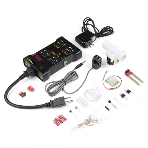
SIK Expansion Kit — Smart Home
KIT-14156
We know that our SparkFun Inventor’s Kit (SIK) line of products helps build a great foundation for building circuits and programming a development board to control those circuits. But, if you want to build your own robot, explore the Internet of Things (IoT) or even track the weather in your backyard, it is a big step to take on your own if your only background in electronics is the SIK, the Arduino 101® SIK or the SparkFun Tinker Kit.
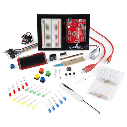
4
Retired
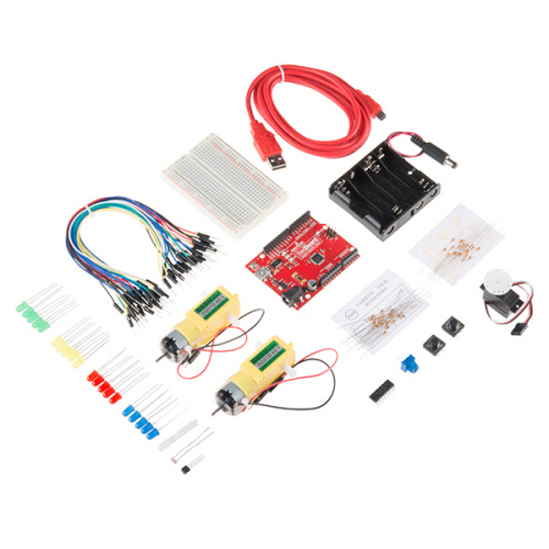
17
Retired
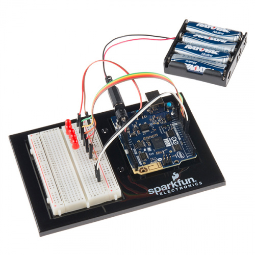
Retired
So, we are developing Expansion Kits that are designed to work with our Inventor’s Kits to help you dive deeper into the concepts, circuits and code required to build more complicated projects with specific themes in mind.
Smart Home…What Is It?
Here at SparkFun we are always hacking our lives to be easier, faster and just plain cooler with the electronics we build and use. Even though we may like to portray the idea that we live and breathe the office, most of us spend a good deal of time at home, so it is just natural for us to hack our homes.
We have packaged the top sensors and actuators that we have used for hacking and modifying our homes into a single kit to make your life easier and more connected. This guide will be your road map to making your house smarter and more in tune with your life.
You probably bought this kit because you have a voice in your head saying, «I really wish I could detect when a door is opened,» or maybe, «How can I tell when my sister has been in my room?» Fear not; this kit will help you answer those questions, but be warned…it will also raise just as many new questions, if not more, which we consider a good thing.
Automation vs. IoT
There is a huge misconception at the moment around home automation. When it comes to a smart home, sometimes the best solution is not always an Internet of Things (IoT) option, especially in terms of security. Sometimes the best solution is not connected to anything at all, but may be the right sensor or actuator for the job used in a creative way.
With that being said, home automation is a great application point for IoT concepts of connectivity, GET requests and interconnected devices. This kit can easily be used with your favorite web-enabled microcontroller to build a number of IoT projects.
This guide, however, will focus on the automation side of things, using the Arduino 101 board and its onboard Bluetooth Low Energy (BLE) capabilities paired with a phone app called Blynk. The focus is on how to make things happen automatically, or at least with minimal control/input from you, to make your life easier, faster and smarter.
A Touch of Blynk
![]()
If you have already gone through the SIK for the Arduino 101 board, you have already dabbled a bit with the onboard BLE aspect of the board. Well, this guide will take a deeper dive into BLE using the Arduino 101 board with a smartphone app called Blynk. A number of experiments leverage Blynk in a way that makes sense to give you remote control or sensing capabilities. We don’t use Blynk in every experiment, but all circuits have the potential to be integrated into a Blynk project on your own. By the end of this guide, you should be well-versed enough in Blynk and the circuits to go back and build your own around the home Blynk projects.
Choose Your Own Adventure!
This guide is specifically written for the Arduino 101 board to leverage the onboard BLE when using Blynk. But if you have a different development board you are using — or an Arduino with a WiFi shield, BLE shield or even just a standard UNO tethered to your laptop — you can still follow along with this guide!
Here are a couple of components that will help you connect your Around-the-Home Kit to Blynk with BLE, WiFi or something else!
BLE
The Arduino 101 board has onboard BLE support for Blynk, but there are a number of other boards and shield that you can connect to Blynk using BLE. Here are a few that we carry, but you can always look up supported hardware on the Blynk website for the most up-to-date hardware list!
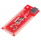
4
Retired
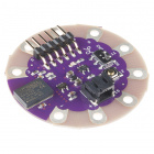
2
Retired
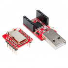
4
Retired
Wired (Ethernet)
Blynk works through an ethernet connection and is as simple as adding an Ethernet shield to your UNO, using a Yun or even a Raspberry Pi or Tessel 2 if you want to go fancy!
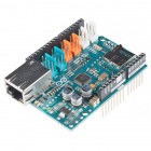
Arduino Ethernet Shield 2
DEV-11166
6
Retired
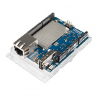
14
Retired
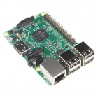
92
Retired
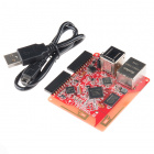
4
Retired
WiFi
The next layer of connectivity with Blynk is using WiFi. This is by far the most flexible way to connect to your project and offers a truly IoT experience, with your project being able to connect to WiFi that it is within range of and you being able to control and monitor your project from anywhere you have cellular data. There are a number of board options, including a Blynk Board, the ESP8266/ESP32 Thing Boards, and the Intel Edison.
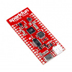
69
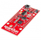
71
22
Retired
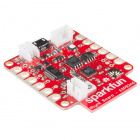
16
Retired
XBee
This has the farthest range of the options above (without going to a cellular development board) but is still tethered to a computer for serial connection. XBee can be used as a USB cable replacement when you are talking to a development board over serial connection. As with the Blynk tethered option, this gives you wireless communication while not having access to a WiFi infrastructure. To explore using XBee with Blynk, check out the kit below and this documentation on using Blynk with an Arduino and no shield.
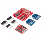
2
Retired
What’s in the Kit?
Included Materials
Here are all of the parts in the Around-the-Home Expansion Kit for the SparkFun Inventor’s Kit for the Arduino 101 board.
- IoT Relay — A device that enables you to control an AC outlet using a GPIO pin
- PIR Motion Sensor — Detects motion using infrared
- BME280 Barometric Pressure/Temperature/Humidity Sensor — An I2C sensor that measures pressure, temperature, humidity and altitude
- Magnetic Door Switch — The magnetic door switches you see in home security systems
- Sealed Reed Switch — A magnetically actuated switch, sealed in plastic rather than the standard glass
- N-Channel MOSFET — N channel MOSFET that is normally open and can control up to 30 volts
- 12V Solenoid Valve — Solenoid valve that has 3/4″ threads on both ends; should fit on a home garden hose with a simple adapter.
- SparkFun Moisture Sensor — Changes resistance based on the moisture level between the two prongs
- Non-Invasive Current Sensor — Sensor that detects the magnetic field generated by current flowing through a wire
- TRRS Breakout — Breakout board for the Tip, Ring, Ring, Sleeve headphones connector
- 10 uF Capacitor — A capacitor that stores and releases energy
- Magnet — Yep…a magnet with a hole in it
- Female Disconnects — Connectors used to connect bare wire to the tabs on the solenoid valve
- Infrared LED — An LED that emits infrared light
- Infrared Detector — Detects the frequency of infrared light that comes in contact with it
Bring Your Own Parts (BYOP)
This kit is designed to expand on the hardware and/or kit you already own. We assume that you have already worked through the SparkFun Inventor’s Kit for the Arduino 101 and have most of the parts that came with that kit including an Arduino 101. We will ask you to put some of those parts to use in this experiment guide from time to time. So, go dust of that old SIK or cardboard box of parts, because you are gonna need ’em!
Experiment List
The following is a list of the experiements you will complete using the Around-the-Home Kit. Alternatively, you can navigate around using the buttons on the right.
- Experiment 1: Hello, World…Again
- Experiment 2: Using a Reed Switch
- Experiment 3: RGB Night Light
- Experiment 4: Reading a Door Switch
- Experiment 5: Motion!
- Experiment 6: Controlling a Solenoid with a MOSFET
- Experiment 7: Reading a Moisture Sensor
- Experiment 8: Atmospheric Conditions with BME280
- Experiment 9: Using a Current Sensor
Suggested Reading
Before continuing with this guide, we recommend you be somewhat familiar with the concepts in the following tutorials:
- Arduino 101 SIK Guide — The step-by-step guide to the SIK for the Arduino 101. Make yourself familiar with this before diving into these experiments.
- Voltage, Current, Resistance and Ohm’s Law — The most basic concepts in electronics and electrical engineering. Get very familiar with these concepts, as they will be used throughout your electronics adventure.
- What Is a Circuit? — In this guide, we will be building a variety of circuits. Understanding what that means is vital to understanding the Inventor’s Kit.
- How to Use a Breadboard — First time working with a breadboard? Please check out this tutorial! It will help you understand why the breadboard is great for prototyping and how to use one.
Open Source!
At SparkFun, our engineers and educators have been improving this kit and coming up with new experiments for a long time. We would like to give attribution to Oomlout, since we originally started working off the Arduino Kit material many years ago. Both the Oomlout and SparkFun versions are licensed under the Creative Commons Attribution Share-Alike 3.0 Unported License.
To view a copy of this license visit this link, or write: Creative Commons, 171 Second Street, Suite 300, San Francisco, CA 94105, USA.
Setting Up Blynk and the Arduino 101 Board
To make sure everything works smoothly and to ensure that your Arduino 101 board works seamlessly with the device you are going to use to control it with we have some specific steps for you to take to properly configure your Arduino IDE.
Arduino 101 Board Definitions and Libraries
Blynk over BLE with the Arduino 101 requires you to install the newest Blynk Arduino library which needs to be installed through downloading it from gitHub. It also requires you to use an older version of the Arduino 101 board definition files. This portion of the guide will walk you through getting your Arduino environment setup.
Board Definition Files
When you installed the Arduino 101 in your Arduino IDE you probably installed the most recent board definition file. Depending on when that was, you may need change that version. To check your board definition version select Tools > Board: > Boards Manager…
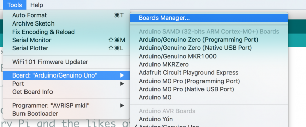
Once you open the boards manager scroll down to your Intel Curie boards and select it. Your board definition file version should be next to the «Intel Curie Boards» title. If the version is higher than 1.0.7 you need to install an older version. To do this use the version drop down menu and select 1.0.7 and click «install». This will change your board definitions.
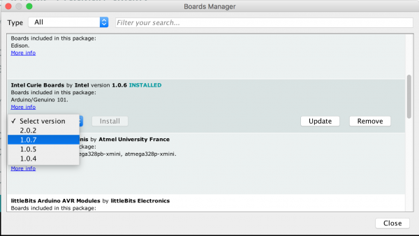
Finally, for these board definition files to take effect restart your computer.
If You Need to Walk Your Board back to 1.0.7
If you have been working with an Arduino 101 board that has the newest firmware on it (2.2.0) you will need to rewrite the bootloader firmware of the board. To do this, be sure that you have installed the 1.0.7 board definitions as shown above. Then connect your Arduino 101 Board to your computer using a USB Cable and in the Arduino IDE set your board to Arduino/Genuino 101 (Tools > Board > Arduino/Genuino 101) and set your correct port (Tools > Port > COM## (Arduino / Genuino 101).
Next, select your programmer by selecting Tools > Programmer > Arduino / Genuino 101 Firmware Updater
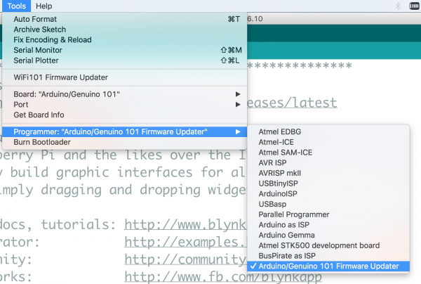
Finally, burn the firmware (bootloader) by selecting Tools > Burn Bootloader
You will see the firmware updater stream by in the Arduino IDE console. If you succeeded in updating / back dating your version to 1.0.7 you should see the following output.
Installing the Blynk Libraries
Yes, the heading is not a typo, blynk is actually multiple libraries to make it easier for you in the long run. But, this requires a bit more leg work on your part at the beginning. You need to download the zip file of the library and install it manually. To do so click the button below to download the most current version of the library.
This should download to your Downloads folder, or wherever you have specified your browser to install.
Next, in Arduino navigate to Sketch > Include Library > Add zip Library…. Point the dialog box at the zipped version of the library you just downloaded and select «choose».
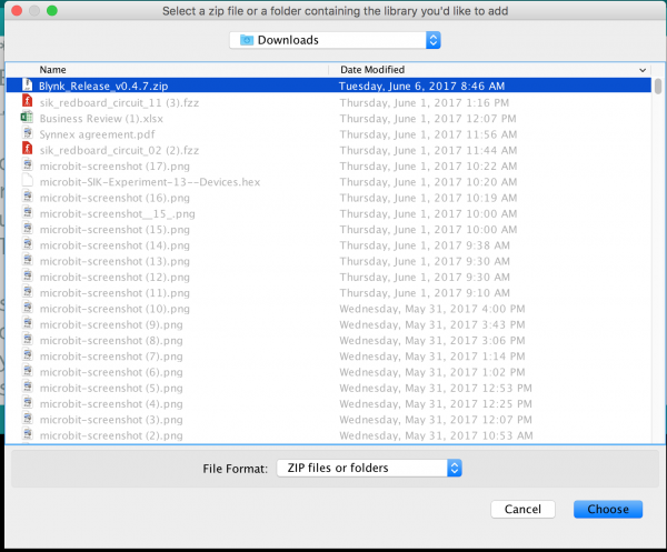
This will unzip and install the library for you. You may need to restart Arduino for the library to be visible in your drop down menus.
With that you are ready to go on the hardware side of things, now to get the Blynk app up and running on your phone!
The Blynk App
The Blynk smartphone app comes in two flavors: iOS and Android. But, BLE is only supported by Andriod devices at this time! Before going any further, download the app to your smart device:
Note: At the time of writing this documentation, BLE communication in Blynk for the Arduino 101 is only supported by Android Devices. There are plans to change this soon!

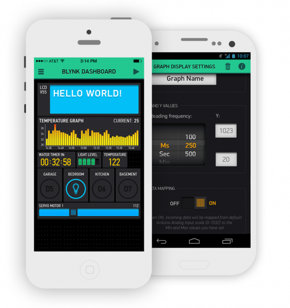
The Blynk app is compatible with Android devices running any version above or equal to 4.0. Blynk was originally designed to control your DIY electronics projects through WiFi. In recent releases Blynk has adopted the ability to control your projects through Bluetooth/BLE, which is exciting for us because that includes support for the Arduino 101!

Once you have installed Blynk on your phone or tablet, you can create a project in your app.
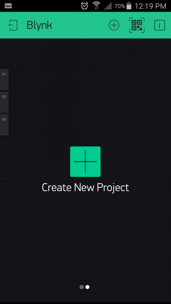
Once you name your project, you can select a board and communication method. In this case you should select Arduino 101 and BLE.
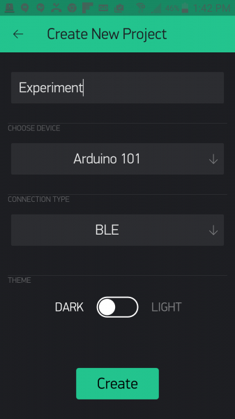
You can then create your app and start to add widgets to it!
Blynk With BLE Has Its Limits
We want to make sure you realize that at this point using Blynk over BLE limits the options of different widgets and tools you can use in your Blynk apps. Once you add the BLE widget to your app, you will notice that other widgets will be grayed out, accompanied by a note about them not being supported yet.
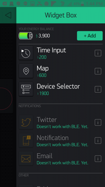
Blynk is well-maintained and updated regularly, so we foresee more and more of these widgets becoming available over time. For now, this documentation uses the widgets that are supported by BLE, and we will update this guide with more experiments as new widgets are supported for use with the Arduino 101 board.
Experiment 1: Hello, World…Again
Introduction
This experiment assumes that you have already gone through the SparkFun Inventor’s Kit for the Arduino 101 Board. If you have not, we recommend at least going through the first few experiments here. But, we realize that it may have been awhile for you, so we are going to make sure that everything is up and running and that you can upload code to your Arduino 101 board. Yep, you guessed it: Hello, World…Again! But this time it’s with a twist. Let’s get blinking!
Parts Needed
You will need the following parts:
- 1x Arduino 101 Board (From your Arduino 101 SIK)
- 1x Breadboard (From your Arduino 101 SIK)
- 1x IoT Relay
- 2x Jumper Wires (From your Arduino 101 SIK)
Didn’t Get the Around-the-Home Expansion Kit?
If you are conducting this experiment and didn’t get the Around-the-Home Expansion Kit, we suggest using these parts:
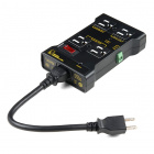
20

2
You will also need an Arduino 101 board.

9
Retired
Suggested Reading
Before continuing with this experiment, we recommend you be familiar with the concepts in the following tutorial:
- Light-Emitting Diodes — Learn more about LEDs
Introducing the IoT Relay
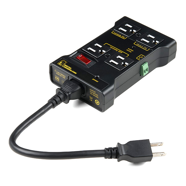
You have turned LEDs on and off, but have you ever wondered how you could use your Arduino 101 to turn bigger things — like lamps, fans and even your refrigerator — on and off? Enter the IoT relay!
The IoT relay looks like a simple power strip you would find around your home, but it has a few tricks up its sleeve. First of all you will notice that the plug receptacles are labeled. One is labeled «Normally On,» and the other is «Normally Off.» This allows you to do a couple of different things. First, you can control whether your GPIO logic from your Arduino is reverse (HIGH = OFF). Or, a little less apparent, is the ability to toggle two different appliances by toggling a GPIO pin. For example, if you plug two lamps in and leave both on, you can toggle which one is on and which one is off by toggling a GPIO pin.
You may ask yourself, «What GPIO pin?» The IoT relay has a screw terminal connection that you supply a signal wire that you can connect to any GPIO pin on your Arduino board, as well as a ground pin connected to the Ground pin on your Arduino. That’s it! You can now control any appliance plugged into your IoT relay with an Arduino.
Hardware Hookup
Ready to start hooking everything up? Check out the wiring diagram below to see how everything is connected.
Wiring Diagram for the Experiment
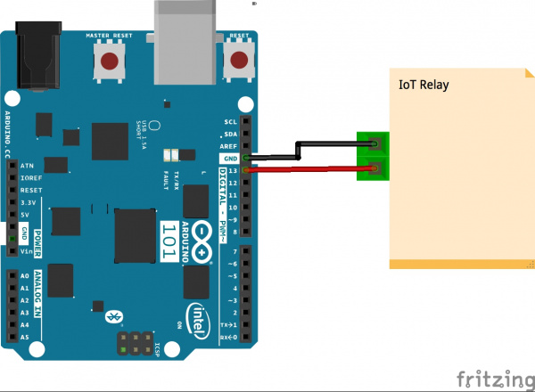
Having a hard time seeing the circuit? Click on the wiring diagram for a closer look.
Build Your Blynk App
The last part of this experiment is to build the app itself. You created it earlier to get an authorization token, but now you need to add widgets to be able to control your Arduino 101 board.
Open your Blynk app and navigate to the blank project that you created for this experiment.
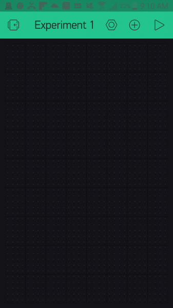
To control the IoT relay, which you have connected to pin 13, you are going to use the button widget in your app. To add the button widget press the (+) logo in the upper right-hand corner of the app. This will bring up a list of widgets as shown below.
Select the Button widget, which will add it to your app. From there you can press and hold to drag the button around your app. Once you have placed it, you can also resize it to fit. We centered ours and made it full width.
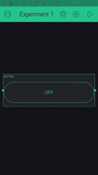
Now to make your button functional! Tapping on the button once will bring up the settings menu for that button. From here you can label the button — we named ours «Lamp.» You then assign the pin that you want it to control — we chose «D13,» or digital pin 13. There are a number of other pins you can use, and we will explore their types in later experiments. Lastly, we selected «switch» as out button functionality so that it stays on or off when we press the button.
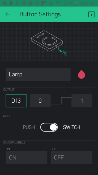
With that you are done with the button! Click the back arrow in the upper left-hand corner.
The last thing we need to do — and something we will have to do with all of our Bynk apps that use the Arduino 101 with BLE — will be to add the BLE widget to our app. Click the (+) button again and scroll down to find the BLE widget
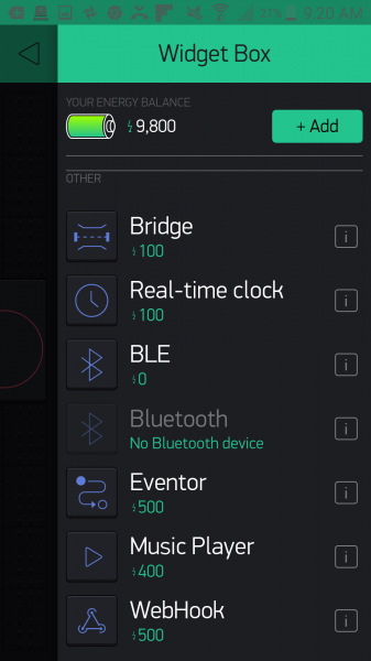
Once you have placed it in your app, go ahead and tap it to open up the BLE settings. You will need to turn Bluetooth and location on in your device for this to work. Click «Connect BLE Device,» and Blynk will search for your Arduino 101 board with the name you gave it in the sketch.
Note: You will also need to turn on your device location setting when connecting to BLE for Blynk as well.
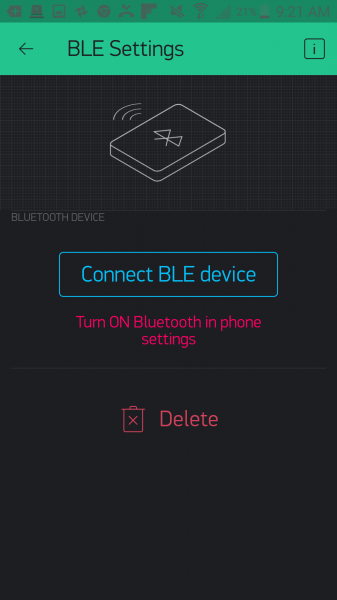
If everything works to plan, your Arduino 101 will show up in a list. Go ahead and select it. Your device will connect to your 101 board, and you should get confirmation of connection in the app.
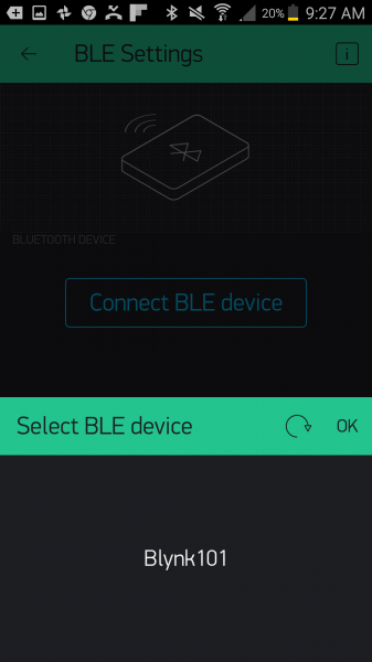
You can now go back to your main app window and run your app by clicking on the play button in the upper right-hand corner. Once the app starts, you can click on the «Lamp» button, and the LED on the Arduino 101 board will turn on and off. But more importantly, whatever you have plugged into your IoT relay will turn on and off!
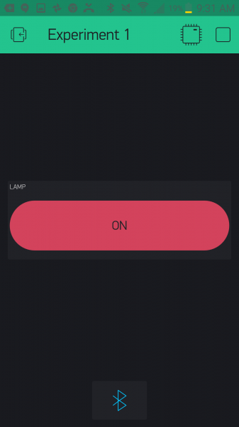
Before you go ahead and launch your app, be sure to upload the sketch to your Arduino 101 board first!
Upload Your First Sketch
Open the Arduino IDE software on your computer. To find this example/basic sketch to control circuits with Blynk in Arduino, navigate to File > Examples > Blynk > Boards_Bluetooth > Arduino_101_BLE
When you created your app in the previous section, an authorization token was automatically emailed to you. Check your inbox and have the token on hand; you will need to add it to your Arduino sketch before you upload it to your Arduino 101 board.
Replace "YourAuthToken" with your token. Make sure you keep it in quotes as a String; otherwise you will get an error when you try to compile your sketch.
You can also type out or copy and paste the following code into the Arduino IDE. Hit upload, and see what happens!
language:cpp
/********************************************************************************
SparkFun Around-The-Home SIK Expansion Kit, Experiment 1
SparkFun Electronics
Product URL

Controls the IoT relay with the Arduino 101 board through the use of the Blynk app.

This example is written by: Derek Runberg, Educational Technologist

This sketch was written by SparkFun Electronics, with lots of help from the Arduino community.
This code is completely free for any use.

View circuit diagram and instructions at:https://learn.sparkfun.com/tutorials/around-the-home-expansion-kit

********************************************************************************/


//#define BLYNK_USE_DIRECT_CONNECT

#define BLYNK_PRINT Serial

#include <BlynkSimpleCurieBLE.h>
#include <CurieBLE.h>

// You should get Auth Token in the Blynk App.
// Go to the Project Settings (nut icon).
char auth[] = "YourAuthToken";

//create a BLE peripheral object
BLEPeripheral  blePeripheral;

void setup() {
 //start the Serial port at 9600 baud
 Serial.begin(9600);
 //wait 1 second
 delay(1000);

 //give your project a local and device name
 blePeripheral.setLocalName("Exp_01");
 blePeripheral.setDeviceName("Exp_01");
 //set the BLE appearance
 blePeripheral.setAppearance(384);

 //start Blynk
 Blynk.begin(blePeripheral, auth);

 //start the BLE service
 blePeripheral.begin();

 Serial.println("Waiting for connections...");
}

void loop() {
 Blynk.run();
 blePeripheral.poll();
}
Code to Note
The basic blocks of this sketch focus on enabling the Bluetooth on your Arduino 101 board and setting up and running the Blynk firmware. This is the basic example sketch for using the Arduino 101 and BLE with Blynk, and throughout this experiment guide we will be using this as the foundation for other Blynk-based sketches to come. For the sake of reference, here are a few commands that you should have a solid understanding of for use with the experiments:
#define BLYNK_PRINT Serial
This define statement points the Blynk debug console to the Serial port on the Arduino 101. To see this feedback information, hook your Arduino 101 up to your computer using your USB cable and open your Serial monitor. You can all turn this off by commenting this statement out using // in front of the statement. This will help to speed up your sketch and save room.
char auth[] = "YourAuthToken";
When you build a Blynk app, it is assigned an authorization token that gets emailed to the email account attached to the Blynk app. To make sure your Arduino 101 board talks to your app and only your app, you need to replace «YourAuthToken» with your token inside quotes.
language:cpp
blePeripheral.setLocalName("Exp_01");
blePeripheral.setDeviceName("Exp_01");
These commands enable you to give your Arduino 101 board a name that it broadcasts to all BLE-enabled devices around it. As a default throughout this guide we will be using the experiment number, for this experiment it is named «Exp_01», but you can change it to whatever string you would like. We recommend changing both the local name and device name to the same name.
language:cpp
 Blynk.begin(blePeripheral, auth);
 blePeripheral.begin();
On the Arduino 101 board you need to start Blynk first and pass it the blePeripheral object and your authorization token. You then can start the BLE service on your Arduino 101 board.
language:cpp
void loop() {
 Blynk.run();
 blePeripheral.poll();
}
After all of that setup, the loop of this sketch is almost comically short. It contains two methods. The first one runs Blynk, which polls the app on your device and makes sure that it is in sync with what’s happening on your board.
The second method does a similar action, but manages your BLE connection between the Arduino 101 and your phone or tablet.
That’s it! Like we said, this is the foundation we will be using and adding to over the course of the next eight experiments.
What You Should See

Your lamp that you plugged in to the IoT Relay’s «Normally On» plug should turn on and off when you press the button in your Blynk app! Try different appliances or add another lamp to the «Normally Off» plug and use the button to switch between the two different lamps.
[INSERT VIDEO OF FUNCTIONALITY]
Troubleshooting
Blynk Shortcut!
If you are having troubles duplicating the functionality above in the Blynk app, scan this QR code with Blynk to get a clone of this experiment!

Program Not Uploading
This happens sometimes; the most likely cause is a confused serial port. You can change this in Tools > Serial Port >
Also, if you get a Timeout error or the IDE could not find your 101 board, try pressing the Master Reset button on the 101, wait about 10 seconds and try re-uploading your sketch.
Still No Success
A broken circuit is no fun. Send us an email, and we will get back to you as soon as we can: techsupport@sparkfun.com
Experiment 2: Using a Reed Switch
Introduction
Detecting the presence of an object is always tough. If you base it off of weight, you always run the risk of someone placing something on your sensor or even just leaning on it. Then there are other, more complicated means that can also produce false positives or negatives.
Enter the reed switch! A reed switch is a simple switch that is triggered by a magnet, so unless you have a lot of magnets sitting around, it gives you an easy way to detect a specific object by simply adding a magnet to it. You can then place the reed switch circuit under a table, under a bowl or plate or even under a drawer to detect if the drawer is opened or closed if you have a powerful enough magnet.
This experiment will build on Experiment 1 where you controlled the IoT Relay with a button in Blynk. You will build an app in Blynk that will help you find your keys by having an indicator LED in the Blynk app turn on if your keys are in a bowl strategically placed by your front door!
Parts Needed
You will need the following parts:
- 1x Breadboard (From your Arduino 101 SIK)
- 1x Arduino 101 Board (From your Arduino 101 SIK)
- 1x Reed Switch
- 2x Jumper Wires (From your Arduino 101 SIK)
- 1x 10k Ohm Resistor (From your Arduino 101 SIK)
- 1x Magnet Ring — 3/16″
Didn’t Get the Around-the-Home Expansion Kit?
If you are conducting this experiment and didn’t get the Around-the-Home Expansion Kit, we suggest using these parts:
You will also need an Arduino 101 board.
9
Retired
Suggested Reading
Before continuing with this experiment, we recommend you be familiar with the concepts in the following tutorials:
- Light-Emitting Diodes — Learn more about LEDs
- Switch Basics — Learn more about buttons and switches
- Reed Switch Hookup Guide
Introducing the Reed Switch
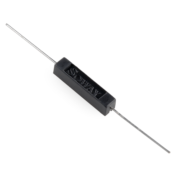
Reed switches are magnetically actuated electrical switches (not magically actuated, though it seems that way sometimes). When the body of the switch is exposed to a magnetic field — like a magnet or even a strong electrical current — two ferrous materials inside pull together, the connection closes, and current can flow. In the absence of a magnetic field, the switch opens, as does the circuit it’s a part of.
There are all sorts of creative applications for reed switches. They’re perfect for any projects that require non-contact control. A magnetic door switch, for example, is just a dressed-up reed switch and a mating magnet. By keeping both parts of the switch separate, the door can open and close freely (and maintain its regular duties as a door). The anemometer in our weather meter combines a number of reed switches, which all open and close in order as the wind blows; count the time between switch closures to determine the wind speed.
Here is a quick demonstration of a simple circuit that uses a reed switch to control an LED circuit.
Note: Your reed switch will look a little different from the one in the video because it is sealed in plastic rather than a glass enclosure.
Hardware Hookup
Ready to start hooking everything up? Check out the wiring diagram below to see how everything is connected.
Wiring Diagram for the Experiment
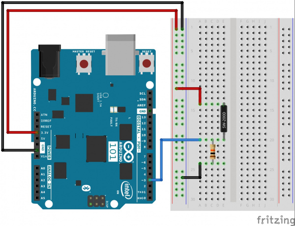
Having a hard time seeing the circuit? Click on the wiring diagram for a closer look.
Build Your Blynk App
Start out by building a fresh app in Blynk. Again, your authorization token will be emailed to you; make sure you add it to your Arduino sketch before uploading it!
In this new app add an LED widget by clicking the (+) sign in the upper right-hand corner and find the LED widget from the list.
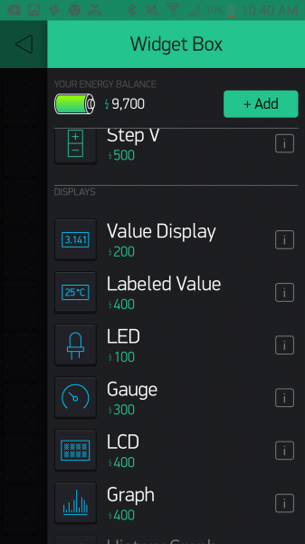
Once you select it and place the widget, open up the settings by pressing once on the widget. Here you can name it as in the previous experiment, and if you want to change the color, you can do so by clicking the teardrop logo next to the name. Finally, set the pin to virtual pin 3 or V3. Notice that the LED widget only accepts virtual pin numbers, which means that if you want to use this widget you need to follow this experiment’s example of turning the widget on and off from your Arduino 101 board.
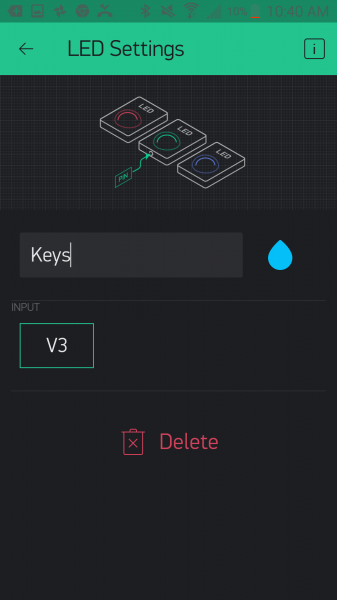
From there you add the BLE widget, as you did in Experiment 1. Be sure to have BLE and location turned on to be able to set up and connect to your Arduino 101 board. From there you should be good to go!
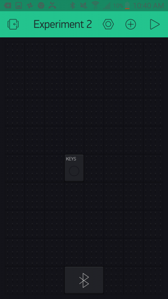
Upload Your Sketch
You will be adding to the example Arduino 101 BLE sketch we used in Experiment 1. Feel free to open that in Arduino by navigating to File > Examples > Blynk > Bluetooth >Arduino_101_BLE or copy and paste the code below.
Make sure you add the authorization key from your Blynk app; otherwise this sketch will not work!
language:cpp
/********************************************************************************
SparkFun Around-The-Home SIK Expansion Kit, Experiment w
SparkFun Electronics
Product URL

Detects the presence of an object attached to a magnet with a reed switch. If a magnet is present it turns on an LED widget in a Blynk app.

This example is written by: Derek Runberg, Educational Technologist

This sketch was written by SparkFun Electronics, with lots of help from the Arduino community.

This code is completely free for any use.

View circuit diagram and instructions at:https://learn.sparkfun.com/tutorials/around-the-home-expansion-kit

********************************************************************************/

/* Comment this out to disable prints and save space */
#define BLYNK_PRINT Serial

#include <BlynkSimpleCurieBLE.h>
#include <CurieBLE.h>


// You should get Auth Token in the Blynk App.
// Go to the Project Settings (nut icon).
char auth[] = "YOUR_AUTH_TOKEN";

// Select your pin with physical button
const int REED_SWITCH = 3;

WidgetLED led3(V3);

BlynkTimer timer;
BLEPeripheral  blePeripheral;

// V3 LED Widget represents the physical button state
boolean reedState = false;
//LED on pin 13
const int LED_PIN = 13;

void setup()
{
  // Debug console
  Serial.begin(9600);

  //give your project a local and device name
 blePeripheral.setLocalName("Exp_02");
 blePeripheral.setDeviceName("Exp_02");
 //set the BLE appearance
 blePeripheral.setAppearance(384);

 //start Blynk
 Blynk.begin(blePeripheral, auth);

 //start the BLE service
 blePeripheral.begin();
  // Setup physical button pin (active low)
  pinMode(REED_SWITCH, INPUT);
  //set LED_PIN as output
  pinMode(LED_PIN,OUTPUT);

  timer.setInterval(100L, checkState);
}

void loop()
{
  Blynk.run();
  blePeripheral.poll();
  timer.run();
}

void checkState()
{
  // Read switch
  boolean isPressed = (digitalRead(REED_SWITCH) == HIGH);

  // If state has changed...
  if (isPressed != reedState) {
    if (isPressed == HIGH) {
      led3.on();
      digitalWrite(LED_PIN,HIGH);
    } else {
      led3.off();
      digitalWrite(LED_PIN,LOW);
    }
    reedState = isPressed;
  }
}
Code to Note
In this example we read the reed switch and, depending on its state, we turn the LED widget in the app on or off.
BlynkTimer timer;
The lessons learned here are that you can create a widget object in your Arduino sketch and control it via code. Also, the idea of a timer is important here. If we placed all of our code into the loop() Arduino and Blynk would throw overflow errors. We can only send so much data to our Blynk app before it gets overwhelmed. So, we use the BlynkTimer object to set a time interval for a custom function — in this case, check the state of the reed switch and toggle the LedWidget depending on that value.
const int REEDSWITCH = 3;
In this sketch we store the pin number that the reed switch is connected to as a global constant integer. We do this so we can easily change the pin number in one place at the top of the sketch, but also so the pin number cannot be changed in code for any reason. This is safe programming practice that we will employ throughout this set of experiments.
WidgetLED led(V3);
The Blynk library for Arduino doesn’t use the conventional setup and use for pins using the Arduino language. Instead, it uses object notation! So, to create an LED widget you define an object of WidgetLED (we called ours «led») and then pass it the virtual Blynk pin that you would like to assign to it — in this case v3, or virtual pin 3.
boolean isPressed = (digitalRead(REED_SWITCH) == LOW);
Inside of the custom function we create a local Boolean variable called isPressed and store the state we get from the logical statement on the reed switch. If a magnet is present, this value will be true; if it is absent, the value will be false.
language:cpp
  // If state has changed...
  if (isPressed != reedState) {
    if (isPressed == true) {
      led3.on();
    } else {
      led3.off();
    }
    reedState = isPressed;
  }
We finally use an if() statement to control the LED widget. If the isPressed variable is equal to true the LED widget will turn on. If the state variable is false the widget will be off.
Notice that there is a bit of a delay between removing the magnet and the LED widget toggling. This is due to a bit of latency built up between the BLE polling and the timer. In this application this works because we are looking for the presence of something that doesn’t move that often.
What You Should See
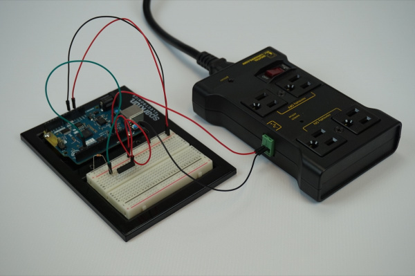
When you hold a magnet close to the reed switch, the LED on connected to pin 13 on the Arduino 101 should turn on, and the LED widget in your app should also turn on. When the magnet is removed, the LED and the widget indicator should turn off.
Note: We have observed that there may be a delay of up to 7 seconds between you adding or removing the magnet and the LED widget on your phone. This is normal and should update with maturity of the Blynk BLE API.
[INSERT VIDEO]
A great application for this circuit would be to find a bowl for your keys and insert this circuit in the base. Hook up the IoT Relay to pin 13 on the Arduino 101 as shown in Experiment 1. Then, place the magnet on your key chain. When you get home late at night, all you need to do is throw your keys into your newly built bowl, and a lamp plugged into the IoT Relay will turn on. When you are in a rush to leave and can’t find your keys, you can check to see if they are where they should be or not. When you take the keys from the bowl, the lamp turns off as you leave.
The great thing about this small experiment is that it highlights that not everything has to be connected to Blynk or Arduino in order for the two functions to work. You can use Blynk or not, and it doesn’t get in the way of the Arduino sketch!
This experiment may seem overly simple, but it is here as something for you to build off of. Add other sensors and LED widgets to create indicators for different states of a project. Blynk has almost infinite virtual pins, so you are limited only by the number of LED widgets you can fit on your screen!
Troubleshooting
Blynk Shortcut!
If you are having troubles duplicating the functionality above in the Blynk app, scan this QR code with Blynk to get a clone of this experiment!

Program Not Uploading
This happens sometimes; the most likely cause is a confused serial port. You can change this in Tools > Serial Port > and make sure you are using an Arduino 101 board.
Not Connecting to the Blynk App
Be sure to check that your Bluetooth is on. Also make sure your authorization token is correct and in your sketch!
Still No Success
A broken circuit is no fun. Send us an email, and we will get back to you as soon as we can: techsupport@sparkfun.com
Experiment 3: RGB Night Light
Introduction
OK, your mind has been blown by your newly found superpowers of using the Blynk app with the Arduino 101 board. Before moving on to new parts and concepts to get creative with, we want to highlight something for you: the idea that you have an entire Inventor’s Kit for the Arduino 101 board at your disposal in terms of other parts to use and leverage.
In this experiment we will build on your previous experience with the SIK for the Arduino 101 board and the hardware that came with it to highlight that, by adding Blynk to the equation, you have quite the toolkit available to you in terms of parts to use to build interconnected devices and projects.
We are going to take the night-light circuit you built in Experiment 3 from the Arduino 101 SIK Experiment Guide and modify it into a project that uses Blynk to make it more interactive through the use of an RGB LED that you will be able to control the color of. With this custom-colored night light, your bathroom ambiance will never be the same!
Parts Needed
You will need the following parts:
- 1x Breadboard (From your Arduino 101 SIK)
- 1x Arduino 101 Board (From your Arduino 101 SIK)
- 1x Light Sensor (From your Arduino 101 SIK)
- 1x 10k Ohm Resistor (From your Arduino 101 SIK)
- 1x RGB LED Clear Common Cathode (From your Arduino 101 SIK)
- 3x 100 Ohm Resistors (From your Arduino 101 SIK)
- 9x Jumper Wires (From your Arduino 101 SIK)
Didn’t Get the Around-the-Home Expansion Kit?
If you are conducting this experiment and didn’t get the Around-the-Home Expansion Kit, we suggest using these parts:
You will also need an Arduino 101 board.
9
Retired
Suggested Reading
Before continuing with this experiment, we recommend you be familiar with the concepts in the following tutorials:
- Light-Emitting Diodes — Learn more about LEDs
- Switch Basics — Learn more about buttons and switches
- Reed Switch Hookup Guide
Introducing the Red Green Blue (RGB) LED
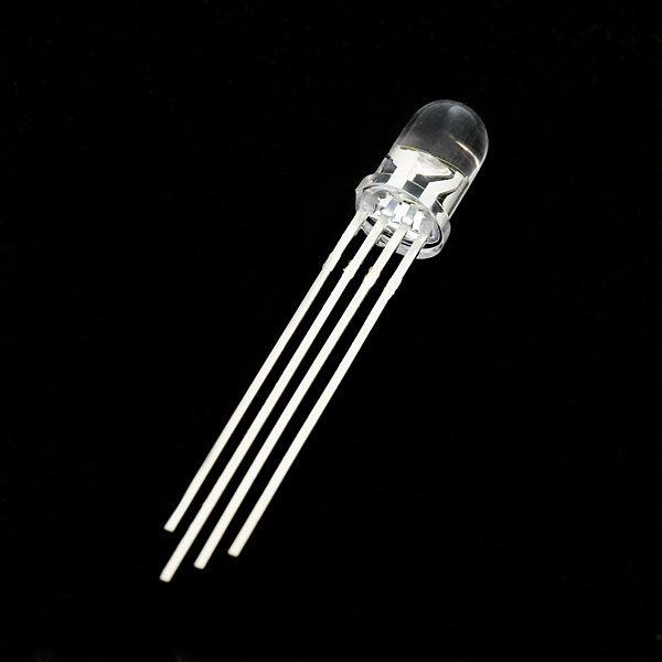
We know that the RGB is probably nothing new to you at this point, but we wanted to give you a bit of a refresher course if it has been awhile.
The Red Green Blue (RGB) LED is three LEDs in one. The RGB has four pins with each of the three shorter pins controlling an individual color: red, green or blue. The longer pin of the RGB is the common ground pin. You can create a custom-colored LED by turning different colors on and off to combine them. For example, if you turn on the red pin and green pin, the RGB will light up as yellow.
But which pin is which color? Pick up the RGB so that the longest pin (common ground) is aligned to the left as shown in the graphic below. The pins are Red, Ground, Green and Blue — starting from the far left.
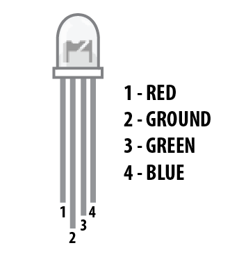
**Note: When wiring the RGB, each colored pin still needs a current-limiting resistor in line with the 101 pin that you plan to use to control it, as with any standard LED. **
Hardware Hookup
Ready to start hooking everything up? Check out the wiring diagram below to see how everything is connected.
Wiring Diagram for the Experiment
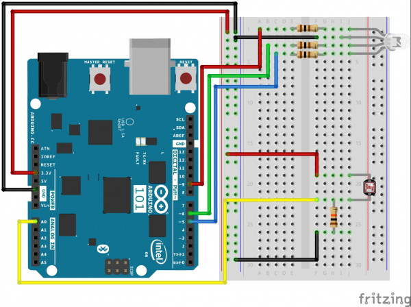
Having a hard time seeing the circuit? Click on the wiring diagram for a closer look.
Build Your Blynk App
Start out by building a fresh app in Blynk. Again, your authorization token will be emailed to you; make sure you add it to your Arduino sketch before uploading it!
In this new app, add a zeRGBa widget by clicking the (+) sign in the upper right-hand corner and find the zeRGBa widget from the list.
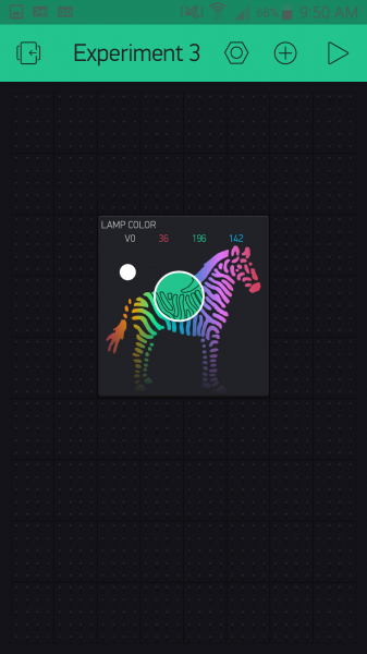
Once you select it and place the widget, open up the settings by pressing once on the widget. Here you can name it like the previous experiment. Finally, set the pin to virtual pin 0 or V0. The zeRGBa widget also has two ways to control pins. You can directly control the pins by using the Split setting and assign each color a pin.
Note: If you have never used an array before, think of it as a list of numbers that are indexed. Here is an example of an array of RGB values for red: [255,0,0], with red being the first number or index 0, green being index 1, and blue being index 2. If you follow this logic, purple would be [255,0,255]. An array can be any length you want!
If you are looking to play around with just an RGB and Blynk, this is a fun option to explore later. We want to use the Merge option, which merges the 3 RGB values into an array of values.
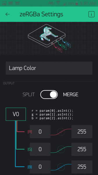
From there you add the BLE widget, as you did in Experiment 1. Be sure to have BLE and location turned on to be able to set up and connect to your Arduino 101 board. From there you should be good to go!
Upload Your Sketch
Copy and paste or type out the code below.
Make sure that you add the authorization key from your Blynk app; otherwise this sketch will not work!
language:cpp
/********************************************************************************
SparkFun Around-The-Home SIK Expansion Kit, Experiment 3
SparkFun Electronics
Product URL

Build an RGB night light where you use the Blynk App to configure the color of the RGB when it is lit.

This example is written by: Derek Runberg, Educational Technologist

This sketch was written by SparkFun Electronics, with lots of help from the Arduino community.
This code is completely free for any use.

View circuit diagram and instructions at:https://learn.sparkfun.com/tutorials/around-the-home-expansion-kit

********************************************************************************/

//#define BLYNK_USE_DIRECT_CONNECT

/* Comment this out to disable prints and save space */
#define BLYNK_PRINT Serial


#include <BlynkSimpleCurieBLE.h>
#include <CurieBLE.h>

// You should get Auth Token in the Blynk App.
// Go to the Project Settings (nut icon).
char auth[] = "YOUR AUTH TOKEN";

BLEPeripheral  blePeripheral;

//RGB pin constants
const int RED_PIN = 9;
const int GREEN_PIN = 6;
const int BLUE_PIN = 5;

//sensor pin constant set at A0
const int SENSOR_PIN = A0;

//preset color of the RGB... Red!
int r = 255;
int g = 0;
int b = 0;
int calibrationVal;

void setup()
{
  // Debug console
 Serial.begin(9600);

 delay(1000);

 blePeripheral.setLocalName("Exp_03");
 blePeripheral.setDeviceName("Exp_03");
 blePeripheral.setAppearance(384);

 Blynk.begin(blePeripheral, auth);

 blePeripheral.begin();

 Serial.println("Waiting for connections...");
 calibrationVal = analogRead(SENSOR_PIN);
}

void loop()
{
  int lightVal = analogRead(SENSOR_PIN);
  //if lightVal is less than the calibration value - 50 (it's dark)...
  if (lightVal < calibrationVal - 50) {
    //display set color
    analogWrite(RED_PIN, r);
    analogWrite(GREEN_PIN, g);
    analogWrite(BLUE_PIN, b);
   }
  else {
    //RGB is off
    analogWrite(RED_PIN, 0);
    analogWrite(GREEN_PIN, 0);
    analogWrite(BLUE_PIN, 0);
  }

  blePeripheral.poll();
  Blynk.run();
}

// zeRGBa assigned to V0
BLYNK_WRITE(V0)
{
  // get a RED channel value
  r = param[0].asInt();
  // get a GREEN channel value
  g = param[1].asInt();
  // get a BLUE channel value
  b = param[2].asInt();
}
Code to Note
In this sketch a lot should look pretty familiar to you. We covered the idea of building a light sensor-based night light in the SIK for Arduino 101 Experiment Guide if you would like to see where we started from here.
In this experiment we use the RGB LED instead of a single LED, which should also be somewhat familiar to you. The focus of this experiment is how we set the color and interact with the RGB through Blynk. Here are a few pieces of code that highlight the Blynk functionality.
char auth[] = "YOUR AUTH TOKEN";
We miss this all the time, so you probably do as well. We want to make sure that you are using your authorization token when you upload the sketch, and not just hitting upload. Be sure to change this string to the token Blynk emails to you.
language:cpp
 //preset color of the RGB... Red!
int r = 255;
int g = 0;
int b = 0;
Part of what we are demonstrating with this sketch is making sure that there is enough information in the Arduino sketch for it to function without any input from Blynk from the beginning. With that in mind, we pre-set the RGB color to an intense red (go figure!). The RGB will then stay red until someone connects to the Arduino 101 with Blynk and changes the color. Since these variables are global, when you change the color with the Blynk app, the color will stay the same even when you disconnect the app from the Arduino 101 board.
language:cpp
 // zeRGBa assigned to V0
BLYNK_WRITE(V0)
{
  // get a RED channel value
  r = param[0].asInt();
  // get a GREEN channel value
  g = param[1].asInt();
  // get a BLUE channel value
  b = param[2].asInt();
}
The Blynk API uses event functions. As it polls your Blynk app for changes using the blynk.run() method, it triggers this event function called BLYNK_WRITE(V0) when data is written to virtual pin 0 in Blynk. When you change your zeRGBa widget, it writes an array of values with a red value being the first, a green value the second, and a blue the last. We parse that array of values within the event function and set the global color variables to the appropriate value. We will use this concept later in other experiments as well, so we wanted to be sure to highlight it in detail now.
What You Should See
Now, plug your project in where you would like a night light. At first nothing will happen. Turn the lights in the room off or cover the light sensor. The RGB should turn on with a red color. Now connect to your Arduino 101 board with Blynk and use the zeRGBa to change the color of your RGB.
Now if you turn the lights on, the RGB will turn off. Turn your lights back off, and the RGB should turn back on with the color you picked earlier. As long as you don’t unplug the Arduino 101 board, the RGB will stay this color whether you use the Blynk app or not. To change the color, use Blynk!
[INSERT VIDEO]
This experiment may seem a bit simple, but it is here to inspire you to incorporate the parts you already have in your SIK for the Arduino 101 board, as well as to think creatively about how to use Blynk and BLE where it makes sense.
Troubleshooting
Blynk Shortcut!
If you are having troubles duplicating the functionality above in the Blynk app, scan this QR code with Blynk to get a clone of this experiment!

Program Not Uploading
This happens sometimes; the most likely cause is a confused serial port. You can change this in Tools > Serial Port > and make sure you are using an Arduino 101 board.
Not connecting to the Blynk App
Be sure to check that your Bluetooth is on as well as your location setting. Also make sure your authorization token is correct and in your sketch!
RGB shows wrong colors
Double check your wiring, you may have the wrong color controlled by the wrong pin on the Arduino 101
Experiment 4: Reading a Door Switch
Introduction
In Experiment 2 you learned how to use a simple reed switch with Blynk and Arduino. In this experiment you will take this a step further and into the world of home security with the magnetic door switch. We will be using Blynk and the Arduino 101 board to arm and disarm your burglar alarm…so watch out, burglars!
Parts Needed
You will need the following parts:
- 1x Breadboard
- 1x Arduino 101 Board
- 1x Magnetic Door Switch
- 1x Buzzer
- 6x Jumper Wires
Didn’t Get the Around-the-Home Expansion Kit?
If you are conducting this experiment and didn’t get the Around-the-Home Expansion Kit, we suggest using these parts:
You will also need an Arduino 101 board.
9
Retired
Suggested Reading
Before continuing with this experiment, we recommend you be familiar with the concepts in the following tutorials:
- Light-Emitting Diodes — Learn more about LEDs
- Switch Basics — Learn more about buttons and switches
Introducing the Magnetic Door Switch
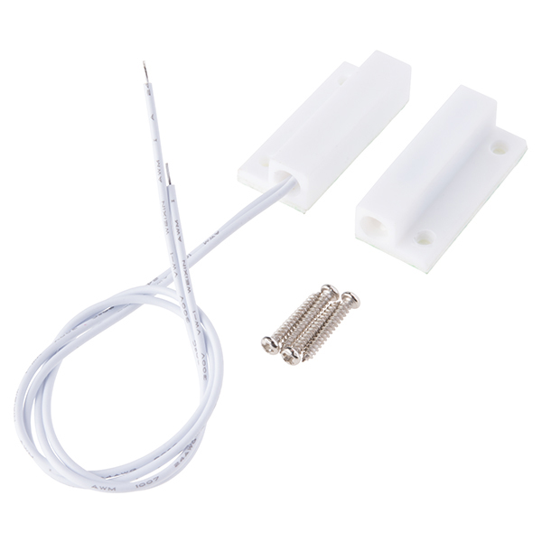
In Experiment 2 you built a circuit containing a reed switch controlled by direct magnet contact: someone placing a magnet on top of the sensor. The door switch included in this kit is roughly the same, but with a specific application in mind as well as wiring added to it so that you can place the sensor a little further away.
The switch assembly has two pieces. When the two halves of the switch assembly are very near each other, or touching, the switch is in one state. Moving the two halves more than 20mm apart from each other will cause the switch to change state. One half contains a magnet, and the other contains a reed switch, a switch that changes state when exposed to a magnetic field.
This type of two-piece switch is often used in home-security systems. One half of the switch is attached to a fixed surface, and the other half to a moving door or window. When the door or window is opened, the two halves are separated from each other, breaking the contact and changing the switch’s state.
Here is a bit of a throwback video description of the door sensor and what it includes for your nostalgic record.
Hardware Hookup
Ready to start hooking everything up? Check out the wiring diagram below to see how everything is connected.
Wiring Diagram for the Experiment
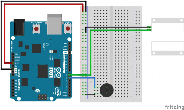
Having a hard time seeing the circuit? Click on the wiring diagram for a closer look.
Build Your Blynk App
Your Blynk app will be your way to arm, disarm, silence and check to see if someone has entered through the door and maybe figured out how to disable the buzzer in some way.
The app consists of two button widgets and an LED widget. One button will control the arming and disarming of the system; the other will be a silencing button to turn the alarm on and off. Finally the LED will be a silent alarm where you can open the app and check to see if someone has entered or not; it will blink if the alarm has been tripped.
To start out, create a new Blynk app and add the BLE widget. Be sure to turn BLE and location on so your phone can connect to the Arduino 101 board using BLE.
Start out by adding a button. We named it «Alarm» and put it into switch mode. The on and off values are «Armed» and «Disarmed.» The pin that the button is connected to is virtual pin 0 or V0.
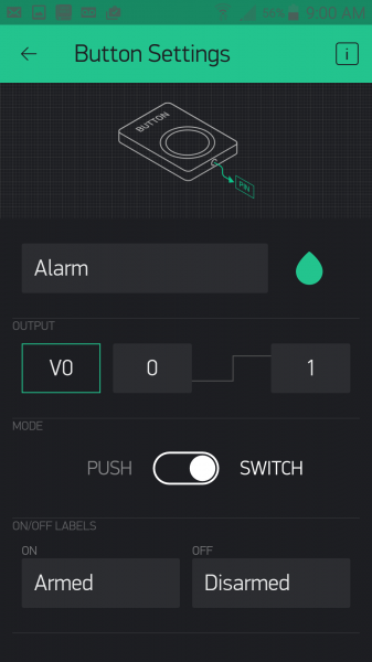
Add another button. This one we named «Silence,» which is connected to virtual pin 1 or V1 and also in «switch» mode. We left the on/off labels as they were.
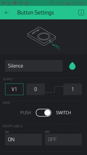
With that, your app should look something like this, maybe with a difference in placement and button colors.
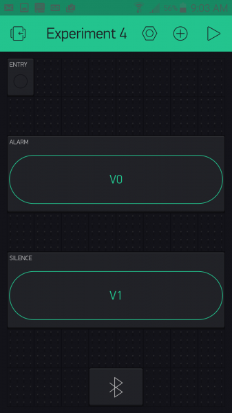
Now, it’s time to add the magic on the Arduino 101 end and complete your security system!
Upload Your Sketch
Let’s get this code knocked out! Be sure to insert your authorization token into your sketch before you upload it; otherwise your app will not work with this code!
You can type out or copy and paste the following code into the Arduino IDE. Hit upload, and see what happens!
language:cpp
/********************************************************************************
SparkFun Around-The-Home SIK Expansion Kit, Experiment 4
SparkFun Electronics
Product URL

Builds a Blynk app controlled door burglar alarm where you can disarm / arm and mute the alarm from a Blynk app that reads a door switch.

This example is written by: Derek Runberg, Educational Technologist

This sketch was written by SparkFun Electronics, with lots of help from the Arduino community.
This code is completely free for any use.

View circuit diagram and instructions at:https://learn.sparkfun.com/tutorials/around-the-home-expansion-kit

********************************************************************************/

/* Comment this out to disable prints and save space */
#define BLYNK_PRINT Serial
#include <BlynkSimpleCurieBLE.h>
#include <CurieBLE.h>

BLEPeripheral  blePeripheral;


// You should get Auth Token in the Blynk App.
// Go to the Project Settings (nut icon).
char auth[] = "your auth token";

//create global constant for component pins
const int SENSOR_PIN = 7;
const int BUZZER_PIN = 6;

//create boolean variables for mute and armed options
boolean mute = false;
boolean armed = false;


void setup()
{
  Serial.begin(9600);
  blePeripheral.setLocalName("Exp_04");
  blePeripheral.setDeviceName("Exp_04");
  blePeripheral.setAppearance(384);

  Blynk.begin(blePeripheral, auth);

  blePeripheral.begin();

  //set BUZZER_PIN as OUTPUT for the buzzer
  pinMode(BUZZER_PIN, OUTPUT);
  //set SENSOR_PIN as INPUT_PULLUP for the door switch
  pinMode(SENSOR_PIN,INPUT_PULLUP);
}

void loop()
{
  int doorState = digitalRead(SENSOR_PIN);
  if(armed == true && doorState == 1){
    if(mute == true){
       noTone(BUZZER_PIN);
    }else{
      tone(BUZZER_PIN, 5000);
    }
  }
  else{
    noTone(BUZZER_PIN);
  }
  Blynk.run();
  blePeripheral.poll();
}

BLYNK_WRITE(V0)
{
  armed = !armed;
}

BLYNK_WRITE(V1)
{
  mute = !mute;
}
Code to Note
pinMode(SENSOR_PIN,INPUT_PULLUP);
To keep the wiring simple and not use a pullup resistor we used the INPUT_PULLUP constant as the pinMode. This internally pulls the pin high and removes the need for the resistor, but then causes the boolean logic of the door switch being open vs. closed.
language:cpp
BLYNK_WRITE(V0)
{
  armed = !armed;
}

BLYNK_WRITE(V1)
{
  mute = !mute;
}
We use two Blynk event functions that are connected to the app via the arm / disarm button and the mute button. We use those events to do nothing but toggle global variables of mute and armed. That way you can arm / disarm and mute the alarm system then disconnect the app and the system will function on its own and not rely on the connection of the app for any real time control.
int doorState = digitalRead(SENSOR_PIN);
We store the state of the door (opened = 1, closed=0) in a local variable called doorState using a simple digitalRead() function.
language:cpp
if(armed == true && doorState == 1){
    if(mute == true){
       noTone(BUZZER_PIN);
    }else{
      tone(BUZZER_PIN, 5000);
    }
  }
We use nested if statements to check the state of the door. If it is close and muted the buzzer is quiet. Else the buzzer sounds using the tone() command at 5000 Hz!
What You Should See
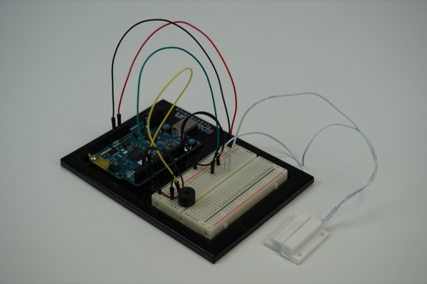
You should power up the circuit with the door switch mounted to the door, or whatever you are securing (cabinet, box, etc.). Make sure the door is closed and connect to your project through Blynk. When you open the app and run it, you should be able to arm the alarm and also set whether the alarm is silent or not. Leave it off for testing. Now, open the door. The alarm should go off, and the LED in your Blynk app should be blinking! You should be able to silence it from the Blynk app, as well as disarm the lock.
The great thing about this system is that when you manipulate the settings using the Blynk widgets your options are saved as variables on the Arduino 101 board, so you should be able to set the alarm and walk away.
[INSERT VIDEO]
Troubleshooting
Blynk Shortcut
If you are having troubles duplicating the functionality above in the Blynk app, scan this QR code with Blynk to get a clone of this experiment!

Buzzer not buzzing
Double check your wiring to the buzzer. It is a polarized port and you may have it backwards, or the wires in your breadboard may not be aligned correctly.
Cannot toggle armed vs. disarmed
Make sure you are connected via BLE to your project and it shows up in your app. The Blynk app is the only way to disarm or mute the alarm system.
Experiment 5: Motion!
Introduction
OK, so you have detected the presence of an object, built a door security system, but what about detecting motion, the number one way we detect people? Enter the PIR (Passive Infrared) motion sensor! In this experiment you will look at how to use the PIR motion sensor to detect, well…motion. We will then put it to an interesting use other than to see whether something is moving or not.
The application of this sensor will be to build a pretty cool and colorful locking/latching system for a cabinet using the PIR motion sensor and an RGB with a servo from your Arduino 101 SIK with Blynk. Ready to go nuts? Yeah, we thought so!
Parts Needed
You will need the following parts:
- 1x Breadboard (From your Arduino 101 SIK)
- 1x Arduino 101 Board (From your Arduino 101 SIK)
- 1x PIR Motion Sensor
- 1x RGB LED Clear Common Cathode (From your Arduino 101 SIK)
- 3x 100 Ohm Resistor (From your Arduino 101 SIK)
- 14x Jumper Wires (From your Arduino 101 SIK)
- 1x Servo Motor (From your Arduino 101 SIK)
Didn’t Get the Around-the-Home Expansion Kit?
If you are conducting this experiment and didn’t get the Around-the-Home Expansion Kit, we suggest using these parts:
You will also need an Arduino 101 board.
9
Retired
Suggested Reading
Before continuing with this experiment, we recommend you be familiar with the concepts in the following tutorials:
- Light-Emitting Diodes — Learn more about LEDs
- Switch Basics — Learn more about buttons and switches
- Hobby Servo Tutorial — Learn more about Servo motors
- PIR Motion Sensor Hookup Guide — Take a deeper dive into the background of the PIR Motion Sensor
Introducing the PIR Motion Sensor
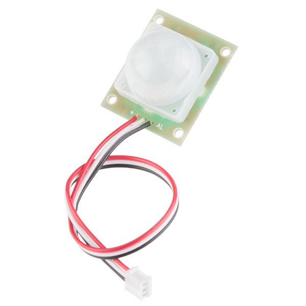
Passive infrared sensors are motion-detecting devices used in security systems across the world — even though you may not see them, they probably see you!
Using the PIR sensor is simple: power it up, connect a pull-up resistor to the open-collector signal pin, and watch for it to go low. The PIR can sense abrupt changes in scenery as far as 10 feet (~3m) away. Once your microcontroller is sensing movement, it can trigger a buzzer, text message, tweet or klaxon.
Take a look at this Simple Circuit video to see the PIR Motion Sensor in action!
Hardware Hookup
Ready to start hooking everything up? Check out the wiring diagram below to see how everything is connected.
Wiring Diagram for the Experiment
Note: The wire colors of the PIR motion sensor do not follow standard notation in terms of Ground, VCC and Signal. Please note that Red = VCC (5V), Black = Signal, and White = Ground.
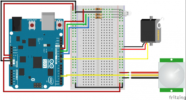
Having a hard time seeing the circuit? Click on the wiring diagram for a closer look.
Build Your Blynk App
The Blynk app half of this project should be pretty straightforward for you. Again, be sure to create a new app in Blynk and check your email for the authorization token for your sketch.
As with all of the Blynk apps that use the Arduino 101 board, add the BLE widget and open the settings to connect your phone to the board.
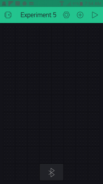
Once you have added the BLE widget, all you need to do is add three button widgets to your app and place/resize them to your taste.
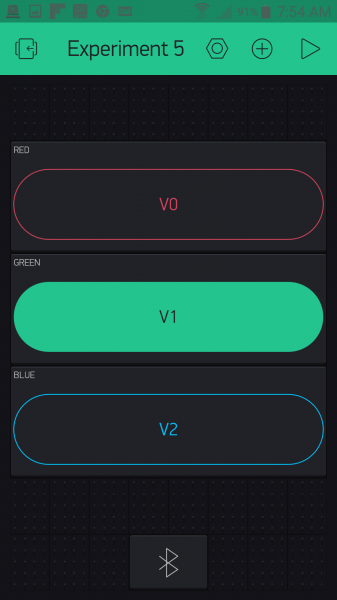
Each button will correspond to a color that you will see from the RGB LED (RED, GREEN and BLUE). We labeled each one accordingly and changed its color to match its name.
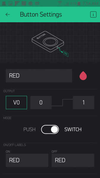
We then assigned each color a virtual pin to control. Here is what we used:
RED => Virtual Pin 0
GREEN => Virtual Pin 1
BLUE => Virtual Pin 2
The final task in setup of the buttons is to change each one to switch mode. This will keep the event from being triggered when you release the button and giving you a false value.
Here is what your completed RGB door key app should look like:
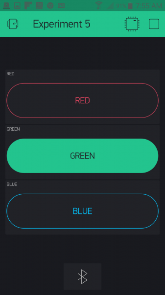
Uploading Your Sketch
Open the Arduino IDE software on your computer. Coding in the Arduino language will control your circuit.
You can type out or copy and paste the following code into the Arduino IDE. Hit upload, and see what happens!
language:cpp
/********************************************************************************
SparkFun Around-The-Home SIK Expansion Kit, Experiment 5
SparkFun Electronics
Product URL

Build a combination lock that detects when someone is present then displays a color on an RGB LED. The user has to input the color into a Blynk app to open a servo controlled latch.

This example is written by: Derek Runberg, Educational Technologist

This sketch was written by SparkFun Electronics, with lots of help from the Arduino community.
This code is completely free for any use.

View circuit diagram and instructions at:https://learn.sparkfun.com/tutorials/around-the-home-expansion-kit

********************************************************************************/

/* Comment this out to disable prints and save space */
#define BLYNK_PRINT Serial
#include <BlynkSimpleCurieBLE.h>
#include <CurieBLE.h>
#include <Servo.h>

Servo doorLatch;
BLEPeripheral  blePeripheral;


// You should get Auth Token in the Blynk App.
// Go to the Project Settings (nut icon).
char auth[] = "YOUR_AUTH_TOKEN";

const int RED_PIN = 13;
const int GREEN_PIN = 12;
const int BLUE_PIN  = 11;

const int MOTION_PIN = 3;
const int SERVO_PIN = 9;

int keyValue = 0;
int show;
boolean motion = false;

void setup()
 {
  Serial.begin(9600);
  blePeripheral.setLocalName("Exp_05");
  blePeripheral.setDeviceName("Exp_05");
  blePeripheral.setAppearance(384);

  Blynk.begin(blePeripheral, auth);

  blePeripheral.begin();

  // Set RGB LED pins as OUTPUT
  pinMode(13, OUTPUT);
  pinMode(12, OUTPUT);
  pinMode(11, OUTPUT);

  //set MOTION_PIN as INTPUT_PULLUP for motion sensor
  pinMode(MOTION_PIN, INPUT_PULLUP);

  //attach servo to SERVO_PIN
  doorLatch.attach(SERVO_PIN);

  //attach the interrupt to the motion pin
  attachInterrupt(MOTION_PIN, trigger, FALLING);
  doorLatch.write(10);
}

void loop()
{
  blePeripheral.poll();
  Blynk.run();

  if(motion == true){
    show = random(11,14);
    digitalWrite(show,HIGH);
    Serial.println(show);
    motion = !motion;
  }
}

//custom function called trigger
void trigger() {
  motion = !motion;
  detachInterrupt(MOTION_PIN);
}

BLYNK_WRITE(V0)
{
  keyValue = 0 + param.asInt(); // Get value as integer
  if (keyValue + show == 14) {
    doorLatch.write(90);
    digitalWrite(show, LOW);
    Serial.println("latch open");
    attachInterrupt(MOTION_PIN, trigger, FALLING);
  }
  else {
    keyValue = 0;
    doorLatch.write(10);
    Serial.println("latch closed");
  }
}

BLYNK_WRITE(V1)
{
  keyValue = 1 + param.asInt(); // Get value as integer
  if (keyValue + show == 14) {
    doorLatch.write(90);
    digitalWrite(show, LOW);
    Serial.println("latch open");
    attachInterrupt(MOTION_PIN, trigger, FALLING);
  }
  else {
    keyValue = 0;
    doorLatch.write(10);
    Serial.println("latch closed");
  }
}

BLYNK_WRITE(V2)
{
  keyValue = 2 + param.asInt(); // Get value as integer
  if (keyValue + show == 14) {
    doorLatch.write(90);
    digitalWrite(show, LOW);
    Serial.println("latch open");
    attachInterrupt(MOTION_PIN, trigger, FALLING);
  }
  else {
    keyValue = 0;
    doorLatch.write(10);
    Serial.println("latch closed");
  }
}
Code to Note
This Experiment uses a bunch of hardware from both the Expansion Kit and the SIK for the Arduino 101, and also presents a number of programming concepts to dive into using both Blynk and Arduino. Hope you have your programming hat on because here we go!
language:cpp
int keyValue = 0;
int show;
Most of the top half of the sketch you have seen before: setup of Blynk and the BLE setup. But, we create two global variables: one called keyVale, which we assign a value of 0, and the other called show, which will store which LED color we will be displaying to the person trying to unlock the latch.
attachInterrupt(MOTION_PIN,trigger,FALLING);
Interrupts are amazing things, but sometimes hard to wrap your mind around. Interrupts are a way of triggering a function when that pin acts a certain way. For example when a pin goes from HIGH to LOW, it is called FALLING. This all happens outside of the normal loop function, so things happen once and are not repeated over and over again as they would be if you used an if() statement in the loop. You pass the attachInterrupt() command three parameters: the pin number you are watching, the function you want triggered and finally the action it is watching for. Here are the actions you can look for:
FALLING— Pin state going from HIGH to LOWRISING— Pin state going from LOW to HIGHCHANGE— Any pin state change
A couple words of warning when using interrupts…
- Never use delay() in an interrupt trigger function
- Try to keep the triggered function as short as possible
- Interrupts can only be used on certain pins depending on the Arduino you use; on the Arduino 101 board, you can use 0 through 12.
language:cpp
void trigger() {
  motion = !motion;
  detachInterrupt(MOTION_PIN);
 }
The trigger() function is the function that is triggered by the interrupt. All that it does is flip-flop the motion Boolean variable and then detach the interrupt so that it doesn’t keep firing if you are standing in front of the motion sensor. That’s it, nice and short…but some would argue that even this is too long.
language:cpp
  if(motion == true){
    show = random(11,14);
    digitalWrite(show,HIGH);
    Serial.println(show);
    motion = !motion;
  }
The if() statement that is inside of the loop tracks if motion is true or false. If it is true, it generates a random number and is stored inside of the show variable. We then turn on the pin that corresponds to that random number. Finally, the motion variable is flopped to false to keep the if() statement from firing on the next loop.
language:cpp
BLYNK_WRITE(V0)
{
 keyValue = 0 + param.asInt(); // Get value as integer
 if (keyValue + show == 14) {
   doorLatch.write(90);
   digitalWrite(show, LOW);
   Serial.println("latch open");
   }
 else {
   keyValue = 0;
   Serial.println("latch closed");
  }
 }
The Blynk app library for Arduino uses a number of special functions that are called event functions. Basically they are triggered through data being sent by the Blynk app. In this case, when a value is written to virtual pin V0, the contents of this function are triggered. Inside of this event function we read the data sent from the app as an integer using the param.asInt() method.
We add a value to it for each progressive pin number. We do this because we want to make sure that if the app user presses the correct color the keyValue + show should equal 14. We use an if() statement to check this math. If it does equal 14, then the «key» is correct, and the servo unlatches. If the «key» is incorrect, the servo stays latched, and the keyValue is reset. If you look at the full sketch, you can see that we have three different event functions for the three RGB colors and colored buttons in the app.
Basically, when you press the button that matches the color of the RGB LED, the servo moves.
What You Should See
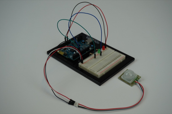
When you move in front of the PIR motion sensor the Arduino 101 board will generate a random color of the RGB LED. If you connect to the Blynk app over BLE and press the button that corresponds to the color of the RGB LED, the servo will «unlock» or move to the 90-degree position. To «lock» the servo again press the same color again, this should also put the 101 back in a state of watching for motion to display a color again!
[INSERT VIDEO]
Troubleshooting
Blynk Shortcut!
If you are having troubles duplicating the functionality above in the Blynk app, scan this QR code with Blynk to get a clone of this experiment!

Program Not Uploading
This happens sometimes; the most likely cause is a confused serial port. You can change this in Tools > Serial Port >
Also, if you get a Timeout error or the IDE could not find your 101 board, try pressing the Master Reset button on the 101, wait around 10 seconds and try re-uploading your sketch.
Still No Success
A broken circuit is no fun. Send us an email, and we will get back to you as soon as we can: techsupport@sparkfun.com
Experiment 6: Controlling a Solenoid Valve With a MOSFET
Introduction
A big part of home automation is being able to control devices and circuits that operate at a lot higher voltage and current than a standard microcontroller. If you hooked up the GPIO pin of an Arduino 101 board to 12 volts, you would destroy your board. So, how is it done?
The answer is using something called a MOSFET! In this experiment we will use the Arduino 101 and Blynk to control a solenoid valve using a MOSFET and build a BLE-controlled sprinkler timer! Hope you brought your swimsuit because you are going to need it!
Parts Needed
You will need the following parts:
- 1x Breadboard (From your Arduino 101 SIK)
- 1x Arduino 101 Board (From your Arduino 101 SIK)
- 1x MOSFET
- 1x Solenoid Valve
- 2x Female Disconnects
- 1x 12V Wall Wart Power Adapter
- 2x 10k Ohm Resistor (From your Arduino 101 SIK)
- 8x Jumper Wires (From your Arduino 101 SIK)
Note: To complete building the circuit for this experiment you will need a pair of pliers to crimp connectors to the end of your jumper wires.
Didn’t Get the Around-the-Home Expansion Kit?
If you are conducting this experiment and didn’t get the Around-the-Home Expansion Kit, we suggest using these parts:

48
2
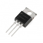
4
Retired
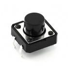
4
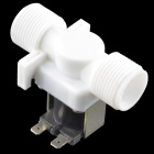
7
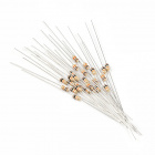
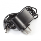
13
Retired
You will also need an Arduino 101 board.
9
Retired
Suggested Reading
Before continuing with this experiment, we recommend you be familiar with the concepts in the following tutorials:
- Light-Emitting Diodes — Learn more about LEDs
- Switch Basics — Learn more about buttons and switches
Introducing the MOSFET
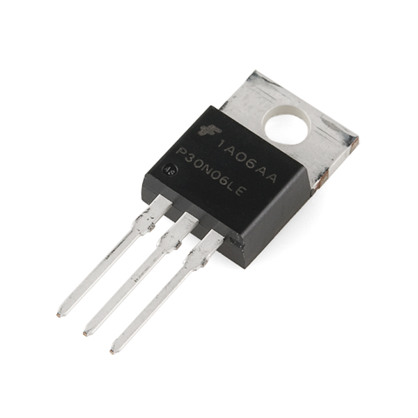
In Experiment 11 from the SparkFun Inventor’s Kit for the Arduino 101 experiment guide, you learned about using transistors and that they were like a switch that allows you to control larger loads of electricity with a much smaller current and/or voltage in a safe way, protecting your Arduino board from harm. A MOSFET does the same thing, and, in fact, we are using them the same way. They are hooked up differently, and the MOSFET can handle a much larger load than the puny transistor from your Inventor’s Kit.
Similar to the transistor, the MOSFET has three legs, but they have different names. If you place the MOSFET on the table with its flange side down and the legs pointing toward you, the pins are named as follows:
LEFT = Gate
MIDDLE = Drain
RIGHT = Source
Here is a reference image from the datasheet of the MOSFET we use in this kit:
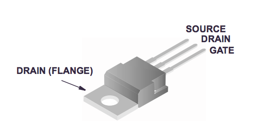
To use the MOSFET you connect the Gate pin to a GPIO pin of a microcontroller — in this case, your Arduino 101 board. The Drain is connected to the load’s ground line, and the Source is connected to the system’s Ground. When you energize, or pull the Gate HIGH, you let current through the MOSFET in through the Drain and out through the Source.
To get a more in-depth background on what MOSFETs are and how they work, check out the «According to Pete» video below!
Thank you, Pete! Now back to your regularly scheduled programming!
Introducing the Solenoid Valve
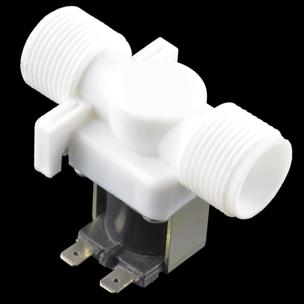
Have you ever wanted to control the flow of a liquid using your computer or microcontroller? Yeah, us too! Well, here’s how: This is a 12V solenoid-controlled fluid valve. Simply connect a fluid source to the ¾» threaded inlet, and it will interrupt the flow until 12V is applied to the fast-on connectors on the solenoid.
By now you are probably connecting the dots as to why we also covered the MOSFET in that this valve functions using 12 volts, much too high to run through the GPIO pins of the Arduino 101 board. So, we will control this valve using the MOSFET and a 12V wall power supply.
When you connect this valve to 12 volts and Ground, the coil inside of it gets energized and pulls the valve open, allowing water that is under pressure to flow through it. Yep, that’s right; for this valve to work, the water you are controlling needs to be under pressure. Not a problem for our application, as we are going to be building a sprinkler timer.
Connecting the Valve
«But, wait!» you may be asking, «How do I connect the valve to the rest of my circuit with those funny tabs?» Great question! We have included female disconnects that are pretty easy to add to jumper wires if you have a pair of pliers. Grab two jumper wires, two disconnects and your pliers, and let’s build some custom jumper wires!
First start by sliding the female disconnect over one end of a jumper wire and press it as far as it will go. Then take your plier and crimp the disconnect onto the wire as hard as you can. We don’t want the disconnect coming loose!
OK, that’s it! Rinse and repeat for the second wire, and you should be good to go! Give your new disconnects a good test to make sure they will stay on the wire, and let’s jump to the next steps.
Hardware Hookup
Ready to start hooking everything up? Check out the wiring diagram below to see how everything is connected.
Wiring Diagram for the Experiment
Note: The Arduino 101 board must be plugged into the 12V wall power supply for the solenoid valve to function properly!
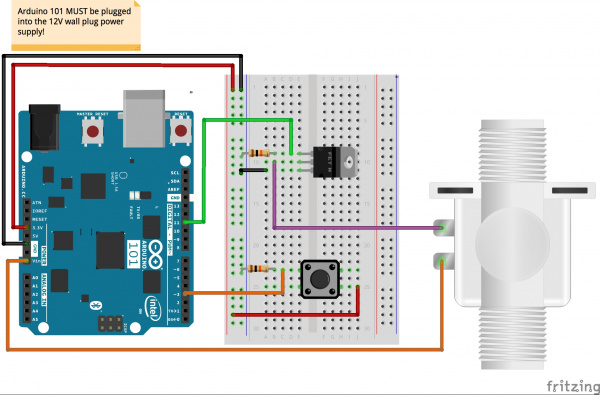
Having a hard time seeing the circuit? Click on the wiring diagram for a closer look.
Note: This circuit is designed for demonstration and short time use in its current form. For long term use we recommend adding this diode as a flyback diode to protect your MOSFET long term.
Powering Your Project
When you start to build projects that use either higher current or voltage levels that exceed the standard operational levels that the Arduino 101 board can source from a USB cable, an alternative power supply will be needed. In fact, you have probably been dangerously close using the BLE and controlling circuits in the past four experiments.
In this case, we are using a solenoid valve that requires 12V to operate. The good thing is that the Arduino 101 board can be powered by an external power supply in the range of 7 to 14 volts through the barrel jack on the board. This kit includes a 12V power supply just for this reason!
Once you plug the Arduino 101 board into the 12V power supply, it will turn the board on, and you will have access to both the 5V and 3.3V power rails. But now your VIN pin will be 12V, and you can use that pin to power your solenoid!
WARNING: You will be using a higher voltage (12V) power supply in this experiment. Please be aware that wiring a voltage of this level to any of the GPIO pins (0-13 and A0-A5) will cause permanent damage to your Arduino 101 board.
Build Your Blynk App
This Blynk app is a little more complicated than in your previous projects. You will be using the Time Input widget to set the Real-Time Clock (RTC) on the Arduino 101 board. For more details on that, or a quick refresher, you can reference Experiment X of the SIK guide for the Arduino 101 board. This app will allow you to set the RTC and then set a timer to control the solenoid valve to open and close at given time intervals to water your favorite tomato plant — or to control a water feature in your backyard.
This capitalizes on the internal memory and global variables so that you can connect to your project, set the times, disconnect and not worry about it.
As with all of the Blynk apps that use the Arduino 101 board, add the BLE widget and open the settings to connect your phone to the board.
Once you have added the BLE widget, we will add two different Time Input widgets. These widgets allow for you to set the time and create timers that schedule functions to happen at given times. We will first add both Timer Input widgets to your app. These cannot be resized, so place them in a way that makes sense to you.

Open one of the Time Input widgets and name it «Set System Clock» and its output to pin V0. Set the format as «HH:MM — AM/PM». We changed no other setting after that. This input is what you will use to set the RTC to your current time. You will need to do this any time that your 101 loses power, or is reset.
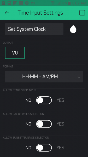
Open the second Time Input widget. This will be the timer control input. We labeled ours «Control Timer» and set the output to pin V1 with the format as «HH:MM». The only other setting we changed was to allow Start and Stop times.
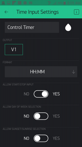
That’s it! Your completed app should look something like this when you run it:
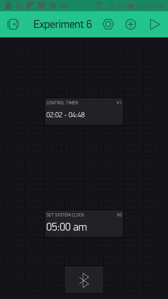
When you click on your «Set System Clock» it will allow you to set the time as shown below.
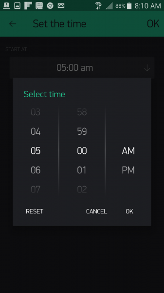
Your control timer interface will look something like this:
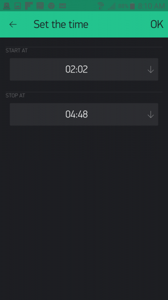
Now, let’s get the Arduino sketch uploaded so that you won’t have to worry about watering your lawn tomorrow.
Upload Your Sketch
Open the Arduino IDE software on your computer. Coding in the Arduino language will control your circuit.
You can type out or copy and paste the following code into the Arduino IDE. Hit upload, and see what happens!
language:cpp
/********************************************************************************
SparkFun Around-The-Home SIK Expansion Kit, Experiment 6
SparkFun Electronics
Product URL

Set the time of the Real-time-clock on the Arduino 101 using Blynk then set a timer to control a solenoid valve to control your sprinkers.

This example is written by: Derek Runberg, Educational Technologist

This sketch was written by SparkFun Electronics, with lots of help from the Arduino community.
This code is completely free for any use.

View circuit diagram and instructions at:https://learn.sparkfun.com/tutorials/around-the-home-expansion-kit

********************************************************************************/

/* Comment this out to disable prints and save space */
#define BLYNK_PRINT Serial
#include <CurieTime.h>
#include <BlynkSimpleCurieBLE.h>
#include <CurieBLE.h>

BLEPeripheral  blePeripheral;

// You should get Auth Token in the Blynk App.
// Go to the Project Settings (nut icon).
char auth[] = "YOUR_AUTH_TOKEN";


int startHour, startMinute, stopHour, stopMinute;
int override = false;

const int BUTTON_PIN = 3;
const int VALVE_PIN = 11;

void setup()
{
  Serial.begin(9600);

  blePeripheral.setLocalName("Exp_06");
  blePeripheral.setDeviceName("Exp_06");
  blePeripheral.setAppearance(384);

  pinMode(BUTTON_PIN, INPUT);
  pinMode(VALVE_PIN, OUTPUT);
  Blynk.begin(blePeripheral, auth);

  blePeripheral.begin();
  attachInterrupt(3,testValve,CHANGE);
}

void loop()
{
    //if start time matches...
    if (hour() == startHour && minute() == startMinute) {
      digitalWrite(VALVE_PIN, HIGH);
    }
    //if stop time matches...
    if (hour() == stopHour && minute() == stopMinute) {
      digitalWrite(VALVE_PIN, LOW);
    }
  blePeripheral.poll();
  Blynk.run();
}

void testValve(){
  if(digitalRead(BUTTON_PIN) == HIGH){
    digitalWrite(VALVE_PIN, HIGH);
    Serial.println("test fire");
  }
  else{
    digitalWrite(VALVE_PIN, LOW);
  }
}

//set clock event
BLYNK_WRITE(V0) {
  TimeInputParam t(param);

  // Set the RTC on the Arduino 101
  setTime(t.getStartHour(), t.getStartMinute(), 0, 2, 2, 2015);
}

//event function for timer
BLYNK_WRITE(V1) {
  TimeInputParam t(param);

  // Process start time
  if (t.hasStartTime())
  {
    startHour = t.getStartHour();
    startMinute = t.getStartMinute();
  }

  // Process stop time
  if (t.hasStopTime())
  {
    stopHour = t.getStopHour();
    stopMinute = t.getStopMinute();
  }
}
Code to Note
#include <CurieTime.h>
The Arduino 101 board, and specifically the Intel® Curie chip that is on the board, has its own Real-Time Clock (RTC), which we end up using in this project. To interact with the RTC, we need to add the CurieTime library that is included with Arduino when you install the Arduino 101 board definitions.
int startHour, startMinute, stopHour, stopMinute;
We create a number of empty global variables to start with in a bit of a different way. If you are going to create a number of variables of the same data type, you can actually list them out separated by commas in this fashion.
language:cpp
const int BUTTON_PIN = 3;
const int VALVE_PIN = 11;
We created two global constants to store the pin numbers for each component.
language:cpp
//set clock event
BLYNK_WRITE(V0) {
  TimeInputParam t(param);

  // Set the RTC on the Arduino 101
  setTime(t.getHour, t.getMinute, t.getSecond, 2, 2, 2015);
}
When you input a time into the Clock Set widget in your app, that time is written to the virtual pin 0 or V0. We then create a TimeInputParam object called t. We then set the RTC of the Arduino 101 board using the setTime() function and pass it the time parameters from t.
language:cpp
     //if start time matches...
     if(hour() == startHour && minute() == startMinute){
     digitalWrite(VALVE_PIN,HIGH);
    }
     //if stop time matches...
     if(hour() == stopHour && minute() == stopMinute){
     digitalWrite(VALVE_PIN,HIGH);
   }
We use a series of if() statements to check against the current time and the start time variables captured from the start and stop time values received over pin V1 from the Control Timer widget and stored in the global start and stop variables.
language:cpp
 BLYNK_WRITE(V1) {
  TimeInputParam t(param);

  // Process start time
  if (t.hasStartTime())
  {
   startHour = t.getStartHour();
   startMinute = t.getStartMinute();
  }

 // Process stop time
 if (t.hasStopTime())
 {
  stopHour = t.getStopHour();
  stopMinute = t.getStopMinute();
 }
}
We capture the start and stop times over virtual pin V1 from the Control Timer widget. We again create a local TimeInputParam object, which holds the time data from pin V1. Then, using a series of if() statements checking for a start and stop time, we store those start and stop times in our global variables.
What You Should See
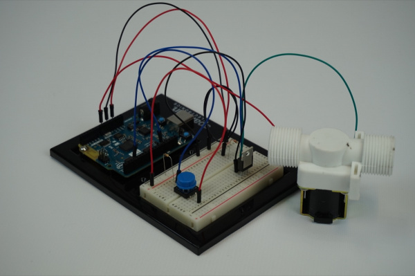
You shouldn’t actually see anything happen right away. If you press down on the button in the circuit, which is the manual override, it should open the valve. If you press the button again, the valve will close.
If you connect to the Blynk app, you can set the Real-Time Clock on the Arduino 101 board, as well as a scheduled start and stop time. Set the time for your local time and then a start time about three minutes or so from that time, with a stop time five minutes later. From here you should be able to close the Blynk app as long as the Arduino 101 board stays powered up. You can do this because the Real-Time Clock on the Arduino 101 was set by the Blynk app, and all of the control logic for the watering system is on the Arduino side of the sketch.
The valve should turn on in three minutes and then off again in five more! No more forgetting that your sprinklers are running!
[INSERT VIDEO]
Troubleshooting
Blynk Shortcut!
If you are having troubles duplicating the functionality above in the Blynk app, scan this QR code with Blynk to get a clone of this experiment!

Program Not Uploading
This happens sometimes; the most likely cause is a confused serial port. You can change this in Tools > Serial Port >
Also, if you get a Timeout error or the IDE could not find your 101 board, try pressing the Master Reset button on the 101, wait around 10 seconds and try re-uploading your sketch.
Still No Success
A broken circuit is no fun. Send us an email, and we will get back to you as soon as we can: techsupport@sparkfun.com
Experiment 7: Moisture Sensor
Introduction
In this experiment, you’ll use the SparkFun soil moisture sensor to alert you when your plants are getting sad and need a bit of water to cheer up, or if your watering system in Experiment 6 is going on the fritz.
Remember Experiment 3? In that experiment, you built a voltage divider circuit to read light intensity data as voltage from a photoresistor. Good news: the SparkFun moisture sensor has an onboard voltage divider — it does that part for you! All you need to do is power it and read the analog values coming from its signal (third) pin.
We will use that voltage reading to detect the level of moisture in the soil (as water conducts electricity) and build a dashboard for your most coveted house plant. Hope you have your green thumb ready!
Suggested Reading
The following tutorials provide in-depth background on some of the hardware concepts in this experiment:
- 101 SIK Experiment 7: Reading a Photoresistor
- Voltage Dividers
- Soil Moisture Sensor Hookup Guide
Parts Needed
You will need the following parts for this experiment:
- 1x Arduino 101 Board (From your Arduino 101 SIK)
- 1x Breadboard (From your Arduino 101 SIK)
- 1x Soil Moisture Sensor
- 5x Jumper Wires (From your Arduino 101 SIK)
- 1x Pocket Screw Driver (Not Included)
Didn’t Get the Around-the-Home Expansion Kit?
If you are conducting this experiment and didn’t get the Around-the-Home Expansion Kit, we suggest using these parts:
Headers or No Headers?
Note:If you are buying the breakout boards (Moisture Sensor) seperate from this kit you will also need to buy screw terminals and assemble (solder) them to your board yourself.
You will also need an Arduino 101 board.
9
Retired
Introduction to the Soil Moisture Sensor
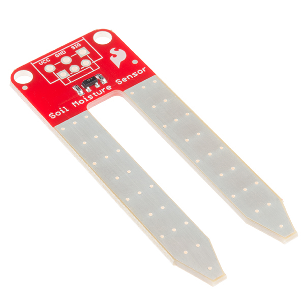
The SparkFun Soil Moisture Sensor is a simple breakout board for measuring the moisture in soil and similar materials. The soil moisture sensor is straightforward to use. The two large, exposed pads function as probes for the sensor, together acting as a variable resistor. The more water that is in the soil, the better the conductivity between the pads will be, which will result in a lower resistance and a higher SIG (output voltage).
To get the SparkFun Soil Moisture Sensor functioning, all you need to do is connect the VCC and GND pins to your Arduino 101. You will receive a SIG out, which you will read using an Analog Input pin (A0), which will depend on the amount of moisture in the soil. Oh, and you’ll also need a bit of dirt in a pot to test it all out!
One commonly known issue with soil moisture sensors is their short life span when exposed to a moist environment. To combat this, we’ve had the PCB coated in Gold Finishing (ENIG, or Electroless Nickel Immersion Gold), which will extend the life of your sensor.
->
Hardware Hookup
Ready to start hooking everything up? Check out the wiring diagram below to see how everything is connected.
Wiring Diagram for the Experiment
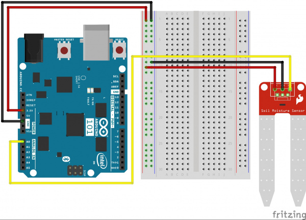
Having a hard time seeing the circuit? Click on the wiring diagram for a closer look.
Note: The headers on the soil sensor are a screw-terminal type. You’ll need a small (jewelry- or electronics-sized) flat screwdriver. If you don’t have one on hand, you can probably still get the jumper wires into the header slots, but they won’t be as secure.
Build Your Blynk App
The Blynk app half of this project should be pretty straightforward for you, but it is good experience using the LCD widget and writing data to it. Again, be sure to create a new app in Blynk and check your email for the authorization token for your sketch.
As with all Blynk apps when you are using the Arduino 101, be sure to add the BLE widget into your app and make sure Bluetooth and Location are turned on for your phone.
Next add the LCD widget and place it wherever you like. We centered ours, as it will be the only widget other than the BLE one on the screen.
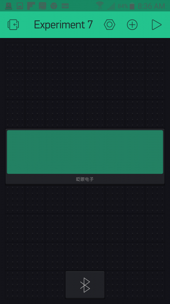
Now open the settings for the LCD widget. You have two pins that you need to assign, and each one has its own row in the LCD. Set the first one to V0 and the second one to V1 as shown. Next set the reading rate; since moisture monitoring is a pretty slow process, a five-second period is fine, and you could probably even go longer. Finally comes the fun part: the message itself!
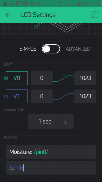
There are two rows to the message. In the first one we are going to display the raw moisture value. You can insert whatever test you want; we added «moisture: » and then /pin0/. Whenever you see /pin0/ or /pin1/ that is a placeholder for the data being sent to pins V0 and V1. Blynk will insert that data in its place. So, the second row will be whatever string of text is sent to pin V1 and will change as the moisture level changes.
That’s it! We told you this app would be simple, but powerful in terms of displaying data. Your app should look something similar to this before you upload and run your sketch.
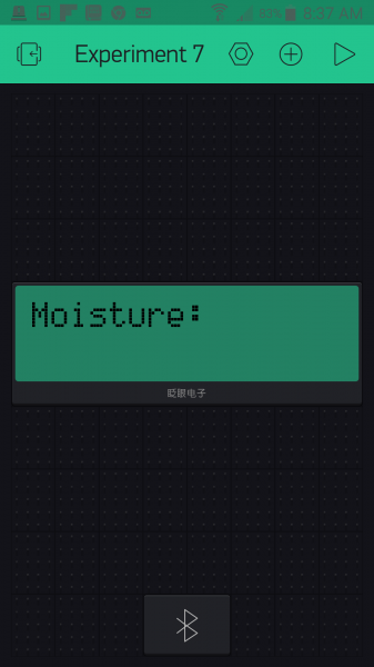
Uploading Your Sketch
Open the Arduino IDE software on your computer. Coding in the Arduino language will control your circuit.
You can type out or copy and paste the following code into the Arduino IDE. Hit upload, and see what happens!
language:cpp
/********************************************************************************
SparkFun Around-The-Home SIK Expansion Kit, Experiment 7
SparkFun Electronics
Product URL

Detect the soil moisture of a potted plant using the Arduino 101 and then display whether you should water it or not through a Blynk app.

This example is written by: Derek Runberg, Educational Technologist

This sketch was written by SparkFun Electronics, with lots of help from the Arduino community.
This code is completely free for any use.

View circuit diagram and instructions at:https://learn.sparkfun.com/tutorials/around-the-home-expansion-kit

********************************************************************************/

//#define BLYNK_USE_DIRECT_CONNECT

/* Comment this out to disable prints and save space */
#define BLYNK_PRINT Serial


#include <BlynkSimpleCurieBLE.h>
#include <CurieBLE.h>

// You should get Auth Token in the Blynk App.
// Go to the Project Settings (nut icon).
char auth[] = "YOUR_AUTH_TOKEN";

BLEPeripheral  blePeripheral;

//Moisture preset values
int dry = 100;
int damp = 600;

//sensor pin constant set at A0
const int SENSOR_PIN = A0;

//create a BlynkTimer object called timer
BlynkTimer timer;

void setup()
{
  // Debug console
  Serial.begin(9600);

  delay(1000);

  blePeripheral.setLocalName("Exp_07");
  blePeripheral.setDeviceName("Exp_07");
  blePeripheral.setAppearance(384);

  Blynk.begin(blePeripheral, auth);

  blePeripheral.begin();

  Serial.println("Waiting for connections...");
  //set interval of 1 second to trigger the sendValues function
 timer.setInterval(500L, sendValues);
}

void loop()
{
  blePeripheral.poll();
  Blynk.run();
}

//custom function called sendValues
void sendValues() {
  //read moisture sensor value


}

BLYNK_READ(V0){
  int moisture = analogRead(A0);
  //write raw value to Blynk on pin V0
  Blynk.virtualWrite(V0, moisture);

  //if moisture is less that or equal to dry...
  if (moisture <= dry) {
    //write the string "I'm parched" to virtual pin 1
    Blynk.virtualWrite(V1, "I'm Parched!");
  }
  //else if moisture is greater than or equal to damp...
  else if (moisture >= damp) {
    //write the string "I'm drowning" to virtual pin 1
    Blynk.virtualWrite(V1, "I'm Drowning!");
  }
  else {
    //write the string "I'm good!" to virtual pin 1
    Blynk.virtualWrite(V1, "I'm Good!");
  }
}
Code to Note
If Arduino is not new to you, then you are well aware of the delay() command. It is how you slow down your sketch or deal within timing of things. But, as you may have noticed in previous sketches, sometimes using a delay() will cause latency, or the piling up of delay commands that add up to your sketch acting sluggish and not doing what you expect. Working with Blynk is really sensitive to this! The way this problem is solved is by using event functions within the Blynk library!
BLYNK_READ(V0){....}
Certain Blynk widgets have timed intervals at which they read or poll specific pins, either physical or virtual. There is an event function called BLYNK_READ(), which is triggered every time one of these widgets reads that pin. In this case, the LCD widget reads pin V0 once every five seconds. You can set this interval with the widget settings in your app. In this use case of a moisture sensor and a potted plant, you would probably want a longer interval, but we shortened it to make it more responsive for a better demonstration.
language:cpp
int moisture = analogRead(A0);
//write raw value to Blynk on pin V0
Blynk.virtualWrite(V0, moisture);
Within the BLYNK_READ() event function we read the moisture sensor on pin A0 and store it in a local variable called moisture. We then write this value to virtual pin V0 every time the Blynk app calls a read over pin V0. In this case, as stated before, every five seconds.
language:cpp
  //if moisture is less that or equal to dry...
  if (moisture <= dry) {
    //write the string "I'm parched" to virtual pin 1
    Blynk.virtualWrite(V1, "I'm Parched!");
  }
  //else if moisture is greater than or equal to damp...
  else if (moisture >= damp) {
    //write the string "I'm drowning" to virtual pin 1
    Blynk.virtualWrite(V1, "I'm Drowning!");
  }
  else {
    //write the string "I'm good!" to virtual pin 1
    Blynk.virtualWrite(V1, "I'm Good!");
  }
}
We use a series of if() statements to write different strings depending on the moisture level, from «I’m Parched» to «I’m Drowning» — all using the Blynk.virtualWrite() method, but this time to pin V1. The great thing about virtual pins is that they are more buckets than pins. They can store pretty much any data you want to write to them. In this case, whole strings of characters.
What You Should See
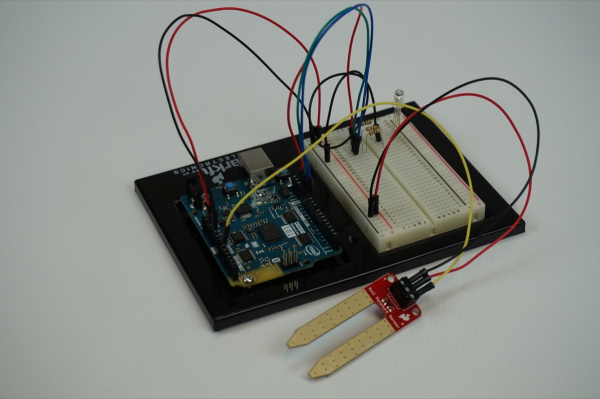
Now, plug your project into the wall using the power supply and insert the moisture sensor into a potted plant, or if you don’t have a green thumb, maybe just some soil outside.
Then open your Blynk app and connect to your project via BLE. The LCD screen on your app should display two lines. The first line should say «Moisture: XXX» with XXX being a number value. The second string should be one of the statements we wrote to pin V1…»I’m Parched!» or «I’m Good!» or «I’m Drowning!»
Add water to the soil and see what happens!
[Video]
Troubleshooting
Blynk Shortcut!
If you are having troubles duplicating the functionality above in the Blynk app, scan this QR code with Blynk to get a clone of this experiment!

Experiment 8: Atmospheric Conditions with BME280
Introduction
The sensor used in this experiment is pretty sophisticated. The BME280 reads barometric pressure, temperature and humidity. It can even extrapolate altitude based on pressure changes! It communicates all that data to the Arduino 101 using a serial protocol called I2C (Inter-Integrated Circuit). This sensor has library support for Arduino and works out of the box. In this experiment we will be building an environmental monitoring system with the BME280 and displaying the data in Blynk. With this device you will be able to carry around and monitor the atmospheric conditions in real time. This is great for figuring out heating and cooling issues, checking your altitude, or even just checking the temperature around you if you decide to make it portable in a backpack…or dare I say fanny pack?
Suggested Reading
The following tutorial provides in-depth background on some of the hardware concepts in this experiment:
- I2C Communication
- BME280 Hookup Guide
Parts Needed
You will need the following parts for this experiment:
- 1x Arduino 101 Board (From your Arduino 101 SIK)
- 1x Breadboard (From your Arduino 101 SIK)
- 1x The BME280 Atmospheric Sensor
- 6x Jumper Wires (From your Arduino 101 SIK)
Didn’t Get the Around-the-Home Expansion Kit?
If you are conducting this experiment and didn’t get the Around-the-Home Expansion Kit, we suggest using these parts:
Headers or No Headers?
Note:If you are buying the breakout boards (BME280 Breakout) seperate from this kit you will also need to buy female breakaway pins and assemble (solder) the pins to your board yourself.
You will also need an Arduino 101 board.
9
Retired
Introduction to the BME280
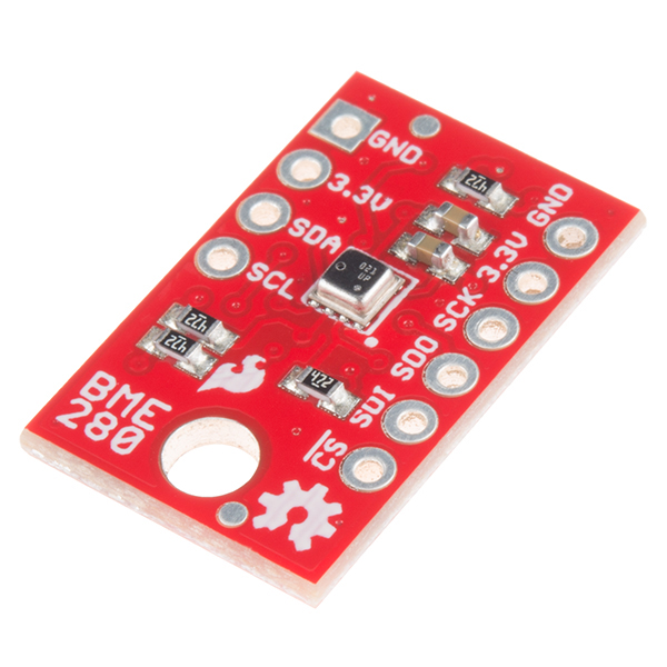
The SparkFun BME280 Atmospheric Sensor Breakout is an easy way to measure aspects of the atmosphere around you, including pressure, humidity and air temperature. All of this is combined into a petite package called a breakout board.
The 3.3V breakout is power-efficient, using as little as 5µA (that’s 1/1,000,000 of an amp!) when idling and less than 1mA when taking measurements. There are 10 pins on the breakout board, but six is the maximum ever used at one time.
In this experiment you will work with the BME280 to read the temperature, pressure and humidity of the room as well as your altitude based off of the atmospheric pressure and print it out on the LCD screen. Finally, in the Touch of Blynk section you will use your BME280 to send atmospheric data to your Blynk app.
Hardware Hookup
Is it hot in here, or is it just me? Let’s find out using this sensor, but first you need to hook it up!
Wiring Diagram for the Experiment
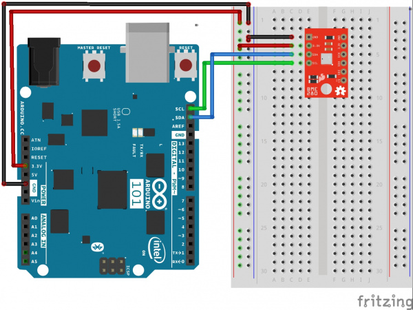
Having a hard time seeing the circuit? Click on the wiring diagram for a closer look.
Build Your Blynk App
This Blynk app is going to start looking more and more like a professional-grade app. We will be adding tabs to your app so that you can switch between live line graphs of the temperature, humidity and pressure on the first page and a table of that data on the second tab. You can add tabs to your app using the Tabs widget under the Interface section of the Widget Box menu. In fact, take a bit to check out the other interface options you have at your disposal. You have actually already used one in the Time Input widget. These are really fun and add a certain amount of polish to your app.
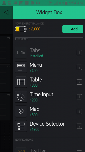
You add your Tabs widget like anything else, but it auto-populates itself at the top. From there you can open the settings like any other widget, name your tabs and even add more. We named our two tabs «Live Data» and «Logged Data.»
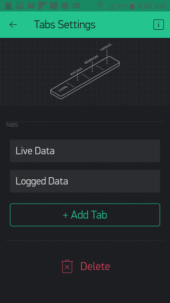
Now, working on the «live data» tab, we add three line graphs — one for each of the pieces of data that we are graphing: Temperature, Humidity and Pressure. We set all three to line graphs.
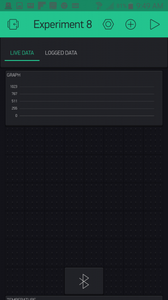
Temperature is set to pin V0, Humidity is pin V1, and Pressure is pin V2. You can also change the line colors to your taste. Also note that we set our expected value range to something that makes sense. Temperature, for example, is a range from 0 to 110, and humidity is 0 to 100.
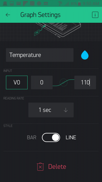
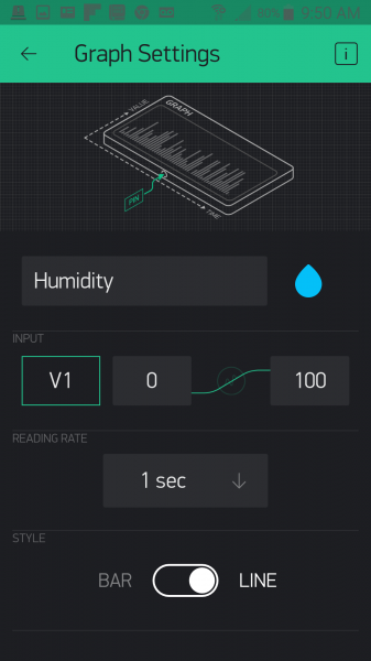

Next, we head over to the «Logged Data» tab and add a Table Widget. We want to connect the table to any data we send it over pin V3 in our Arduino sketch. In terms of the options, we set the columns to «name|value» and do not allow reordering since we will not be time-stamping this table (perhaps that is something you would like to add later).
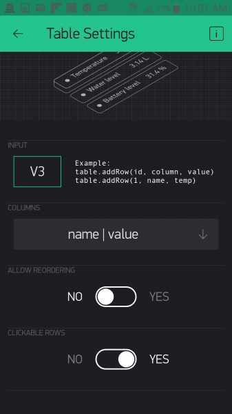
With that we are done with our app setup, and it is now time to get the code uploaded and start sending data to the app so you can use this project to explore the atmospheric data around you!
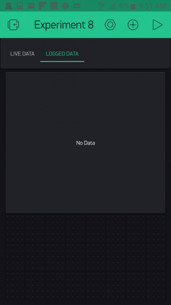
Uploading Your Sketch
Note: This project uses the BME280 sensor, which has an Arduino library associated with it that needs to be installed! Please take a moment and follow this tutorial to install the library before moving on with uploading your sketch to your Arduino 101 board.
Installing the BME280 Arduino Library
You can copy and paste the following code into the Arduino IDE. Hit upload, and see what happens!
language:cpp
/********************************************************************************
SparkFun Around-The-Home SIK Expansion Kit, Experiment 8
SparkFun Electronics
Product URL

Read the Humidity, Temperature and atmospheric pressure of your house and then log and graph it real time in a Blynk app.

This example is written by: Derek Runberg, Educational Technologist

This sketch was written by SparkFun Electronics, with lots of help from the Arduino community.
This code is completely free for any use.

View circuit diagram and instructions at:https://learn.sparkfun.com/tutorials/around-the-home-expansion-kit

********************************************************************************/

//#define BLYNK_USE_DIRECT_CONNECT

/* Comment this out to disable prints and save space */
#define BLYNK_PRINT Serial

#include "SparkFunBME280.h"
#include "Wire.h"
#include <BlynkSimpleCurieBLE.h>
#include <CurieBLE.h>

// You should get Auth Token in the Blynk App.
// Go to the Project Settings (nut icon).
char auth[] = "YOUR_AUTH_TOKEN";

BLEPeripheral  blePeripheral;
BME280 mySensor;
BlynkTimer timer;

int temperature, humidity, pressure;
int rowIndex = 0;

void setup()
{
  //BME280 configuration
  mySensor.settings.commInterface = I2C_MODE;
  mySensor.settings.I2CAddress = 0x77;

  mySensor.settings.runMode = 3; //  3, Normal mode
  mySensor.settings.tStandby = 0; //  0, 0.5ms
  mySensor.settings.filter = 0; //  0, filter off
  //tempOverSample can be:
  //  0, skipped
  //  1 through 5, oversampling *1, *2, *4, *8, *16 respectively
  mySensor.settings.tempOverSample = 1;
  //pressOverSample can be:
  //  0, skipped
  //  1 through 5, oversampling *1, *2, *4, *8, *16 respectively
  mySensor.settings.pressOverSample = 1;
  //humidOverSample can be:
  //  0, skipped
  //  1 through 5, oversampling *1, *2, *4, *8, *16 respectively
  mySensor.settings.humidOverSample = 1;

  //start the sensor
  mySensor.begin();

  // Debug console
  Serial.begin(9600);

  delay(1000);

  blePeripheral.setLocalName("Exp_08");
  blePeripheral.setDeviceName("Exp_08");
  blePeripheral.setAppearance(384);

  Blynk.begin(blePeripheral, auth);

  blePeripheral.begin();

  Serial.println("Waiting for connections...");
  //set interval of 1 second to trigger the sendValues function
  timer.setInterval(100L, sendValues);
 }

void loop()
{
  blePeripheral.poll();
  Blynk.run();
}

//custom function called sendValues
void sendValues() {
  //write temperature and humidity to table

}

BLYNK_READ(V0){
  temperature = mySensor.readTempF();
  Blynk.virtualWrite(V0,temperature);
}

BLYNK_READ(V1){
  humidity = mySensor.readFloatHumidity();
  Blynk.virtualWrite(V1,humidity);
  Blynk.virtualWrite(V3, "add", rowIndex, "humidity%", humidity);
  rowIndex++;
}

BLYNK_READ(V2){
  pressure = mySensor.readFloatPressure() / 100;
  Blynk.virtualWrite(V2,pressure);
}
Code to Note
This sketch is not that complicated in terms of anything new from the Blynk API; it is using the BME280 in Arduino that will be the new kid on the block for the Code to Note.
#include "SparkFunBME280.h"
To simplify the programming in Arduino to use the BME280, we created a library to keep things clean and straightforward for you. You have to include that library in your sketch to be able to use it.
BME280 mySensor;
You then create a BME280 object. We called ours «mySensor,» but you can call it whatever you like!
language:cpp
  //BME280 configuration
  mySensor.settings.commInterface = I2C_MODE;
  mySensor.settings.I2CAddress = 0x77;

  mySensor.settings.runMode = 3; //  3, Normal mode
  mySensor.settings.tStandby = 0; //  0, 0.5ms
  mySensor.settings.filter = 0; //  0, filter off
  //tempOverSample can be:
  //  0, skipped
  //  1 through 5, oversampling *1, *2, *4, *8, *16 respectively
  mySensor.settings.tempOverSample = 1;
  //pressOverSample can be:
  //  0, skipped
  //  1 through 5, oversampling *1, *2, *4, *8, *16 respectively
  mySensor.settings.pressOverSample = 1;
  //humidOverSample can be:
  //  0, skipped
  //  1 through 5, oversampling *1, *2, *4, *8, *16 respectively
  mySensor.settings.humidOverSample = 1;
The BME280 is a great sensor because you have a lot of options in terms of how to use it, and it can be configured in a number of different ways. But, it can also be daunting when you first approach using it. If you want to learn more about these settings, we highly recommend reading the Hookup Guide for the BME280; otherwise just leave everything as is.
mySensor.begin();
After all of that we start using the sensor by calling mySensor.begin(). This applies all of the settings changes and starts reading values from the sensor.
language:cpp
BLYNK_READ(V0){
 temperature = mySensor.readTempF();
 Blynk.virtualWrite(V0,temperature);
}
As in the previous experiment, we put the BLYNK_READ() event function to use. This time each graph has its own event function. In our example code they are all set to the same timing, but you could easily change each one to make sense for your application. For example, you could probably get away with not tracking pressure as often as you would temperature or humidity.
language:cpp
 Blynk.virtualWrite(V3, "add", rowIndex, "humidity%", humidity);
 rowIndex++;
You may have noticed that the humidity graph event function (reading on pin V1) has a little extra code in it. This is because we decided to track the humidity percentage in a table on the «Logged Data» tab. To add data to a table you use the virtualWrite() method, but add a few extra parameters. You add the pin that is connected to the table — in this case V3 — the command to «add» to the table, the row you want to add data to, the title of the row and finally the data. We are adding a new row in a running manner by incrementing a variable called rowIndex.
What You Should See
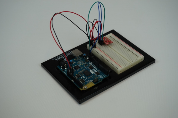
[Video]
As a bonus to this experiment, we added a Map Widget just below the table to give our location, which is based off of our phone. Check it out!
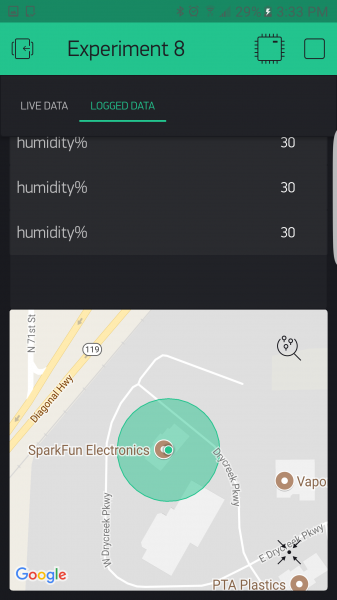
Troubleshooting
Blynk Shortcut!
If you are having troubles duplicating the functionality above in the Blynk app, scan this QR code with Blynk to get a clone of this experiment!
Experiment 9: Using a Current Sensor
Introduction
In Experiment 1 you gained ultimate control over being able to turn on and off appliances that plug into the wall through the use of the IoT Relay. But you didn’t have a way to determine if the appliance was on, off or even plugged in, let alone the ability to track how much current it was using. Well, that is all going to change with this experiment!
In this experiment you are going to learn about the Non-Invasive Current Sensor (NICS). The NICS clips around a single wire of an extension cord that is plugged into the power cord of any appliance and, with some basic wiring, will enable you to track the amount of current a given appliance is consuming at that moment without having to mess with exposed AC high-voltage wiring. You will be building a device that you can plug a device or appliance into to measure the number of watts that it uses. This is great for figuring out what appliances are using how much power, and later this circuit is a great way to detect if a device is on or off by way of monitoring how many watts it pulls.
Parts Needed
You will need the following parts:
- 1x Breadboard (From your Arduino 101 SIK)
- 1x Arduino 101 Board (From your Arduino 101 SIK)
- 1x TRRS Connector Breakout
- 1x Passive Current Sensor
- 1x 10 uF Capacitor
- 2x 10k Ohm Resistor (From your Arduino 101 SIK)
- 1x 100 Ohm Resistor (From your Arduino 101 SIK)
- 7x Jumper Wires (From your Arduino 101 SIK)
- 1x Air Conditioner Extension Cord, 3′ (Amazon)
Didn’t Get the Around-the-Home Expansion Kit?
If you are conducting this experiment and didn’t get the Around-the-Home Expansion Kit, we suggest using these parts:
Headers or No Headers?
Note:If you are buying the breakout boards (TRRS Breakout) seperate from this kit you will also need to buy female breakaway pins and assemble (solder) the pins to your board yourself.
You will also need an Arduino 101 board.
9
Retired
Suggested Reading
Before continuing with this experiment, we recommend you be familiar with the concepts in the following tutorials:
- Light-Emitting Diodes — Learn more about LEDs
- Switch Basics — Learn more about buttons and switches
Introducing the Current Sensor
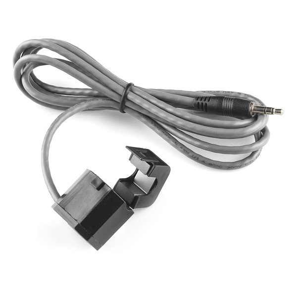
The Non-Invasive Current Sensor (NICS) has a «jaw» that clamps around a wire. It can read the amount of current flowing through the wire without the wire itself having to be modified (ergo, non-invasive). By an appliance into an extension cord and then using the current sensor to detect how much current is going through the extension cord, we’ll be able to tell when the AC is running.
The current sensor’s output is a current much lower than, but linearly related to, the current it’s sensing.
TRRS Breakout
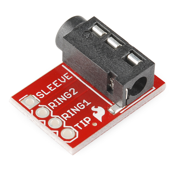
The NICS has a connector that looks like an audio jack on one end. It is a TRS (Tip-Ring-Sleeve) connector, shown on the left side of the diagram below. You may also have seen TRRS connectors (Tip-Ring-Ring-Sleeve, right side of diagram), which are commonly used for hands-free headsets. The TRRS breakout makes each of the pieces of a TRRS connector (the tip, each of the two rings and the sleeve) accessible. The TRRS breakout will allow us to easily connect to the tip and the sleeve of the current sensor’s connector so we can read its values.
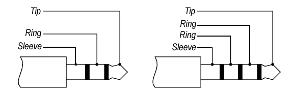
OK, now that we have figured out the new parts at the party, let’s build the circuit!
Hardware Hookup
Ready to start hooking everything up? Check out the wiring diagram below to see how everything is connected.
Wiring Diagram for the Experiment
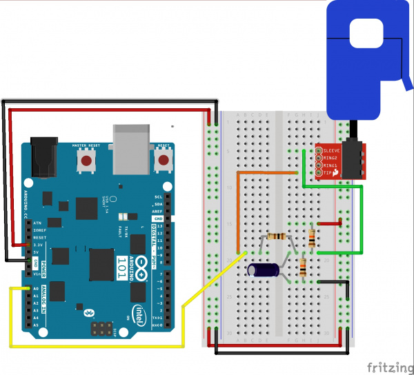
Having a hard time seeing the circuit? Click on the wiring diagram for a closer look.
To hook the current sensor up to the extension cord you’ll need a sharp utility knife and a safe, clean cutting surface. On your surface, lay the Air Conditioner Extension Cord flat, and use the utility knife to separate one of the three joined sections of wire. Make the cut approximately 3 to 4 inches long—just long enough to put the current sensor’s top «jaw» through and safely clip it together.
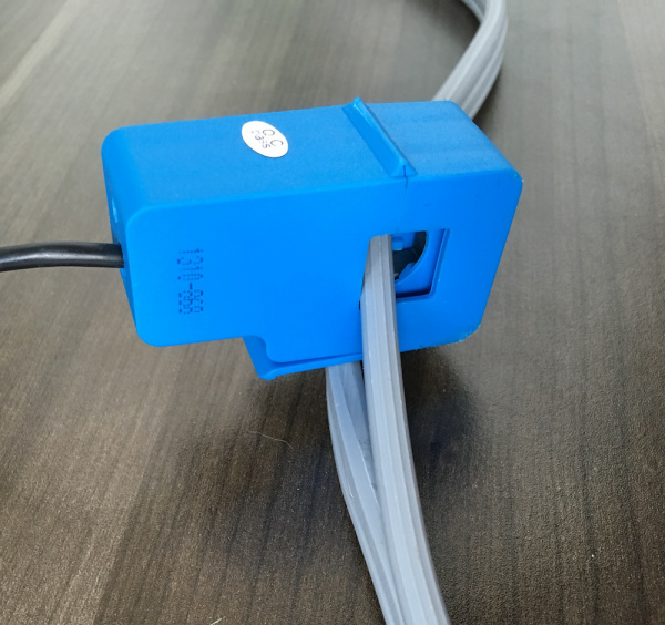
WARNING: If you expose ANY wire during this process, immediately discard the entire extension cord and start over with an uncut cord. We recommend purchasing two of these just in case. Exposed wire will put you at risk of fire or electrocution.
Build Your Blynk App
In creating this app you will build a gauge that will display the wattage of the device you are measuring in real time, as well as a graph of the time that your phone is connected to it. So, you can see where you are and where you have been (short term) — and watch the wattage use over the time that you are watching.
As with all of the Blynk apps that use the Arduino 101 board, add the BLE widget and open the settings to connect your phone to the Arduino 101. Once you have added the BLE widget, you can start to add the other widgets for this app. We start out by bringing the gauge widget into your app and opening the widget settings. This gauge will display the wattage draw from the NICS, which we will be writing to pin V0.
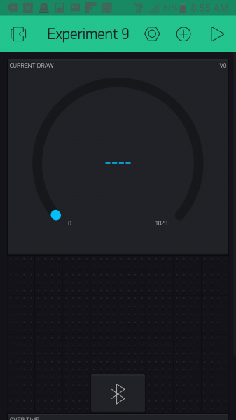
Open the settings of your gauge. Name your gauge (we labeled ours «Wattage») and set the pin to pin V0. For this we also changed the value range to 0—20, as we probably wouldn’t be pulling 1023 amps from an appliance. The last setting is the Label for the gauge, which we set as «Wattage: /pin/ Watts». We placed the gauge and resized it so that it is the dominant view of the app. With that we are done with the gauge.
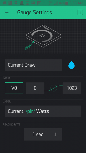
After adding the gauge, you can now add the graph widget and place it below the gauge as shown below.
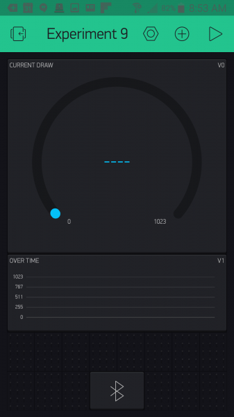
Now, open the graph widget settings. We named our graph «Over Time» as it will display the Wattage use over the time that you have the app opened. We set the pin to pin V1 as we cannot point two widgets at the same virtual pin at the same time; we will fix this in our sketch! In terms of the value range we changed the standard 0—1023 to 0—4000 since these values will be in watts and not a 10-bit (0—1023) number. After doing some extensive research (Google) we found that a dishwasher can consume around 3600 watts, so we aimed for a little higher than that. Finally, we changed the style to Line. With that we are done with the app!

Uploading Your Sketch
Open the Arduino IDE software on your computer. Coding in the Arduino language will control your circuit.
You can type out or copy and paste the following code into the Arduino IDE. Hit upload, and see what happens!
language:cpp
/********************************************************************************
SparkFun Around-The-Home SIK Expansion Kit, Experiment 9
SparkFun Electronics
Product URL

Build a device to measure the power useage of an applicance around your home and then display it in a Blynk app.

This example is written by: Derek Runberg, Educational Technologist

This sketch was written by SparkFun Electronics, with lots of help from the Arduino community.
This code is completely free for any use.

View circuit diagram and instructions at:https://learn.sparkfun.com/tutorials/around-the-home-expansion-kit

********************************************************************************/

/* Comment this out to disable prints and save space */
#define BLYNK_PRINT Serial
#include <BlynkSimpleCurieBLE.h>
#include <CurieBLE.h>
#include <math.h>

BLEPeripheral  blePeripheral;


// You should get Auth Token in the Blynk App.
// Go to the Project Settings (nut icon).
char auth[] = "YOUR_AUTH_TOKEN";


const int CURRENT_SENSOR_PIN = A1;
const int LED_PIN = 13;

int  currentWatts;
int calibratedWattage;

void setup()
{
  blePeripheral.setLocalName("Exp_09");
  blePeripheral.setDeviceName("Exp_09");
  blePeripheral.setAppearance(384);

  Blynk.begin(blePeripheral, auth);
  blePeripheral.begin();

  Serial.begin(9600);

// Setup notification button on pin 2  pinMode(REPLAY_PIN, OUTPUT);
  calibratedWattage = getWatts(CURRENT_SENSOR_PIN);
}

void loop()
{
  currentWatts = getWatts(CURRENT_SENSOR_PIN);
  Serial.println(currentWatts);

  if(currentWatts > calibratedWattage){
    digitalWrite(LED_PIN, HIGH);
  }
  else{
    digitalWrite(LED_PIN, LOW);
  }
  blePeripheral.poll();
  Blynk.run();
}

float getWatts(int pin) {

  // RMS voltage
  const double vRMS = 120.0;      // Assumed or measured

  // Parameters for measuring RMS current
  const double offset = 1.65;     // Half the ADC max voltage
  const int numTurns = 2000;      // 1:2000 transformer turns
  const int rBurden = 100;        // Burden resistor value
  const int numSamples = 1000;    // Number of samples before calculating RMS

  int sample;
  double voltage;
  double iPrimary;
  double acc = 0;
  double iRMS;
  double apparentPower;

  // Take a number of samples and calculate RMS current
  for ( int i = 0; i < numSamples; i++ ) {

  // Read ADC, convert to voltage, remove offset
  sample = analogRead(pin);
  voltage = (sample * 3.3) / 1023;
  voltage = voltage - offset;

  // Calculate the sensed current
  iPrimary = (voltage / rBurden) * numTurns;

  // Square current and add to accumulator
  acc += pow(iPrimary, 2);
  }

  // Calculate RMS from accumulated values
  iRMS = sqrt(acc / numSamples);

  // Calculate apparent power and return it
  apparentPower = vRMS * iRMS;
  return apparentPower;
}

//write the real time current draw of the fan when read from the app
BLYNK_READ(V0) {
  //read current sensor

  Blynk.virtualWrite(0, currentWatts);
}

BLYNK_READ(V1) {
  Blynk.virtualWrite(1, currentWatts);
}
Code to Note
This sketch is by far the heaviest sketch in terms of programming. The good thing is that most of it is collecting readings and calculating equations. We wrapped all of the complicated math into the getWatts() function to give you the option of taking a closer look at how we did it and changing it for your own situation…or just using it out of the box!
language:cpp
int  currentWatts;
int calibratedWattage;
We started out by creating two global variables: one stores the current watts calculated by the Arduino 101 board later in the sketch, and the other stores a calibration value, which is just a single wattage reading in the setup() — that way we have a starting point to compare to.
calibratedWattage = getWatts(A0);
To get a calibration value we just call the getWatts(A0) function in setup() and store it in the callibrationWattage variable. This only happens once at power-up, so if you want to recalibrate you can use the RESET button on the Arduino 101 board, or power cycle the board.
language:cpp
// RMS voltage
const double vRMS = 120.0;      // Assumed or measured
const double offset = 1.65;     // Half the ADC max voltage
const int numTurns = 2000;      // 1:2000 transformer turns
const int rBurden = 100;        // Burden resistor value
const int numSamples = 1000;    // Number of samples before calculating RMS
Inside of the getWatts() function there are a number of variables that are used to calculate the wattage output of the function and using the NICS. A couple of them that you will need to manipulate depending on your use are:
const double vRMS = 120.0;— If you are in Europe or measuring an outlet that is higher voltage, you will need to change this.const double offset = 1.65;— If you are using a 5-volt board, this value should be 2.5.
language:cpp
// Take a number of samples and calculate RMS current
for ( int i = 0; i < numSamples; i++ ) {
// Read ADC, convert to voltage, remove offset
sample = analogRead(pin);
voltage = (sample * 3.3) / 1023;
voltage = voltage - offset;
// Calculate the sensed current
iPrimary = (voltage / rBurden) * numTurns;
// Square current and add to accumulator
acc += pow(iPrimary, 2);
}
// Calculate RMS from accumulated values
  iRMS = sqrt(acc / numSamples);
// Calculate apparent power and return it
apparentPower = vRMS * iRMS;
return apparentPower;
Here are the full calculations from taking the 10-bit analog value from reading pin A0 to calculating the voltage and so on. The comments in the code lead you through the full process. The main thing to note here is that when all is said and done, the function returns a float value using return apparentPower;
currentWatts = getWatts(A0);
In the loop we update the currentWatts variable using the getWatts() function.
language:cpp
BLYNK_READ(V0) {
  Blynk.virtualWrite(0, currentWatts);
}

BLYNK_READ(V1) {
  Blynk.virtualWrite(1, currentWatts);
}
Finally, we respond to the BYLNK_READ() event functions with the same response with a single change of what pin we write to since we cannot point both widgets at the single event…bummer!
Troubleshooting
Blynk Shortcut!
If you are having troubles duplicating the functionality above in the Blynk app, scan this QR code with Blynk to get a clone of this experiment!

Odd Numbers?
Make sure that you have hooked up the circuit correctly, especially the capacitors! Capacitors are highly polarized.
Still odd!
make sure the connection of the RTTS connector is fully inside of the breakout connector and that the sensor itself is correctly fastened around the wire to be read.