Samsung и Cookies
На этом сайте используются файлы cookie. Нажимая ПРИНЯТЬ или продолжая просмотр сайта, вы разрешаете их использование.
Подробнее
В настоящий момент товары недоступны для заказа на samsung.com/ru
В настоящий момент товары недоступны для заказа на samsung.com/ru
Выберите свое местоположение и язык.
УЗИ сканер SonoAce-X6 (Samsung Medison, снят с производства)
SonoAce X6 — многофункциональный ультразвуковой сканер компании Samsung Medison с оптимальным набором функций и всеми видами чувствительного допплера. Аппарат позволяет проводить обследование большого потока пациентов — рекомендуется для применения в медицинских центрах, женских консультациях, больницах и поликлиниках.
Области применения: акушерство и гинекология, абдоминальные исследования и маммология, урология и эхокардиография, поверхностно расположенные органы и исследования сосудов, мускуло-скелетные исследования, а также педиатрия.
Базовая комплектация: сканер SonoAce X6 (монитор 15″; допплеры: цветной, энергетический, импульсный (в том числе HPRF), 2-я гармоника, SonoView-II Pro (архивация изображения и кинопетли); кинопамять; встроенный дисковод DVD-RW; 4 USB-порта, встроенная клавиатура с трекболом, флакон геля 250 мл и руководство оператора).
Опции для сканера SonoAce X6: кардиопакет: тканевый допплер (TDI) + цветной М-режим (CM) + программное обеспечение; непрерывноволновой допплер (CW); ЭКГ модуль; устройства хранения информации (USB флеш-карта, USB флеш-диск); система DICOM.
- Стационарный ультразвуковой сканер.
- LCD монитор — 15″ (36 см).
- Кардиопакет (опция).
- ЭКГ модуль (опция).
- Режимы сканирования: B, 2B, M, B+M, 4B;
— CFM — цветное допплеровское картирование;
— PD — энергетический допплер;
— направленный энергетический допплер;
— PW — импульсный допплер;
— HPRF — высокочастотный импульсный допплер;
— CW — непрерывноволновой допплер. - Особенности сканирования:
— тканевая гармоника (регистрация 2-й гармоники эхосигнала, в том числе с помощью инверсивной технологии, опция, входит в кардиопакет);
— цветной М-режим (опция, входит в кардиопакет);
— тканевый допплер — тканевая цветовая допплерография для оценки сократительной способности миокарда (опция, входит в кардиопакет);
— автоматический анализ допплеровских кривых;
— глубина сканирования до 30 см;
— steering — возможность изменения допплеровского угла в режимах CFM и PD;
— дуплексный и триплексный режим. - Разьемы для одновременного подключения до 4-х датчиков (3 + 1 CW).
- Система DICOM (опция) — возможность сетевой интеграции с PACS-системами (например, для архивации или печати ультразвуковых эхограмм на оборудовании других производителей медтехники).
Инновационные технологии
- FSI (Full Spectrum Imaging) — комбинирует ультразвуковую информацию от акустических полос разной частоты, снижая количество артефактов. Эффективное использование всех частот датчика обеспечивает также превосходное качество изображения с плотной контрастностью независимо от глубины проникновения.
- THI (Tissue Harmonic Imaging, тканевая или 2-я гармоника) — улучшает качество изображения, линейное и контрастное разрешение у пациентов с повышенным весом.
- Pulse Inversion Harmonic (тканевая инверсная гармоника) — применяется при исследовании движущихся тканей (сосуды, сердце) и трудновизуализируемых тканей (с похожей акустической плотностью), таких как опухоли.
- Трапецевидный режим — простым нажатием кнопки изображение от обычного линейного датчика расширяется, предоставляя почти на 20% больше клинической информации. Этот режим отлично подходит для исследования поверхностных органов.
- SRF (Speckle Reduction Filter) — фильтр подавления мерцающих помех.
- FINE — повышение контрастности контуров и уменьшение уровня шумов.
- CAFE Plus — улучшает визуализацию кровотока в допплеровских режимах.
- OSIO — органоспецифическая оптимизация изображения.
- Quick Scan — ускоренный режим (нажатием одной кнопки) настройки изображения исследуемого органа в B- и D-режиме (настройка оптимальных параметров и фильтров за счет автоматического распознавания исследуемого органа по интеллектуальной базе данных человеческих органов).
Пакеты ультразвуковых диагностических программ
- Полностью русифицированное программное обеспечение.
- Основные измерения: измерения расстояния, окружности, площади, объема; измерение тазобедренного сустава; измерение расстояния в M-режиме; измерение скорости в спектральном допплеровском режиме и др.
- Пакет гинекологических исследований: матка, левый и правый яичники, левая и правая почки, артерии левого и правого яичников, левый и правый фолликулы.
- Пакет акушерских исследований: биометрия плода, краниологическое исследование плода, исследование длинных костей плода, измерение индекса околоплодных вод (AFI), допплер плода и др. Биометрия плода включает измерения теменно-копчиковой длинны (CRL), размера плодного пузыря (GS), бипариетальный размера головки плода (BPD), затылочно-лобного расстояния (OFD), длины окружности головы плода (НC), передне-заднего размера брюшной полости (APD), поперечного размера брюшной полости (TAD), окружности живота (AC), площади сечения тела (FTA), длины бедра (FL), поперечного (TTD) и передне-заднего (APTD) размеров тела плода. Краниологическое исследование плода включает измерения параметров мозжечка (CEREB), а также внешнего (OOD) и внутреннего (IOD) межглазных расстояний. Исследование длинных костей плода включает измерения длины плечевой кости (Humerus), локтевой кости (Ulna), большеберцовой кости (Tibia), лучевой кости (Rad), ключицы (Clav) и позвоночника (LV).
Кроме того, семь уравнений для оценки веса плода: Хедлок (Hadlock) 1-4, Хансман (Hansmann) и Мерц (Merz); ЧСС плода (Fetal HR); таблицы, определяемые пользователем. - Пакет урологических расчетов: разностный объем, объем предстательной железы, вычисление плотности простатспецифического антигена (PSA).
- Пакет кардиологических исследований:
— в 2D-режиме рассчитываются значения таких параметров, как объем по методу Симпсона (Simpson), объем по площади и длине, двумерные характериcтики (например, фракция выброса левого желудочка) и масса левого желудочка;
— в M-режиме вычисляются значения параметров для левого желудочка, аорты и левого предсердия, митрального клапана, а также частота сердечных сокращений.
— специальный пакет программ для исследования сердечно-сосудистой системы плода (расчет сократительной способности миокарда, оценка клапанного аппарата, магистральных артерий и вен). - Пакет расчетов параметров сосудов: вычисления объемного кровотока, процента стеноза, индекса сопротивления (RI), пульсационного индекса (PI) и др.
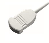
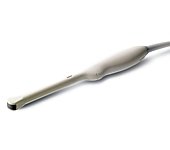
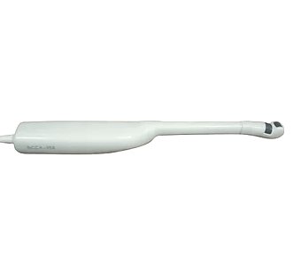
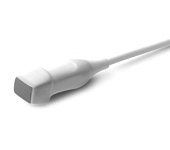
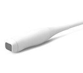
Датчики для сканера SonoAce X6
Конвексные датчики
Конвексный датчик 2-5 МГц
Акушерские исследования (плод, сердце плода), гинекология (матка, яичники), абдоминальные исследования (печень, желчный пузырь, поджелудочная железа, селезенка, глубокие сосуды), почки.
Биопсийный набор: есть.
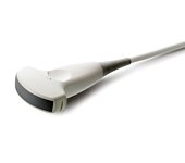
Конвексный датчик 2-8 МГц
Акушерские исследования (плод, сердце плода), гинекология (матка, яичники), абдоминальные исследования (печень, желчный пузырь, поджелудочная железа, селезенка, глубокие сосуды), почки.
Биопсийный набор: есть.
Конвексный датчик 4-9 МГц (вагинальный)
Акушерские исследования (ранние сроки), гинекология (матка, яичники).
Биопсийный набор: есть.
Конвексный датчик 4-9 МГц (неонатальный)
Неонатология и педиатрия: абдоминальные исследования, почки, сердце, глубокие сосуды, мозг.
Биопсийный набор: нет.
Конвексный датчик 4-9 МГц (ректо-вагинальный)
Акушерские исследования (ранние сроки), гинекология (матка, яичники), урология (предстательная железа), исследования прямой кишки.
Биопсийный набор: есть.
Биплановые датчики
Биплановый внутриполостной датчик 4-9 МГц
Исследование предстательной железы.
Биопсийный набор: есть.
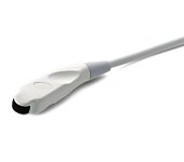
Фазированные датчики
Фазированный датчик 2-4 МГц
Кардиология и транскраниальные исследования у взрослых.
Биопсийный набор: нет.
Фазированный датчик 3-7 МГц
Кардиология и транскраниальные исследования у детей.
Биопсийный набор: нет.
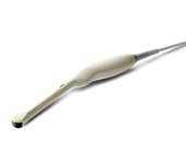
Линейные датчики
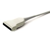
Линейный датчик 5-12 МГц / 40 мм
Поверхностные структуры (щитовидная железа, молочная железа, лимфоузлы), мускулоскелетные исследования (суставы, мышцы, подкожные структуры), периферические сосуды.
Биопсийный набор: есть.
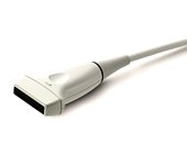
Линейный датчик 5-12 МГц /50 мм
Поверхностные структуры (щитовидная железа, молочная железа, лимфоузлы), мускулоскелетные исследования (суставы, мышцы, подкожные структуры), периферические сосуды.
Биопсийный набор: есть.
Допплеровские датчики
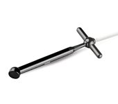
Допплеровский датчик 2.0 (слепой допплер)
Транскраниальные исследования, сосуды.
Биопсийный набор: нет.
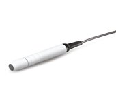
Допплеровский датчик 4.0 (слепой допплер)
Транскраниальные исследования, сосуды.
Биопсийный набор: нет.
Внимание! Копирование или частичная перепечатка материалов проспекта сканера «SonoAce X6» на русском языке и размещение в интернет без согласия владельца (ЗАО «Медиэйс») запрещена, запрос на копирование материала можно отправить здесь.
Руководства Samsung SONOACE X6 Размер файлов: 6167 KB, Язык: English, Формат: pdf, Платформа: Windows/Linux, Дата: 2017-04-06
На данной странице вы можете скачать руководства Samsung SONOACE X6. Мы предлагаем вам ознакомиться с руководством пользователя, инструкцией по сервисному обслуживанию и ремонту.
Также здесь вы найдете список заказных номеров на комплектующие Samsung SONOACE X6.
Все файлы предоставляются исключительно в ознакомительных целях. И не являютя руководством по ремонту, а направлены лишь на то чтобы помочь вам более детально ознакомиться с принципом построения устройства.
Содержимое представленных здесь руководств требуют от вас знания технического английского языка.
Если вы собираетесь скачать руководство по сервисному обслуживанию Samsung SONOACE X6, иными словами сервис мануал, вы дожны обладать хотя бы минимальными познаниями в области электроники и пониманием базовых принципов работы электромеханических устройств.
Для просмотра руководств вам понадобится Adobe Acrobat Reader версии 9 и выше либо другая программа для просмотра pdf файлов.
В связи с популярностью информации представленной на сайте и ее бесплатного предоставления конечному пользователю, убедительная просьба использовать специальные программные продукты для многопотокового скачивания файлов.
Руководства для Samsung SONOACE X6
- Руководство пользователя (User manual)
- Руководство по сервисному обслуживанию (Service manual)
- Руководство по ремонту (Repair manual)
- Перечень комплектующих (PartList)
SONOACE X6 Service Manual
ENGLISH
Document No. CSD-SMEX6
Revision 00
Copyright 2008 by MEDISON

Safety Requirements
Classifications:
—Type of protection against electrical shock: Class I
—Degree of protection against electrical shock (Patient connection):Type BF equipment
—Degree of protection against harmful ingress of water: Ordinary equipment
—Degree of safety of application in the presence of a flammable anesthetic material with air or with oxygen or nitrous oxide: Equipment not suitable for use in the presence of a flammable anesthetic mixture with air or with oxygen or nitrous oxide.
—Mode of operation: Continuous operation
Electromechanical safety standards met:
—IEC/EN 60601-1 Medical Electrical Eqiupment, Part 1General Requirements for Safety.
—IEC/EN 60601-1-1 Safety requirements for medicalelectrical systems.
—IEC/EN 60601-1-2 Electromagnetic compatibility -Requirements and tests.
—IEC/EN 60601-2-37 Particular requirements for the safety of ultrasonic medical diagnostic and monitoring equipment.
—IEC 61157 Declaration of acoustic output parameters.
—ISO 10993-1 Biological evaluation of medical devices.
—UL 2601-1 Medical Electrical Equipment, Part 1 General Requirements for Safety.
—CSA 22.2, 601.1 Medical Electrical Equipment, Part 1 General Requirements for Safety.

Declarations;
 0123
0123
This is CSA symbol for Canada and United States of America
This is manufacturer’s declaration of product compliance with applicable EEC directive(s) and the European notified body.
This is manufacturer’s declaration of product compliance with applicable EEC directive(s).

READ THIS FIRST
Before asking for the product to be repaired, read this service manual thoroughly, learn how to troubleshoot, and make sure you understand the precautions fully.
The repair of the system and the replacement of parts must be carried out by an authorized dealer or the customer care department of MEDISON Co., Ltd.
Thecompanyshallnotbeheld liablefor any injuryanddamagecausedby notfollowing this warning.
For safe use of this product, you should read ‘Chapter 2. Safety’ in this manual, prior to starting
to useing this system.
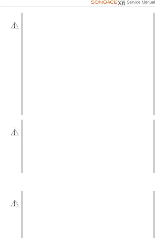
DANGER
WARNING
CAUTION
NOTE
Describes precautions necessary to prevent user hazards of great urgency. Ignoring a DANGER warning will risk life-threatening injury.
Used to indicate the presence of a hazard that can cause serious personal injury, or substantial property damage.
Indicates the presence of a hazard that can cause equipment damage.
A piece of information useful for installing, operating and maintaining a system. Not related to any hazard.

««`Contents
|
Chapter 1. |
General Information |
1-1 |
|
|
1.1 |
Overview |
1-1 |
|
|
1.2 |
Features and Advantages of SONOACE X6 |
1-2 |
|
|
1.3 |
Product Configuration |
1-3 |
|
|
1.3.1 |
Console |
1-3 |
|
|
1.3.2 |
LCD Monitor |
1-5 |
|
|
1.3.3 |
Control Panel |
1-6 |
|
|
1.3.4 |
Probe |
1-7 |
|
|
1.4 |
Specifications |
1-8 |
|
|
Chapter 2. |
Safety |
2-1 |
|
|
2.1 |
Overview |
2-1 |
|
|
2.2 |
Safety – Related Information |
2-2 |
|
|
2.2.1 |
Safety Symbols |
2-2 |
|
|
2.2.2 |
Label |
2-4 |
|
|
2.3 |
Electrical Safety |
2-6 |
|
|
2.3.1 |
Prevention Electric Shock |
2-6 |
|
|
2.3.2 |
ECG — Related Information |
2-7 |
|
|
2.3.3 |
ESD |
2-8 |
|
|
2.3.4 |
EMI |
2-8 |
|
|
2.3.5 |
EMC |
2-9 |
|
|
2.4 |
Mechanical Safety |
2-15 |
|
|
2.4.1 |
Moving the Equipment |
2-15 |
|
|
2.4.2 |
Safety Note |
2-16 |
|
|
2.5 |
Biological Safety |
2-17 |
|
|
2.5.1 |
ALARA Principle |
2-17 |
|
|
2.6 |
Environmental Protection |
2-29 |
Contents

Contents
|
Chapter 3. Installing the Product |
3-1 |
||
|
3.1 |
Overview |
3-1 |
|
|
3.2 |
Transportation |
3-3 |
|
|
3.2.1 |
Precautions for Transportation |
3-3 |
|
|
3.2.2 |
Temperature and Humidity |
3-3 |
|
|
3.2.3 Transportation of the Product |
3-4 |
||
|
3.3 |
Unpacking |
3-5 |
|
|
3.3.1 |
Unpacking the Box |
3-5 |
|
|
3.3.2 |
Checking Package Contents |
3-6 |
|
|
3.4 |
Precautions for Installation |
3-7 |
|
|
3.4.1 |
Precautions |
3-7 |
|
|
3.4.2 |
Installation Location |
3-8 |
|
|
3.5 |
Installation Procedure |
3-9 |
|
|
3.5.1 |
Installation Safety |
3-9 |
|
|
3.5.2 Connecting the Power Cord |
3-10 |
||
|
3.5.3 Connecting the Network Cable |
3-11 |
||
|
3.5.4 Connecting the Foot switch |
3-11 |
||
|
3.5.5 |
Connecting the Probe |
3-12 |
|
|
3.6 |
Starting the Product |
3-13 |
|
|
3.7 |
Shutting down the Product |
3-15 |
|
|
3.7.1 |
Power Switch |
3-15 |
|
|
3.7.2 |
Cut-off Switch |
3-15 |
|
|
3.8 |
Connecting the Peripherals |
3-16 |
|
|
3.8.1 |
BW Printer |
3-16 |
|
|
3.8.2 |
Color Printer |
3-17 |
|
|
3.8.3 |
Line Printer |
3-18 |
|
|
3.8.4 |
VCR |
3-18 |
|
|
3.8.5 |
USB Storage Device |
3-19 |
|
|
3.9 |
System Setting |
3-20 |
|
|
3.9.1 |
General System Setup |
3-20 |
|
|
3.9.2 |
Display Setup |
3-22 |
|
|
3.9.3 |
Misc |
3-24 |
|
|
3.9.4 |
Peripherals Setup |
3-25 |
|
|
3.9.5 |
Information |
3-26 |
|
|
3.9.6 |
DICOM Setup (Option) |
3-27 |
|
|
3.9.7 |
Option Setup |
3-34 |
Contents
Contents
|
Chapter 4. Checking the Product |
4-1 |
||
|
4.1 |
Overview |
4-1 |
|
|
4.2 |
Starting the Product |
4-2 |
|
|
4.3 |
Monitor |
4-6 |
|
|
4.3.1 |
Monitor Display |
4-4 |
|
|
4.4 |
Control Panel |
4-6 |
|
|
4.4.1 |
Power On/Off |
4-6 |
|
|
4.4.2 |
Starting and Finishing Exam |
4-6 |
|
|
4.4.3 |
Selecting Diagnosis mode and Gain Control |
4-7 |
|
|
4.4.4 |
Image Adjustment |
4-9 |
|
|
4.4.5 |
TGC |
4-10 |
|
|
4.4.6 |
Measurement and Annotation |
4-10 |
|
|
4.4.7 |
Trackball and its related control |
4-11 |
|
|
4.4.8 |
SONOVIEW and Report |
4-12 |
|
|
4.4.9 |
Save and Print |
4-12 |
|
|
4.4.10 |
Alphanumeric keyboard |
4-13 |
|
|
4.4.11 |
Flexible Soft Buttons |
4-13 |
|
|
4.4.12 |
Function Buttons |
4-14 |
|
|
4.5 |
Checking the Performance |
4-15 |
|
|
4.5.1 |
Basic Check |
4-15 |
|
|
4.5.2 |
Detail Check |
4-16 |
Contents

Contents
|
Chapter 5. |
Product Structure |
5-1 |
|
|
5.1 |
Overview |
5-1 |
|
|
5.2 |
System Block Diagram |
5-3 |
|
|
5.3 |
Basic Structure of SONOACE X6 |
5-4 |
|
|
5.3.1 |
Overview |
5-4 |
|
|
5.3.2 |
Ultrasound System Part |
5-5 |
|
|
5.3.3 |
User Interface Part |
5-5 |
|
|
5.3.4 |
Power Part |
5-5 |
|
|
5.4 |
PSA |
5-6 |
|
|
5.5 |
Front End Board |
5-9 |
|
|
5.6 |
CW Board |
5-13 |
|
|
5.7 |
Back End Board |
5-15 |
|
|
5.8 |
Rear Board |
5-22 |
|
|
5.9 |
Control Panel |
5-23 |
|
|
5.10 Power Supply |
5-24 |
||
|
Chapter 6. |
Basic Maintenance |
6-1 |
|
|
6.1 |
Overview |
6-1 |
|
|
6.2 |
System Information |
6-2 |
|
|
6.3 |
Entering Admin Mode |
6-3 |
|
|
6.4 |
Upgrade |
6-6 |
|
|
6.4.1 |
Software Upgrade |
6-6 |
|
|
6.4.2 |
Hardware Upgrade |
6-9 |
|
|
6.5 |
Backup & Restore |
6-10 |
|
|
6.5.1 |
Backup User Setting |
6-10 |
|
|
6.5.2 |
Restore User Setting |
6-11 |
|
|
6.6 Adding and Deleting Options |
6-13 |
||
|
6.6.1 |
Option type |
6-13 |
|
|
6.6.2 |
Registering Options |
6-13 |
|
|
6.6.3 |
Deleting Options |
6-14 |
|
|
6.7 |
Control Panel Test |
6-15 |
Contents
Contents
|
Chapter 7. |
Troubleshooting |
7-1 |
|
|
7.1 |
Overview |
7-1 |
|
|
7.2 |
Power |
7-2 |
|
|
7.2.1 |
Power Failure |
7-2 |
|
|
7.2.2 Power cannot be turned off |
7-2 |
||
|
7.2.3 Power is automatically turned off |
7-3 |
||
|
7.3 |
Monitor |
7-4 |
|
|
7.3.1 |
Blank Screen |
7-4 |
|
|
7.3.2 Screen Color is Abnormal |
7-4 |
||
|
7.4 |
Error Messages |
7-5 |
|
|
7.4.1 System hangs after an error during booting |
7-5 |
||
|
7.4.2 System works even if error occurred |
7-5 |
||
|
7.4.3 |
Error code |
7-5 |
|
|
7.5 |
Image |
7-6 |
|
|
7.5.1 No BW Image Echo |
7-6 |
||
|
7.5.2 No BW Mode Image Format |
7-6 |
||
|
7.5.3 Noise Link Rain over the BW Mode Image (Noise) |
7-6 |
||
|
7.5.4 PW Doppler Mode Trouble |
7-7 |
||
|
7.5.5 CW Doppler Mode Trouble |
7-7 |
||
|
7.5.6 Color Doppler Mode Trouble |
7-7 |
||
|
7.5.7 |
Motion Mode Trouble |
7-7 |
Contents

Contents
|
Chapter 8. Disassembly and Reassembly |
8-1 |
||
|
8.1 |
Overview |
8-1 |
|
|
8.2 |
Disassembly and Reassembly of the External Case |
8-4 |
|
|
8.2.1 |
Preparations |
8-4 |
|
|
8.2.2 |
Cover Front Lower |
8-4 |
|
|
8.2.3 |
Cover Top Plate |
8-5 |
|
|
8.2.4 |
Cover Rear Lower |
8-6 |
|
|
8.3 |
Disassembly and Reassembly of the LCD Monitor |
8-7 |
|
|
8.3.1 |
Preparations |
8-7 |
|
|
8.3.2 |
LCD Monitor |
8-7 |
|
|
8.3.3 |
LCD Monitor Arm |
8-8 |
|
|
8.4 |
Disassembly and Reassembly of the Ultrasound System PCB Part |
8-9 |
|
|
8.4.1 |
Preparations |
8-9 |
|
|
8.4.2 |
PSA ASSY |
8-9 |
|
|
8.4.3 CW Board, FE Board, BE Board |
8-10 |
||
|
8.4.4 DC to DC Power Module |
8-11 |
||
|
8.5 |
Disassembly and Reassembly of the HDD & DVD |
8-12 |
|
|
8.5.1 |
Preparations |
8-12 |
|
|
8.5.2 |
HDD & DVD |
8-12 |
|
|
8.6 |
Disassembly and Reassembly of the Rear Panel |
8-13 |
|
|
8.6.1 |
Preparations |
8-13 |
|
|
8.6.2 Rear Right Board & Rear Left Board |
8-13 |
||
|
8.6.3 |
Back Fan |
8-14 |
|
|
8.7 |
Disassembly and Reassembly of the Power Supply |
8-16 |
|
|
8.7.1 |
Preparations |
8-16 |
|
|
8.7.2 AC to DC Power Module |
8-16 |
||
|
8.7.3 DC to DC Power Module |
8-16 |
||
|
8.8 |
Disassembly and Reassembly of the Control Panel |
8-17 |
|
|
8.8.1 |
Preparations |
8-17 |
|
|
8.8.2 |
Control Panel |
8-17 |
|
|
8.8.3 |
Key Matrix Board |
8-18 |
|
|
8.8.4 |
Track Ball |
8-19 |
|
|
8.8.5 |
Alpha Numeric Keyboard |
8-20 |
|
|
8.8.6 |
Speaker |
8-20 |
Contents
![]()
Content
|
Chapter 9. |
Probe |
9-1 |
|
|
9.1 |
Overview |
9-1 |
|
|
9.2 |
Probe List |
9-2 |
|
|
9.3 |
Thermal Index (TI Table) |
9-3 |
|
|
9.4 |
Ultrasound Transmission Gel |
9-4 |
|
|
9.5 |
Sheaths |
9-5 |
|
|
9.6 |
Probe Precautions |
9-5 |
|
|
9.7 |
Cleaning and Disinfecting the Probe |
9-8 |
|
|
Chapter 10. |
User Maintenance |
10-1 |
|
|
10.1 |
Overview |
10-1 |
|
|
10.2 |
System Maintenance |
10-2 |
|
|
10.2.1 |
Installation Maintenance |
10-2 |
|
|
10.2.2 |
Cleaning and Disinfections |
10-3 |
|
|
10.2.3 Fuse Replacement |
10-5 |
||
|
10.2.4 Cleaning the Air Filter |
10-6 |
||
|
10.2.5 Accuracy Check |
10-6 |
||
|
10.3 |
Administration of Information |
10-7 |
|
|
10.3.1 User Setting Back-up |
10-7 |
||
|
10.3.2 |
Patient Information Back-up |
10-7 |
|
|
10.3.3 Software |
10-7 |
||
|
Chapter 11. ServicePart List |
11-1 |
||
|
11.1 |
Overview |
11-1 |
|
|
11.2 |
Cover |
11-2 |
|
|
11.3 |
Ultrasound System Part |
11-4 |
|
|
11.4 |
Rear Plan |
11-5 |
|
|
11.5 |
Power Part |
11-6 |
|
|
11.6 |
LCD Monitor |
11-7 |
|
|
11.7 |
Control Panel |
11-9 |
|
|
11.8 |
Probe |
11-10 |
Contents
1General Information
1.1Overview
Chapter1containstheinformationnecessarytoplantheTroubleshootingofSONOACEX6
TheSONOACE X6 isahigh-resolutioncolor ultrasoundsystemwith high penetration andavarietyofmeasurement functions
Contents General Information
|
1.1 |
Overview |
1-1 |
|
|
1.2 |
Features and Advantages of SONOACE X6 |
1-2 |
|
|
1.3 |
Product Configuration |
1-3 |
|
|
1.3.1 |
Console |
1-3 |
|
|
1.3.2 |
LCD Monitor |
1-5 |
|
|
1.3.3 |
Control Panel |
1-6 |
|
|
1.3.4 |
Probes |
1-7 |
|
|
1.4 |
Specifications |
1-8 |
Chapter 1. General Information 1-1

1.2Features and Advantages of SONOACE X6
|
y |
High-endDigitalBeamforming:The SONOACEX6utilizesthenewly developed |
|
DigitalBeam formingtechnology. |
|
|
y |
A variety of applications : The SONOACE X6 is optimized for use in a variety of |
|
ultrasound departments, including general, abdomen, obstetrics, gynecology, |
|
|
vascular, extremity, pediatric, cardiac, breast, urology, and etc. |
yVarious diagnostic Modes : 2D Mode, M Mode, Color Doppler Mode, Power Doppler Mode, PW Spectral Doppler Mode, CW Spectral Doppler Mode(Option), etc.
y3D images can be obtained.
yMeasurement and Report Functions : Besides the basic distance, area,
circumference and volume measurement functions, the SONOACE X6 also provides application-specific measurement functions. The report function collates measurement data.
y Review of Scanned Images : The SONOACE X6 displays Cine images of 512 frames and loop images of 4096 lines.
ySonoViewTM : This is a total ultrasound image management system, which allows a user to archive, view and exchange documents.
yDigital Imaging and Communications in Medicine (DICOM) Function : This is used to archive, transmit and print DICOM images through a network.
yPeripheral/Accessory Connection : A variety of peripheral devices including VCRs and printers can be easily connected to the SONOACE X6.
Chapter 1. General Information 1-2
1.3Product Configuration
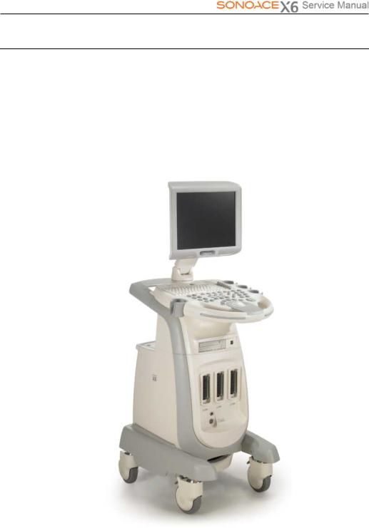
This Product consists of the monitor, the control panel, the console and the probes.
1.3.1Console
Theconsoleconsistsoftwoparts–the inner unitandtheouterunit.
Theinterioroftheconsolemainlycontainsdevicesthat produceultrasoundimages. Ontheexterioroftheconsole iscomposed ofvariousconnectors, probeholders, storagecompartments,handles,wheels,etc.
 LCD Monitor
LCD Arm 
 Control Panel
DVD-RW Drive 
 Probe Connector
Pencil probe Connector 
 Wheel
Wheel
[Figure 1-1] Console of SONOACE X6
Chapter 1. General Information 1-3
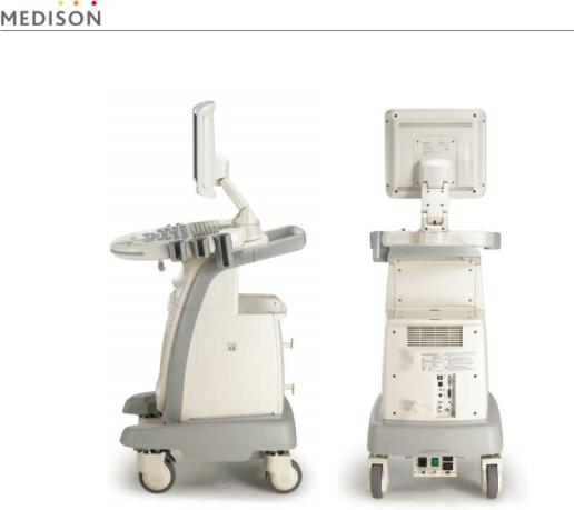
[Figure 1-2] Rear and side of SONOACE X6
Chapter 1. General Information 1-4
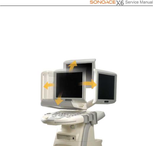
1.3.2LCDMonitor
The LCD monitor of this system is a color VGA monitor, which displays ultrasound images and additional information. Use the monitor arm to adjust the height or position of the monitor.
[Figure 1-3] LCD Arm
Chapter 1. General Information 1-5
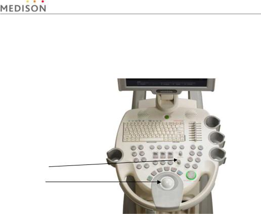
1.3.3Control Panel
The control panel can be used for controlling the system. It consists of the following four sections:
Alphanumerics Keyboard 
Slide Volume 
Button 
Dial Button
Track Ball
[Figure 1-4] Control Panel
Chapter 1. General Information 1-6

1.3.4Probe
Probes are devices that generate ultrasound waves and process reflected wave data for the purpose of image formation.
NOTE For more information, refer to `Chapter 9 Probes’.
Chapter 1. General Information 1-7

1.4Specifications
|
Height: 1378mm (with monitor) |
|||||
|
Physical Dimensions |
Width: 483mm |
||||
|
Depth: 691mm |
|||||
|
Weight: More than 60.75kg |
|||||
|
Monitor |
15 inch LCD monitor |
||||
|
Electrical Parameters |
100-120V/200-240VAC, 8/5A, 50/60Hz |
||||
|
Pressure Limits |
Operating: 700hPa to 1060hPa |
||||
|
Storage: 700hPa to 1060hPa |
|||||
|
Humidity Limits |
Operating: 30% to 75% |
||||
|
Storage & Shipping: 20% to 90% |
|||||
|
Temperature Limits |
Operating: 10OC ~ 35OC |
||||
|
Storage & Shipping: -25OC ~ 60OC |
|||||
|
2D imaging mode |
|||||
|
Dual 2D imaging mode |
|||||
|
M imaging mode |
|||||
|
2D/M imaging mode |
|||||
|
Imaging modes |
Color Doppler Imaging (CDI) mode |
||||
|
Power Doppler Imaging (PDI) mode |
|||||
|
Pulse Wave (PW) Spectral Doppler imaging mode |
|||||
|
Continuous Wave (CW) Spectral Doppler imaging mode |
|||||
|
3D imaging mode (Freehand) |
|||||
|
Simultaneous mode |
|||||
|
Transmit focusing, maximum of eight points (four points |
|||||
|
Focusing |
simultaneously selectable) |
||||
|
Digital dynamic receive focusing (continuous) |
|||||
|
General, Gynecology, Abdomen, OB, Renal, Urology, Vascular, |
|||||
|
Application |
Small Part, Fetal Heart, Breast, Musculoskeletal, Pediatric, Cardiac, |
||||
|
TCD, Neonatal |
|||||
Chapter 1. General Information 1-8

|
Trackball operation of multiple cursors |
||||||
|
Measurement |
2D: Linear measurements and area measurements using elliptical |
|||||
|
approximation or trace |
||||||
|
Packages |
M-mode: Continuous readout of distance, time, and slope rate |
|||||
|
Doppler: Velocity and trace |
||||||
|
Maximum 512 frames for CINE memory |
||||||
|
Image Storage |
Maximum 4096 Lines for LOOP memory |
|||||
|
Image filing system |
||||||
|
Gray Scale |
256 (8 bits) |
|||||
|
TGC control |
||||||
|
Mode-independent gain control |
||||||
|
Acoustic power control (adjustable) |
||||||
|
Dynamic aperture |
||||||
|
Dynamic apodization |
||||||
|
Signal processing |
Dynamic range control (adjustable) |
|||||
|
Image view area control |
||||||
|
(Pre-processing) |
||||||
|
M-mode sweep speed control |
||||||
|
HD zoom |
||||||
|
Frame average |
||||||
|
Gamma-scale windowing |
||||||
|
Image orientation (left/right and up/down) |
||||||
|
White on black/black on white |
||||||
|
Curved Linear Array |
||||||
|
C3-7EP |
||||||
|
C4-9ED |
||||||
|
Linear Array |
||||||
|
HL5-12ED |
||||||
|
L5-12/50EP |
||||||
|
Probes |
Endocavity Curved Linear Array |
|||||
|
NER4-9ES |
||||||
|
NEV4-9ES |
||||||
|
Phased Array |
||||||
|
P2-4AH |
||||||
|
CW |
||||||
|
CW2.0 |
||||||
|
CW4.0 |
||||||
|
Chapter 1. General Information 1-9 |
![]()
|
Three probe connectors |
|||
|
Probe connections |
Four probe connectors for option |
||
|
Including one CW probe connector. |
|||
|
VHS and S-VHS VCR left and right audio |
|||
|
ECG |
|||
|
Rear Panel |
Microphone |
||
|
Patient monitor video and 9V dc power |
|||
|
Input / Output |
|||
|
B/W printer video and remote control |
|||
|
Connections |
|||
|
VGA monitor |
|||
|
Parallel port |
|||
|
USB |
|||
|
Black-and white printer |
|||
|
Color printer |
|||
|
Auxiliary |
VCR |
||
|
Monitor |
|||
|
Foot switch |
|||
Chapter 1. General Information 1-10

2Safety
2.1Overview
Chapter 2 contains the information necessary to Safety.
|
Contents Safety |
|||
|
2.1 |
Overview |
2-1 |
|
|
2.2 |
Safety – Related Information |
2-2 |
|
|
2.2.1 |
Safety Symbols |
2-2 |
|
|
2.2.2 |
Label |
2-4 |
|
|
2.3 |
Electrical Safety |
2-6 |
|
|
2.3.1 |
Prevention Electric Shock |
2-6 |
|
|
2.3.2 |
ECG — Related Information |
2-7 |
|
|
2.3.3 |
ESD |
2-8 |
|
|
2.3.4 |
EMI |
2-8 |
|
|
2.3.5 |
EMC |
2-9 |
|
|
2.4 |
Mechanical Safety |
2-15 |
|
|
2.4.1 |
Moving the Equipment |
2-15 |
|
|
2.4.2 |
Safety Note |
2-16 |
|
|
2.5 |
Biological Safety |
2-17 |
|
|
2.5.1 |
ALARA Principle |
2-17 |
|
|
2.6 |
Environmental Protection |
2-29 |
Chapter 2. Safety 2-1
2.2Safety — Related Information
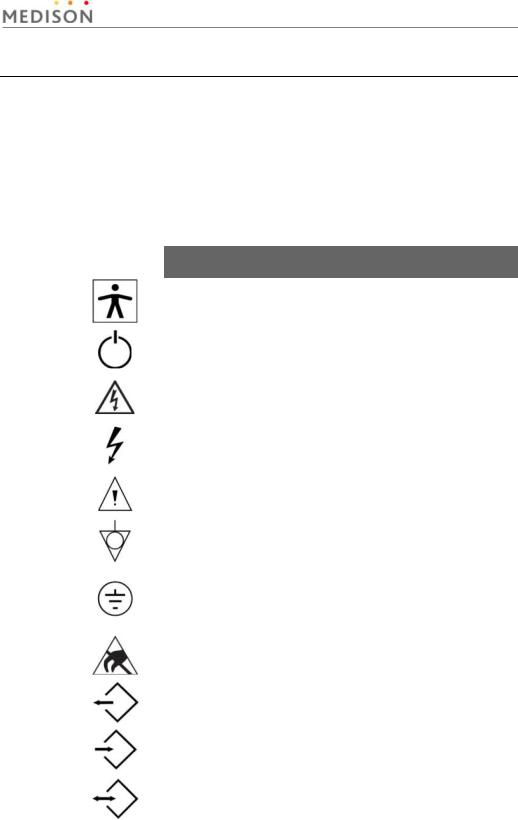
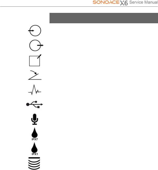
2.2.1Safety Symbols
The International Electro Technical Commission (IEC) has established a set of symbols for medical electronic equipment, which classifies a connection or warn of potential hazards. The classifications and symbols are shown below.
|
Symbols |
Description |
|
Isolated patient connection (Type BF applied part). |
|
|
Power switch (Supplies/cuts the power for product) |
|
|
Indicates a caution for risk of electric shock. |
|
|
Indicates dangerous voltages over 1000V AC or over |
|
|
1500V DC. |
|
|
Warning, Caution |
|
|
Identifies an equipotential ground. |
|
|
Identifies the point where the system safety ground is |
|
|
fastened to the chassis. Protective earth connected to |
|
|
conductive parts of Class I equipment for safety |
|
|
purposes. |
|
|
Electrostatic discharge |
|
|
Data Output port |
|
|
Data Input port |
|
|
Data Input/Output port |
|
Chapter 2. Safety 2-2
|
Symbols |
Description |
|
Left and right Audio / Video input |
|
|
Left and right Audio / Video output |
|
|
Print remote output |
|
|
Foot switch connector |
|
|
ECG connector |
|
|
USB connector |
|
|
Microphone connector |
|
|
Protection against the effects of immersion. |
|
|
Protection against dripping water. |
|
|
Probe connector |
|
Chapter 2. Safety 2-3
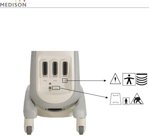
2.2.2Labels
To protect the system, you may see ‘Warning’ or ‘Caution’ marked on the surface of the product
1) Front
[Figure 2-1] Labels of Front
Chapter 2. Safety 2-4

2) Rear
[ Figure 2-2] Labels of Rear
Chapter 2. Safety 2-5
2.3Electrical Safety
This equipment has been verified as a Class I device with Type BF applied parts.
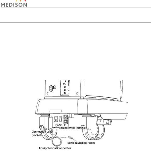
2.3.1Prevention of Electric Shock
In a hospital, dangerous currents are due to the potential differences between connected equipment and touchable conducting parts found in medical rooms. The solution to the problem is consistent equipotential bonding. Medical equipment is connected with connecting leads made up of angled sockets to the equipotential bonding network in medical rooms.
[Figure 2-3] Equipotential bonding
Additional equipment connected to medical electrical equipment must comply with the respective IEC or ISO standards (e.g. IEC 60950 for data processing equipment). Furthermore all configurations shall comply with the requirements for medical electrical systems (see IEC 60601-1-1 or clause 16 of the 3 Ed. of IEC 60601-1, respectively). Anybody connecting additional equipment to medical electrical equipment configures a medical system and is therefore responsible that the system complies with the requirements for medical electrical systems. Attention is drawn to the fact that local laws take priority over the above-mentioned requirements. If in doubt, consult your local distributor or the technical service department.
Chapter 2. Safety 2-6
yElectric shock may exist result if this system, including and all of its externally mounted recording and monitoring devices, is not properly grounded.
yDo not remove the covers on the system; hazardous voltages are present inside. Cabinet panels must be in place while the system is in use. All internal adjustments and replacements must be made by a qualified MEDISON Customer Service Department.
yCheck the face, housing, and cable before use. Do not use, if the face is cracked, chipped, or torn, the housing is damaged, or if the cable is abraded.
yAlways disconnect the system from the wall outlet prior to cleaning the system.
yAll patient contact devices, such as probes and ECG leads, must be removed from the patient prior to application of a high voltage defibrillation pulse.
yThe use of flammable anesthetic gas or oxidizing gases (N20) should be avoided.
yThe system has been designed for 100-120VAC and 200-240VAC; you should select the input voltage of monitor, printer and VCR. Prior to connecting an OEM power cord, verify that the voltage indicated on the power cord matches the voltage rating of the OEM device.
yAn isolation transformer protects the system from power surges. The isolation transformer continues to operate when the system is in standby.
yDo not immerse the cable in liquids. Cables are not waterproof.
yThe operator does not contact the parts (SIP/SOP) and the patient simultaneously
2.3.2ECG-Related Information
WARNING y This device is not intended to provide a primary ECG monitoring function, and therefore does not have means of indicating an inoperative
electrocardiograph.
yDo not use ECG electrodes of HF surgical equipment. Any malfunctions in the HF surgical equipment may result in burns to the patient.
yDo not use ECG electrodes during cardiac pacemaker procedures or other electrical stimulators.
yDo not use ECG leads and electrodes in an operating room.
Chapter 2. Safety 2-7
2.3.3ESD
Electrostatic discharge (ESD), commonly referredto as a static shock, is a naturally occurring phenomenon. ESD is most prevalent during conditions of low humidity, which can be caused by heating or air conditioning. During low humidity conditions, electrical charges naturally build up on individuals, creating static electricity. An ESD occurs when an individual with an electrical energy build-up comes in contact with conductive objects such as metal doorknobs, file cabinets, computer equipment, and even other individuals. The static shock or ESD is a discharge of the electrical energy build-up from a charged individual to a lesser or non-charged individual or object.
The ESD caution symbol is on the probe connector and the rear panel.
[Figure 2-4] ESD symbol
CAUTION y The level of electrical energy discharged from a system user or patient to an ultrasound system can be significant enough to cause
damage to the system or probes.
yThe following precautions can help to reduce ESD:
—Anti-static sprays on carpets or linoleum
—Anti-static mats
—A ground wire connection between the system and the patient table or bed.
2.3.4EMI
Although this system has been manufactured in compliance with existing EMI (Electromagnetic Interference) requirements, use of this system in the presence of an electromagnetic field can cause momentary degradation of the ultrasound image.
If this occurs often, MEDISON suggests a review of the environment in which the system is being used, to identify possible sources of radiated emissions. These emissions could be from other electrical devices used within the same room or an adjacent room. Communication devices such as cellular phones and pagers can cause these emissions. The existence of radios, TVs, or microwave transmission equipment nearby can also cause interference.
Chapter 2. Safety 2-8
CAUTION In cases where EMI is causing disturbances, it may be necessary to relocate this system.
2.3.5EMC
The testing for EMC(Electromagnetic Compatibility) of this system has been performed according to the international standard for EMC with medical devices (IEC60601-1-2). This IEC standard was adopted in Europe as the European norm (EN60601-1-2).
2.3.5.1Guidance and manufacturer’s declaration — electromagnetic emission
This product is intended for use in the electromagnetic environment specified below. The customer or the user of this product should assure that it is used in such an environment.
|
Emission test |
Compliance |
Electromagnetic environment -guidance |
|||
|
RF Emission |
Group 1 |
The Ultrasound System uses RF energy only |
|||
|
(Radiation) |
for its internal function. Therefore, its RF |
||||
|
Class B |
|||||
|
CISPR 11 |
emissions are very low and are not likely to |
||||
|
cause any interference in nearby electronic |
|||||
|
RF Emission |
Group 1 |
||||
|
(Radiation) |
equipment. |
||||
|
Class B |
|||||
|
CISPR 11 |
The Ultrasound System is suitable for use in |
||||
|
all establishments, including domestic |
|||||
|
Harmonic Emission |
Class A |
||||
|
IEC 61000-3-2 |
establishments and those directly connected |
||||
|
to the public low-voltage power supply |
|||||
|
Flicker Emission |
|||||
|
Complies |
network that supplies building used for |
||||
|
IEC 61000-3-3 |
|||||
|
domestic purpose. |
|||||
Chapter 2. Safety 2-9
![]()
2.3.5.2 Approved Cables, Transducers and Accessories for EMC 1) Approved Cable for Electromagnetic Compliance
Cables connected to this product may affect its emissions; Use only the cable types and lengths listed below table.
|
Cable |
Type |
Length |
|
VGA |
Shielded |
Normal |
|
Parallel |
Shielded |
Normal |
|
RS232C |
Shielded |
Normal |
|
USB |
Shielded |
Normal |
|
LAN(RJ45) |
Twisted pair |
Any |
|
S-Video |
Shielded |
Normal |
|
Foot Switch |
Shielded |
2.5m |
|
B/W Printer |
Unshielded Coaxial |
Normal |
|
MIC |
Unshielded |
Any |
|
Printer Remote |
Unshielded |
Any |
|
Audio R.L |
Shielded |
Normal |
|
VHS |
Shielded |
Normal |
|
ECG AUX input |
Shielded |
< 3m |
2) Approved Transducer for Electromagnetic Compliance
The probe listed in ‘Chapter 8. Probes’ when used with this product, have been tested to comply with the group1 class B emission as required by International Standard CISPR 11.
3) Approved Accessories for Electromagnetic Compliance
Accessories used with this product may effect its emissions.
CAUTION Whenconnectingothercustomer-suppliedaccessoriestothesystem,suchasa remoteprinterorVCR,itistheuser’sresponsibilitytoensuretheelectromagnetic compatibilityofthesystem.UseonlyCISPR11orCISPR22,CLASSBcompliant devices.
Chapter 2. Safety 2-10

|
Immunity test |
IEC 60601 |
Compliance level |
Electromagnetic environment — |
||||
|
Test level |
guidance |
||||||
|
Electrostatic |
Floors should be wood, |
||||||
|
discharge (ESD) |
±6KV Contact |
±6KV |
Contact |
concrete or ceramic tile. If floors |
|||
|
are covered with synthetic |
|||||||
|
IEC 61000-4-2 |
±8KV |
air |
±8KV |
air |
material, the relative humidity |
||
|
should be at least 30%. |
|||||||
|
Electrical fast |
±2KV |
for power |
±2KV for power |
Mains power quality should be |
|||
|
that of a typical commercial or |
|||||||
|
transient/burst |
supply lines |
supply lines |
|||||
|
hospital environment. |
|||||||
|
±1KV for input/output |
±1KV for input/ |
||||||
|
IEC 61000-4-4 |
lines |
output lines |
|||||
|
Surge |
±1KV differential |
Mains power quality should be |
|||||
|
±1KV differential mode |
|||||||
|
mode |
|||||||
|
IEC 61000-4-5 |
|||||||
|
±2KV common mode |
that of a typical commercial or |
||||||
|
±2KV common mode |
hospital environment. |
||||||
|
Voltage dips, short |
<5% Uт |
<5% Uт |
Mains power quality should be |
||||
|
interruptions and |
(>95% dip in Uт) |
(>95% dip in Uт) |
that of a typical commercial or |
||||
|
voltage variations |
for 0.5cycle |
for 0.5cycle |
hospital environment. If the user |
||||
|
on power supply |
of this product requires |
||||||
|
input lines |
40% Uт |
40% Uт |
continued operation during |
||||
|
(60% dip in Uт ) |
(60% dip in Uт ) |
power mains interruptions, it is |
|||||
|
IEC 61000-4-11 |
for 5 cycle |
for 5 cycle |
recommended that this product |
||||
|
be powered from an |
|||||||
|
70% Uт |
70% Uт |
uninterruptible power supply or a |
|||||
|
(30% dip in Uт) |
(30% dip in Uт) |
battery. |
|||||
|
for 25 cycle |
for 25 cycle |
||||||
|
<5% Uт |
<5% Uт |
||||||
|
(<95% dip in Uт ) |
(<95% dip in Uт ) |
||||||
|
for 5 s |
for 5 s |
||||||
|
Power frequency |
Power frequency magnetic fields |
||||||
|
(50/60Hz) |
should be at levels characteristic |
||||||
|
magnetic field |
3 A/m |
3 A/m |
of a typical location in a typical |
||||
|
commercial or hospital |
|||||||
|
IEC 61000-4-8 |
environment. |
NOTE Uт is the a.c. mains voltage prior to application of the test level.
Chapter 2. Safety 2-11

|
Conducted RF |
3 Vrms |
0.01V |
Portable and mobile RF communications |
|
IEC 61000-4-6 |
150 kHz to 80MHz |
equipment should be used no closer to any |
|
|
part of the Ultrasound System, including |
|||
|
cables, than the recommended separation |
|||
|
distance calculated from the equation |
|||
|
applicable to the frequency of the |
|||
|
transmitter. |
|||
|
Recommended separation distance |
|
80MHz to 800MHZ |
|||
|
800MHz to 2.5GHz |
|||
|
Radiated RF |
3 V/m |
3 V/m |
Where P is the maximum output power rating |
|
IEC 61000-4-3 |
80 MHz to 2.5GHz |
of the transmitter in watts (W) according to |
|
|
the transmitter manufacturer and d is the |
|||
|
recommended separation distance in meters |
|||
|
(m). |
|||
|
Field strengths from fixed RF transmitters, as |
|||
|
deter-mined by an electromagnetic site |
|||
|
survey,a should be less than the compliance |
|||
|
level in each frequency range. b |
|||
|
Interference may occur in the vicinity of |
|||
|
equipment marked with the following |
|||
|
symbol : |
NOTE 1) At 80MHz and 800MHz, the higher frequency range applies.
NOTE 2) These guidelines may not apply in all situations. Electromagnetic propagation is affected by absorption and reflection from structures, objects and people.
a Field strengths from fixed transmitters, such as base stations for radio (cellular/cordless) telephones and land mobile radios, amateur radio, AM and FM radio broadcast and TV broadcast cannot be predicted theoretically with accuracy. To assess the electromagnetic environment due to fixed RF transmitters, an electromagnetic site survey should be considered. If the measured field strength in the location in which the Ultrasound System is used exceeds the applicable RF compliance level above, the Ultrasound System should be observed to verify normal operation. If abnormal performance is observed, additional measures may be necessary, such as re-orienting or relocating the Ultrasound System or using a shielded location with a higher RF shielding effectiveness and filter attenuation.
b Over the frequency range 150kHz to 80MHz, field strengths should be less than [V1] V/m.
Chapter 2. Safety 2-12

2.3.5.3Recommended separation distances between portable and mobile RF communications equipment and the SONOACE X6
This product is intended for use in an electromagnetic environment in which radiated RF disturbances are controlled. The customer or the user of this product can help Prevent electromagnetic interference by maintaining a minimum distance between portable and mobile RF communications equipment (transmitters) and this product as recommended below, according to the maximum output power of the communications equipment.
|
Separation distance according to frequency of transmitter [m] |
|||
|
Rated maximum |
150kHz to 80MHz |
80MHz to 800MHz |
800MHz to 2.5GHz |
|
output power of |
|||
|
transmitter [W] |
|||
|
V1=0.01Vrms |
E1=3 V/m |
E1=3V/m |
|
|
0.01 |
35.00 |
0.11 |
0.23 |
|
0.1 |
110.68 |
0.36 |
0.73 |
|
1 |
350.00 |
1.16 |
2.33 |
|
10 |
1106.80 |
3.68 |
7.37 |
|
100 |
3500.00 |
11.66 |
23.33 |
For transmitters rated at a maximum output power not listed above, the recommended separation distance d in meters (m) can be estimated using the equation applicable to the frequency of the transmitter, where p is the maximum output power rating of the transmitter in watts (W) according to the transmitter manufacturer.
NOTE 1) At 80MHz and 800MHz, the separation distance for the higher frequency range applies.
NOTE 2) These guidelines may not apply in all situations. Electromagnetic propagation is affected by absorption and reflection from structures, objects and people.
2.3.5.4Electromagnetic environment – guidance
The Ultrasound System must be used only in a shielded location with a minimum RF shielding effectiveness and, for each cable that enters the shielded location. Field strengths outside the shielded location from fixed RF transmitters, as determined by an electromagnetic site survey, should be less than 3V/m.
It is essential that the actual shielding effectiveness and filter attenuation of the shielded location be verified to assure that they meet the minimum specification.
Chapter 2. Safety 2-13

If the system is connected to other customer-supplied equipment, such as a CAUTION local area network (LAN) or a remote printer, Medison cannot guarantee that the
remote equipment will work correctly in the presence of electromagnetic phenomena.
2.3.5.5Avoiding Electromagnetic Interference
A medical device can either generate or receive electromagnetic interference. The EMC standards describe tests for both emitted and received interference.
Medison Ultrasound System does not generate interference in excess of the referenced standards.
An Ultrasound System is designed to receive signals at radio frequency and is therefore susceptible to interference generated by RF energy sources. Examples of other source of interference are medical device, information technology products, and radio and television transmission towers. Tracing the source of radiated interference can be a difficult task. Customers should consider the following in an attempt to locate the source:
yIs the interference intermittent or constant?
yDoes the interference show up only with one transducers operating at the same frequency or with several transducer?
yDo two different transducer operating at the same frequency have the same problem?
yIs the interference present if the system is moved to a different location in the facility?
The answers to these questions will help determine if the problem reside with the system or the scanning environment. After you answer the question, contact your local MEDISON customer service department.
Chapter 2. Safety 2-14

2.4Mechanical Safety
2.4.1Moving the Equipment
Before transporting the product, check that the brakes on the front wheels are unlocked. Also, make sure to retract the monitor arm completely so that it is secured in a stationary position.
Always use the handles at the back of the console and move the product slowly.
This product is designed to resist shocks. However, excessive shock, for example if the product falls over, may cause serious damage.
If the system operates abnormally after repositioning, please contact the MEDISON Customer Service Department.
WARNING The product weighs more than 60kg. Be extra careful when transporting it. Careless transportation of the product may result in product damage or personal injury
2.4.1.1The Brakes
Brakes are mounted to the front wheels of the console only. To lock the brakes, press the top part of the brake with your foot. To unlock them, press the part labeled Off at the bottom of the brake with your foot.
You can use the brakes to control the movement of the product. We recommend that you lock the brakes when using the product.
[Figure 2-5] Precautions on Ramps
Chapter 2. Safety 2-15

2.4.1.2Precautions on Ramps
Always make sure that control panel is facing the direction of movement
When moving the product down a ramp or resting it temporarily on a ramp, the product may tilt over even with the brakes on depending on the direction of the product. Do not rest the product on ramps.
WARNING Be aware of the castors, especially when moving the system. MEDISON recommends that you exercise caution when moving the product up or down ramps
2.4.2 Safety Note
yDo not press the control panel excessively.
yNever attempt to modify the product in any way.
yCheck the operational safety when using the product after a prolonged break in service.
yMake sure that other objects, such as metal pieces, do not enter the
CAUTION system.
yDo not block the ventilation slots.
yTo prevent damage to the power cord, be sure to grip the plug head
– not the cord – when unplugging.
yExcessive bending or twisting of cables on patient-applied parts may cause failure or intermittent operation of the system.
yImproper cleaning or sterilization of a patient-applied part may cause permanent damage.
Chapter 2. Safety 2-16

2.5Biological Safety
Verify the alignment of the Probe before use. See the “Chapter 9. Probes” section of this manual.
|
WARNING |
y Ultrasound waves may have damaging effects on cells and, |
|
therefore, may be harmful to the patient. If there is no medical |
|
|
benefit, minimize the exposure time and maintain the ultrasound |
|
|
wave output level at low. Please refer to the ALARA principle. |
yDo not use the system if an error message appears on the video display indicating that a hazardous condition exists. Note the error code, turn off the power to the system, and call your local MEDISON Customer Service Department.
yDo not use a system that exhibits erratic or inconsistent updating. Discontinuities in the scanning sequence are indicative of a hardware failure that should be corrected before use.
yThe system limits the maximum contact temperature to 43 degree Celsius, and the ultrasonic waves output observes American FDA regulations.
2.5.1ALARA Principle
Guidance for the use of diagnostic ultrasound is defined by the “as low as reasonably achievable” (ALARA) principle. The decision as to what is reasonable has been left to the judgment and insight of qualified personnel. No set of rules can be formulated that would be sufficiently complete to dictate the correct response for every circumstance. By keeping ultrasound exposure as low as possible, while obtaining diagnostic images, users can minimize ultrasonic bioeffects.
Since the threshold for diagnostic ultrasound bioeffects is undetermined, it is the sonographer’s responsibility to control the total energy transmitted into the patient. The sonographer must reconcile exposure time with diagnostic image quality. To ensure diagnostic image quality and limit exposure time, the ultrasound system provides controls that can be manipulated during the exam to optimize the results of the exam.
The ability of the user to abide by the ALARA principle is important. Advances in diagnostic ultrasound not only in the technology but also in the applications of the technology, have resulted in the need for more and better information to guide the user. The output indices are designed to provide that important information There are a number of variables, which affect the way in which the output display indices can be used to implement the ALARA principle. These variables include mass, body size, location of the bone relative to the focal point, attenuation in the body, and ultrasound exposure time. Exposure time is an especially useful variable, because the user controls it. The ability to limit the index values over time support the ALARA principle.
Chapter 2. Safety 2-17

2.5.1.1ApplyingALARA
The system-imaging mode used depends upon the information needed. 2D-mode and M-mode imaging provide anatomical information, while Doppler, Power, and Color imaging provide information about blood flow. Scanned modes, like 2Dmode, Power, or Color, disperse or scatter the ultrasonic energy over an area, while an unscanned mode, like M-mode or Doppler, concentrates ultrasonic energy. Understanding the nature of the imaging mode being used allows the sonographer to apply the ALARA principle with informed judgment. The probe frequency, system set-up values, scanning techniques, and operator experience aid the sonographer in meeting the definition of the ALARA principle.
The decision as to the amount of acoustic output is, in the final analysis, up to the system operator. This decision must be based on the following factors: type of patient, type of exam, patient history, ease or difficulty of obtaining diagnostically useful information, and the potential localized heating of the patient due to probe surface temperatures. Prudent use of the system occurs when patient exposure is limited to the lowest index reading for the shortest amount of time necessary to achieve acceptable diagnostic results.
Although a high index reading does not mean that a bioeffect is actually occurring, a high index reading should be taken seriously. Every effort should be made to reduce the possible effects of a high index reading. Limiting exposure time is an effective way to accomplish this goal.
There are several system controls that the operator can use to adjust the image quality and limit the acoustic intensity. These controls are related to the techniques that an operator might use to implement ALARA. These controls can be divided into three categories: direct, indirect, and receiver control.
2.5.1.2Direct Controls
Application selection and the output intensity control directly affect acoustic intensity. There are different ranges of allowable intensity or output based on your selection. Selecting the correct range of acoustic intensity for the application is one of the first things required during any exam. For example, peripheral vascular intensity levels are not recommended for fetal exams. Some systems automatically select the proper range for a particular procedure, while others require manual selection. Ultimately, the user bears the responsibility for proper clinical use. The MEDISON system provides both automatic and user-definable settings.
Output has direct impact on acoustic intensity. Once the application has been established, the output control can be used to increase or decrease the intensity output. The output control allows you to select intensity levels less than the defined maximum. Prudent use dictates that you select the lowest output intensity consistent with good image quality.
Chapter 2. Safety 2-18

2.5.1.3Indirect Controls
The indirect controls are those that have an indirect effect on acoustic intensity. These controls affect imaging mode, pulse repetition frequency, focus depth, pulse length, and probe selection.
The choice of imaging mode determines the nature of the ultrasound beam. 2Dmode is a scanning mode, Doppler is a stationary or unscanned mode. A stationary ultrasound beam concentrates energy on a single location. A moving or scanned ultrasound beam disperses the energy over a wide area and the beam is only concentrated on a given area for a fraction of the time necessary in unscanned mode.
Pulse repetition frequency or rate refers to the number of ultrasound bursts of energy over a specific period of time. The higher the pulse repetition frequency, the more pulses of energy in a given period of time. Several controls affect pulse repetition frequency: focal depth, display depth, sample volume depth, color sensitivity, number of focal zones, and sector width controls.
Focus of the ultrasound beam affects the image resolution. To maintain or increase resolution at a different focus requires a variation in output over the focal zone. This variation of output is a function of system optimization. Different exams require different focal depths. Setting the focus to the proper depth improves the resolution of the structure of interest.
Pulse length is the time during which the ultrasonic burst is turned on. The longer the pulse, the greater the time-average intensity value. The greater the timeaverage intensity, the greater the likelihood of temperature increase and cavitations. Pulse length or burst length or pulse duration is the output pulse duration in pulsed Doppler. Increasing the Doppler sample volume increases the pulse length.
Probe selection affects intensity indirectly. Tissue attenuation changes with frequency. The higher the probe operating frequency, the greater the attenuation of the ultrasonic energy. Higher probe operating frequencies require higher output intensity to scan at a deeper depth. To scan deeper at the same output intensity, a lower probe frequency is required. Using more gain and output beyond a point, without corresponding increases in image quality, can mean that a lower frequency probe is needed.
2.5.1.4Receiver Controls
Receiver controls are used by the operator to improve image quality. These controls have no effect on output. Receiver controls only affect how the ultrasound echo is received. These controls include gain, TGC, dynamic range, and image processing. The important thing to remember, relative to output, is that receiver controls should be optimized before increasing output. For example; before increasing output, optimize gain to improve image quality.
2.5.1.5AdditionalConsiderations
Ensure that scanning time is kept to a minimum, and ensure that only medically required scanning is performed. Never compromise quality by rushing through an exam. A poor exam will require a follow-up, which ultimately increases the time. Diagnostic ultrasound is an important tool in medicine, and, like any tool, should be used efficiently and effectively.
Chapter 2. Safety 2-19
![]()
2.5.1.6Output Display Features
The system output display comprises two basic indices: a mechanical index and a thermal index. The thermal index consists of the following indices: soft tissue (TIs), bone (TIb) and cranial bone (TIc). One of these three thermal indices will be displayed at all times. Which one depends upon the system preset or user choice, depending upon the application at hand.
The mechanical index is continuously displayed over the range of 0.0 to 1.9, in increments of 0.1.
The thermal index consists of the three indices, and only one of these is displayed at any one time. Each probe application has a default selection that is appropriate for that combination. The TIb or TIs is continuously displayed over the range of 0.0 to maximum output, based on the probe and application, in increments of 0.1.
The application-specific nature of the default setting is also an important factor of index behavior. A default setting is a system control state which is preset by the manufacturer or the operator. The system has default index settings for the probe application. The default settings are invoked automatically by the ultrasound system when power is turned on, new patient data is entered into the system database, or a change in application takes place.
The decision as to which of the three thermal indices to display should be based on the following criteria:
Appropriate index for the application: TIs is used for imaging soft tissue; and TIb for a focus at or near bone. Some factors might create artificially high or low thermal index readings e.g. presence of fluid or bone, or the flow of blood. A highly attenuating tissue path, for example, will cause the potential for local zone heating to be less than the thermal index displays.
Scanned modes versus unscanned modes of operation affect the thermal index. For scanned modes, heating tends to be near the surface; for unscanned modes, the potential for heating tends to be deeper in the focal zone.
Always limit ultrasound exposure time. Do not rush the exam. Ensure that the indices are kept to a minimum and that exposure time is limited without compromising diagnostic sensitivity.
1)Mechanical Index (MI) Display
Mechanical bioeffects are threshold phenomena that occur when a certain level of output is exceeded. The threshold level varies, however, with the type of tissue. The potential for mechanical bioeffects varies with peak pressure and ultrasound frequency. The MI accounts for these two factors. The higher the MI value, the greater the likelihood of mechanical bioeffects occurring but there is no specific MI value that means that a mechanical effect will actually occur. The MI should be used as a guide for implementing the ALARA principle
2)Thermal Index (TI) Display
The TI informs the user about the potential for temperature increase occuring at the body surface, within body tissue, or at the point of focus of the ultrasound beam on bone. The TI is an estimate of the temperature increase in specific body tissues. The actual amount of any temperature rise is influenced by factors such as tissue type, vascularity, and mode of operation etc. The TI should be used as a guide for implementing the ALARA principle.
The bone thermal index (TIb) informs the user about potential heating at or near the focus after the ultrasound beam has passed through soft tissue or fluid, for
Chapter 2. Safety 2-20

example, at or near second or third trimester fetal bone.
The cranial bone thermal index (TIc) informs the user about the potential heating of bone at or near the surface, for example, cranial bone.
The soft tissue thermal index (TIs) informs the user about the potential for heating within soft homogeneous tissue.
You can select either TIs or TIb using the TIs/TIb selection on the Miscellaneous system setups. TIc is displayed when you select a trans-cranial application.
3)Mechanical and Thermal indices Display Precision and Accuracy
The Mechanical and Thermal Indices on the system are precise to 0.1 units. The MI and TI display accuracy estimates for the system are given in the Acoustic Output Tables manual. These accuracy estimates are based on the variability range of probes and systems, inherent acoustic output modeling errors and measurement variability, as described below.
The displayed values should be interpreted as relative information to help the system operator achieve the ALARA principle through prudent use of the system. The values should not be interpreted as actual physical values investigated tissue or organs. The initial data that is used to support the output display is derived from laboratory measurements based on the AIUM measurement standard. The measurements are then put into algorithms for calculating the displayed output values.
Many of the assumptions used in the process of measurement and calculation are conservative in nature. Over-estimation of actual in situ exposure, for the vast majority of tissue paths, is built into the measurement and calculation process. For example:
The measured water tank values are de-rated using a conservative, industry standard, attenuation coefficient of 0.3dB/cm-MHz.
Conservative values for tissue characteristics were selected for use in the TI models. Conservative values for tissue or bone absorption rates, blood perfusion rates, blood heat capacity, and tissue thermal conductivity were selected. Steady state temperature rise is assumed in the industry standard TI models, and the assumption is made that the ultrasound probe is held steady in one position long enough for steady state to be reached.
A number of factors are considered when estimating the accuracy of display values: hardware variations, algorithm accuracy estimation and measurement variability. Variability among probes and systems is a significant factor. Probe variability results from piezoelectric crystal efficiencies, process-related impedance differences, and sensitive lens focusing parameter variations. Differences in the system pulse voltage control and efficiencies are also a contributor to variability. There are inherent uncertainties in the algorithms used for estimating acoustic output values over the range of possible system operating conditions and pulse voltages. Inaccuracies in laboratory measurements are related to differences in hydrophone calibration and performance, positioning, alignment and digitization tolerances, and variability among test operators.
The conservative assumptions of the output estimation algorithms of linear propagation, at all depths, through a 0.3dB/cm-MHz attenuated medium are not taken into account in calculation of the accuracy estimate displayed. Neither linear propagation, nor uniform attenuation at the 0.3dB/cm-MHz rate, occurs in water tank measurements or in most tissue paths in the body. In the body,
Chapter 2. Safety 2-21

different tissues and organs have dissimilar attenuation characteristics. In water, there is almost no attenuation. In the body, and particularly in water tank measurements, non-linear propagation and saturation losses occur as pulse voltages increase.
The display accuracy estimates take into account the variability ranges of probes and systems, inherent acoustic output modeling errors, and measurement variability. Display accuracy estimates are not based on errors in, or caused by measuring according to, the AIUM measurement standards. They are also independent of the effects of non-linear loss on the measured values.
2.5.1.7Control Affecting the indices
As various system controls are adjusted, the TI and MI values may change. This will be most apparent as the POWER control is adjusted; however, other system controls will affect the on-screen output values.
1)POWER
Power controls the system acoustic output. Two real-time output values are on the screen: a TI and a MI. They change as the system responds to POWER adjustments.
In combined modes, such as simultaneous Color, 2D-mode and pulsed Doppler, the individual modes each add to the total TI. One mode will be the dominant contributor to this total. The displayed MI will be from the mode with the largest peak pressure.
2.5.1.82D Mode Controls
1)2D-mode size
Narrowing the sector angle may increase the frame rate. This action will increase the TI. Pulse voltage may be automatically adjusted down with software controls to keep the TI below the system maximums. A decrease in pulse voltage will decrease MI.
2) Zoom
Increasing the zoom magnification may increase frame rate. This action will increase the TI. The number of focal zones may also increase automatically to improve resolution. This action may change MI since the peak intensity can occur at a different depth.
3) Persistence
A lower persistence will decrease the TI. Pulse voltage may be automatically increased. An increase in pulse voltage will increase MI.
4) Focal no.
More focal zones may change both the TI and MI by changing frame rate or focal depth automatically. Lower frame rates decrease the TI. MI displayed will correspond to the zone with the largest peak intensity.
5) Focus
Changing the focal depth will change the MI. Generally, higher MI values will occur when the focal depth is near the natural focus of the transducer.
Chapter 2. Safety 2-22

2.5.1.9 Color and Power Controls
1) Color Sensitivity
Increasing the color sensitivity may increase the TI. More time is spent scanning for color images.
Color pulses are the dominant pulse type in this mode.
2) Color Sector Width
Narrower color sector width will increase color frame rate and the TI will increase. The system may automatically decrease pulse voltage to stay below the system maximum. A decrease in pulse voltage will decrease the MI. If pulsed Doppler is also enabled then pulsed Doppler will remain the dominant mode and the TI change will be small.
3) Color Sector Depth
Deeper color sector depth may automatically decrease color frame rate or select a new color focal zone or color pulse length. The TI will change due to the combination of these effects. Generally, the TI will decrease with increased color sector depth. MI will correspond to the peak intensity of the dominant pulse type, which is a color pulse. However, if pulsed Doppler is also enabled then pulsed Doppler will remain the dominant mode and the TI change will be small.
4) Scale
Using the SCALE control to increase the color velocity range may increase the TI. The system will automatically adjust pulse voltage to stay below the system maximums. A decrease in pulse voltage will also decrease MI.
5) Sec Width
A narrower 2D-mode sector width in Color imaging will increase color frame rate. The TI will increase. MI will not change. If pulsed Doppler is also enabled, then pulsed Doppler will remain as the primary mode and the TI change will be small.
2.5.1.10 M mode and Doppler Controls
1) Speed
M-mode and Doppler sweep speed adjustments will not affect the MI. When M- mode sweep speed changes, TI changes.
2) Simultaneous and Update Methods
Use of combination modes affects both the TI and MI through the combination of pulse types. During simultaneous mode, the TI is additive. During autoupdate and duplex, the TI will display the dominant pulse type. The displayed MI will be from the mode with the largest peak pressure.
3) Sample Volume Depth
When Doppler sample volume depth is increased the Doppler PRF may automatically decrease. A decrease in PRF will decrease the TI. The system may also automatically decrease the pulse voltage to remain below the system maximum. A decrease in pulse voltage will decrease MI.
Chapter 2. Safety 2-23

2.5.1.11DOPPLER, CW, M MODE, andCOLOR ImagingControls
When a new imaging mode is selected, both the TI and the MI will change to default settings. Each mode has a corresponding pulse repetition frequency and maximum intensity point. In combined or simultaneous modes, the TI is the sum of the contribution from the modes enabled and MI is the MI for the focal zone and mode with the largest derated intensity. If a mode is turned off and then reselected, the system will return to the previously selected settings.
1) Probe
Each probe model available has unique specifications for contact area, beam shape, and center frequency. Defaults are initialized when you select a probe. MEDISON factory defaults vary with probe, application, and selected mode.
Defaults have been chosen below the FDA limits for intended use.
2) Depth
An increase in 2D-mode depth will automatically decrease the 2D-mode frame rate. This would decrease the TI. The system may also automatically choose a deeper 2D-mode focal depth. A change of focal depth may change the MI. The MI displayed is that of the zone with the largest peak intensity.
3) Application
Acoustic output defaults are set when you select an application. MEDISON factory defaults vary with probe, application, and mode. Defaults have been chosen below the FDA limits for intended use.
2.5.1.12Related GuidanceDocuments
For more information about ultrasonic bioeffects and related topics refer to the following;
yAIUM Report, January 28, 1993, “Bioeffects and Safety of Diagnostic Ultrasound”
yBioeffects Considerations for the Safety of Diagnostic Ultrasound, J Ultrasound Med., Sept. 1998: Vol. 7, No. 9 Supplement
yAcoustic Output Measurement Standard for Diagnostic Ultrasound Equipment. (AIUM, NEMA. 1998)
yAcoustic Output Labeling Standard for Diagnostic Ultrasound Equipment (AIUM, 1998)
ySecond Edition of the AIUM Output Display Standard Brochure, Dated March 10, 1994. (A copy of this document is shipped with each system.)
yInformation for Manufacturer Seeking Marketing Clearance of Diagnostic Ultrasound Systems and Transducers. FDA. September 1997. FDA.
yStandard for Real-Time Display of Thermal and Mechanical Acoustic Output Indices on Diagnostic Ultrasound Equipment. (Revision 1, AIUM, NEMA. 1998)
yWFUMB. Symposium on Safety of Ultrasound in Medicine: Conclusions and Recommendations on Thermal and Non-Thermal Mechanisms for Biological Effects of Ultrasound, Ultrasound in Medicine and Biology, 1998: Vol. 24, Supplement1.
Chapter 2. Safety 2-24

2.5.1.13Acoustic Output andMeasurement
Since the first usage of diagnostic ultrasound, the possible human biological effects (bioeffects) of ultrasound exposure have been studied by various scientific and medical institutions. In October 1987, the American Institute of Ultrasound in Medicine(AIUM) ratified a report prepared by its Bioeffects Committee (Bioeffects Considerations for the Safety of Diagnostic Ultrasound, J Ultrasound Med., Sept. 1988: Vol.7, No.9 Supplement), sometimes referred to as the Stowe Report, which reviewed available data on possible effects of ultrasound exposure. Another report “Bioeffects and Safety of Diagnostic Ultrasound,” dated January 28, 1993 provides more up to date information.
The acoustic output for this system has been measured and calculated in accordance with the December 1985 “510(K) Guide for Measuring and Reporting Acoustic Output of Diagnostic Ultrasound Medical Devices,” except that the hydrophone meets the requirements of “Acoustic Output Measurement Standard for Diagnostic Ultrasound Equipment” (NEMA UD 2-1992)
2.5.1.14In Situ, Derated, and Water Value Intensities
All intensity parameters are measured in water. Since water does not absorb acoustic energy, these water measurements represent a worst case value. Biological tissue does absorb acoustic energy. The true value of the intensity at any point depends on the amount and type of tissue and the frequency of the ultrasound that passes through the tissue. The intensity value in the tissue, In Situ, has been estimated using the following formula:
In Situ = Water [e−(0.23alf ) ]
|
where: |
In Situ = In Situ Intensity Value |
|
Water = Water Value Intensity |
|
|
e = 2.7183 |
|
|
a = Attenuation Factor |
|
|
Tissue |
a(dB/cm-MHz) |
|
Brain |
.53 |
|
Heart |
.66 |
|
Kidney |
.79 |
|
Liver |
.43 |
|
Muscle |
.55 |
l = skin line to measurement depth (cm)
f = Center frequency of the transducer/system/mode combination(MHz)
Since the ultrasonic path during an examination is likely to pass through varying lengths and types of tissue, it is difficult to estimate the true In Situ intensity. An attenuation factor of 0.3 is used for general reporting purpose; therefore, the In Situ value which is commonly reported uses the formula:
In Situ (derated) = Water [e−(0.069lf ) ]
Since this value is not the true In Situ intensity, the term “derated” is used.
The maximum derated and the maximum water values do not always occur at the
Chapter 2. Safety 2-25

same operating condition; therefore, the reported maximum water and derated values may not be related to the In Situ (derated) formula. Take for example a multi-zone array transducer that has maximum water value intensities in its deepest zone: the same transducer may have its largest derated intensity in one if its shallowest focal zones.
2.5.1.15AcousticOutputandMeasurement
The terms and symbols used in the acoustic output tables are defined in the following paragraphs.
|
ISPTA.3 |
The derated spatial-peak temporal-average intensity (milliwatts |
|
per square centimeter). |
|
|
ISPPA.3 |
The derated spatial-peak pulse-average intensity (watts per square |
|
centimeter). The value of IPA.3 at the position of global maximum |
|
|
MI (IPA.3@MI) may be reported instead of ISPPA.3 if the global |
|
|
maximum MI is reported. |
|
|
MI |
The Mechanical Index. The value of MI at the position of ISPPA.3, |
|
(MI@ISPPA.3) may be reported instead of MI (global maximum |
|
|
value) if ISPPA.3 is 190W/cm2 |
|
|
Pr.3 |
The derated peak rarefactional pressure (megapascals) associated |
|
with the transmit pattern giving rise to the reported MI value. |
|
|
WO |
The ultrasonic power (milliwatts). For the operating condition giving |
|
rise to ISPTA.3, WO is the total time-average power;. For |
|
|
operating conditions subject to reporting under ISPPA.3, WO is the |
|
|
ultrasonic power associated with the transmit pattern giving rise to |
|
|
the value reported under ISPPA.3 |
|
|
fc |
The center frequency (MHz). For MI and ISPPA.3, fc is the center |
|
frequency associated with the transmit pattern giving rise to the |
|
|
global maximum value of the respective parameter. For ISPTA.3, for |
|
|
combined modes involving beam types of unequal center |
|
|
frequency, fc is defined as the overall ranges of center frequencies |
|
|
of the respective transmit patterns. |
|
|
ZSP |
The axial distance at which the reported parameter is measured |
|
(centimeters). |
|
|
x-6,y-6 |
are respectively the in-plane (azimuth) and out-of-plane |
|
(elevation) -6 dimensions in the x-y plane where ZSP is found |
|
|
(centimeters). |
|
|
PD |
The pulse duration (microseconds) associated with the transmit |
|
pattern giving rise to the reported value of the respective |
|
|
parameter. |
|
|
PRF |
The pulse repetition frequency (Hz) associated with the transmit |
|
pattern giving rise to the reported value of the respective |
|
|
parameter. |
Chapter 2. Safety 2-26

|
EBD |
The entrance beam dimensions for the azimuth and elevation planes |
|
(centimeters). |
|
|
EDS |
The entrance dimensions of the scan for the azimuth and elevation |
|
planes (centimeters). |
2.5.1.16Acoustic Measurement Precision and Uncertainty
The Acoustic Measurement Precision and Acoustic Measurement Uncertainty are described below
|
Quantity |
Precision |
Total Uncertainty |
|
|
PII.3 (derated pulse intensity integral) |
3.2 % |
+21 % to — 24 % |
|
|
Wo (acoustic power) |
6.2 % |
+/- 19 % |
|
|
Pr.3 (derated rarefaction pressure) |
5.4 % |
+/- 15 % |
|
|
Fc (center frequency) |
< 1 % |
+/- 4.5 % |
1) Systematic Uncertainties
For the pulse intensity integral, derated rarefaction pressure Pr.3, center frequency and pulse duration, the analysis includes considerations of the effects on accuracy of:
Hydrophone calibration drift or errors.
Hydrophone / Amp frequency response. Spatial averaging.
Alignment errors.
Voltage measurementaccuracy, including.
yOscilloscope vertical accuracy.
yOscilloscope offset accuracy.
yOscilloscope clock accuracy.
yOscilloscope Digitization rates.
yNoise.
The systematic uncertainties Acoustic power measurements using a Radiation Force are measured through the use of calibrated NIST acoustic power sources. We also refer to a September 1993 analysis done by a working group of the IEC technical committee 87 and prepared by K. Beissner, as a first supplement to IEC publication 1161.
The document includes analysis and discussion of the sources of error / measurement effects due to:
yBalance system calibration.
yAbsorbing (or reflecting) target suspension mechanisms.
yLinearity of the balance system.
yExtrapolation to the moment of switching the ultrasonic transducer (compensation for
Chapter 2. Safety 2-27

ringing and thermal drift).
yTarget imperfections.
yAbsorbing (reflecting) target geometry and finite target size.
yTarget misalignment.
yUltrasonic transducer misalignment.
yWater temperature.
yUltrasonic attenuation and acoustic streaming.
yCoupling or shielding foil properties.
yPlane-wave assumption.
yEnvironmental influences.
yExcitation voltage measurement.
yUltrasonic transducer temperature.
yEffects due to nonlinear propagation and saturation loss.
The overall findings of the analysis give a rough Acoustic Power accuracy figure of +/- 10% for the frequency range of 1 — 10 MHz.
Chapter 2. Safety 2-28

2.6Environmental Protection
CAUTION y The console and peripherals could be sent back to manufacturers for recycling or proper disposal after their useful lives.
yDisposal of waste shall be disposed in accordance with national laws.
yThe waste sheaths are to be disposed of safely and national regulations must be observed.
 Waste Electrical and Electronic Equipment
NOTE This symbol is applied in the European Union and other European countries
This symbol on the product indicates that this product shall not be treated as household waste. Instead it shall be handed over to the applicable collection point for the recycling of electrical and electronic equipment. By ensuring this product is disposed of correctly, you will help prevent potential negative consequences for the environment and human health, which could otherwise be caused by inappropriate waste handling of this product. The recycling of materials will help to conserve natural resources. For more detailed information about recycling of this product, please contact your local city office, your electrical and electronic waste disposal service or the shop where you purchased the product.
Chapter 2. Safety 2-29
 Loading…
Esaote
MYLAB SIGMA ESAOTE
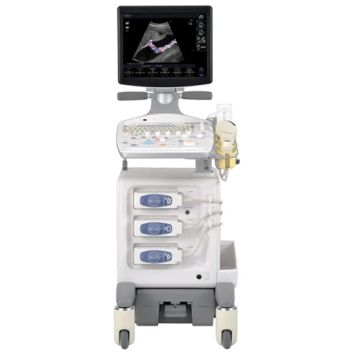 Loading…
Esaote
MYLAB SIGMA ESAOTE
Hitachi
Hitachi F37 (снят с производства)
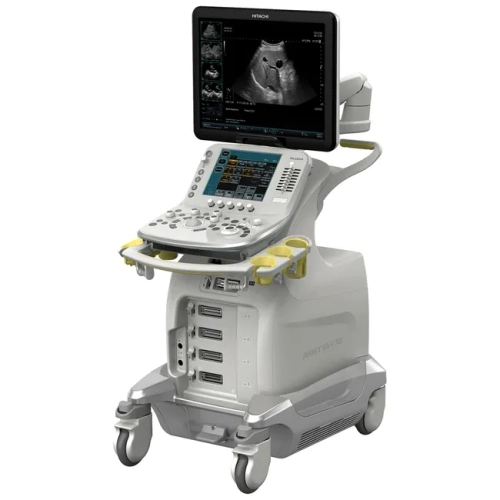
Hitachi
Hitachi Arietta V70 (снят с производства)
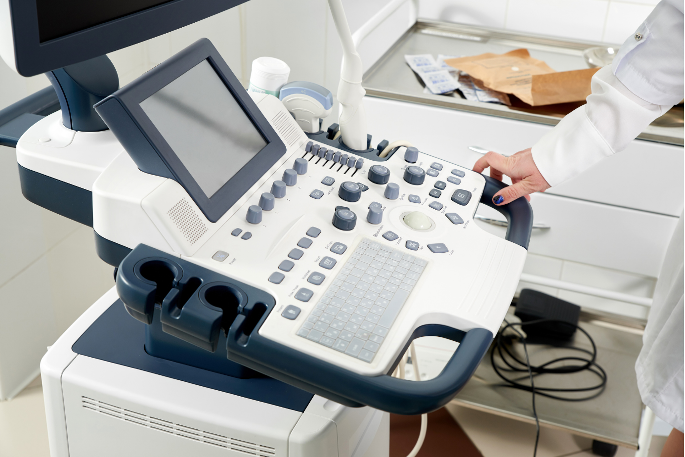
Hitachi
Hitachi Arietta 50le
Hitachi
Hitachi Arietta 65
Hitachi
HITACHI ALOKA ARIETTA S60
Hitachi-Aloka
Prosound Alpha 5
Esaote
Стационарный ультразвуковой аппарат MyLab 40 Esaote
Hitachi-Aloka
Prosound C3 CV
Samsung Medison