- Manuals
- Brands
- SoundCraft Manuals
- Music Mixer
- Si Impact
- User manual
-
Contents
-
Table of Contents
-
Bookmarks
Quick Links
®
User Guide
V1.4
For Soundcraft Si Impact Console
®
Related Manuals for SoundCraft Si Impact
Summary of Contents for SoundCraft Si Impact
-
Page 1
® User Guide V1.4 For Soundcraft Si Impact Console ®… -
Page 2: Safety
Soundcraft is a trading division of Harman International Industries Ltd. Information in this manual is subject to change without notice and does not represent a commitment on the part of the vendor. Soundcraft shall not be liable for any loss or damage whatsoever arising from the use of information or any error contained in this manual. No part of this…
-
Page 3: Table Of Contents
CONTENTS CONTENTS 1.0 AN INTRODUCTION TO Si IMPACT 7.0: DSP Elements 1.1: Safety 1.2: arranty 2.0: GETTING STARTED 8.0: MIX FEATURES 3.0: ASSIGNABLE CONTROLS 4.0: TOUCH SCREEN OPERATION 9.0: SHOWS, CUELISTS, AND SNAPSHOTS 4.1: Main Menu 5.0: INPUTS & OUTPUTS 9.2.1: Edit Cue…
-
Page 4
User Manual INTRODUCTION TO IMPACT The Soundcraft Si impact is a compact digital console optimised for live sound. It s powerful, yet simple to use, with intuitive controls, consistent colour-coded feedbac , and rapid parameter access. Features such as analogue, MADI, and USB I/O as standard, motorised faders, the Assignable… -
Page 5: Safety Notices
1.1: SAFETY User Manual INTRODUCTION SAFET SAFETY NOTICES t nt S m ti ns N tes Alerts the user to the presence of important Contain important information operating and maintenance (servicing) and useful tips on the operation instructions in the literature accompanying of your equipment.
-
Page 6
Soundcraft dealer. s ne s e s, t le l t s, t ins et . -
Page 7
1.1: SAFETY User Manual INTRODUCTION SAFET Although your new console will not output any sound until you feed it signals, it has the can damage hearing over time. Please ta e care when wor ing with your audio if you are manipulating controls which you don t understand (which we all do when we are learning), ma e sure your monitors are turned down. -
Page 8: Arranty
Equipment or the defective component should be returned to the Dealer or to Soundcraft and subject to the following conditions the Dealer or Soundcraft will repair or replace the defec- tive components. Any components replaced will become the property of Soundcraft.
-
Page 9
1.3: SPECIFICATIONS User Manual INTRODUCTION SPECIFICATIONS Si IMPACT TYPICAL SPECIFICATIONS — Mic / Line In to any Output: +/-1.5dB, 20H -20 H — 31H 16KH 1/3 octave T.H.D. Di it l I O — Mic Sensitivity -30dBu 0.01 @ 1 H… -
Page 10: Getting Started
OFF — AN INTRODUCTION TO THIS MANUAL Anyone with minimal audio experience should be able to operate the Si Impact console without reading too much of this manual, though we do recommend you ta e the time to go through it.
-
Page 11: Assignable Controls
For full detail on the Si Impact s assignable controls, please see section 3. Also note that the MI 1-14 Busses and Bus masters serve the same function as Auxiliary Mix busses and masters.
-
Page 12
2.2: PARTS OF THE CONSOLE User Manual ETTIN STARTED PARTS OF THE CONSOLE 2.2: ETTIN STARTED PARTS OF THE CONSOLE… -
Page 13
2.2: PARTS OF THE CONSOLE User Manual ETTIN STARTED PARTS OF THE CONSOLE 2.2: ETTIN STARTED PARTS OF THE CONSOLE… -
Page 14
ETTIN STARTED FADER LO Soundcraft Fader low is a unique feature that gives the user an additional level of status Several different functions can be assigned to the console faders, so it can be easy to lose trac of which function is currently being controlled, especially when grabbing a fader in a hurry. -
Page 15
User Manual ASSI NABLE CONTROLS At the heart of the Si Impact is a group of assignable controls that ma e the console easier and faster to navigate and operate. Assignable controls wor by changing the function of sections of the console surface. -
Page 16
3.1: FADER LAYERS User Manual ASSI NABLE CONTROLS FADER LA ERS The are four main Fader Layers on the Impact console, selected by the FADERS button group (A, B, C, and D) to the right of the Control Channels. The additional buttons in this group assign raphic bands across the faders for convenient control. -
Page 17
3.2: CONTROL CHANNELS User Manual ASSI NABLE CONTROLS CONTROL CHANNELS A Control Channel is an assignable Channel Strip for DSP channels, with Fader, indicators, plus ON, SOLO, and SEL buttons. The SEL button is used to focus the Assignable Channel Strip (ACS) on that channel. -
Page 18
3.2.1: CONTROL CHANNEL ASSIGNMENT User Manual CONTROL CHANNELS ASSI NMENT Control Channel Assignment is accessed via the FADER SETUP button in the Touch Screen Main Menu. Select the Control channel using the Fader Layer and SEL buttons in the usual way — the current Fader Ban and Slot Number cannot be edited in the FADER SETUP menu. -
Page 19
3.2.1: CONTROL CHANNEL ASSIGNMENT User Manual CONTROL CHANNELS ASSI NMENT Assi n Ste e In Assign a Stereo Input channel to the currently selected Control Channel. Touching the value field will bring up a scrollable list of available Stereo Input Channel names. Assi n Mi es Assign a MI Master channel to the currently selected Control Channel. -
Page 20
3.2.1: CONTROL CHANNEL ASSIGNMENT User Manual CONTROL CHANNELS ASSI NMENT INSERT BLAN Insert a blan Control Channel into the currently selected Control Channel Slot and shift the others to the left or right. Choosing INSERT BLANK >> (right), for example, will push all Control Channels to the right of the currently selected slot, one slot to the right. -
Page 21
3.3: ASSIGNABLE CHANNEL STRIP User anual SSIG pressin t e S Select utton on an a aila le S c annel ou assi n t at c annel s parameters to t e CS From t e CS ou can control all input d namics and output functions a aila le to t e selected c annel d ustin an CS control ill tri… -
Page 22
3.4: tOTEM User Manual ASSI NABLE CONTROLS tOTEM (FADER FOLLO ) tOTEM (The One Touch Easy Mix) buttons MI 1-14, MT 1-4, F 1-4, situated just below the ACS, ma e up the FADER FOLLO button group and allow rapid access to bus contributions from channels in any current Fader Layer. -
Page 23
4.0: TOUCH SCREEN User Manual TOUCH SCREEN The console colour Touch Screen can be used through direct touch, or in conjunction with the Scroll Encoder and MENU / APPL buttons. It provides access to System settings and preferences, Copy/Paste and cuelist / Show functionality, as well as settings for inputs, outputs monitoring, the solo system, plus a frequency response-type display of the 4-band E . -
Page 24
4.1: MAIN MENU User Manual TOUCH SCREEN MAIN MENU The Touch Screen Main Menu can be accessed at any time by pressing the MENU button next to the Touch Screen. From here you can navigate to any of the settings menus. SHOW Show File operations and global Isolate settings, console RESET CONFI function. -
Page 25
4.1: MAIN MENU User Manual TOUCH SCREEN MAIN MENU SYSTEM System information, Hi net and IP addressing, selective console reset functions, and the Event Log. Use the system menu to reset channels, busses, patching, and the whole console. See section 11.2 for more detail. PREFS Brightness settings and D.O. -
Page 26
4.1: MAIN MENU User Manual TOUCH SCREEN MAIN MENU Settings and operations for the built in Oscillator. Routing, waveform, frequency, and output options. See section 13 for more detail. MONITOR Settings for the monitoring systems. Delay, patching, and Mono Check. See section 8.5 for more information. INPUTS &… -
Page 27
5.0: INPUTS & OUTPUTS User Manual INPUTS AND OUTPUTS The console has an assignable patching system for all inputs and outputs. In other words, any DSP Channel input or output can be assigned a physical input or output. At its simplest, this might soc et). -
Page 28
5.1: PATCHING User Manual patch is shown with an orange tic over the relevant patch icon. Scroll left or right through the available options and select from the labelled patch icons. The system will Input channels 5-8. Ste e C nnels A t C m lete increment the input by 1 and patch by 1 until a logical group of patches is complete. -
Page 29
5.1: PATCHING User Manual Patching for the various inputs and outputs on the console can be accessed as follows: t P t Source for an Input Channel. Input Channel selected INPUTS & VCA menu. Di e t O t t P t Direct output from an Input Channel. -
Page 30
5.1.1: SOUNDWEB CONTROL User Manual Settin s C nt l A N te: increments. -
Page 31
5.1.1: SOUNDWEB CONTROL User Manual E te n l C nt l St t s. If enabled, this will activate MIC GAIN* and 48V control from the console on that input channel for the associated Soundweb London device. If Disabled, it will deactivate the MIC GAIN and 48V control from the console, but will keep all the settings (Node Address, Input Card, Input Channel) and the last set gain value. -
Page 32
5.2: DEFAULT PATCHING User Manual The console patching can be reset to default via the S STEM menu. VCA master assignments are also shown for convenience, though there is no audio patching for these. -
Page 33
5.3: ViSi CONNECT User Manual INPUTS AND OUTPUTS ViSi CONNECT See the i n a for detailed instructions on card… -
Page 34
5.3.1: ViSI CONNECT CARDS User Manual Single Port CAT5 MADI Dual Port CAT5 MADI (redundant lin ) Dual Port Multi-Mode SC Optical MADI (redundant lin ) -
Page 35
5.3.1: ViSI CONNECT CARDS User Manual Aviom A-Net (16 output channels, CAT5 — Pro-16 head) -
Page 36
5.3.2: STAGEBOXES User Manual t Mini St t C m t St… -
Page 37
User Manual The Soundcraft MADI-USB Combo card offers digital audio connection between an Si series console and Apple Mac or PC with a USB port, as well as any of the Soundcraft range NOTE: B De lt, t e Si Im… -
Page 38
5.4.1: MADI-USB SET-UP User Manual application. DIP 1 OFF: Master (Internal) Synchronisation DIP S it 1: S n M ste Card (Switch 1 ON). The consoles will then need to be set to INTernal and OPTion cloc ing respectively. DIP S it 2: USB O t R n e This determines what channels (console output paths) the USB is sent out from on the USB portion of the DIP S it… -
Page 39
5.4.2: USB PC DRIVER User Manual To use the MADI-USB Combo Card on PCs additional drivers are necessary. Soundcraft s MADI-USB Combo card audio drivers can be found on the Soundcraft website (www.soundcraft. com). The install pac age includes DM and ASIO drivers for low-latency operation with a control… -
Page 40: Channels & Busses
User Manual CHANNELS & BUSSES The Si Impact console has several basic channels and busses. These are mono and stereo input channels, mono and stereo Mix Busses and MI output master channels (MI 1-14), internal F send mix busses (F 1-4), stereo Matrix mix busses and Matrix output master channels (MT 1-4), and the main Left, Right, and Mono/Centre mix master channels.
-
Page 41
6.1: INPUT CHANNELS User Manual CHANNELS & BUSSES INPUT CHANNELS Input channels receive either external input from instruments, microphones, and so on, or they receive input from the internal Lexicon F units (F Return — Stereo Input Channels 1-4). Input channels can be mono (64 available: CH 01 — CH 64), stereo (4 available: ST 1 — ST 4 — F Retunrs by default), or mono-lin ed (assigned in odd/even stereo pairs of mono Input Channels), and can be patched to any microphone, line, or digital inputs. -
Page 42
6.1: INPUT CHANNELS User Manual CHANNELS & BUSSES INPUT CHANNELS 6.1: CHANNELS & BUSSES INPUT CHANNELS… -
Page 43
6.1.1: INPUT SETUP User Manual CHANNELS & BUSSES INPUT CHANNELS SETUP channel naming, lin ing, LR or LCR Panning / routing, Pre/Post routing options for Mix Busses and Direct Outputs, and physical input and Direct Output patching. N me Name the selected input channel. When the Name field is selected, a QWERTY keyboard will appear on the Touch Screen so you can enter the desired name. -
Page 44
6.1.1: INPUT SETUP User Manual CHANNELS & BUSSES INPUT CHANNELS SETUP LCR P n Wi t Set the proportion of centre channel signal sent to Left And RIght. Adjust the pan law when in LCR mode is active to increase/decrease the contributions to the LR and Mono buses when panning. -
Page 45
6.2: MIX OUTPUTS User Manual CHANNELS & BUSSES MI OUTPUTS All contributions to a Mix Bus are summed into Mix Bus Master DSP Channels (MI 1-14). They have various uses, including feeding auxiliary effects, as monitoring mixes, or creating unique mixes for oned areas, contribution to the main mix, and more. -
Page 46
6.2: MIX OUTPUTS User Manual CHANNELS & BUSSES MI OUTPUTS 6.2: CHANNELS & BUSSES MI OUTPUTS… -
Page 47
6.2.1: MIX OUTPUTS SETUP User Manual CHANNELS & BUSSES MI OUTPUTS SETUP These offer channel naming, isolate, LR / LCR panning and routing Pre/Post routing options, width (stereo/ mono) and physical output patching. N me Name the selected Mix Bus. When the Name field is selected, a QWERTY keyboard will appear on the Touch Screen so you can enter the desired name. -
Page 48
6.2.1: MIX OUTPUTS SETUP User Manual CHANNELS & BUSSES MI OUTPUTS SETUP LCR P n Wi t Set the proportion of centre channel signal sent to Left And RIght. Adjust the pan law when in LCR mode is active to increase/decrease the contributions to the LR and Mono buses when panning. -
Page 49
6.3: MATRIX OUTPUTS User Manual CHANNELS & BUSSES MATRI OUTPUTS The Matrix busses feed the Matrix Master channels. Matrix Busses can be used for many things, including a convenient way to send the same Mix to several monitor destinations at differing levels or to use as an alternative main mix of mix groups to feed additional front of house ones. -
Page 50
6.3: MATRIX OUTPUTS User Manual CHANNELS & BUSSES MATRI OUTPUTS 6.3: CHANNELS & BUSSES MATRI OUTPUTS… -
Page 51
6.3.1: MATRIX OUTPUTS SETUP User Manual CHANNELS & BUSSES MATRI OUTS SETUP These offer naming, isolate, width, and physical output patching. N me Name the selected Matrix Bus. When the Name field is selected, a QWERTY keyboard will appear on the Touch Screen so you can enter the desired name. -
Page 52
6.4: MAIN MIX OUT User Manual CHANNELS & BUSSES MAIN MI OUTPUTS The Main Left, Right, and Mono/Centre Busses and Master Channels are used for the main mix output and receive their inputs from the Input Channels and Mix Bus Master channels. The Mono bus is the Centre bus when the Panning Mode of contributing channels is set to LCR, and Mono routing is enabled. -
Page 53
6.4.1: MAIN MIX OUTPUTS SETUP User Manual CHANNELS & BUSSES MAIN MI OUTS SETUP These offer naming, isolate, and physical output patching. N me Name the selected Main Output Bus. When the Name field is selected, a QWERTY keyboard will appear on the Touch Screen so you can enter the desired name. -
Page 54
6.5: FX BUSSES User Manual CHANNELS & BUSSES F Busses The F Send busses (F 1-4) are used exclusively to feed the internal Lexicon F units. They receive input from the Input Channels. Those contributions are accessed via the F 1-4 tOTEM buttons. Management of the Lexicon F is enabled via the F button (Lexicon F setup) near the touch screen. -
Page 55: Dsp Elements
7.0: DSP ELEMENTS User Manual CHANNEL ELEMENTS Input and output (Bus Master) DSP channels share many common DSP processing elements and controls via the Control Channel and Assignable Control Section (ACS). This chapter explains those elements and their controls. Please note, some elements will not be available (will be unlit and inactive) on certain channel types (Master Output Channels have no ate section, for example).
-
Page 56
7.1: FUNCTION FOCUS User Manual DSP ELEMENTS FUNCTION FOCUS Function Focus allows pinpoint adjustment of any controls and settings by automatically detailing the value of both the control you are currently adjusting and any other controls in its group, plus the channel name and alternate units for the same control. -
Page 57
7.2: ACS ELEMENTS User Manual DSP ELEMENTS ACS ELEMENTS The Assignable Channel Strip (ACS) follows the currently selected DSP Channel and provides almost all of the controls relating to that. It is bro en down into logical sections, ma ing it easy to identify control groups and functions at a glance. -
Page 58: Mix Features
7.2.1: ACS INPUT SECTION User Manual DSP ELEMENTS INPUT The input section mainly provides the features required for input channels such as phantom power and mic/line level. Metering is applicable to all DSP channel types, and HPF (High Pass Filter) is available in Mix Bus Master Channels.
-
Page 59: Gain Trim
7.2.1: ACS INPUT SECTION User Manual DSP ELEMENTS INPUT se In e t Invert signal phase (180 degrees). Pressing and holding the key will activate Interrogate mode for this function (see Mix Features 8.3). GAIN TRIM Adjust mic gain or line trim for input channels. The control changes its function depending on the selected input.
-
Page 60
7.2.2: ACS GATE SECTION User Manual DSP ELEMENTS A ate is a threshold-driven gain reduction process normally used to attenuate a signal when its level falls below the Threshold. Setting the Threshold just above a noise will allow the ate to attenuate the source during periods when the main input (voice, instrument etc) is silent. -
Page 61
7.2.2: ACS GATE SECTION User Manual DSP ELEMENTS DEPTH Adjust the Depth value of the The amount of attenuation applied when the gate is closed. THRESHOLD Adjust the threshold of the The signal level of the sidechain at which the gate is activated. S C LPF Adjust the Sidechain Low Pass Filter This filter cuts out high frequencies. -
Page 62
7.2.3: ACS COMPRESSOR SECTION User Manual DSP ELEMENTS COMPRESSOR A compressor is a threshold driven process used to reduce the dynamic range of a signal by applying gain reduction when the signal level exceeds the threshold and level consistent. ou can use compression to increase the apparent loudness of a signal without in- creasing the pea level, or to control overly dynamic sources. -
Page 63
7.2.3: ACS COMPRESSOR SECTION User Manual DSP ELEMENTS COMPRESSOR GAIN Adjust the ma e-up gain of the Compressor Gain applied after the compressor to account for level lost in compression. THRESHOLD Adjust the Threshold level of the compressor When the signal exceeds the threshold, it will be attenuated according to the ratio setting. RATIO Adjust the Ratio value for the Compressor The ratio between the amount that the normal signal level has exceeded the threshold and the level above… -
Page 64
7.2.4: ACS EQUALISER SECTION User Manual DSP ELEMENTS E UALISER The channel E (Equaliser) section is used for sculpting the tonal (frequency-based) balance of the signal. The Impact E four fully parametric, full range bands — LF and HF have switchable bell/shelf modes. Screen Main Menu E button. -
Page 65
7.2.4: ACS EQUALISER SECTION User Manual DSP ELEMENTS E UALISER HI MID Le el HI MID FRE Frequencies above and below this, within the bounds of the Q setting will be affected by the HI MID level control. That is, Q effectively sets the ‘width’ (bandwidth) of the filter’s bell shape and FREQ sets the frequency at the centre of the bell shape. -
Page 66
7.2.4: ACS EQUALISER SECTION User Manual DSP ELEMENTS E UALISER LO MID Adjust the of the LO MID Filter Q is ‘magnification’ at resonance, and is inversely proportional to bandwidth. For an equaliser it is useful to think of it simply as a bandwidth control (the width of the ‘bell’ in the case of a bell-shaped filter). That is, the higher the Q, the lower the bandwidth — or the more ‘focussed’… -
Page 67
7.2.5: ACS OUTPUT SECTION User Manual DSP ELEMENTS OUTPUT The outputs section contains features Delay and Pan (or balance) are applicable to all channel types, while LR and MONO/ Mix Bus Master output channels (not Matrix master channels). DELAY Adjust the delay applied to this DSP Channel. ACS units are milliseconds, though the Touch Screen will show feet and meters as well, with the Function Focus feature. -
Page 68
7.2.5: ACS OUTPUT SECTION User Manual DSP ELEMENTS OUTPUT LR M in Le t Ri t B s R Route the selected channel to the Main Left/Right Stereo Bus. Any channels routed to LR will be summed into the Main LR Master Output Channel, controlled by the L&R Control Channel. -
Page 69
7.3: CONTROL CHANNEL User Manual DSP ELEMENTS CONTROL CHANNEL Control channels contain the primary performance controls and indicators. Layers of Control Channels (assigned to the FADERS (Fader Layers) button group. Control channel positions are assigned to channels using the Touch Screen FADER SETUP menu (see section 3.2.1). -
Page 70
7.3: CONTROL CHANNEL User Manual DSP ELEMENTS CONTROL CHANNEL G in Re ti n Mete Indicates gain reduction for the selected channel. These are the three LEDs on the left side labelled 1, 5, 10 (dB of attenuation). Le el Mete Indicates audio level for the selected channel — dBfs ON ey function is dependant on the channel type and selected fader layer. -
Page 71
7.3: CONTROL CHANNEL User Manual DSP ELEMENTS CONTROL CHANNEL SOLO Press to Solo this DSP Channel (Input Channel, Mix Bus Master, Matrix Master). See section 8.4 for more information of the console’s Solo system. FADER Adjust signal level. Audio channel / VCA level. FOLLOW MODE (tOTEM button selected): Send level form channel to selected bus. -
Page 72
7.4: GRAPHIC EQ (GEQ) User Manual DSP ELEMENTS RAPHIC E ( E ) 28-Band raphic Equalisers ( E s) are available to all Output Masters on the console: Mix Bus, Matrix Bus, and Left/Right and Mono/Centre Bus Masters. All Masters can run E s simultaneously. -
Page 73
7.4: GRAPHIC EQ (GEQ) User Manual DSP ELEMENTS RAPHIC E ( E ) Press to assign the 14 high bands (800H — 16 H ) to the Control Channel Faders. An output channel (Mix Bus, Matrix Bus, LR / Mono bus masters) must be selected for this button to have any effect. -
Page 74
8.0: MIX FEATURES User Manual MI FEATURES Si Impact Mix Features include mix functions outside the normal audio signal path: Mute roups, VCA roups, Copy and Paste, Interrogate, the Solo system, Monitoring, and the CLR and ALT + CLR facilities. -
Page 75
8.1: MUTE GROUPS User Manual MI FEATURES MUTE ROUPS Mute roups enable group-muting of selected channels at any time. Create up to eight Mute roups operated from the Mute/VCA roup Masters button group 1-8. Mute roups can be cumulative. hile not in VCA or MUTE setup modes, the buttons are always Mute roup Masters. -
Page 76
8.1: MUTE GROUPS User Manual MI FEATURES MUTE ROUPS Select Control Channels. While in Mute Group SETUP mode, with a Mute Group Master active, use the Control Channel SEL buttons to choose which channels should belong to that Mute Group. Orange highlighted SEL buttons indicate members of the currently selected Mute Group. -
Page 77
8.2: VCA GROUPS User Manual MI FEATURES VCA ROUPS VCA roups allow you to control groups of Input Channels from a single VCA Master. For example, you could put the whole drum it under the control of a single VCA Master, or if you have a multiple mics on a guitar cabinet you could set the ratios with individual channels and then create a uitar VCA Master — move the VCA Master Channel and all… -
Page 78
MI FEATURES VCA ROUPS The Si Impact has eight VCA roups available, setup with the VCA Setup button and the Mute/VCA button roup. Simply press the VCA Setup button, select a VCA Master 1-8, then use the SEL buttons to allocate channels to the group. -
Page 79
8.2: VCA GROUPS User Manual MI FEATURES VCA ROUPS Clear Selection. While in VCA Group Setup mode, holding the CLR button and pressing a VCA Group Master button 1-8 will clear that VCA Group. Clear all. While in VCA Group Setup mode, holding ALT + CLR and pressing a VCA Group Master Button 1-8 will clear all VCA Groups. -
Page 80
8.3: COPY AND PASTE User Manual MI FEATURES COP AND PASTE This facility allows almost any processing section to be copied easily and quic ly from a channel or bus and pasted to another channel or bus. ou can also copy and paste the internal Lexicon F settings and Aux, F Send, and Matrix mixes. -
Page 81
8.3: COPY AND PASTE User Manual MI FEATURES COP AND PASTE DSP C nnel COPY PASTE ith a DSP channel (Input Channel or Mix/Matrix Bus Master) selected, COP PASTE mode will display a version of the ACS (with for Bus Masters). -
Page 82
8.4: AUDIO INTERROGATE User Manual MI FEATURES AUDIO INTERRO ATE Audio Interrogate is a powerful method of chec ing and changing a particular switch status across all channels on the currently selected fader layer. For example, you can chec at a glance which channels are routed to the main LR mix bus and change that status rapidly for all visible channels. -
Page 83
8.5: SOLO SYSTEM User anual Solo pro ides a a of monitorin and c ec in indi idual c annels and roups of c annels uic l routin onl t e soloed c annels eit er to t e monitorin s stem normal operation or to t e main mi outputs Solo In lace SI ere are t o main t pes of S re Fade isten and F… -
Page 84
8.5: SOLO SYSTEM User Manual MI FEATURES SOLO S STEM SOLO Press to solo the assigned channel Normal button behaviour is ‘latching’ (press on — press off). Press and hold a SOLO button for momentary (non-latch- ing) behaviour. Press and hold an active SOLO button to use the Highlight feature, which highlights a soloed channel by attenuating other soloed channels. -
Page 85
8.5: SOLO SYSTEM User Manual MI FEATURES SOLO S STEM Blen Le el The attenuation level of the primary monitor source while a PFL or AFL is active. The default setting is — (- infinity) resulting in complete mute of the normal monitor source. t P i it Allow input Solos to temporarily override an output AFL. -
Page 86
MI FEATURES MONITORIN The Si Impact monitoring system is comprehensive, yet simple. The monitoring source (active monitor signal) will normally be the main LR mix, though will switch to any selection made in the Solo system — AFL or PFL busses. -
Page 87
8.6: MONITORING User Manual MI FEATURES MONITORIN M nit in Settin s Men ou access the Monitor Settings menu by touching the MONITOR Touch Screen button from the Main Menu. L&R M nit Enable / disable the Monitor Output patch. Patching for the monitor output is specified in the separate Monitor L&R OutPatch menu item below. -
Page 88
8.7: CLR & ALT+CLR User Manual MI FEATURES CLR & ALT+CLR The CLR (Clear) button located to the right of the Channel Faders area is used in conjunction with individual input channels, output channels, channel parameters, and mutes to clear or reset to default. -
Page 89
8.7: CLR & ALT+CLR User Manual MI FEATURES CLR & ALT+CLR HI LO FADERS Reset all raphic E levels to 0dB for the currently selected channel. Only wor s where is available (output / bus channels). tOTEM FADER FOLLOW tt n Reset all contributions and ON status from channels or buses to the selected bus bac to factory defaults. -
Page 90
8.7: CLR & ALT+CLR User Manual MI FEATURES CLR & ALT+CLR An MIX tOTEM tt n MIX 1 14 Resets all channels contributions to all 14 Mix busses to ero. It Does not affect the Auxiliary Mix bus master channels or master levels. -
Page 91
9.0 SHOWS, CUELIST, SNAPSHOTS User Manual SHO S, CUELIST, AND SNAPSHOTS 9.0 SHO S, CUELIST, AND SNAPSHOTS… -
Page 92
9.1 SHOWS User Manual SHO S, CUELIST, SNAPSHOTS SHO S NEW SHOW A new show deletes all cues and their associated events but retains names, audio settings, patches, and similar since there is a high probability these will be re-used in the ‘new show’. The system will provide a warning the action will overwrite the current show and allows the action to be aborted. -
Page 93
Clears the console database of any option cards or external I/O systems that may have been attached to the console then forces a ‘re-discovery’ of any installed option cards or connected I/O system, such as a Soundcraft Stagebox. The system will provide a warning that the action will overwrite the current configuration database and allow the action to be aborted. -
Page 94
9.2: CUELIST & SNAPSHOTS User Manual SHO S, CUELIST CUELIST & SNAPSHOTS Screen. 9.2: SHO S, CUELIST CUELIST & SNAPSHOTS… -
Page 95: Cue List
9.2: CUELIST & SNAPSHOTS User Manual SHO S, CUELIST CUELIST & SNAPSHOTS CUE LIST This gives access to Cuelist editorial, and Cue editing functionality. There are four columns in the main Cuelist: Cue Number, Snapshot Name, and HiQnet Status. Cues are colour-coded according to: Green text: Currently loaded / Current Cue;…
-
Page 96: Edit Cue
9.2: CUELIST & SNAPSHOTS User Manual SHO S, CUELIST CUELIST & SNAPSHOTS UPDATE Useful for editing Cues as they are used. When you press UPDATE confirmation will be required in the Touch Screen as the action will overwrite the current Cue. EDIT CUE Includes Snapshot Name and HiQnet settings.
-
Page 97
9.2: CUELIST & SNAPSHOTS User Manual SHO S, CUELIST CUELIST & SNAPSHOTS Hi net St t s 9.2: SHO S, CUELIST CUELIST & SNAPSHOTS… -
Page 98
9.2.1: EDIT CUE User Manual SHO S, CUELIST CUELIST EDIT CUE C e N me Brings up the Touch Screen QWERTY keyboard for entering / editing the Cue Name. Hi net en e Re Console network settings, including IP settings and HiQnet Enable and Address options can be found in the Touch Screen SYSTEM menu — reference chapter 11. -
Page 99: Lexicon Fx
10: LEXICON FX User Manual LE ICON F The console comes with four Lexicon F processors, each with 29 available algorithms. Each F unit has its own dedicated F Send Bus, and stereo return path. Sen R Every input channel can contribute to the F 1-4 send busses, which correspond to the F unit 1-4 inputs. Contributions are controlled in the same way as Mix bus contributions, via the F 1 — 4 tOTEM buttons, which assigns each channel s contribution to the selected bus to its fader.
-
Page 100
10: LEXICON FX User Manual LE ICON F All Parameters from the four F Units and for all F Types are stored with console Snapshots. See chapter reference 9.2 for more on the Cuelist and Snapshots. P ste Settings can be copied and pasted between processors using the console COP PASTE function. Touch COP PASTE in the Touch Screen Main Menu, then press the F button in the Lexicon control group. -
Page 101
10.1: REVERBS User Manual LE ICON F REVERBS Reverberation (or reverb for short) is the complex effect created by the way we perceive sound in an enclosed space. hen sound waves encounter an object or boundary, they don t just stop. Some of the sound dependent on many features of that space, including the si e, shape and the type of materials that line the walls. -
Page 102
10.1: REVERBS User Manual LE ICON F REVERBS m Re e Room produces an excellent simulation of a very small room which is useful for dialogue and speech applications. Room is also practical when used judiciously for fattening up high energy signals li e electric guitar amp recordings. Am ien e Re e Ambience is used to simulate the effect of a small or medium si ed room without noticeable decay. -
Page 103
10.1.1: REVERB PARAMETERS User Manual LE ICON F REVERBS REVERB PARAMETERS PRE DLY P e Del Adjust time delay between the source signal and the onset of reverberation. This control is not intended to precisely mimic the time delays in natural spaces, as the build-up of reverberation is gradual, and the initial time gap is usually relatively short. -
Page 104
10.1.1: REVERB PARAMETERS User Manual LE ICON F REVERBS REVERB PARAMETERS Adjust the contour of the reverberation envelope. With Shape all the way down, reverberation builds explosively, and decays quickly. As Shape is advanced, rever- beration builds up more slowly and sustains for the time set by Spread. With Shape in the middle, the build-up and sustain of the reverberation envelope emulates a large concert hall (assuming that Spread is at least halfway up, and that Size is 30 meters or larger). -
Page 105
10.2: DELAYS User Manual LE ICON F DELA S the input (feedbac ). This turns a single repeat into a series of repeats, each a little softer than the last. i Del The Studio Delay features up to 1 second of stereo delay and offers a built-in duc er that attenuates the delay output whenever signal is present at the input. -
Page 106
10.2.1: DELAY PARAMETERS User Manual LE ICON F DELA S DELA PARAMETERS Dl Time Del Time Controls the length of the delay time relative to Tempo. At the middle of its range, delay repeats are synchronous with the Tempo button; lower values create faster repeats, while higher values increase the time between repeats. -
Page 107
10.2.1: DELAY PARAMETERS User Manual LE ICON F DELA S DELA PARAMETERS Duc ing attenuation amount. Available only for Tape and Reverse Delays, this parameter controls the amount of “smear,” or signal degradation and frequency loss. The higher the setting, the more each delay repeat loses intelligibility compared to the original signal. -
Page 108
10.3: MISC FX User Manual LE ICON F MISC F The MISC category provides primarily modulated and pitch-varying effects. Chorus creates a lush, full sound by combining two or more signals together where one is unaffected and the other signals vary in pitch very slightly over time. Chorus is commonly used to fatten up trac s and to add body to guitars without colouring the original tone. -
Page 109
10.3.1: MISC FX PARAMETERS User Manual LE ICON F DELA S DELA PARAMETERS S ee Sets the speed at which the modulated effect cycles. De t LFO De t Scales the intensity of the effect. This control affects the output of the LFO only. It has no effect on the outputs of the individual waveforms. i es N m e O i es Controls the number of additional Chorus voices. -
Page 110
10.3.1: MISC FX PARAMETERS User Manual LE ICON F DELA S DELA PARAMETERS Selects the wave pattern used by the modulated effect. Select from sine wave, triangle wave, Stepped Triangle, and random. Controls whether amplitude or depth change occurs in both left and right outputs simultaneously or alternates between left and right outputs. -
Page 111
10.3.1: MISC FX PARAMETERS User Manual LE ICON F DELA S DELA PARAMETERS R t M Sets the maximum speed at which the LF Spea er will rotate. Rotary effect only: The speed limits are used when the speed parameter is changed from Slow to Fast. H n Min Rotary effect only: Minimum speed of the HF rotary horn. -
Page 112
10.3.1: MISC FX PARAMETERS User Manual LE ICON F DELA S DELA PARAMETERS Adjusts how much of the shifted signal is sent bac through the delay line in Pitch Shift and De- tune. For creating cascading arpeggio-type effects. P n n pitch shift/detune effects. -
Page 113
11.0: SETTINGS, SOFTWARE, RESET User Manual S STEM SETTIN S System Settings are accessed via the Touch Screen Main Menu and appear under the Menus PREFERENCES, S STEM, and SECURIT . 11.1: P e e en es PREFS The PREFS Menu is mainly concerned with LED and LCD (display, buttons etc) brightness and adjustments. -
Page 114
11.1: PREFERENCES User Manual SETTIN S PREFERENCES Preferences include console brightness settings and the D.O. .S. (Direct Out ain Stabiliser) system enable. LED B i tness Adjust the brightness of LEDs across the console. This includes all Encoder level indicators, metering, and status LEDs. e Gl tness Adjust the Fader low brightness across the console. -
Page 115
11.1: PREFERENCES User Manual S STEM SETTIN S PREFERENCES nnel LCD C nt st Adjust the contrast of the Control Channel LCD screens. D.O.G.S. Enable / Disable Direct Out ain Stabiliser system. D.O.G.S. is a tool that prevents Direct Output levels from changing when a Mic Gain is changed — so any feeds taken from the console remain stable. -
Page 116
11.2: SYSTEM MENU User Manual S STEM SETTIN S S STEM MENU The System menu provides information about the console itself, as well as offering settings for the console name, date, time, wordcloc , and networ settings (for Hi net and Soundweb functionality). The System Menu also provides reset functions for channels, busses, patching, and all , as well as the Event Log. -
Page 117
11.2: SYSTEM MENU User Manual S STEM SETTIN S S STEM MENU RESET ALL Reset all parameters including names and patches to factory default. You will be asked to confirm this action in the Touch Screen. E ENT LOG Can be useful for trouble shooting and for technical support staff. C ns le N me Name the console Touch / select the value field to bring up a QWERTY keyboard to edit the Name. -
Page 118
11.2: SYSTEM MENU User Manual S STEM SETTIN S S STEM MENU Time System Time. Touch or select to bring up a time editor in the Touch Screen. Choose an Internal, External, or Option card wordcloc reference. The console can be set as Word Clock Slave (EXTernal or OPTION) or Master (INTernal). When set to EXTernal the console will attempt to clock from an incoming word clock to the rear panel Word Clock connection. -
Page 119
11.2: SYSTEM MENU User Manual S STEM SETTIN S S STEM MENU Hi net En le Dis Turn HI net capability On of Off. This console can transmit HiQnet Venue Events on the network along with cue recalls. Please see chapter ref- erence 9.2 for more detail. -
Page 120
11.3: SECURITY MENU User Manual S STEM SETTIN S SECURIT MENU user selection and valid password are required to operate the console. Ple se n te: P ss nn t e e sil e e i l st tten. T e A minist t se . -
Page 121
11.3: SECURITY MENU User Manual S STEM SETTIN S SECURIT MENU DELETE USER Delete the selected User. The system will ask for confirmation in the Touch Screen to confirm this action. PROFILES Use the Profiles Menu to add and edit profiles that can be assigned to users. Loc the console. -
Page 122
11.3.1: ADD / EDIT USER User Manual S STEM SETTIN S SECURIT ADD / EDIT USER more detail). Use N me Name the User. Touching or selecting the value field brings up a QWERTY keyboard in the Touch Screen. Use the Profiles Menu to add and edit profiles that can be assigned to users. A ‘profile’ is a set of access privileges assigned to a User (a ‘User’… -
Page 123
11.3.1: ADD / EDIT USER User Manual S STEM SETTIN S SECURIT ADD / EDIT USER CANCEL Cancel the current User creation or edit without saving any altered values. SA E Save the current User. 11.3.1: SETTIN S SECURIT ADD / EDIT USER… -
Page 124
11.3.2: PROFILES User Manual S STEM SETTIN S SECURIT PROFILES Sends, Bus Processing, Matrix Sends, Matrix Processing, Main Output Processing, Main Output Matrix Sends, Main Output On Faders, E , Fader Layer A, Fader Layer B, Fader Layer C, Fader Layer D, F , Touch Screen, and Cue List. -
Page 125
11.3.2: PROFILES User Manual S STEM SETTIN S SECURIT PROFILES CANCEL SA E Touch or select the value field to select a Profile. You can only edit profiles when logged on as the Administrator. 11.3.1: SETTIN S SECURIT PROFILES… -
Page 126
S STEM SETTIN S SOFT ARE UPDATE The Si Impact software is updated via the USB data port on the front panel. Details and special instructions for any release will be included with the software release pac age however, the normal procedure is listed below for reference: info.xml impactFader.hex (optional, see release notes). -
Page 127
11.5: RESET CONSOLE User Manual S STEM SETTIN S RESET CONSOLE ill est e t e ns le t t e lts n m t t e inte n l SD . DO NOT t is is ee s ou can use the RESET options in the S STEM menu to set parameters and settings bac to factory default without destroying data. -
Page 128: Oscillator
12: OSCILLATOR User Manual OSCILLATOR The console s internal Oscillator is a signal generator provided for various test purposes. It can generate either a sine wave or pin noise (equal power per octave) and has various routing options to Mix and Matrix busses, as well as a patchable physical output. It is not possible to route directly to the console s LR and MONO buses, though you can route the Oscillator signal to a Mix bus master then use the LR and MONO routing eys.
-
Page 129
12: OSCILLATOR User Manual OSCILLATOR Set the frequency for the Oscillator s Sine output. Set the signal type for the Oscillator output. Either Sine Wave or Pink Noise (Full spectrum, equal power per octave). Os ill t O t P t Set a physical output for the Oscillator signal Touching or selecting the value field will bring up a normal patching screen in the Touch Screen. -
Page 130
APPENDIX 01: NO SOUND? User Manual NO SOUND tin G i e. pearing at an output. There are many possible reasons for this, but the best way to troubleshoot it is to A e S l s in ti e? in the SOLO menu. -
Page 131
APPENDIX 01: NO SOUND? User Manual NO SOUND Is t e G te s It is possible for an incorrectly set ate process to stop all signal. This happens most often when the threshold is set too high and the signal never gets loud enough to ‘open’ the Gate. You can easily check this by turning the Gate process off with the GATE button in the GATE section of the ACS (7.2.2). -
Page 132
APPENDIX 01: NO SOUND? User Manual NO SOUND Is t e Si n l R te t nnel? This will depend on the particular instance. If the issue is no output at the main LR or mono outputs for example, then check than the signal is routed using the LR and/or MONO buttons in the ACS OUT section (7.2.5).
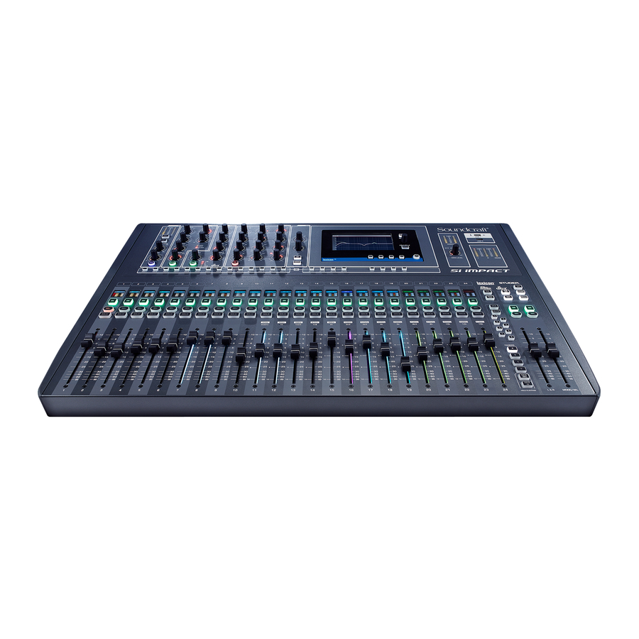
Посмотреть инструкция для Soundcraft Si Impact бесплатно. Руководство относится к категории смесители, 25 человек(а) дали ему среднюю оценку 8.4. Руководство доступно на следующих языках: английский. У вас есть вопрос о Soundcraft Si Impact или вам нужна помощь? Задайте свой вопрос здесь
Не можете найти ответ на свой вопрос в руководстве? Вы можете найти ответ на свой вопрос ниже, в разделе часто задаваемых вопросов о Soundcraft Si Impact.
Как лучше всего выполнять чистку смеситель?
Для удаления отпечатков пальцев лучше всего использовать слегка влажную салфетку для уборки или мягкую чистую ткань. Пыль в труднодоступных местах лучше всего удаляется потоком сжатого воздуха.
Инструкция Soundcraft Si Impact доступно в русский?
К сожалению, у нас нет руководства для Soundcraft Si Impact, доступного в русский. Это руководство доступно в английский.
Не нашли свой вопрос? Задайте свой вопрос здесь

- Manuals
- Brands
- SoundCraft Manuals
- DJ Equipment
- Si Impact
- User manual
-
Contents
-
Table of Contents
-
Bookmarks
Quick Links
®
User Guide
For Soundcraft Si Impact Console
®
Related Manuals for SoundCraft Si impact
Summary of Contents for SoundCraft Si impact
-
Page 1
® User Guide For Soundcraft Si Impact Console ®… -
Page 2
Soundcraft is a trading division of Harman International Industries Ltd. Information in this manual is subject to change without notice and does not represent a commitment on the part of the vendor. Soundcraft shall not be liable for any loss or damage whatsoever arising from the use of information or any error contained in this manual. No part of this… -
Page 3: Table Of Contents
User Manual CONTENTS CONTENTS 1.0 AN INTRODUCTION TO Si IMPACT 7.0: DSP Elements 7.1: Function Focus 1.1: Safety 7.2: ACS / Channel Strip Elements 1.2: Warranty 7.2.1: ACS Input 1.3: Specifications 7.2.2: ACS Gate 7.2.3: ACS Compressor 2.0: GETTING STARTED 7.2.4: ACS Equaliser 2.1: Console Overview 7.2.5: ACS Output 7.3: Control Channel 2.2: Parts Of The Console 7.4: Graphic EQ (GEQ). 2.3: FaderGlow 8.0: MIX FEATURES 3.0: ASSIGNABLE CONTROLS 8.1: Mute Groups 3.1: Fader Layers 8.2: VCA Groups…
-
Page 4: User Manual
1.0: INTRODUCTION INTRODUCTION TO PERFORMER The Soundcraft Si impact is a compact digital console optimised for live sound. It’s powerful, yet simple to use, with intuitive controls, consistent colour-coded feedback, and rapid parameter access. Features such as analogue, MADI, and USB I/O as standard, motorised faders, the Assignable…
-
Page 5: Safety
This unit is capable of operating over a range of mains voltages as marked on the rear panel. The internal power supply unit contains no user serviceable parts. Refer all servicing to a qualified service engineer, through the appropriate Soundcraft dealer. 1.1: INTRODUCTION > SAFETY…
-
Page 6
Soundcraft dealer. • It is recommended that all maintenance and service on the product should be carried out by Soundcraft or its authorised agents. Soundcraft cannot accept any liability whatsoever for any loss or damage caused by service, maintenance or repair by unauthorised personnel. -
Page 7
User Manual 1.1: SAFETY INTRODUCTION > SAFETY WARNINGS ADVICE FOR THOSE WHO PUSH THE BOUNDARIES Although your new console will not output any sound until you feed it signals, it has the capability to produce sounds which, when monitored through an amplifier or headphones, can damage hearing over time. -
Page 8
Equipment or the defective component should be returned to the Dealer or to Soundcraft and subject to the following conditions the Dealer or Soundcraft will repair or replace the defec- tive components. Any components replaced will become the property of Soundcraft. -
Page 9: Specifications
— Storage Temperature Range -20°C to 60°C (-4°F to — User adjustable delay 1sample – 500ms 140°F) — GEQ 31Hz – 16kHz 1/3 octave • — 31Hz – 16KHz 1/3 octave E & OE. Soundcraft reserves the right to change specifications without notice. 1.3: INTRODUCTION > SPECIFICATIONS…
-
Page 10: Getting Started
STARTING OFF — AN INTRODUCTION TO THIS MANUAL Anyone with minimal audio experience should be able to operate the Si Impact console without reading too much of this manual, though we do recommend you take the time to go through it.
-
Page 11
2.1: OVERVIEW GETTING STARTED > OVERVIEW The Si Impact console offers an incredible amount of flexibility and ease-of-use for its relatively compact size. To achieve this, there are several assignable features it is advisable you understand before using the console for performance. -
Page 12: Parts Of The Console
User Manual 2.2: PARTS OF THE CONSOLE GETTING STARTED > PARTS OF THE CONSOLE 2.2: GETTING STARTED > PARTS OF THE CONSOLE…
-
Page 13
User Manual 2.2: PARTS OF THE CONSOLE GETTING STARTED > PARTS OF THE CONSOLE 2.2: GETTING STARTED > PARTS OF THE CONSOLE… -
Page 14: Faderglow
2.3: FADERGLOW GETTING STARTED > FADERGLOW Soundcraft FaderGlow™ is a unique feature that gives the user an additional level of status indication, and can significantly reduce operating errors. Several different functions can be assigned to the console faders, so it can be easy to lose track of which function is currently being controlled, especially when grabbing a fader in a hurry.
-
Page 15: Assignable Controls
3.0: ASSIGNABLE CONTROLS ASSIGNABLE CONTROLS At the heart of the Si Impact is a group of assignable controls that make the console easier and faster to navigate and operate. Assignable controls work by changing the function of sections of the console surface.
-
Page 16: Fader Layers
User Manual 3.1: FADER LAYERS ASSIGNABLE CONTROLS > FADER LAYERS The are four main Fader Layers on the Impact console, selected by the FADERS button group (A, B, C, and D) to the right of the Control Channels. The additional buttons in this group assign Graphic EQ bands across the faders for convenient control.
-
Page 17: Control Channels
User Manual 3.2: CONTROL CHANNELS ASSIGNABLE CONTROLS > CONTROL CHANNELS A Control Channel is an assignable Channel Strip for DSP channels, with Fader, indicators, plus ON, SOLO, and SEL buttons. The SEL button is used to focus the Assignable Channel Strip (ACS) on that channel.
-
Page 18: 1: Control Channel Assignment
User Manual 3.2.1: CONTROL CHANNEL ASSIGNMENT CONTROL CHANNELS > ASSIGNMENT Control Channel Assignment is accessed via the FADER SETUP button in the Touch Screen Main Menu. Select the Control channel using the Fader Layer and SEL buttons in the usual way — the current Fader Bank and Slot Number cannot be edited in the FADER SETUP menu.
-
Page 19
User Manual 3.2.1: CONTROL CHANNEL ASSIGNMENT CONTROL CHANNELS > ASSIGNMENT Assign Stereo Inputs Assign a Stereo Input channel to the currently selected Control Channel. Touching the value field will bring up a scrollable list of available Stereo Input Channel names. Assign Mixes Assign a MIX Master channel to the currently selected Control Channel. -
Page 20
User Manual 3.2.1: CONTROL CHANNEL ASSIGNMENT CONTROL CHANNELS > ASSIGNMENT INSERT BLANK Insert a blank Control Channel into the currently selected Control Channel Slot and shift the others to the left or right. Choosing INSERT BLANK >> (right), for example, will push all Control Channels to the right of the currently selected slot, one slot to the right. -
Page 21: Assignable Channel Strip
User Manual 3.3: ASSIGNABLE CHANNEL STRIP ASSIGNABLE CONTROLS > ACS By pressing the SEL (Select) button on any available DSP channel, you assign that channel’s parameters to the ACS. From the ACS you can control all input, EQ, dynamics, and output functions available to the selected channel.
-
Page 22: Totem (Fader Follow)
User Manual 3.4: tOTEM ASSIGNABLE CONTROLS > tOTEM (FADER FOLLOW) tOTEM (The One Touch Easy Mix) buttons MIX 1-14, MTX 1-4, FX 1-4, situated just below the ACS, make up the FADER FOLLOW button group and allow rapid access to bus contributions from channels in any current Fader Layer.
-
Page 23: Touch Screen Operation
User Manual 4.0: TOUCH SCREEN TOUCH SCREEN The console colour Touch Screen can be used through direct touch, or in conjunction with the Scroll Encoder and MENU / APPLY buttons. It provides access to System settings and preferences, Copy/Paste and cuelist / Show functionality, as well as settings for inputs, outputs monitoring, the solo system, plus a frequency response-type display of the 4-band EQ.
-
Page 24: Main Menu
User Manual 4.1: MAIN MENU TOUCH SCREEN > MAIN MENU The Touch Screen Main Menu can be accessed at any time by pressing the MENU button next to the Touch Screen. From here you can navigate to any of the settings menus. SHOW Show File operations and global Isolate settings, console RESET CONFIG function.
-
Page 25
User Manual 4.1: MAIN MENU TOUCH SCREEN > MAIN MENU SYSTEM System information, HiQnet and IP addressing, selective console reset functions, and the Event Log. Use the system menu to reset channels, busses, patching, and the whole console. See section 11.2 for more detail. PREFS Brightness settings and D.O.G.S. -
Page 26
User Manual 4.1: MAIN MENU TOUCH SCREEN > MAIN MENU Settings and operations for the built in Oscillator. Routing, waveform, frequency, and output options. See section 13 for more detail. MONITOR Settings for the monitoring systems. Delay, patching, and Mono Check. See section 8.5 for more information. INPUTS &… -
Page 27: Inputs & Outputs
DIGITAL IN 1 — 64 & DIGITAL OUT 1-64; the second uses DIGITAL IN 65-96 & DIGITAL OUT 65-96). Both can be used with a wide range of ViSi I/O cards, or a Soundcraft Stagebox (with the MADI card).
-
Page 28: Patching
User Manual 5.1: PATCHING INPUTS AND OUTPUTS > PATCHING When patching an input or output, you will be presented with an I/O selection screen. The current patch is shown with an orange tick over the relevant patch icon. Scroll left or right through the available options and select from the labelled patch icons. The system will only show option cards if they are fitted, or if the show was created on a console with expansion cards fitted, or if the show was created with option cards in the offline editor.
-
Page 29
User Manual 5.1: PATCHING INPUTS AND OUTPUTS > PATCHING Patching for the various inputs and outputs on the console can be accessed as follows: Input Patch Source for an Input Channel. Input Channel selected > INPUTS & VCA menu. Direct Output Patch Direct output from an Input Channel. -
Page 30
User Manual 5.1.1: SOUNDWEB CONTROL INPUTS AND OUTPUTS > PATCHING > SOUNDWEB The console can control BSS Soundweb London devices’ preamp controls via Harman’s HiQnet protocol. When a digital audio transport card (Dante, BLU Link, Cobranet, etc.) is installed and your Si console is connected to a network with Soundweb London devices via the HiQnet port on the back of the console, you can now bring up the SOUNDWEB LONDON EXTERNAL PREAMP control. -
Page 31
User Manual 5.1.1: SOUNDWEB CONTROL INPUTS AND OUTPUTS > PATCHING > SOUNDWEB External Control Status. Disable / Enable Soundweb London Preamp control for this patch. If enabled, this will activate MIC GAIN* and 48V control from the console on that input channel for the associated Soundweb London device. -
Page 32: Default Patching
5.2: DEFAULT PATCHING INPUTS AND OUTPUTS > DEFAULT PATCHING The default patching for the Si Impact console — also shows default Fader Layers in brackets. The console patching can be reset to default via the SYSTEM menu. VCA master assignments are also shown for convenience, though there is no audio patching for these.
-
Page 33
(card 2). The option card outputs are labelled DIGITAL OUT 1-64 (card 1) and DIGITAL OUT 65-96 (card 2). See the Soundcraft Si Option Slot & Option Card User Guide for detailed instructions on card installation and configuration. 5.3 INPUTS & OUTPUTS > ViSi CONNECT… -
Page 34
User Manual 5.3.1: ViSI CONNECT CARDS INPUTS AND OUTPUTS > ViSi CONNECT > CARDS Single Port CAT5 MADI Dual Port CAT5 MADI (redundant link) Dual Port Multi-Mode SC Optical MADI (redundant link) AES 3 XLR (4ch in, 4ch out on XLRs) AES D-Type (8ch in, 8ch out, 25-way D-SUB connector) Multi Digital Card (32 in / 32 out — FireWire for Mac, USB or FireWire for PC, plus 8 in / 8 out ADAT optical). -
Page 35
MADI-USB (32 in/ 64 out MADI + 32 in/out USB, OR 64 in/out MADI + 32 USB out only. Connect Soundcraft Stagebox plus a PC or Mac. See section 5.4 for more detail. 5.3.1: INPUTS & OUTPUTS > ViSi CONNECT > CARDS… -
Page 36: 2: Stageboxes
User Manual 5.3.2: STAGEBOXES INPUTS AND OUTPUTS > ViSi CONNECT > STAGEBOXES Using the fitted MADI-USB card, the Si Impact can be connected to A variety of additional I/O, including the Soundcraft Stageboxes. Soundcraft Mini Stagebox Two variations of a smaller Stagebox for general use when modular I/O is not required.
-
Page 37: Madi-Usb Card
The Soundcraft MADI-USB Combo card offers digital audio connection between an Si series console and Apple Mac or PC with a USB port, as well as any of the Soundcraft range of Stageboxes via Soundcraft’s proprietary Cat 5 MADI connection.
-
Page 38: 1: Madi-Usn Setup
This allows for 32 USB inputs and outputs for PC and Mac recording and playback, plus 32 MADI inputs and 64 MADI outputs (for connec- tion to a Soundcraft Stagebox, for example). DIP Switch 1: Sync — Master / Slave This alters the syncing interaction between the MADI-USB Combo card and the mixer.
-
Page 39: 2: Usb Pc Driver
PC, you will need to restart your machine for the install process to be complete. The Soundcraft Audio Driver settings can be found in the Soundcraft USB Control Panel. Within this menu, there are options to adjust the streaming mode of the MADI-USB Combo Card and the buffer size from 64 samples up to 8192 samples.
-
Page 40: Channels & Busses
6.0: CHANNELS & BUSSES CHANNELS & BUSSES The Si Impact console has several basic channels and busses. These are mono and stereo input channels, mono and stereo Mix Busses and MIX output master channels (MIX 1-14), internal FX send mix busses (FX 1-4), stereo Matrix mix busses and Matrix output master channels (MTX 1-4), and the main Left, Right, and Mono/Centre mix master channels.
-
Page 41: Input Channels
User Manual 6.1: INPUT CHANNELS CHANNELS & BUSSES > INPUT CHANNELS Input channels receive either external input from instruments, microphones, and so on, or they receive input from the internal Lexicon FX units (FX Return — Stereo Input Channels 1-4). Input channels can be mono (64 available: CH 01 — CH 64), stereo (4 available: ST 1 — ST 4 — FX Retunrs by default), or mono-linked (assigned in odd/even stereo pairs of mono Input Channels), and can be patched to any microphone, line, or digital inputs.
-
Page 42
User Manual 6.1: INPUT CHANNELS CHANNELS & BUSSES > INPUT CHANNELS 6.1: CHANNELS & BUSSES > INPUT CHANNELS… -
Page 43: 1: Input Setup
User Manual 6.1.1: INPUT SETUP CHANNELS & BUSSES > INPUT CHANNELS > SETUP There are various input-specific options, found via the Touch Screen Main Menu INPUTS button. These offer channel naming, linking, LR or LCR Panning / routing, Pre/Post routing options for Mix Busses and Direct Outputs, and physical input and Direct Output patching.
-
Page 44
User Manual 6.1.1: INPUT SETUP CHANNELS & BUSSES > INPUT CHANNELS > SETUP LCR Pan Width Set the proportion of centre channel signal sent to Left And RIght. Adjust the pan law when in LCR mode is active to increase/decrease the contributions to the LR and Mono buses when panning. -
Page 45: Mix Outputs
User Manual 6.2: MIX OUTPUTS CHANNELS & BUSSES > MIX OUTPUTS All contributions to a Mix Bus are summed into Mix Bus Master DSP Channels (MIX 1-14). They have various uses, including feeding auxiliary effects, as monitoring mixes, or creating unique mixes for zoned areas, contribution to the main mix, and more.
-
Page 46
User Manual 6.2: MIX OUTPUTS CHANNELS & BUSSES > MIX OUTPUTS 6.2: CHANNELS & BUSSES > MIX OUTPUTS… -
Page 47: 1: Mix Outputs Setup
User Manual 6.2.1: MIX OUTPUTS SETUP CHANNELS & BUSSES > MIX OUTPUTS > SETUP There are various Mix Output-specific options, found via the Touch Screen Main Menu OUTPUTS button. These offer channel naming, isolate, LR / LCR panning and routing Pre/Post routing options, width (stereo/ mono) and physical output patching.
-
Page 48
User Manual 6.2.1: MIX OUTPUTS SETUP CHANNELS & BUSSES > MIX OUTPUTS > SETUP LCR Pan Width Set the proportion of centre channel signal sent to Left And RIght. Adjust the pan law when in LCR mode is active to increase/decrease the contributions to the LR and Mono buses when panning. -
Page 49: Matrix Outputs
User Manual 6.3: MATRIX OUTPUTS CHANNELS & BUSSES > MATRIX OUTPUTS The Matrix busses feed the Matrix Master channels. Matrix Busses can be used for many things, including a convenient way to send the same Mix to several monitor destinations at differing levels; or to use as an alternative main mix of mix groups to feed additional front of house zones.
-
Page 50
User Manual 6.3: MATRIX OUTPUTS CHANNELS & BUSSES > MATRIX OUTPUTS 6.3: CHANNELS & BUSSES > MATRIX OUTPUTS… -
Page 51: 1: Matrix Outputs Setup
User Manual 6.3.1: MATRIX OUTPUTS SETUP CHANNELS & BUSSES > MATRIX OUTS > SETUP There are various Matrix output-specific options, found via the Touch Screen Main Menu OUTPUTS button. These offer naming, isolate, width, and physical output patching. Name Name the selected Matrix Bus. When the Name field is selected, a QWERTY keyboard will appear on the Touch Screen so you can enter the desired name.
-
Page 52: Main Mix Outputs
User Manual 6.4: MAIN MIX OUT CHANNELS & BUSSES > MAIN MIX OUTPUTS The Main Left, Right, and Mono/Centre Busses and Master Channels are used for the main mix output and receive their inputs from the Input Channels and Mix Bus Master channels. The Mono bus is the Centre bus when the Panning Mode of contributing channels is set to LCR, and Mono routing is enabled.
-
Page 53: 1: Main Mix Outputs Setup
User Manual 6.4.1: MAIN MIX OUTPUTS SETUP CHANNELS & BUSSES > MAIN MIX OUTS > SETUP There are various Main LR and M-specific options, found via the Touch Screen Main Menu OUTPUTS button. These offer naming, isolate, and physical output patching. Name Name the selected Main Output Bus.
-
Page 54: Fx Busses
User Manual 6.5: FX BUSSES CHANNELS & BUSSES > FX Busses The FX Send busses (FX 1-4) are used exclusively to feed the internal Lexicon FX units. They receive input from the Input Channels. Those contributions are accessed via the FX 1-4 tOTEM buttons. Management of the Lexicon FX is enabled via the FX button (Lexicon FX setup) near the touch screen.
-
Page 55: Dsp Elements
User Manual 7.0: DSP ELEMENTS CHANNEL ELEMENTS Input and output (Bus Master) DSP channels share many common DSP processing elements and controls via the Control Channel and Assignable Control Section (ACS). This chapter explains those elements and their controls. Please note, some elements will not be available (will be unlit and inactive) on certain channel types (Master Output Channels have no Gate section, for example).
-
Page 56: Function Focus
User Manual 7.1: FUNCTION FOCUS DSP ELEMENTS > FUNCTION FOCUS Function Focus allows pinpoint adjustment of any controls and settings by automatically detailing the value of both the control you are currently adjusting and any other controls in its group, plus the channel name and alternate units for the same control.
-
Page 57
User Manual 7.2: ACS ELEMENTS DSP ELEMENTS > ACS ELEMENTS The Assignable Channel Strip (ACS) follows the currently selected DSP Channel and provides almost all of the controls relating to that. It is broken down into logical sections, making it easy to identify control groups and functions at a glance. -
Page 58: 1: Acs Input
User Manual 7.2.1: ACS INPUT SECTION DSP ELEMENTS > ACS > INPUT The input section mainly provides the features required for input channels such as phantom power and mic/line level. Metering is applicable to all DSP channel types, and HPF (High Pass Filter) is available in Mix Bus Master Channels.
-
Page 59
User Manual 7.2.1: ACS INPUT SECTION DSP ELEMENTS > ACS > INPUT Phase Invert Invert signal phase (180 degrees). Pressing and holding the key will activate Interrogate mode for this function (see Mix Features 8.3). GAIN/TRIM Adjust mic gain or line trim for input channels. The control changes its function depending on the selected input. -
Page 60: 2: Acs Gate
User Manual 7.2.2: ACS GATE SECTION DSP ELEMENTS > ACS > GATE A Gate is a threshold-driven gain reduction process normally used to attenuate a signal when its level falls below the Threshold. Setting the Threshold just above a noise floor or background noise, for example, will allow the Gate to attenuate the source during periods when the main input (voice,…
-
Page 61
User Manual 7.2.2: ACS GATE SECTION DSP ELEMENTS > ACS > GATE DEPTH Adjust the Depth value of the Gate The amount of attenuation applied when the gate is closed. THRESHOLD Adjust the threshold of the Gate The signal level of the sidechain at which the gate is activated. S/C LPF Adjust the Sidechain Low Pass Filter This filter cuts out high frequencies. -
Page 62: 3: Acs Compressor
User Manual 7.2.3: ACS COMPRESSOR SECTION DSP ELEMENTS > ACS > COMPRESSOR A compressor is a threshold driven process used to reduce the dynamic range of a signal by applying gain reduction when the signal level exceeds the threshold and applying ‘make-up gain’…
-
Page 63
User Manual 7.2.3: ACS COMPRESSOR SECTION DSP ELEMENTS > ACS > COMPRESSOR GAIN Adjust the make-up gain of the Compressor Gain applied after the compressor to account for level lost in compression. THRESHOLD Adjust the Threshold level of the compressor When the signal exceeds the threshold, it will be attenuated according to the ratio setting. -
Page 64: 4: Acs Equaliser
User Manual 7.2.4: ACS EQUALISER SECTION DSP ELEMENTS > ACS > EQUALISER The channel EQ (Equaliser) section is used for sculpting the tonal (frequency-based) balance of the signal. The Impact EQ has four fully parametric, full range bands — LF and HF have switchable bell/shelf modes.
-
Page 65
User Manual 7.2.4: ACS EQUALISER SECTION DSP ELEMENTS > ACS > EQUALISER HI MID Level Adjust the boost/attenuation of the HI MID filter. HI MID FREQ Adjust the centre frequency of the HI MID filter. Frequencies above and below this, within the bounds of the Q setting will be affected by the HI MID level control. That is, Q effectively sets the ‘width’… -
Page 66
User Manual 7.2.4: ACS EQUALISER SECTION DSP ELEMENTS > ACS > EQUALISER LO MID Q Adjust the Q of the LO MID Filter Q is ‘magnification’ at resonance, and is inversely proportional to bandwidth. For an equaliser it is useful to think of it simply as a bandwidth control (the width of the ‘bell’… -
Page 67: 5: Acs Output
User Manual 7.2.5: ACS OUTPUT SECTION DSP ELEMENTS > ACS > OUTPUT The outputs section contains features specific to the outputs of all channels. Delay and Pan (or balance) are applicable to all channel types, while LR and MONO/ CENTRE routing is specific to input and Mix Bus Master output channels (not Matrix master channels).
-
Page 68
User Manual 7.2.5: ACS OUTPUT SECTION DSP ELEMENTS > ACS > OUTPUT LR (Main Left Right Bus Routing) Route the selected channel to the Main Left/Right Stereo Bus. Any channels routed to LR will be summed into the Main LR Master Output Channel, controlled by the L&R Control Channel. -
Page 69: Control Channel
User Manual 7.3: CONTROL CHANNEL DSP ELEMENTS > CONTROL CHANNEL Control channels contain the primary performance controls and indicators. Layers of Control Channels (assigned to various ‘actual’ channels) are selected using the FADERS (Fader Layers) button group. Control channel positions are assigned to channels using the Touch Screen FADER SETUP menu (see section 3.2.1).
-
Page 70
User Manual 7.3: CONTROL CHANNEL DSP ELEMENTS > CONTROL CHANNEL Gain Reduction Meter Indicates gain reduction for the selected channel. These are the three LEDs on the left side labelled 1, 5, 10 (dB of attenuation). Level Meter Indicates audio level for the selected channel — dBfs ON key function is dependant on the channel type and selected fader layer. -
Page 71
User Manual 7.3: CONTROL CHANNEL DSP ELEMENTS > CONTROL CHANNEL SOLO Press to Solo this DSP Channel (Input Channel, Mix Bus Master, Matrix Master). See section 8.4 for more information of the console’s Solo system. FADER Adjust signal level. Audio channel / VCA level. FOLLOW MODE (tOTEM button selected): Send level form channel to selected bus. -
Page 72: Graphic Eq (Geq)
User Manual 7.4: GRAPHIC EQ (GEQ) DSP ELEMENTS > GRAPHIC EQ (GEQ) 28-Band Graphic Equalisers (GEQs) are available to all Output Masters on the console: Mix Bus, Matrix Bus, and Left/Right and Mono/Centre Bus Masters. All Masters can run GEQs simultaneously. When any output channel is selected, the GEQ LO and GEQ HI buttons (FADERS button group) will assign 14 bands to the Control Channel Faders, colour-coded with red FaderGlow.
-
Page 73
User Manual 7.4: GRAPHIC EQ (GEQ) DSP ELEMENTS > GRAPHIC EQ (GEQ) GEQ HI Press to assign the 14 ‘high’ GEQ bands (800Hz — 16kHz) to the Control Channel Faders. An output channel (Mix Bus, Matrix Bus, LR / Mono bus masters) must be selected for this button to have any effect. -
Page 74: Mix Features
User Manual 8.0: MIX FEATURES MIX FEATURES Si Impact Mix Features include mix functions outside the normal audio signal path: Mute Groups, VCA Groups, Copy and Paste, Interrogate, the Solo system, Monitoring, and the CLR and ALT + CLR facilities.
-
Page 75: Mute Groups
User Manual 8.1: MUTE GROUPS MIX FEATURES > MUTE GROUPS Mute Groups enable group-muting of selected channels at any time. Create up to eight Mute Groups operated from the Mute/VCA Group Masters button group 1-8. Mute Groups can be cumulative. While not in VCA or MUTE setup modes, the buttons are always Mute Group Masters.
-
Page 76
User Manual 8.1: MUTE GROUPS MIX FEATURES > MUTE GROUPS Select Control Channels. While in Mute Group SETUP mode, with a Mute Group Master active, use the Control Channel SEL buttons to choose which channels should belong to that Mute Group. Orange highlighted SEL buttons indicate members of the currently selected Mute Group. -
Page 77: Vca Groups
User Manual 8.2: VCA GROUPS MIX FEATURES > VCA GROUPS VCA Groups allow you to control groups of Input Channels from a single VCA Master. For example, you could put the whole drum kit under the control of a single VCA Master, or if you have a multiple mics on a guitar cabinet you could set the ratios with individual channels and then create a Guitar VCA Master — move the VCA Master Channel and all Group Member levels will be ‘offset’…
-
Page 78
MIX FEATURES > VCA GROUPS The Si Impact has eight VCA Groups available, setup with the VCA Setup button and the Mute/VCA button Group. Simply press the VCA Setup button, select a VCA Master 1-8, then use the SEL buttons to allocate channels to the group. -
Page 79
User Manual 8.2: VCA GROUPS MIX FEATURES > VCA GROUPS Clear Selection. While in VCA Group Setup mode, holding the CLR button and pressing a VCA Group Master button 1-8 will clear that VCA Group. ALT + CLR Clear all. While in VCA Group Setup mode, holding ALT + CLR and pressing a VCA Group Master Button 1-8 will clear all VCA Groups. -
Page 80: Copy And Paste
User Manual 8.3: COPY AND PASTE MIX FEATURES > COPY AND PASTE This facility allows almost any processing section to be copied easily and quickly from a channel or bus and pasted to another channel or bus. You can also copy and paste the internal Lexicon FX settings and Aux, FX Send, and Matrix mixes.
-
Page 81
User Manual 8.3: COPY AND PASTE MIX FEATURES > COPY AND PASTE DSP Channel COPY-PASTE With a DSP channel (Input Channel or Mix/Matrix Bus Master) selected, COPY PASTE mode will display a version of the ACS (with GEQ for Bus Masters). -
Page 82: Audio Interrogate
User Manual 8.4: AUDIO INTERROGATE MIX FEATURES > AUDIO INTERROGATE Audio Interrogate is a powerful method of checking and changing a particular switch status across all channels on the currently selected fader layer. For example, you can check at a glance which channels are routed to the main LR mix bus and change that status rapidly for all visible channels.
-
Page 83: Solo System
User Manual 8.5: SOLO SYSTEM MIX FEATURES > SOLO SYSTEM Solo provides a way of monitoring and checking individual channels and groups of channels quickly by routing only the ‘soloed’ channels either to the monitoring system (normal operation) or to the main mix outputs (Solo In Place — SIP).
-
Page 84: Solo In Place
User Manual 8.5: SOLO SYSTEM MIX FEATURES > SOLO SYSTEM SOLO Press to solo the assigned channel Normal button behaviour is ‘latching’ (press on — press off). Press and hold a SOLO button for momentary (non-latch- ing) behaviour. Press and hold an active SOLO button to use the Highlight feature, which highlights a soloed channel by attenuating other soloed channels.
-
Page 85
User Manual 8.5: SOLO SYSTEM MIX FEATURES > SOLO SYSTEM Blend Level The attenuation level of the primary monitor source while a PFL or AFL is active. The default setting is -∞ (- infinity) resulting in complete mute of the normal monitor source. Input Priority Allow input Solos to temporarily override an output AFL. -
Page 86: Monitoring
8.6: MONITORING MIX FEATURES > MONITORING The Si Impact monitoring system is comprehensive, yet simple. The monitoring source (active monitor signal) will normally be the main LR mix, though will switch to any selection made in the Solo system — AFL or PFL busses.
-
Page 87
User Manual 8.6: MONITORING MIX FEATURES > MONITORING Monitoring Settings Menu You access the Monitor Settings menu by touching the MONITOR Touch Screen button from the Main Menu. L&R Monitor Speaker Enable / disable the Monitor Output patch. Patching for the monitor output is specified in the separate Monitor L&R OutPatch menu item below. Mono Check Outputs a mono sum of the stereo monitor signal. -
Page 88: Clr & Alt+Clr
User Manual 8.7: CLR & ALT+CLR MIX FEATURES > CLR & ALT+CLR The CLR (Clear) button located to the right of the Channel Faders area is used in conjunction with individual input channels, output channels, channel parameters, and mutes to clear or reset to default.
-
Page 89
User Manual 8.7: CLR & ALT+CLR MIX FEATURES > CLR & ALT+CLR CLR + GEQ HI/LO (FADERS) Reset all Graphic EQ levels to 0dB for the currently selected channel. Only works where GEQ is available (output / bus channels). CLR + tOTEM (FADER FOLLOW) button Reset all contributions and ON status from channels or buses to the selected bus back to factory defaults. -
Page 90
User Manual 8.7: CLR & ALT+CLR MIX FEATURES > CLR & ALT+CLR ALT + CLR + Any MIX tOTEM button (MIX 1-14) Resets all channels’ contributions to all 14 Mix busses to zero. It Does not affect the Auxiliary Mix bus master channels or master levels. -
Page 91: Shows, Cuelists, And Snapshots
User Manual 9.0 SHOWS, CUELIST, SNAPSHOTS SHOWS, CUELIST, AND SNAPSHOTS The console file system uses the Show as it’s basic file. The Show contains all console settings, plus the Cuelist. The Cuelist contains recallable Cues that contain Snapshots of console settings, plus automation functionality (HiQnet events).
-
Page 92: Shows
User Manual 9.1 SHOWS SHOWS, CUELIST, SNAPSHOTS > SHOWS A Show is an entire console setup including Cuelist and associated Snapshots. Shows can be saved, loaded, and created in the EDIT SHOW Touch Screen Menu. You can also reset the I/O configuration of the console through the EDIT SHOW Touch Screen Menu.
-
Page 93
Clears the console database of any option cards or external I/O systems that may have been attached to the console then forces a ‘re-discovery’ of any installed option cards or connected I/O system, such as a Soundcraft Stagebox. The system will provide a warning that the action will overwrite the current configuration database and allow the action to be aborted. -
Page 94: Cuelist & Snapshots
User Manual 9.2: CUELIST & SNAPSHOTS SHOWS, CUELIST > CUELIST & SNAPSHOTS The Si Impact incorporates a comprehensive Cuelist and Snapshot automation system for fast access to preset console states and for working with other performance systems via Harman’s HiQnet.
-
Page 95: Cue List
User Manual 9.2: CUELIST & SNAPSHOTS SHOWS, CUELIST > CUELIST & SNAPSHOTS CUE LIST Bring up the Cuelist screen in the console Touch Screen. This gives access to Cuelist editorial, and Cue editing functionality. There are four columns in the main Cuelist: Cue Number, Snapshot Name, and HiQnet Status.
-
Page 96
User Manual 9.2: CUELIST & SNAPSHOTS SHOWS, CUELIST > CUELIST & SNAPSHOTS UPDATE Update the currently active Cue with the current Snapshot. Useful for editing Cues as they are used. When you press UPDATE confirmation will be required in the Touch Screen as the action will overwrite the current Cue. -
Page 97
User Manual 9.2: CUELIST & SNAPSHOTS SHOWS, CUELIST > CUELIST & SNAPSHOTS HiQnet Status Highlighted orange if there is an active HiQnet transmit active in the Cue. 9.2: SHOWS, CUELIST > CUELIST & SNAPSHOTS… -
Page 98: 1: Edit Cue
User Manual 9.2.1: EDIT CUE SHOWS, CUELIST > CUELIST > EDIT CUE By touching the EDIT CUE Touch Screen button in the Cue List display you access more detail, in- cluding the Cue Name, and HiQnet automation parameters. HiQnet is a network protocol, developed by Harman Pro for communications and control between audio system components.
-
Page 99: Lexicon Fx
User Manual 10: LEXICON FX LEXICON FX The console comes with four Lexicon FX processors, each with 29 available algorithms. Each FX unit has its own dedicated FX Send Bus, and stereo return path. Send Routing Every input channel can contribute to the FX 1-4 send busses, which correspond to the FX unit 1-4 inputs. Contributions are controlled in the same way as Mix bus contributions, via the FX 1 — 4 tOTEM buttons, which assigns each channel’s contribution to the selected bus to its fader.
-
Page 100
User Manual 10: LEXICON FX LEXICON FX Storage All Parameters from the four FX Units and for all FX Types are stored with console Snapshots. See chapter reference 9.2 for more on the Cuelist and Snapshots. Copy Paste Settings can be copied and pasted between processors using the console COPY PASTE function. Touch COPY PASTE in the Touch Screen Main Menu, then press the FX button in the Lexicon control group. -
Page 101: Reverbs
User Manual 10.1: REVERBS LEXICON FX > REVERBS Reverberation (or “reverb” for short) is the complex effect created by the way we perceive sound in an enclosed space. When sound waves encounter an object or boundary, they don’t just stop. Some of the sound is absorbed by the object, but most of the sound is reflected or is diffused.
-
Page 102: Room Reverb
User Manual 10.1: REVERBS LEXICON FX > REVERBS Room Reverb Room produces an excellent simulation of a very small room which is useful for dialogue and speech applications. Room is also practical when used judiciously for fattening up high energy signals like electric guitar amp recordings. Ambience Reverb Ambience is used to simulate the effect of a small or medium sized room without noticeable decay.
-
Page 103: 1: Reverb Parameters
User Manual 10.1.1: REVERB PARAMETERS LEXICON FX > REVERBS > REVERB PARAMETERS PRE DLY — Pre Delay Adjust time delay between the source signal and the onset of reverberation. This control is not intended to precisely mimic the time delays in natural spaces, as the build-up of reverberation is gradual, and the initial time gap is usually relatively short.
-
Page 104
User Manual 10.1.1: REVERB PARAMETERS LEXICON FX > REVERBS > REVERB PARAMETERS Shape Adjust the ‘contour’ of the reverberation envelope. With Shape all the way down, reverberation builds explosively, and decays quickly. As Shape is advanced, rever- beration builds up more slowly and sustains for the time set by Spread. With Shape in the middle, the build-up and sustain of the reverberation envelope emulates a large concert hall (assuming that Spread is at least halfway up, and that Size is 30 meters or larger). -
Page 105: Delays
User Manual 10.2: DELAYS LEXICON FX > DELAYS Delays repeat a sound a short time after it first occurs. Delay becomes echo when the output is fed back into the input (feedback). This turns a single repeat into a series of repeats, each a little softer than the last. Studio Delay The Studio Delay features up to 1 second of stereo delay and offers a built-in ducker that attenuates the delay output whenever signal is present at the input.
-
Page 106: 1: Delay Parameters
User Manual 10.2.1: DELAY PARAMETERS LEXICON FX > DELAYS > DELAY PARAMETERS Dly Time — Delay Time Controls the length of the delay time relative to Tempo. At the middle of its range, delay repeats are synchronous with the Tempo button; lower values create faster repeats, while higher values increase the time between repeats.
-
Page 107
User Manual 10.2.1: DELAY PARAMETERS LEXICON FX > DELAYS > DELAY PARAMETERS Smear Ducking attenuation amount. Available only for Tape and Reverse Delays, this parameter controls the amount of “smear,” or signal degradation and frequency loss. The higher the setting, the more each delay repeat loses intelligibility compared to the original signal. -
Page 108: Misc Fx
User Manual 10.3: MISC FX LEXICON FX > MISC FX The MISC category provides primarily modulated and pitch-varying effects. Chorus Chorus creates a lush, full sound by combining two or more signals together where one is unaffected and the other signals vary in pitch very slightly over time.
-
Page 109: 1:Misc Fx Parameters
User Manual 10.3.1: MISC FX PARAMETERS LEXICON FX > DELAYS > DELAY PARAMETERS Speed Sets the speed at which the modulated effect cycles. Depth — LFO Depth Scales the intensity of the effect. This control affects the output of the LFO only. It has no effect on the outputs of the individual waveforms. Voices — Number Of Voices Controls the number of additional Chorus voices.
-
Page 110
User Manual 10.3.1: MISC FX PARAMETERS LEXICON FX > DELAYS > DELAY PARAMETERS Waveform Selects the wave pattern used by the modulated effect. Select from sine wave, triangle wave, Stepped Triangle, and random. Phase Controls whether amplitude or depth change occurs in both left and right outputs simultaneously or alternates between left and right outputs. -
Page 111
User Manual 10.3.1: MISC FX PARAMETERS LEXICON FX > DELAYS > DELAY PARAMETERS Rot Max Sets the maximum speed at which the LF Speaker will rotate. Rotary effect only: The speed limits are used when the speed parameter is changed from Slow to Fast. Horn Min Rotary effect only: Minimum speed of the HF rotary horn. -
Page 112
User Manual 10.3.1: MISC FX PARAMETERS LEXICON FX > DELAYS > DELAY PARAMETERS Fdbk ‘n’ — Feedback Adjusts how much of the shifted signal is sent back through the delay line in Pitch Shift and De- tune. For creating cascading arpeggio-type effects. Pan ‘n’ Sets the pan position in the stereo field for each tap in the 2-Tap Delay or each channel of the pitch shift/detune effects. -
Page 113: Preferences, System, Security
User Manual 11.0: SETTINGS, SOFTWARE, RESET SYSTEM SETTINGS System Settings are accessed via the Touch Screen Main Menu and appear under the Menus PREFERENCES, SYSTEM, and SECURITY. 11.1: Preferences (PREFS) The PREFS Menu is mainly concerned with LED and LCD (display, buttons etc) brightness and adjustments.
-
Page 114
User Manual 11.1: PREFERENCES SETTINGS > PREFERENCES Preferences include console brightness settings and the D.O.G.S. (Direct Out Gain Stabiliser) system enable. LED Brightness Adjust the brightness of LEDs across the console. This includes all Encoder level indicators, metering, and status LEDs. FaderGlow Brightness Adjust the FaderGlow brightness across the console. -
Page 115
User Manual 11.1: PREFERENCES SYSTEM SETTINGS > PREFERENCES Channel LCD Contrast Adjust the contrast of the Control Channel LCD screens. D.O.G.S. Enable / Disable Direct Out Gain Stabiliser system. D.O.G.S. is a tool that prevents Direct Output levels from changing when a Mic Gain is changed — so any feeds taken from the console remain stable. -
Page 116
User Manual 11.2: SYSTEM MENU SYSTEM SETTINGS > SYSTEM MENU The System menu provides information about the console itself, as well as offering settings for the console name, date, time, wordclock, and network settings (for HiQnet and Soundweb functionality). The System Menu also provides reset functions for channels, busses, patching, and ‘all’, as well as the Event Log. -
Page 117: Event Log
User Manual 11.2: SYSTEM MENU SYSTEM SETTINGS > SYSTEM MENU RESET ALL Reset all parameters including names and patches to factory default. You will be asked to confirm this action in the Touch Screen. EVENT LOG A log of specific system events. Can be useful for trouble shooting and for technical support staff.
-
Page 118: Subnet Mask
User Manual 11.2: SYSTEM MENU SYSTEM SETTINGS > SYSTEM MENU Time System Time. Touch or select to bring up a time editor in the Touch Screen. Wordclock Choose an Internal, External, or Option card wordclock reference. The console can be set as Word Clock Slave (EXTernal or OPTION) or Master (INTernal). When set to EXTernal the console will attempt to clock from an incoming word clock to the rear panel Word Clock connection.
-
Page 119
User Manual 11.2: SYSTEM MENU SYSTEM SETTINGS > SYSTEM MENU HiQnet Enabled/Disabled Turn HIQnet capability On of Off. This console can transmit HiQnet Venue Events on the network along with cue recalls. Please see chapter ref- erence 9.2 for more detail. The console can also control Soundweb London Device Pre amp devices directly via HiQnet — see chapter reference 5.1.1 for more detail. -
Page 120
User Manual 11.3: SECURITY MENU SYSTEM SETTINGS > SECURITY MENU This console can be set to allow specific access privileges to a number of users. You can lock-out a variety of console functions, as defined in User Profiles. When LOCK is set in the Security menu, a user selection and valid password are required to operate the console. -
Page 121
User Manual 11.3: SECURITY MENU SYSTEM SETTINGS > SECURITY MENU DELETE USER Delete the selected User. The system will ask for confirmation in the Touch Screen to confirm this action. PROFILES Access the Profiles Menu. Use the Profiles Menu to add and edit profiles that can be assigned to users. LOCK Lock the console. -
Page 122: 1: Add/Edit User
User Manual 11.3.1: ADD / EDIT USER SYSTEM SETTINGS > SECURITY > ADD / EDIT USER The Add and Edit User menus require similar information — User Name, Profile, and Password. Profiles can be created and/or edited in the Edit Profile menu (see chapter reference 11.3.2 for more detail).
-
Page 123
User Manual 11.3.1: ADD / EDIT USER SYSTEM SETTINGS > SECURITY > ADD / EDIT USER CANCEL Cancel the current User creation or edit without saving any altered values. SAVE Save the current User. 11.3.1: SETTINGS > SECURITY > ADD / EDIT USER… -
Page 124: 2: Profiles
User Manual 11.3.2: PROFILES SYSTEM SETTINGS > SECURITY > PROFILES A profile defines the access privileges of a console User. Many functional aspects of the console can be denied to users, according to the Profile. The access categories are: Input Processing, Bus Sends, Bus Processing, Matrix Sends, Matrix Processing, Main Output Processing, Main Output Matrix Sends, Main Output On Faders, GEQ, Fader Layer A, Fader Layer B, Fader Layer C, Fader Layer D, FX, Touch Screen, and Cue List.
-
Page 125
User Manual 11.3.2: PROFILES SYSTEM SETTINGS > SECURITY > PROFILES CANCEL Cancel the current Profile creation or edit without saving any altered values. SAVE Save the current Profile. Profile Select a profile to view or edit. Touch or select the value field to select a Profile. You can only edit profiles when logged on as the Administrator. 11.3.1: SETTINGS >… -
Page 126: Software Updates
11.4: SOFTWARE UPDATE SYSTEM SETTINGS > SOFTWARE UPDATE The Si Impact software is updated via the USB data port on the front panel. Details and special instructions for any release will be included with the software release package; however, the ‘normal’…
-
Page 127: Reset Console
User Manual 11.5: RESET CONSOLE SYSTEM SETTINGS > RESET CONSOLE The following procedure will restore the console back to the factory defaults and re-format the internal SD card. DO NOT do this is you wish to keep saved data (Shows). You can use the RESET options in the SYSTEM menu to set parameters and settings back to factory default without destroying data.
-
Page 128: Oscillator
User Manual 12: OSCILLATOR OSCILLATOR The console’s internal Oscillator is a signal generator provided for various test purposes. It can generate either a sine wave or pink noise (equal power per octave) and has various routing options to Mix and Matrix busses, as well as a patchable physical output. It is not possible to route directly to the console’s LR and MONO buses, though you can route the Oscillator signal to a Mix bus master then use the LR and MONO routing keys.
-
Page 129
User Manual 12: OSCILLATOR OSCILLATOR Frequency Set the frequency for the Oscillator’s Sine output. Type Set the signal type for the Oscillator output. Either Sine Wave or Pink Noise (Full spectrum, equal power per octave). Oscillator Out Patch Set a physical output for the Oscillator signal Touching or selecting the value field will bring up a normal patching screen in the Touch Screen. -
Page 130: Appendix 01: No Sound
User Manual APPENDIX 01: NO SOUND? NO SOUND? A Troubleshooting Guide. One of the most common problems experienced with mixing consoles is finding that an input isn’t ap- pearing at an output. There are many possible reasons for this, but the best way to troubleshoot it is to first make sure the Control Channel is set up correctly, then to go through the signal path and workout where the ‘break’…
-
Page 131
User Manual APPENDIX 01: NO SOUND? NO SOUND? Is the Gate shut? It is possible for an incorrectly set Gate process to stop all signal. This happens most often when the threshold is set too high and the signal never gets loud enough to ‘open’ the Gate. You can easily check this by turning the Gate process off with the GATE button in the GATE section of the ACS (7.2.2). -
Page 132
User Manual APPENDIX 01: NO SOUND? NO SOUND? Is the Signal Routed to a valid output bus or channel? Routing can cover LR and Mono routing, as well as Mix bus routing. This will depend on the particular instance. If the issue is no output at the main LR or mono outputs for example, then check than the signal is routed using the LR and/or MONO buttons in the ACS OUT section (7.2.5).
-
#1
Всем привет!
На днях стал обладателем данного пульта.
Одна из последних версий серии SI
- 32 аналоговых микрофонных/линейных входа;
- восемь из них, выполненных на комбинированных разъёмах XLR + TRS, можно использовать в качестве инструментальных входов;
- 40 входных каналов DSP (32 моно входа и 4 стереоканала/возврата);
- 31 выходная шина (все с полной DSP-обработкой и GEQ);
- полностью параметрический 4-полосный эквалайзер на каждый канал и шину;
- восемь VCA-групп и столько же Mute-групп;
- 26 моторизованных фейдеров (24 поканальных входных и два фейдера LR/Mono);
- четыре полностью настраиваемые Fader Layers;
- имеется возможность подключения стейджбокса;
- цветной сенсорный ЖК-дисплей диагональю 5 дюймов;
- цветные индикаторы Channel Displays для каждого входного фейдера;
- 4 процессора эффектов студийного качества Lexicon и выделенные FX-шины;
- графические эквалайзеры BSS на каждую шину;
- двадцать sub-групп/AUX-шин;
- 4 матричные шины моно/стерео;
- звуковой интерфейс 32×32 для записи и воспроизведения мультитрека;
- возможность дистанционного управления с помощью iPad, на котором установлено приложение ViSi Remote.
-
#2
До этого момента не имел дела с цифровыми микшерами.
И столкнулся с такой проблемой. По usb веду подорожечную запись с микшера в DAW (2 микрофона), однако звук из мониторов не идет при воспроизведении трека из программы.
Мониторы подключены к 15 и 16 выходным каналам. Настройки на микшере умолчательные, кроме назначенных каналов для записи по usb.
Но в мониторах тишина. Нужно как-то приписывать маршрут, откуда будет идти звук?
-
#3
@Alfiks, ну выход из компа назначте на какие нибудь входа
-
#4
Как заставить сей микшер выводить звук из daw. Записываю дорожки нормально, но проиграть через микшер не могу. Какой канал указать в daw на воспроизведение. Как его сконфигурировать в микшере?

sunet
Victor Buruiana, 1959
-
#5
На днях на концерте работала группа с таким пультом. На вид невзрачный, но звук нормальный, возможности богатые, удобный, а цена и вовсе шокирует…!
-
#6
На вид невзрачный, но звук нормальный, возможности богатые, удобный
Тоже приходилось работать на Si Expression, но по звуку лично мне как-то не пришёлся. Обработки по качеству средненькие, на моё ухо.
Касательно автора темы: странно, что @Alfiks целый год, практически, искал роутинг пульта, тогда как у производителя есть официальный русский мануал. Я, перед работой на оном пульту, нашёл быстро руководство, т.к. местный персонал понятия не имел, как с этим пультом управляться.
-
#7
Я вернулся )))
Подскажите как завести внешнюю обработку в микшер? Обычно есть вход инсерт, но тут пульт цифровой, и не понятно как его настроить.
По помему нубскому мнению нужно заводить инструмент в обработку, а потом из обработки в микшер. Но если мне не нужно все время его использовать, как его отключить? Не перевтыкать же входы-выходы каждый раз из устройств.
sunet
Victor Buruiana, 1959
-
#8
Так в цифровых пультах на каждом канале внутренняя обработка, для чего их в первую очередь и берут, чтоб избавится от всех внешних кабелей и рэков.
-
#9
Согласен. Но не всегда хватает того, что есть… А со временем хочется бОльшего.
-
#10
@Alfiks, а что за внешнюю обработку хотите использовать?
-
#11
Лексикон 400 серии, Universal Audio LA-610 MKII и халявный TL Audio 5052 Ivory 2.
-
#12
Universal Audio LA-610 MKII и халявный TL Audio 5052 Ivory 2.
Эти два прибора перед пультом нужно задействовать, т. е прямо в них втыкаете микрофоны, а с их выходов сигнал отправляете дальше во входной канал пульта. Lexicon разумнее использовать как сенд\ретюрн эффект, чтобы можно было обработать им сразу несколько каналов, допустим все вокальные микрофоны. В первом случае никакой дополнительной маршрутизации в пульте не требуется, во втором нужно организовать посылы\ возвраты внутри пульта. Допустим делаете сенд c нужного вам канала на Aux, а этот самый Aux назначаете на физический выход пульта. C этого физического выхода сигнал идет прямо во вход лексикона, а выходные каналы лексикона заводите на любые входные каналы пульта. Эти входные линейки и будут вашими ретюрн (возвратами).
Хотя не совсем понятно, что вы хотите делать при помощи LA-610 MKII и TL Audio 5052 Ivory 2, может организовать параллельную компрессию? Опишите подробнее чего вам нужно, то от этих приборов? Вариантов использования может быть как минимум два.
-
#14
А что есть другая, или я просто не знаю?
-
#15
LA-610 MKII пойдет на голос, а TL Audio 5052 Ivory 2 пущу на гитару и/или барабаны
Допустим делаете сенд c нужного вам канала на Aux, а этот самый Aux назначаете на физический выход пульта.
Так вот вопрос, выход в моем случае OUTPUTS? Пока применение я нашел им при использовании подгрупп.
-
#16
И еще вопросик, можно ли используя MADI интерфкейс поключиться к оптическому входу/выходу на 8 канальной карточке фокусрайт? Существуют в природе такой кабель переходник?
Спасибо.
-
#17
@Radiator, ну если mx может все же не стоит, обработка там так себе, в пульте то как минимум не хуже
-
#18
@Radiator, ну если mx может все же не стоит, обработка там так себе, в пульте то как минимум не хуже
Если не хуже, но их больше намного, да и девайс есть. А лексикон MX400XL
-
#19
Если не хуже, но их больше намного, да и девайс есть.
Нифига не понял, что не хуже чего? Где чего больше намного? Абракадабра какая-то!
Так вот вопрос, выход в моем случае OUTPUTS? Пока применение я нашел им при использовании подгрупп.
Выход не тлоько в вашем случае OUTPUT, он в любом случае выход. Применение физическим выходам цифрового пульта можно найти для любых выходных шин, будь то AUX, SubGroup, Master или Matrix.
LA-610 MKII пойдет на голос, а TL Audio 5052 Ivory 2 пущу на гитару и/или барабаны
Ну значит и втыкайте один микрофон в LA-610 MKII, сигнал с гитары в первый вход TL Audio 5052 Ivory 2, а второй вход Ivory 2 оставьте для барабанов, если не смущает, что оверхеды будут моно. Вы объясните, как и для чего вам второй вход ivory? Для параллельной компрессии барабанов, или как?
Последнее редактирование:
-
#20
Нифига не понял, что не хуже чего? Где чего больше намного? Абракадабра какая-то!
Ну мы же сравниваем с возможностями микшера, в котором только 4 эффекта. Сомневаюсь что в микшер поставили эффекты сравнимые с pcm96. Да и рулежка с ПК дает определенное удобство.
На счет выходов спасибо за поянение. Буду разбираться.
Что касается Ivory 2, его применения, можно и для барабанов использовать, а потом отдельно записать гитару. Пока не знаю. Недавно только достался он мне.
@Radiator, С наступившим кстати вас новым годом. Что-то вы на форуме тут сидите, помогаете, в то время как другие все в гульках )))
-
#21
@Alfiks, а почему вы сомневаетесь, саундкрафт как и лексикон это одна контора, там давно вся обработка на основе лекса.
И тем более что в брошуре к этому пульту нарисован 400 лекс. И параметров судя мануала регулируется очень много
Последнее редактирование:

-
#22
Хоспади, ды нормальные в этом пульте ревера, как минимум, соответствует классу микшера.
4fx стереофонические шины с нормальной регулировкой всех необходимых параметров.
ХЗ зачем такой гибрид городить с кучей ADC-DAC преобразований ради посредственного ревера, который точно не лучше интегрированных в пульт.
-
#23
@Alexey Makov, ну четырех эффектов встроенных все-таки маловато, почему бы не использовать внешний ревербератор? Тем более свободных входов, выходов более чем достаточно для группы. Насчет ревера, нормальный он, чем-то даже по характеру lexicon 300 напоминает.
Что касается Ivory 2, его применения, можно и для барабанов использовать, а потом отдельно записать гитару. Пока не знаю. Недавно только достался он мне.
А ну так вам для студии чтоли? Тогда используйте эти приборы для чего хотите, тем более если запись раздельная.
Последнее редактирование:
-
#24
@Alexey Makov, ну четырех эффектов встроенных все-таки маловато, почему бы не использовать внешний ревербератор?
Мало? Можете описать типичную вашу задачу в концертной практике, где мало 4fx-шин?
-
#25
@Alexey Makov, ну я лично использую гораздо больше, все от группы зависит. В том же Behringer X32, Allen Heath iLive и то восемь эффект процессоров. Ведь иногда хочется использовать какой-нибудь эффект в инсертах каналов, допустим транзиент шейпер или динамический эквалайзер, эксайтер и т. д. Как правило это два ревера (вокалы, малый барабан) Два дилея часто, один быстрый второй меденный на какие-нибудь повторы фраз. Уже четыре получаем, а хочется еще дин. экв. на вокал, транзиент дизайнер на бочку, малый (хотя тут можно и компрессорами канальными заморочиться) На лайве еще очень выручает иногда эксайтер на мастере, с чуть-чуть.
Вообще ТС запись интересует, тогда я бы вообще не стал пользоваться встроенной обработкой пульта (разве что для мониторинга музакантам), зачем этот гемморой? Лучше записать наиболее чисто и потом в коробке месить.
Последнее редактирование:
-
#26
Короче, пошла путаница между последовательной и параллельной обработкой. Между назначаемыми эффектами и FX-шинами.
@Alexey Makov, ну четырех эффектов встроенных все-таки маловато, почему бы не использовать внешний ревербератор? Тем более свободных входов, выходов более чем достаточно для группы.
@Alexey Makov, ну я лично использую гораздо больше, все от группы зависит. В том же Behringer X32, Allen Heath iLive и то восемь эффект процессоров. Ведь иногда хочется использовать какой-нибудь эффект в инсертах каналов, допустим транзиент шейпер или динамический эквалайзер, эксайтер и т. д. Как правило это два ревера (вокалы, малый барабан) Два дилея часто, один быстрый второй меденный на какие-нибудь повторы фраз. Уже четыре получаем, а хочется еще дин. экв. на вокал, транзиент дизайнер на бочку, малый (хотя тут можно и компрессорами канальными заморочиться) На лайве еще очень выручает иногда эксайтер на мастере, с чуть-чуть.
Сабжевый пульт позволяет штатно использовать 2 ревера+2дилея, а вот перечисленные «улучшайзеры» в инсерте а-ля Х32 у него не предусмотрены по архитектуре(ну кроме штатных eq-gate-comp на ячейках). И никакими доп.средставми не получится это прицепить. Ну если только через AUX а-ля Direct Out отправить, внешними средствами полирнуть и вернуть на свободный канал. Но это еще те «50 оттенков …». С такими амбициозными задачами лучше изначально другой пульт иметь.
Последнее редактирование:
sunet
Victor Buruiana, 1959
-
#27
Кто постоянно пользуется этим пультом? Видел у ребят, да и по описанию и органам управления мне он кажется наверное самым удобным и оперативным для живой работы. Цена вообще вне конкуренции. Вопрос — как он вам в практической работе, по звуку и насколько он надежен?
sunet
Victor Buruiana, 1959
-
#28
И еще — есть ли у него спектроанализатор который накладывается на экране на EQ? Привык к этой удобной функции в M32.
-
#29
Здравствуйте.
Подскажите, пожалуйста, как на нём сделать честное стерео с двух «микрофонных» входов? В меню стерео назначается только на LEX-RT, а его, в свою очередь, уже не удаётся прикрепить к входным XLR-кам И непонятно, как привязывать всё это на выходные L-R.
С Vi1000 разобрался минут за 30 по инструкции. Тут ни в какую…
Или следующий путь будет верным?
По тестам с офлайн редактором:
первый вход сажаем на mix1 (второй снимаем),
второй вход сажаем на mix2 (первый снимаем),
на mtx1 сажаем mix1 и пускаем на L&R,
на mtx2 сажаем mix2 и пускаем на RIGHT,
прокатит?
Последнее редактирование: