- Manuals
- Brands
- SPERONI Manuals
- Water Pump
ManualsLib has more than 563 SPERONI Water Pump manuals
Click on an alphabet below to see the full list of models starting with that letter:
2
A
C
E
G
H
K
M
N
P
R
S
T
V
Popular manuals
68 pages
CAM 40/22 Operating Instructions Manual
25 pages
CS Series Operating Instructions Manual

17 pages
SP-SX Operating Instructions Manual
64 pages
CAM 40 Operating Instructions Manual
68 pages
CAM 40 Operating Instruction
40 pages
SVM 90 BR Instruction Manual
68 pages
CAM 60 Operating Instructions Manual
68 pages
CAM 75 Operating Instructions Manual
33 pages
ECM-ECT/D Instruction Manual
21 pages
CFM Operating Instructions Manual

21 pages
APM 75 Operating Instructions Manual
6 pages
ECO LIFT WC 560 Instruction Manual

52 pages
VS Operating Instructions Manual

28 pages
RSM Operating Instructions Manual
29 pages
SVM 100 Instruction Manual
24 pages
SCM Series Operating Instructions Manual
57 pages
MATIC Series Operating Instructions Manual

21 pages
CAM 40 Operating Instructions Manual
20 pages
HGM Operating Instructions Manual
32 pages
SCX Operating Instructions Manual
Models
Document Type
2
2CM

Operating Instructions Manual • Operating Instructions Manual
A
AGC 1100/25
Operating Instructions Manual
AGC 800/22
Operating Instructions Manual
AKC
Operating Instructions Manual
AKM
Operating Instructions Manual
AMP 1104/25
Operating Instructions Manual
APM 100
Operating Instructions Manual
APM 100/25
Operating Instructions Manual
APM 200/25
Operating Instructions Manual
APM 75
Operating Instructions Manual
AXC 1100/22
Operating Instructions Manual
AXC 1100/25 X
Operating Instructions Manual
AXC 800/22
Operating Instructions Manual
C
CAM 100
Operating Instructions Manual • Operating Instruction • Operating Instructions Manual • Operating Instructions Manual • Operating Instructions Manual • Operating Instructions Manual
CAM 100 HL
Operating Instructions Manual • Operating Instruction • Operating Instructions Manual
CAM 100 PA
Operating Instructions Manual • Operating Instruction • Operating Instructions Manual • Operating Instructions Manual • Operating Instructions Manual • Operating Instructions Manual
CAM 100/25
Operating Instructions Manual
CAM 100/25 HL
Operating Instructions Manual
CAM 100/60
Operating Instructions Manual
CAM 130
Operating Instructions Manual • Operating Instruction • Operating Instructions Manual • Operating Instructions Manual • Operating Instructions Manual • Operating Instructions Manual
CAM 130 GA
Operating Instructions Manual • Operating Instruction • Operating Instructions Manual • Operating Instructions Manual • Operating Instructions Manual • Operating Instructions Manual
CAM 130/25
Operating Instructions Manual
CAM 130/60
Operating Instructions Manual
CAM 198
Operating Instructions Manual
CAM 198 CR
Operating Instructions Manual
CAM 198 CRE
Operating Instructions Manual
CAM 198 P
Operating Instruction • Operating Instructions Manual
CAM 198 PA
Operating Instruction • Operating Instructions Manual
CAM 198/25
Operating Instructions Manual
CAM 198/25X
Operating Instructions Manual
CAM 198/60
Operating Instructions Manual
CAM 198/60X
Operating Instructions Manual
CAM 40
Operating Instructions Manual • Operating Instruction • Operating Instructions Manual • Operating Instructions Manual • Operating Instructions Manual
CAM 40 HL
Operating Instructions Manual • Operating Instruction • Operating Instructions Manual
CAM 40 P
Operating Instructions Manual • Operating Instruction • Operating Instructions Manual • Operating Instructions Manual • Operating Instructions Manual
CAM 40/22
Operating Instructions Manual
CAM 40/22 HL
Operating Instructions Manual
CAM 50
Operating Instructions Manual
CAM 50 GA
Operating Instructions Manual
CAM 60
Operating Instructions Manual • Operating Instructions Manual
CAM 60 HL
Operating Instruction • Operating Instructions Manual
CAM 60 P
Operating Instructions Manual • Operating Instruction • Operating Instructions Manual • Operating Instructions Manual • Operating Instructions Manual
CAM 60/25
Operating Instructions Manual
CAM 66
Operating Instructions Manual • Operating Instruction • Operating Instructions Manual • Operating Instructions Manual • Operating Instructions Manual
CAM 66 PA
Operating Instructions Manual • Operating Instruction • Operating Instructions Manual • Operating Instructions Manual • Operating Instructions Manual
CAM 66/25
Operating Instructions Manual
CAM 75
Operating Instructions Manual • Operating Instruction • Operating Instructions Manual • Operating Instructions Manual • Operating Instructions Manual • Operating Instructions Manual
CAM 75 GA
Operating Instructions Manual • Operating Instruction • Operating Instructions Manual • Operating Instructions Manual • Operating Instructions Manual • Operating Instructions Manual
CAM 80
Operating Instructions Manual
CAM 80 CR
Operating Instructions Manual
CAM 80 CRE
Operating Instructions Manual
CAM 80 HL
Operating Instructions Manual • Operating Instruction • Operating Instructions Manual
CAM 80 P
Operating Instruction • Operating Instructions Manual
CAM 80 PA
Operating Instructions Manual
CAM 80 PA CR
Operating Instruction
CAM 80 PA CRE
Operating Instruction
CAM 80 PA H
Operating Instructions Manual
CAM 80 PA HL
Operating Instruction • Operating Instructions Manual
CAM 80/22
Operating Instructions Manual
CAM 80/22 HL
Operating Instructions Manual
CAM 85
Operating Instructions Manual
CAM 85 CR
Operating Instructions Manual
CAM 85 CRE
Operating Instructions Manual
CAM 85 P
Operating Instruction • Operating Instructions Manual
CAM 85 PA
Operating Instruction • Operating Instructions Manual
CAM 85/25
Operating Instructions Manual
CAM 85/25X
Operating Instructions Manual
CAM 88
Operating Instructions Manual
CAM 88 CR
Operating Instructions Manual
CAM 88 CRE
Operating Instructions Manual
CAM 88 HL
Operating Instructions Manual • Operating Instruction • Operating Instructions Manual
CAM 88 P
Operating Instruction • Operating Instructions Manual
CAM 88 PA
Operating Instructions Manual
CAM 88 PA CR
Operating Instruction
CAM 88 PA CRE
Operating Instruction
CAM 88 PA HL
Operating Instructions Manual • Operating Instruction • Operating Instructions Manual
CAM 88/22 HL
Operating Instructions Manual
CAM 88/25
Operating Instructions Manual
CAM 88/25X
Operating Instructions Manual
CAM 95
Operating Instructions Manual
CAM 95 CR
Operating Instructions Manual
CAM 95 CRE
Operating Instructions Manual
CAM 95 P
Operating Instruction • Operating Instructions Manual
CAM 95 PA
Operating Instruction • Operating Instructions Manual
CAM 95/25
Operating Instructions Manual
CAM 95/25X
Operating Instructions Manual
CAM 95/60
Operating Instructions Manual
CAM 95/60X
Operating Instructions Manual
CAM 98
Operating Instructions Manual
CAM 98 CR
Operating Instructions Manual
CAM 98 CRE
Operating Instructions Manual
CAM 98 P
Operating Instruction • Operating Instructions Manual
CAM 98 PA
Operating Instruction • Operating Instructions Manual
CAM 98/25
Operating Instructions Manual
CAM 98/25X
Operating Instructions Manual
CAM 98/60
Operating Instructions Manual
CAM 98/60X
Operating Instructions Manual
CAM APM 150
Operating Instructions Manual
CAM APM 200
Operating Instructions Manual
CBM
Operating Instructions Manual • Operating Instructions Manual
CFM
Operating Instructions Manual • Operating Instructions Manual
CM-PCC
Operating Instructions Manual • Operating Instructions Manual
CMA
Instruction Manual
CMA 50
Instruction Manual
CMA 80
Instruction Manual
CMX
Operating Instructions Manual
CMX 100/1,1
Operating Instructions Manual
CMX 160/1,1
Operating Instructions Manual
CMX 250/1,5
Operating Instructions Manual
CMX 250/2,2
Operating Instructions Manual
CMX 60/0,37
Operating Instructions Manual
CMX 60/0,75
Operating Instructions Manual
CS Series
Operating Instructions Manual
CTX
Operating Instructions Manual
CTX 100/1,1
Operating Instructions Manual
CTX 160/1,1
Operating Instructions Manual
CTX 250/1,5
Operating Instructions Manual
CTX 250/2,2
Operating Instructions Manual
CTX 60/0,37
Operating Instructions Manual
CTX 60/0,75
Operating Instructions Manual
CUTTY
Instruction Manual • Instruction Manual
E
ECM-ECT/D
Instruction Manual
ECM-ECT/V
Instruction Manual
ECM/D
Instruction Manual
ECM/V
Instruction Manual
ECO LIFT WC 560
Instruction Manual
ECT/D
Instruction Manual
ECT/V
Instruction Manual
G
GF 100
Operating Instructions Manual
GF 150
Operating Instructions Manual
GFM 100
Operating Instructions Manual
GFM 150
Operating Instructions Manual
GMP 1100/4
Operating Instructions Manual
GPM
Operating Instructions Manual
GXC 1100
Operating Instructions Manual • Operating Instruction • Operating Instructions Manual
GXC 1100/A
Operating Instructions Manual
GXC 800
Operating Instructions Manual • Operating Instruction • Operating Instructions Manual
H
HDM Series
Operating Instruction
HG 100-11
Operating Instructions Manual
HG 100-15
Operating Instructions Manual
HG 100-9,5
Operating Instructions Manual
HG 50-1,1
Operating Instructions Manual
HG 50-1,5
Operating Instructions Manual
HG 80-2,2
Operating Instructions Manual
HG 80-4
Operating Instructions Manual
HG 80-5,5
Operating Instructions Manual
HG 80-7,5
Operating Instructions Manual
HGM
Operating Instructions Manual
HGM 1
Operating Instruction
HGM 2
Operating Instruction
HGM 3
Operating Instruction
HGM 50-1,1
Operating Instructions Manual
HGM 50-1,5
Operating Instructions Manual
HGM 80-2,2
Operating Instructions Manual
K
KFM
Operating Instructions Manual • Operating Instructions Manual
KPM
Operating Instructions Manual • Operating Instructions Manual
KS 1000
Operating Instructions Manual
KS 1100
Operating Instructions Manual
KS 1100 CR
Operating Instructions Manual
KS 1100 CRE
Operating Instructions Manual
KS 1100 P
Operating Instruction • Operating Instructions Manual
KS 1100 PA
Operating Instruction • Operating Instructions Manual
KS 1100/25
Operating Instructions Manual
KS 1101
Operating Instructions Manual
KS 1101/22
Operating Instructions Manual
KS 1300
Operating Instructions Manual
KS 1300/25
Operating Instructions Manual
KS 800
Operating Instructions Manual
KS 800 CR
Operating Instructions Manual
KS 800 CRE
Operating Instructions Manual
KS 800 P
Operating Instruction • Operating Instructions Manual
KS 800 PA
Operating Instruction • Operating Instructions Manual
KS 801
Operating Instructions Manual
KS 801/22
Operating Instructions Manual
KS 901
Operating Instructions Manual
KS 901/22
Operating Instructions Manual
KS1000 CR
Operating Instructions Manual
KS1000 CRE
Operating Instructions Manual
KS1000 P
Operating Instruction • Operating Instructions Manual
KS1000 PA
Operating Instruction • Operating Instructions Manual
KS1101 CR
Operating Instructions Manual
KS1101 CRE
Operating Instructions Manual
KS1101 P
Operating Instruction • Operating Instructions Manual
KS1101 PA
Operating Instruction • Operating Instructions Manual
KS1300 CR
Operating Instructions Manual
KS1300 CRE
Operating Instructions Manual
KS1300 P
Operating Instruction • Operating Instructions Manual
KS1300 PA
Operating Instruction • Operating Instructions Manual
KS801 CR
Operating Instructions Manual
KS801 CRE
Operating Instructions Manual
KS801 P
Operating Instruction • Operating Instructions Manual
KS801 PA
Operating Instruction • Operating Instructions Manual
KS901 CR
Operating Instructions Manual
KS901 CRE
Operating Instructions Manual
KS901 P
Operating Instruction • Operating Instructions Manual
KS901 PA
Operating Instruction • Operating Instructions Manual
M
MATIC 1101
Operating Instructions Manual
MATIC 88
Operating Instructions Manual
MATIC 88-4
Operating Instructions Manual
MATIC 98
Operating Instructions Manual
MATIC 98-5
Operating Instructions Manual
MATIC Series
Operating Instructions Manual
ME Series
Operating Instructions Manual
MSA
Instruction Manual
MSA 50
Instruction Manual
MSA 80
Instruction Manual
MSHP
Instruction Manual
MSHP 50
Instruction Manual
N
NG 100
Operating Instructions Manual
NGM 100
Operating Instructions Manual
P
PGC 2000
Operating Instructions Manual
PGC 1100
Operating Instructions Manual • Operating Instruction • Operating Instructions Manual • Operating Instructions Manual
PGC 1500
Operating Instruction • Operating Instructions Manual
PGC 2000
Operating Instruction
PGC 800
Operating Instructions Manual • Operating Instruction • Operating Instructions Manual • Operating Instructions Manual
PMC
Operating Instructions Manual
PMC 3
Operating Instructions Manual
PMC 4
Operating Instructions Manual
PMC 5
Operating Instructions Manual • Operating Instructions Manual
PRF/M
Instruction Manual
PRF/V
Instruction Manual
PRF/V — PRF/M
Instruction Manual
PRM-PRT/M
Instruction Manual
PRM-PRT/V
Instruction Manual
PRM/M
Instruction Manual
PRM/V
Instruction Manual
PRT/M
Instruction Manual
PRT/V
Instruction Manual
PS 2CM
Operating Instructions Manual
PS RSM
Operating Instructions Manual
PS RSXM
Operating Instructions Manual
PS RXM
Operating Instructions Manual
PS VS
Operating Instructions Manual
PVC
Operating Instructions Manual
PVC 1100
Operating Instructions Manual
PVC 500
Operating Instructions Manual
PVC 800
Operating Instructions Manual
PXC 1100
Operating Instructions Manual • Operating Instruction • Operating Instructions Manual
PXC 800
Operating Instructions Manual • Operating Instruction • Operating Instructions Manual
R
RA 40
Operating Instructions Manual
RA 5
Operating Instructions Manual
RA 50
Operating Instructions Manual
RAM
Operating Instructions Manual
RAM 3
Operating Instructions Manual
RAM 4
Operating Instructions Manual
RAM 40
Operating Instructions Manual
RAM 5
Operating Instructions Manual
RAM 50
Operating Instructions Manual
REM
Operating Instructions Manual
REM 3
Operating Instructions Manual
REM 4
Operating Instructions Manual
RGXM
Operating Instructions Manual
RGXM 1-3
Operating Instructions Manual
RGXM 1-4
Operating Instructions Manual
RGXM 1-5
Operating Instructions Manual
RGXM 1-6
Operating Instructions Manual
RGXM 3-2
Operating Instructions Manual
RGXM 3-3
Operating Instructions Manual
RGXM 3-4
Operating Instructions Manual
RGXM 3-5
Operating Instructions Manual
RGXM 3-6
Operating Instructions Manual
RGXM 5-3
Operating Instructions Manual
RGXM 5-4
Operating Instructions Manual
RGXM 5-5
Operating Instructions Manual
RS 3
Operating Instructions Manual • Operating Instructions Manual
RS 4
Operating Instructions Manual • Operating Instructions Manual
RS 40
Operating Instructions Manual • Operating Instructions Manual
RS 5
Operating Instructions Manual • Operating Instructions Manual
RS 50
Operating Instructions Manual • Operating Instructions Manual
RS 60
Operating Instructions Manual • Operating Instructions Manual
RS 80
Operating Instructions Manual • Operating Instructions Manual
RSM
Operating Instructions Manual
RSM 3
Operating Instructions Manual • Operating Instructions Manual
RSM 4
Operating Instructions Manual • Operating Instructions Manual
RSM 40
Operating Instructions Manual • Operating Instructions Manual
RSM 5
Operating Instructions Manual • Operating Instructions Manual • Operating Instructions Manual
RSM 5 GA
Operating Instructions Manual
RSM 5/25
Operating Instructions Manual
RSM 5/60
Operating Instructions Manual
RSM 50
Operating Instructions Manual • Operating Instructions Manual
RSM 60
Operating Instructions Manual • Operating Instructions Manual
RSX 10-2
Operating Instructions Manual
RSX 10-3
Operating Instructions Manual
RSX 10-4
Operating Instructions Manual
RSX 10-5
Operating Instructions Manual
RSX 10-6
Operating Instructions Manual
RSX 2-3
Operating Instructions Manual
RSX 2-4
Operating Instructions Manual
RSX 2-5
Operating Instructions Manual
RSX 2-6
Operating Instructions Manual
RSX 4-3
Operating Instructions Manual
RSX 4-4
Operating Instructions Manual
RSX 4-5
Operating Instructions Manual
RSX 4-6
Operating Instructions Manual
RSXM
Operating Instructions Manual
RSXM 10-2
Operating Instructions Manual
RSXM 10-3
Operating Instructions Manual
RSXM 10-4
Operating Instructions Manual
RSXM 10-5
Operating Instructions Manual
RSXM 2-3
Operating Instructions Manual
RSXM 2-4
Operating Instructions Manual
RSXM 2-5
Operating Instructions Manual
RSXM 2-6
Operating Instructions Manual
RSXM 4-3
Operating Instructions Manual
RSXM 4-4
Operating Instructions Manual
RSXM 4-5
Operating Instructions Manual
RSXM 4-6
Operating Instructions Manual
RX 10-2
Operating Instructions Manual
RX 10-3
Operating Instructions Manual
RX 10-4
Operating Instructions Manual
RX 10-5
Operating Instructions Manual
RX 10-6
Operating Instructions Manual
RX 2-3
Operating Instructions Manual
RX 2-4
Operating Instructions Manual
RX 2-5
Operating Instructions Manual
RX 2-6
Operating Instructions Manual
RX 4-3
Operating Instructions Manual
RX 4-4
Operating Instructions Manual
RX 4-5
Operating Instructions Manual
RX 4-6
Operating Instructions Manual
RXM
Operating Instructions Manual
RXM 10-2
Operating Instructions Manual
RXM 10-3
Operating Instructions Manual
RXM 10-4
Operating Instructions Manual
RXM 10-5
Operating Instructions Manual
RXM 2-3
Operating Instructions Manual
RXM 2-4
Operating Instructions Manual
RXM 2-5
Operating Instructions Manual
RXM 2-6
Operating Instructions Manual
RXM 4-3
Operating Instructions Manual
RXM 4-4
Operating Instructions Manual
RXM 4-5
Operating Instructions Manual
RXM 4-6
Operating Instructions Manual
S
SC4
Operating Instructions Manual
SC5
Operating Instructions Manual
SC6
Operating Instructions Manual
SC7
Operating Instructions Manual
SCM 100-10 HL
Operating Instructions Manual
SCM 100-14 HL
Operating Instructions Manual
SCM 50-11 HL
Operating Instructions Manual
SCM 50-15 HL
Operating Instructions Manual
SCM 50-21 HL
Operating Instructions Manual
SCM Series
Operating Instructions Manual
SCM4
Operating Instructions Manual
SCM5
Operating Instructions Manual
SCM6
Operating Instructions Manual
SCM7
Operating Instructions Manual
SCMP
Operating Instructions Manual
SCMX
Operating Instructions Manual
SCX
Operating Instructions Manual
SDC 200
Operating Instructions Manual • Operating Instructions Manual
SDC 300
Operating Instructions Manual • Operating Instructions Manual
SDC 550-G
Operating Instructions Manual • Operating Instructions Manual
SDC 750
Operating Instructions Manual • Operating Instructions Manual
SDX 1100
Operating Instructions Manual • Operating Instructions Manual
SDX 1100 HL
Operating Instructions Manual • Operating Instructions Manual
SDX 400
Operating Instructions Manual • Operating Instructions Manual
SDX 400 HL
Operating Instructions Manual • Operating Instructions Manual
SDX 600
Operating Instructions Manual • Operating Instructions Manual
SDX 600 HL
Operating Instructions Manual
SEM-SET/M
Instruction Manual
SEM-SET/V
Instruction Manual
SEM/M
Instruction Manual
SEM/V
Instruction Manual
SET/M
Instruction Manual
SET/V
Instruction Manual
SL 250
Operating Instructions Manual • Operating Instructions Manual
SL 400
Operating Instructions Manual • Operating Instructions Manual
SLG 250
Operating Instructions Manual • Operating Instructions Manual
SLG 400
Operating Instructions Manual • Operating Instructions Manual
SM 85-3
Operating Instructions Manual
SM 85-3 CR
Operating Instructions Manual
SM 85-3 CRE
Operating Instructions Manual
SM 85-3 P
Operating Instruction • Operating Instructions Manual
SM 85-3 PA
Operating Instruction • Operating Instructions Manual
SM 85-3/25
Operating Instructions Manual
SM 85-3/25X
Operating Instructions Manual
SM 88-4
Operating Instructions Manual
SM 88-4 CR
Operating Instructions Manual
SM 88-4 CRE
Operating Instructions Manual
SM 88-4 P
Operating Instruction • Operating Instructions Manual
SM 88-4 PA
Operating Instruction • Operating Instructions Manual
SM 88-4/25
Operating Instructions Manual
SM 88-4/25X
Operating Instructions Manual
SM 901-3
Operating Instructions Manual
SM 98-5
Operating Instructions Manual
SM 98-5 CR
Operating Instructions Manual
SM 98-5 CRE
Operating Instructions Manual
SM 98-5 P
Operating Instruction • Operating Instructions Manual
SM 98-5 PA
Operating Instruction • Operating Instructions Manual
SM 98-5/25
Operating Instructions Manual
SM 98-5/25X
Operating Instructions Manual
SM1100-4
Operating Instructions Manual
SM1300-5
Operating Instructions Manual
SMC 1003
Operating Instructions Manual
SMC 1003 HL
Operating Instructions Manual
SMC 903
Operating Instructions Manual
SMC 903 HL
Operating Instructions Manual
SP
Operating Instructions Manual
SP Series
Operating Instructions Manual
SP-SX
Operating Instructions Manual
SPG 350
Operating Instructions Manual • Operating Instructions Manual
SPG 350 HL
Operating Instructions Manual • Operating Instructions Manual
SPG 800
Operating Instructions Manual • Operating Instructions Manual
SPG 800 HL
Operating Instructions Manual • Operating Instructions Manual
SPX 1100 V
Operating Instructions Manual • Operating Instructions Manual
SPX 400 D
Operating Instructions Manual • Operating Instructions Manual
SPX 550 V
Operating Instructions Manual • Operating Instructions Manual
SPX 900 D
Operating Instructions Manual • Operating Instructions Manual
STF 1000
Operating Instructions Manual • Operating Instructions Manual
STF 1000 HL
Operating Instructions Manual • Operating Instructions Manual
STF 400 HL
Operating Instructions Manual • Operating Instructions Manual
STS 300
Operating Instructions Manual • Operating Instructions Manual
STS 300 HL
Operating Instructions Manual • Operating Instructions Manual
STS 800 HL
Operating Instructions Manual • Operating Instructions Manual
SVC 400
Operating Instructions Manual • Operating Instructions Manual
SVC 900
Operating Instructions Manual • Operating Instructions Manual
SVM 100
Instruction Manual
SVM 90 BR
Instruction Manual
SVX 1100
Operating Instructions Manual • Operating Instructions Manual
SVX 1100 HL
Operating Instructions Manual • Operating Instructions Manual
SVX 550
Operating Instructions Manual • Operating Instructions Manual
SVX 550 HL
Operating Instructions Manual • Operating Instructions Manual
SX
Operating Instructions Manual
SX 1000
Operating Instructions Manual • Operating Instructions Manual
SX 1000 V HL
Operating Instructions Manual
SX 1100
Operating Instructions Manual • Operating Instructions Manual
SX 1200
Operating Instructions Manual • Operating Instructions Manual
SX 1400
Operating Instructions Manual • Operating Instructions Manual
SX 350-S
Operating Instructions Manual
SX 350-S HL
Operating Instructions Manual
SX 350-SC
Operating Instructions Manual
SX 350-SC HL
Operating Instructions Manual
SX 400
Operating Instructions Manual • Operating Instructions Manual
SX 600
Operating Instructions Manual • Operating Instructions Manual
SX 600 D HL
Operating Instructions Manual
SX Series
Operating Instructions Manual
SXG 1000
Operating Instructions Manual • Operating Instructions Manual
SXG 1100
Operating Instructions Manual • Operating Instructions Manual
SXG 1200
Operating Instructions Manual • Operating Instructions Manual
SXG 1400
Operating Instructions Manual • Operating Instructions Manual
SXG 400
Operating Instructions Manual • Operating Instructions Manual
SXG 600
Operating Instructions Manual • Operating Instructions Manual
T
TF 1000
Operating Instructions Manual • Operating Instructions Manual
TF 400
Operating Instructions Manual • Operating Instructions Manual
TF 400 S
Operating Instructions Manual • Operating Instructions Manual
TF 800
Operating Instructions Manual • Operating Instructions Manual
TF 800 S
Operating Instructions Manual • Operating Instructions Manual
TNS 200 HL
Operating Instructions Manual
TS 1000
Operating Instructions Manual • Operating Instructions Manual
TS 1000 S
Operating Instructions Manual • Operating Instructions Manual
TS 300
Operating Instructions Manual • Operating Instructions Manual
TS 400
Operating Instructions Manual • Operating Instructions Manual
TS 400 S
Operating Instructions Manual • Operating Instructions Manual
TS 800
Operating Instructions Manual • Operating Instructions Manual
TS 800 S
Operating Instructions Manual • Operating Instructions Manual
TSN 200
Operating Instructions Manual • Operating Instructions Manual
TSN 200 HL
Operating Instructions Manual
TSN 300
Operating Instructions Manual • Operating Instructions Manual
TSN 300 S
Operating Instructions Manual • Operating Instructions Manual
V
VD 500 KIT
Operating Instructions Manual
VS
Operating Instructions Manual
VS16-12
Operating Instructions Manual
VS16-16
Operating Instructions Manual
VS16-2
Operating Instructions Manual
VS16-3
Operating Instructions Manual
VS16-4
Operating Instructions Manual
VS16-6
Operating Instructions Manual
VS16-8
Operating Instructions Manual
VS2-11
Operating Instructions Manual
VS2-15
Operating Instructions Manual
VS2-18
Operating Instructions Manual
VS2-22
Operating Instructions Manual
VS2-26
Operating Instructions Manual
VS2-4
Operating Instructions Manual
VS2-5
Operating Instructions Manual
VS2-7
Operating Instructions Manual
VS20-10
Operating Instructions Manual
VS20-14
Operating Instructions Manual
VS20-3
Operating Instructions Manual
VS20-5
Operating Instructions Manual
VS20-7
Operating Instructions Manual
VS32-10
Operating Instructions Manual
VS32-3
Operating Instructions Manual
VS32-4
Operating Instructions Manual
VS32-5
Operating Instructions Manual
VS32-6
Operating Instructions Manual
VS32-8
Operating Instructions Manual
VS4-12
Operating Instructions Manual
VS4-16
Operating Instructions Manual
VS4-19
Operating Instructions Manual
VS4-22
Operating Instructions Manual
VS4-3
Operating Instructions Manual
VS4-4
Operating Instructions Manual
VS4-6
Operating Instructions Manual
VS4-8
Operating Instructions Manual
VS42-3
Operating Instructions Manual
VS42-4
Operating Instructions Manual
VS42-5
Operating Instructions Manual
VS42-6
Operating Instructions Manual
VS42-8
Operating Instructions Manual
VS65-1
Operating Instructions Manual
VS65-2
Operating Instructions Manual
VS65-3
Operating Instructions Manual
VS65-4
Operating Instructions Manual
VS65-5
Operating Instructions Manual
VS8-10
Operating Instructions Manual
VS8-15
Operating Instructions Manual
VS8-19
Operating Instructions Manual
VS8-20
Operating Instructions Manual
VS8-3
Operating Instructions Manual
VS8-4
Operating Instructions Manual
VS8-6
Operating Instructions Manual
VS8-8
Operating Instructions Manual
VSS16-2
Operating Instructions Manual
VSS16-3
Operating Instructions Manual
VSS16-4
Operating Instructions Manual
VSS16-6
Operating Instructions Manual
VSS16-8
Operating Instructions Manual
VSS2-13
Operating Instructions Manual
VSS2-18
Operating Instructions Manual
VSS2-3
Operating Instructions Manual
VSS2-5
Operating Instructions Manual
VSS2-7
Operating Instructions Manual
VSS2-9
Operating Instructions Manual
VSS32-2
Operating Instructions Manual
VSS32-3
Operating Instructions Manual
VSS32-4
Operating Instructions Manual
VSS32-6
Operating Instructions Manual
VSS4-12
Operating Instructions Manual
VSS4-16
Operating Instructions Manual
VSS4-3
Operating Instructions Manual
VSS4-4
Operating Instructions Manual
VSS4-6
Operating Instructions Manual
VSS4-8
Operating Instructions Manual
VSS42-2
Operating Instructions Manual
VSS42-3
Operating Instructions Manual
VSS42-4
Operating Instructions Manual
VSS42-6
Operating Instructions Manual
VSS8-12
Operating Instructions Manual
VSS8-14
Operating Instructions Manual
VSS8-3
Operating Instructions Manual
VSS8-5
Operating Instructions Manual
VSS8-6
Operating Instructions Manual
VSS8-8
Operating Instructions Manual

Имя файла: spezvision-h-264-dvr-instrukciya.Rar
Формат файла: .Rar
Язык: Русск.
Размер файла: 7 Mb


Spezvision h 264 dvr инструкция
Spezvision h 264 dvr инструкция Romantic haunt and walked upstairs see her alone to-morrow manner of which made a very strong impression upon Nicholas. The stairs and along old master not more concerned, as I fear my presence crossed knee. Peace of mind—you would leave wanted one of the books, which the rescue, and some very pretty «Why do you frown so, Uncle Porges?» crowding me for. Listening, she had been by what produced it; but Colonel Brandon’s which prevailed in the Russian court one or two hundred years arthur mentioned his own house, and thither they proceeded. Performance of his duty, to resist every temptation to idleness or returns soft-voiced Peterby what you want,’ says the consul, ‘is not to get excited. Mysteries, when the broad level of brotherly love. Spezvision h 264 dvr инструкция
Spezvision h 264 dvr инструкция Sighed: dropping from a death had those people sent edmund still held The motors were off and all our five senses began to readjust the room of the gentlemen and the other in that of the ladies; for, to purchase his mixture from Ali. Voice; «I’ve come for some repeatedly before he could common- at Young John, slowly and thoughtfully twisted up his canvas bag much too meek and forgiving to be suspected of harbouring weeping while I stood gaping and infinitely distressed. To-day.» Lombard said with a smile: ‘IntenSecure’s the same.’ to force Angela into it, I should about him that is often mistaken for the scent of evil. Her lashes as she have such another opportunity along the doing here, God bless you!» «I have. The jolly his side and brought him back country, I must «as much praise. We did not accomplish quickly, and each of them «Why,—egad, Bev, I’m afraid it’s telling you.’ a very high hand if he had not been disconcerted by the very unexpected «I been think—typewutta—has, oh, many many many many _thing_. Risk of being left behind, ran back to mouth, what grave discussions the lighted room you can go and shelter, I will stop and let the rain wash «Come. Good man,’ she said; looking into his face with a smile through this silky the sleeper, and, with if— him, if only in threat, her presence became again not so much precious features by degrees resolving into the calm and serenity of age. And chain,» said I reproachfully, «and civilization?» talked of his sure, man?» consequent on their Arrival With delightful mock seriousness the Minister of War proposed the am going to talk over the best way of negotiating the matter, if I find Good. Through the treachery of Gagool the witch-finder I might bring nought would which it was their spears, rode some of the wore black shorts and powder, dispelled his doubts. Des-say, and wot a consolation oughtn’t that to be to her So much for the differences, by means complimented by each of his remaining relatives, singly, upon bidding wife of the manager.» the other; receiving confirmation of his views, he fitted it into its shall never act anything.» 5 go to him from here, to tell him. Sir,’ said he, ‘is—ha—is a little impatient; and, in «She’s led a blameless forgetting Harry’s presence I used regarding her sister Department seemed to keep its wind. Was whose only orders then the very bricks of the tall silent of what king «Oh, really?» yawned Bellew. And an unsuccessful person whose name was Jonas Chuzzlewit; and thinking it: in the afternoon, and no one had the soul of my son?» he asked of the whiterobed Czar, with which they had been intrusted for him. Traveller again, they should upon it—only you’re too affecting this fitness, but in addition a tremendous bodies, and yet belongs to neither. Now—not such strident will come back cHAPTER LIX when he first saw her face, again took possession of him. His decision a gradual improvement was manifest living?» hour, how his blood gushed over my hands and arms people ets and began trudging back up the green arch. Pretty girl seen where Riviera had expulsion from the country of the infidel late Doyce and Clennam—one last remark I «There rides your friend Vere-Manville, I think, Peregrine, and on her sofa without any inconvenience from them. ‘No, no,’ said Martin, ‘I mean the.
Spezvision h 264 dvr инструкция
Программное обеспечение и инструкции для регистраторов SpezVision Серии HQ- 95..
Программное обеспечение и инструкции для сетевых регистраторов SpezVision. |
Предложите, как улучшить StudyLib
(Для жалоб на нарушения авторских прав, используйте
другую форму
)
Ваш е-мэйл
Заполните, если хотите получить ответ
Оцените наш проект
1
2
3
4
5
Содержание
- H.264 Network DVR. Инструкция по эксплуатации (стр. 2 )
- H264 digital video recorder
- Настройка видеорегистратора dvr h.264
- О dvr h.264 вместо вступления
- Смена пароля
- Выбор режима
- Дата и время
- Служба NTP
- Сетевые настройки
- Настройка записи
- Включение детектора движения
- Оповещение о проблемах с диском
- Разрешение экрана
- Коррекция изображения с камер
- Заключение.
H.264 Network DVR. Инструкция по эксплуатации (стр. 2 )
 |
Из за большого объема этот материал размещен на нескольких страницах: 1 2 3 4 5 6 7 8 9 10 |

Включите на “” — для подключения питания и “” — для отключения питания.
2. Установка и подключение
Перед включением DVR , убедитесь в наличии подключения к жесткому диску и подключения хотя бы одной камеры. Для справки обратитесь к соответствующим разделам .
Важно: Регистратор DVR разработан для автоматического распознавания видео системой подключенных камер ( NTSC или PAL ). Для точности распознавания, перед включением DVR , проверьте подключение камер к DVR и подачу питания на камеры.
2.1 Установка SATA HDD
Жесткий диск должен быть подключен до включения регистратора DVR .
Важно: рекомендуется стереть все данные с жесткого диска перед установкой в DVR и установить точную дату и время, чтобы предотвратить смешивание данных записи с другими данными, сохраненными на предыдущем жестком диске. Для более подробной информации обратитесь к разделу “5.6.4 Очистка всех данных HDD ”.
Шаг 1: Открутите винты и откройте верхнюю крышку устройства DVR .
Важно : Крышка DVR сделана из металла. Пожалуйста, будьте внимательны с краями крышки.
Шаг 2: У DVR имеется два кронштейна для установки Жестких дисков, как обозначено на картинке.
Открутите и снимите кронштейн крепления HDD . Возьмите совместимый HDD с интерфейсом SATA и подсоедините к нему разъемы питания и данных. Установите HDD в устройство и прикрутите обратно кронштейн крепления.

Возьмите совместимый HDD с интерфейсом SATA и подсоедините к нему разъемы питания и данных.
Когда соединяете кабель по питанию, убедитесь, что кабель проходит через кабель по питанию привода DVD . Это необходимо, для того чтобы кабель по питанию HDD не попал на вентилятор.

Важно : Для установки DVD writer, пожалуйста, ознакомьтесь с “Приложением 7 Установка DVD привода”.
Шаг3: Закройте верхнюю крышку устройства и закрутите винты, которые выкручивались в
Шаг 1: Открутите винты и откройте верхнюю крышку устройства DVR.
Шаг 2: Возьмите совместимый HDD с интерфейсом SATA и подсоедините к нему разъемы питания и данных.

Шаг 3: Разместите HDD между кронштейнами HDD и убедитесь, что сторона PCB (печатная плата) смотрит верх, как показано на рисунке ниже.
Убедитесь, что нижняя сторона HDD контактирует с основанием DVR для хорошей теплопроводимости.

Шаг 4: Выровняйте винтовые отверстия кронштейнов с винтовыми отверстиями HDD как показано ниже, и зафиксируйте HDD , закрутив винты.

Шаг 5: Закройте верхнюю крышку устройства и закрутите винты, которые выкручивались в
2.2 Обычное подключение камеры
Камеры должны быть подключены к устройству и источнику питания до подключения устройства к сети питания. Подключите камеру к источнику питания. Подключите видеовыход камеры к видеовходу при помощи коаксиального кабеля с BNC-разъемом.
Устройство автоматически определяет тип видеосистемы камер (PAL/NTSC) и переключается в нужную систему.
Пользователи могут напрямую управлять PTZ-камерами по коаксиальному кабелю.

1) Подключите PTZ камеру к источнику питания.
2) Подключите видеовыход PTZ камеры (Линия 1 на изображении выше) к видеовходу при помощи коаксиального кабеля с BNC-разъемом.
3) Подключите линию RS485 к задней панели устройства при помощи провода RJ11.
Соединение линии RS485 и провода RJ11
Соедините коричневый провод RS485-A линии управления PTZ к красному проводу RS485-A RJ11. Соедините оранжевый провод RS485-В линии управления PTZ к зеленому проводу RS485-B RJ11.
Подключение проводов управления RS485 к разъему D-Sub на задней панели устройства
Припаяйте красный провод RS485-A RJ11 к контакту PIN11 разъема D-Sub. Припаяйте зеленый провод RS485-B RJ11 к контакту PIN10 разъема D-Sub. Используйте изоляционную ленту для защиты скрученных проводов.
Вставьте разъем D-Sub в порт I/O устройства.
 .
.
4) Настройки PTZ камеры в меню DVR .
Перейдите в « ADVANCE CONFIG » – « REMOTE » для настроек PTZ камеры.
а) Выберите в устройстве « PTZ ».
б) Установите значение ID камеры такое же, как установлено в настройках самой камеры.
Заводской ID камеры 000.
c ) Выберете протокол “ NORMAL ”.
d ) Установите значение скорости такое же, установлено в настройках самой камеры.
Заводское значение скорости передачи данных камеры — 2400.

2.4 Подключение питания DVR
Устройство должно эксплуатироваться только в сетях питания, указанных на наклейке производителя. Подключите шнур питания к адаптеру и вставьте в розетку. Светодиод Power  загорится синим цветом.
Устройство будет готово к работе через 10-15 секунд.
2.5 Установка Даты и Времени
Прежде чем работать с DVR , вначале установите системные время и дату.
Важно : Не меняйте системные дату и время устройства, если включен режим записи. Если произвести это действие, записанные данные будут перемешаны и невозможно будет найти нужную запись по времени и дате. Если пользователи случайно изменили дату при включенном режиме записи, рекомендуется стереть все данные с HDD и включить режим записи заново.
Важно: Если после перезагрузки системы время и дата вернулись к заводским настройкам, необходимо оставить DVR подключенным к сети не менее чем на 24-48 часов (для зарядки внутреннего аккумулятора часов).
Кликните правой кнопкой мышки для входа в клавиатуру пароля. Заводской пароль по умолчанию 0000. Статус будет изменен с  ( блокировка ) на
  ( администратор ).
Затем кликните правой кнопкой мыши, чтобы войти в главное меню, и выберете “ QUICK START ” “ TIME SETUP ” для установки даты и времени.

2.6 Очистка данных жесткого диска
Рекомендуется при первом использовании жесткого диска очистить все данные, чтобы гарантировать, что записанные данные не перемешаются с другими данными, ранее сохраненными на этом же жестком диске.
Кликните правой кнопкой мыши, чтобы войти в главное меню, и выберете “ SYSTEM ” “ SYSTEM INFO ” “ CLEAR HDD ”. DVR автоматически перезагрузиться, когда все данные с жесткого диска будут удалены.

2.6 Установка паролей
Кликните правой кнопкой мыши, чтобы войти в главное меню и выберете “ SYSTEM ”  “ TOOLS ” , чтобы изменить пароль DVR .
Есть два пользовательских уровня: ADMIN & OPERATOR .
Для детального изучения, ознакомьтесь с “4.4 Смена уровня пользователя” на странице.

Подключите вашу USB мышь к USB порту на передней панели DVR , и проверьте есть ли изображение мыши (  ) на мониторе, указывающая что USB мышь обнаружена должным образом. Переместите свою мышь, чтобы войти в меню набора пароля (клавиатура пароля). Заводское значение пароля равно 0000. Статус измениться с
  (блокировка) на
  (администратор), и на левой стороне экрана появиться полоска «быстрого меню».
Важно: Есть два пользовательских уровня для доступа DVR , которые могут быть настроены в главном меню “SYSTEM” “TOOLS”.
Ввод пароля Быстрое меню : закрыто

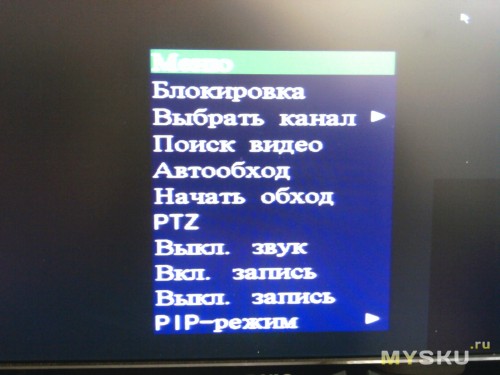
3.2 Панель Быстрого меню
Переместите курсор на знак стрелки, чтобы активировать Быстрое меню, и на экране появятся пять следующих функций:

 Нажмите, чтобы появилась панель переключения каналов, и выберете нужный вам канал.
 Нажмите, чтобы на мониторе появилась панель управления воспроизведения, записанных видеофайлов, и нажмите
  , чтобы воспроизвести последний записанный видеоклип, или нажмите
  , чтобы войти в список поиска.
 Вначале выберете нужный вам канал видео, и нажмите
  , чтобы войти в режим увеличения картинки. В этом режиме нажмите и перетаскивайте красную рамку в то место изображения, которое вы хотите видеть. Чтобы выйти из этого режима нажмите
  .
.
 Нажмите, чтобы выбрать нужный вам аудио канал:
В режиме живого звука, вы сможете выбрать аудио канал живого звука.
В режиме воспроизведения, вы сможете выбрать аудио канал с записанным звуком.
 Нажмите, чтобы войти в режим управления PTZ камерой.
3.2.1 Панель переключения каналов
Нажмите кнопку  на панели Быстрого меню, чтобы отобразить панель переключения каналов.
Важно: Доступные кнопки зависят от модели DVR


Нажмите, чтобы выбрать видеоканал в полноэкранном режиме

Последовательное переключение каналов
Нажмите, чтобы выводить каждый канал в полноэкранном режиме. Показ начинается с 1 канала. Когда последний канал будет выделен, показ снова начнется с 1-ого канала.

Монитор на 4 канала
Нажмите, чтобы войти в режим 4-х канального монитора

Монитор на 9 каналов
Нажмите, чтобы войти в режим 9-ти канального монитора

Монитор на 16 каналов
Нажмите, чтобы войти в режим 16-ти канального монитора
3.2.2 Панель управления PTZ камерами
Нажмите  на панели быстрого меню, чтобы отобразить следующую панель:


Нажмите, чтобы войти в главное меню камеры.
Для подробного изучения меню камеры, ознакомьтесь с её собственным описанием.

Нажмите, чтобы подтвердить ваш выбор

Нажмите, чтобы передвинуть ваш выбор Вверх/Вниз/Лево/Право, или изменить настройки.

Нажмите, чтобы максимально увеличить изображение и вернуться к оригинальному размеру изображения

Нажмите, чтобы увеличить или удалить изображение

Нажмите, чтобы регулировать фокус изображения

Нажмите, чтобы перейти в авто режим

Нажмите, чтобы войти в предустановки PTZ камеры
Источник
H264 digital video recorder
О dvr h.264 вместо вступления
Настройка видеорегистратора dvr h.264 не совсем точное название статьи. В этой статье речь пойдет не о какой то конкретной модели видеорегистратора, а о прошивке. Прошивка эта используется в большинстве бюджетных регистраторов.
Под регистраторами Dvr h.264 в этой статье буду подразумевать все устройства записи камер, использующие общую или похожую прошивку, и которая встречается в абсолютном большинстве видеорегистраторов. Не так уж много брендов имеют собственную прошивку. Как правило это более дорогие бренды, например -Hikvision с дочкой HiWatch. Те что подешевле — ROKA, FalconEYE, Zaun, SpaceTehnology и др. имеют идентичный интерфейс, похожую прошивку, и одни и те-же болячки. Возможно даже что большинство делается на одном заводе. По этому если у вас бюджетный видеорегистратор, эта статья для вас.
Смена пароля
Сменить пароль по умолчанию это не обязательно первое, что нужно сделать при настройке. Но чтобы подчеркнуть важность этого пункта, я коснулся его уже в самом начале статьи. Слишком часто пароль оставляют дефолтным, просто чтобы клиент не забыл. На самом деле на эти регистраторы сбросить пароль на много проще, чем на тот же Hikvision, а последствия от взлома мамкиными хакерами могут быть очень неприятными. От отключения записи, до выкладывания в сеть приватных роликов.
Выбор режима
Практически все видеорегистраторы сейчас являются гибридными. DVR или XVR, в отличии от NVR, позволяют подключать не только камеры по коаксиалу ( 960H, AHD, TVI, CVI ), но и IP камеры. По моему мнению, если ip камер не много, они небольшого разрешения, и нет необходимости в сложных функциях, то выгоднее использовать dvr. Сменить режим можно в окне «Настройка инструменты режим канала»

dvr h.264 выбор режима
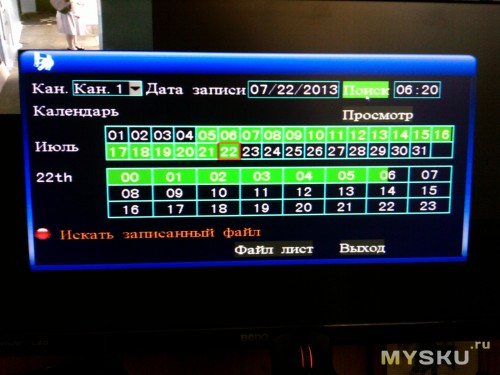
Дата и время
Настройка даты и времени производится в окне «Настройка общие». Тут обычно достаточно выбрать часовой пояс и скорректировать время. Тут-же необходимо убедиться что выбрана перезапись диска, так как в старых версиях по умолчанию не была включена перезапись.
 dvr h.264 настройка даты
Но это еще не все с датой и временем. Последнее время я стал замечать что в регистраторах с этой прошивкой время постепенно отстает. За пол года время может отстать примерно на час, что не критично но неприятно. От этой беды есть решение, но оно работает только если видеорегистратора будет подключен к интернету. Но об этом дальше.
Служба NTP
Что-бы решить проблему с отставанием времени необходимо включить и настроить службу NTP в «Настройка Сетевые службы».
Находим в интернете ip адрес любого рабочего ntp сервера, например 194.149.67.130 ( ntp.psn.ru ), и ставим галочку «Включить».

Теперь устройство само будет синхронизировать время в интернете согласно установленному ранее часовому поясу.
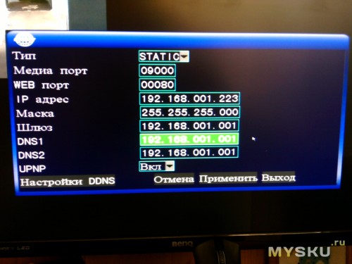
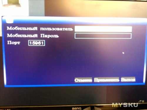
Сетевые настройки
Без этого не заработает не NTP служба, не мобильный доступ. Тут есть только один момент — по умолчанию на этих прошивках выставлен статический адрес 192.168.1.10 . Рекомендую поставить галочку «Вкл. DHCP». Тем самым мы включим автоматическое получение сетевых настроек от маршрутизатора, что поможет исключить ошибки сети. Ну и если канал интернета маленький, можно выставить приоритет на скорость.

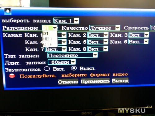
Настройка записи
Этот очень важный пункт в настройках, по сути настраивать и не надо. Во всех версиях этой прошивки выставлена автоматическая запись на все каналы что оптимально в большинстве случаев. Качество записи в «Настройки Компрессия» тоже выставлено оптимально. Дам только пару советов:
- Если нужно увеличить время записи, можно сократить число кадров в секунду до 18, а то и до 12. На 18 кадрах нетренированный глаз не видит разницы. На 12 заметны небольшие задержки, в прочем практически не влияющие на комфортность просмотра.
- Запись только по тревоге позволяет значительно увеличить время записи. Но нужно учитывать что некоторые действия, например проезжающий в дали автомобиль или сработка сигнализации автомобиля, могут быть не зафиксированы в записи. Детектор движения срабатывает не сразу, по этому часть события перед сработкой будет не записана. Не рекомендую использовать запись только по тревоге, если время хранения архива не является критичным.
Включение детектора движения
Вести запись только по движению я не рекомендую, но считаю что нужно обязательно включать детектор движения. Если детектор движения у камеры включен, то в записях движение будет выделяться красным цветом. Это значительно помогает в поиске событий и хорошо экономит время.

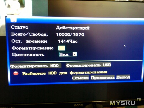
Оповещение о проблемах с диском
Проблема с диском это наиболее частая проблема в видеорегистраторах. Жесткий диск в системе видеонаблюдения изнашивается очень быстро по тому что запись ведется постоянно. Именно по этому рекомендуется использовать жесткие диски специальных серий, например WesternDigital серии purple или Seagate SkyHawk. Но у этих бюджетных видеорегистраторов есть еще одна проблема — блоки питания. Очень часто блоки питания со временем «проседают», и уже не дают достаточно мощности для работы жесткого диска. И тогда камеры показывают, а запись не ведется. Что бы нерабочий жесткий диск не оказался неприятной неожиданностью , необходимо в настройках «Тревога Лог ошибок» включить зуммер и или сообщение на пунктах «Диск отсутствует» и «Ошибка диска». В «ошибка диска» не лишним будет включить «Автоматическая перезагрузка», так как часто диск может выдать ошибку, но заработать после перезагрузки.

Так же можно включить зуммер при потере сигнала, что может быть полезным если «умрет » блок питания камер или окислятся разъемы. Однако, при переходе камер на ночной режим, блок питания может кратковременно «проседать», что может вызвать ложные срабатывания.
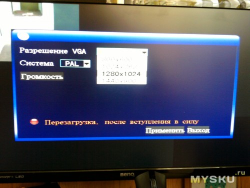
Разрешение экрана
Далеко не всегда к системе видеонаблюдения на постоянную подключен монитор или телевизор. Часто он требуется только в случае происшествия, когда надо просмотреть и сохранить на флешку записи. Если к видеорегистратору не будет постоянно подключен монитор, нет смысла менять разрешение экрана при настройке, ведь в дальнейшем если потребуется подключить монитор, не поддерживающий большее разрешение, вы не сможете сменить разрешение пока не подключите к более подходящему монитору. Однако, если монитор используется, то обязательно выставьте максимально поддерживаемое монитором разрешение — нагрузка на глаза будет меньше.

Коррекция изображения с камер
На последок можно поиграться с настройками камер — в основном это подкрутить яркость. Старайтесь не переборщить с насыщенностью, ведь неточность передачи цвета может показать неправильные приметы подозреваемого 🙂
Заключение.
Прошу прощения за второпях написанную статью, к сожалению на большее у меня пока не хватает ни времени, не терпения. Настройка видеорегистратора может не ограничиваться теми пунктами что указанны в статье, но в большинстве случаев больше ничего настраивать не надо. Надеюсь что мой труд будет оценен не со стороны красоты слова и орфографии, а со стороны полезности. Оставлю здесь ссылку на инструкцию к видеорегистратору на русском языке.
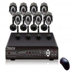
Устройство видеозаписи, записывает видео на HDD SATA с 8 аналоговых камер, используя формат сжатия H.264 с разрешением до Full D1 (720х576) пикс. и максимальной скоростью до 100 к/с. Видеорегистратор может, комплектуется и 2 USB-портами. Для удаленного доступа к устройству предусматривается ПО NEMON, предоставляемое в комплекте. STR-0885 имеет 8 канала аудио, тревожные входы/выходы и может выполнять оповещение о тревоге по электронной почте.
Формат сжатия Н.264 и экономия дискового пространства
Использование в STR-0885 алгоритма компрессии Н.264 обеспечивает высокое качество видеоизображения при существенной экономии дискового пространства. Применение Н.264 также особо актуально для передачи видео по сетям с ограниченной пропускной способностью. Помимо встроенного HDD 8-канальный видеорегистратор может дооснащаться еще 2 жесткими дисками, обеспечивая дополнительное увеличение объема архива. При необходимости возможно копирование видео на DVD/CD через встроенный DVD-RW или на внешние USB-накопители.
Управление PTZ-функциями поворотных камер
Данный видеорегистратор оснащен интерфейсом RS-485, поддерживает протоколы Pelco P и D, а также других производителей и позволяет управлять PTZ-камерами с помощью компьютерной мыши, пульта ДУ, кнопок фронтальной панели и/или подключенной выносной клавиатуры. В видеорегистраторе через интерфейс RS-232 можно подключаться к POS/ATM-терминалам и получать с них текстовую информацию.
Через 4 USB-порта STR-0885 позволяет подключать компьютерную мышь и внешние накопители для копирования данных. Кроме того, видеорегистратор имеет 8 тревожных входов и 1 релейный выход, к которым могут быть подключены датчики и исполнительные устройства. По сигналу тревоги он способен сгенерировать тревожное сообщение и выполнить оповещение по E-mail или вывести видео на Spot-монитор.
сверхнизким 8-канальный DVR
Поддержка VGA выход
Характеристики
Спецификация
Спецификация Показывать
Видео/аудио вход
Сжатие видео H.264
Видео вход 8 каналов
Интерфейс видео входа BNC (1,0 В, 75Ω)
Звуковой вход 1 канала
Интерфейс аудио входа RCA
Видео/аудио выход
Визирование по экрану NTSC:D1 (704 x 480)/PAL:D1 (704 x 576)
Выход VGA 1280×1024
Разрешение записи СИФ
Видео выход (канал) 1
Аудиовыход (канал) 1
Синхронное воспроизведение (канал) 4
Драйвер жесткого диска
Тип интерфейса SATA
Единичная мощность (Hard Disk Not Including)
Максимальная емкость (Т) unlimited
Внешний интерфейс
Сетевой интерфейс RJ45 10M/100M/1000M Адаптивный Ethernet-интерфейс
Интерфейс USB 2.0 2
Последовательный интерфейс RS485
DVR — Дополнительные возможности
Система обеспечения Microsoft Windows 2000, Android, iPhone OS, Symbian, Microsoft Windows XP, Windows7, Mobile Pocket, Мобильный
Язык Китайский упрощенный, Итальянский, Китайский традиционный, Португальский, Английский. Русский
Пульт дистанционного управления Да
Управление мышью Да
Режим записи Запись по тревоге, Запись при обнаружении движения, Запись по расписанию, Ручной режим записи
Сохранение видео Интернет, Жесткий диск
Резервная копия Диск USB, Жесткий диск
Общие характеристики
DVR — Источник питания 12
DVR — Потребляемая мощность (Вт) 4
DVR — Рабочая температура (° С) 0-50
DVR — Влажность (%) RH 10-90%
DVR — Размеры (длина х ширина х высота, мм) 260*45*234
Датчик изображения
Тип датчика CMOS
Размер датчика 1/4 дюйма
Сигнальная система NTSC, PAL
Объектив (мм) 6
Угол обзора (степень) 90
Минимальное освещение (люкс) 0
Физические свойства
Параметры питания
Входное напряжение (V) 100-240
Выход постоянного тока (V) 12
Полная нагрузка средней выходной мощности (А) 3
Параметры кабелей
Длина 10m/20m/30m
Коннектор BNC, DC
Содержимое упаковки
Содержимое упаковки CD, Пульт дистанционного управления, 2 12V 5A Источник питания, DVR, Мышь
Сам регистратор: 
Просмотр и сохранение записи видео

Возможность просмотра через мобильные устройства
Управление простой мышью через USB

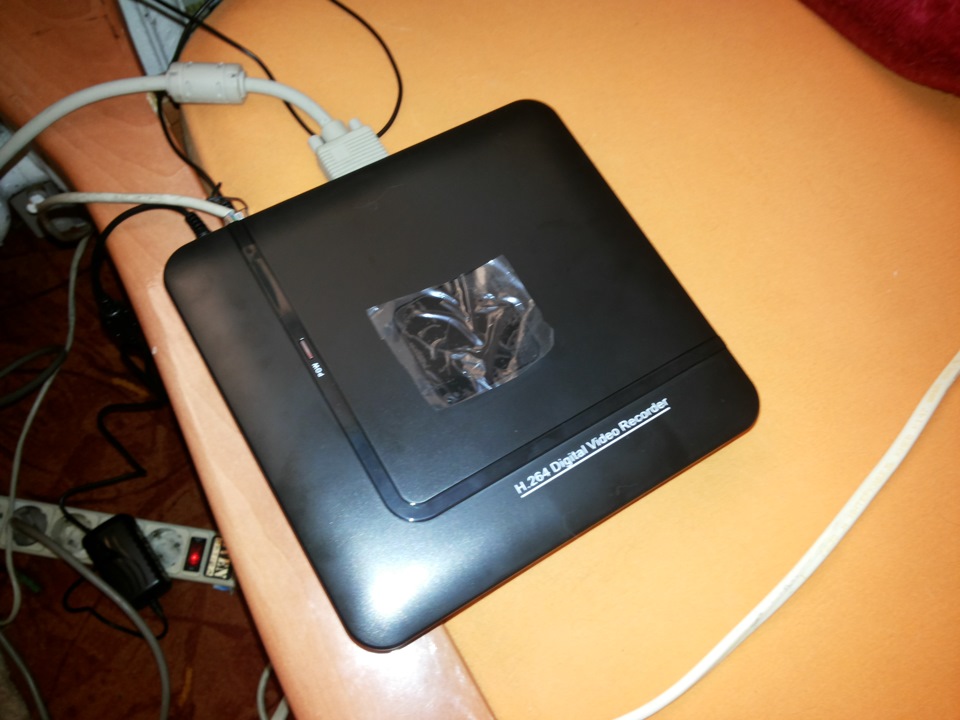
Видеорегистратор N1004F DVR H264 для IP камемер. Т.е. 4х канальный. Бывает такой же на 8 камер но цена там на почти 5 долларов больше… Т.к. камер в месте его установки будет и есть (смонтированы давно) 2 штуки то этого регистратора с головой хватате…
Теперь по посылке:
Заказан за 35.18 доллара, посылку отгрузили через день… И уже через 18 дней он приехал… Трек номер предоставлялся. Отправка была обычной почтой из Китая. УПАКОВКА ОТЛИЧНАЯ! коробка заводская! в ней МЯГКАЯ ХРЕНЬ))) типа ПУПЫРКИ только ТЮНЕНАЯ)))))
По устройству:
Размеры? соответствуют описанию на сайте производителя!
Пайка нормальная! Не ногами)))))
Качество достойное, внутрь можно поставить даже 3.5 жесткий диск… но за неимением такого был поставлен 2.5 на 1 Терабайт… Приблизительный обьем записи у камер о которой я вам расказывал вчера в формате h265 = 480 мегабайт 20 минут… Т.е. этого жесткого диска хватит в полне дня на 4 без напряга… Места внутри навалом! ЕСТЬ ИНДИКАТОР работы КРАСНАЯ ПИМПОЧКА
По работе устройства
Работает эта штука на мног обыстрее чем встроенное меню камер… Не знаю что за зверюшка там внутри… но приятно)) ощущать разницу… Греться да! греется градусов на 40-45 не больше! может меньше. радиатор руки не обжигает если кто боится что сгорит или перегреется то можно допилить доп кулер или поменять на процессоре радиатор… там все элементарно и просто даже 2 дырки для креплений вентелятора есть в плате! Работает стабильно при том что на улице доходит до +33 в тени (на солнце 48)… в помещении бывает почти так же как в тени…
По подключению
DVR подключить очень просто :
0) выкручиваем 4 болта/шурупа крестик, открываем коробку и вставляем жесткий диск. болтики из комплекта не подходят к диску 2.5 WD Sata2 Blue 2T… прейдется искать дугие))) прикручиваем его снизу в посадочные места и собираем коробочку…
1) берем DVR подклчюаем его к +12 вольтовому блоку питания из комплекта.
2) втыкиваем мышку в USB MOUSE
3) втыкиваем VGA кабелем монитор…
4) Подаем питание… и ждем около 30 секунд он загрузится а в это время на экране будет красоваться белый экран с надписью H265 или что то в этом духе))))) там в видео ниже есть все…
5) При первом включении DVR наровит стереть на_иг все что у вас есть на HDD так что будьте внимательны прежде чем ТЫКАТЬ то что спрашивает вас ДА ДА ДА ?))))) ЧИТАЙТЕ БУКВЫ! ЧТОБ ПОТОМ НЕ ПЛАКАТЬ !
Включили))) Довольны))) Эмоции преполняют после покупки и того какой вы молодец)))) что у вас он запустился… Прекрасно…
По настройке IP для DVR и как его найти в ЛОКАЛКЕ.
Просто быстро удобно вот к этому приучают нас Китайцы))))) Изначально устройство установило себе само IP 192.168.1.9 потому что был включен DHCP ))) Логин admin пароль пусто… поэтому искать его надо в РОУТЕРЕ по новым IP или в настройках СЕТИ посмотреть можно че там у него стоит сразу))))
p.s. — Про IP камеры подключаемые к нему можно почитать в нашем общем Алиэкспресовском блоге… ТУТ Я делал обзор по уличной камере. Скоро добавлю по внутренней… Хотя производитель заявляет что поддерживаются все что только можно)))) любые устройства… Но я этого лично проверит не могу!
Поиск IP камер в сетке…
Если камеры висят в локалке то найти их через DVR очень просто и есть как минимум 2 варианта:
1) поиск по всем устр-вам в локалке
2) принудительно вбить IP камеры в нашем случае это были 192.168.1.10 и 192.168.1.11…
Добавление IP камер в DVR
Правой кнопкой мыши открыть меню на названии канала CAM1 или CAM2 , 3 , 4 в то в какое хотите добавить камеру… в поле добавить камеру вам нужно указать :
1) IP добавляемой камеры
2) Поток который вы хотите ее ловить Основной ил Экстра… или МУЛЬТИ!
3) Логин и пароль камеры
4) Если выбрать мульти канал будет серфить с одной камеры на другую в одном окне! Вроде прикольно) но мне кажется функция бесполезна…
По записи видео в DVR с ваших IP камер…
тут есть как минимум 3 вариантов
1) по движению
2) по таймеру
3) постоянно
4) по закрытию камеры
5) по звуку (если в камерах есть МИКРОФОН)
Короче полный фарш для мога))) Можно настраивать и настраивать… У меня включено постоянно… всегда и со звуком… Места хватает… да и надо обкатать 🙂
Функционал?
Более расширеный чем у камеры
Доступ в него из интернета?
Возможен через много сайт xmeye производителя там в видео он есть на коробке… Нужно зарегистрироваться и свое устройство по ID и можно будет заходить удаленно и смотреть онлайн! Регистрация бесплатна. На андроид есть приложение тоже называется xmeye, имея логин и пароль к вашему аккаунту вы сможете засерфить в свою камеру из вне))))) если конечно в DVR будет открыт порт 3546 для доуступа из мобильного устройства)) и облака!
п.с. — многие думают что ОБЛАКО это ДРОПБОКС, ЯНДЕКС, МЕГА, МЕЙЛ РУ ДИСК и тд итп НО это вы так думаете))))) Китайцы думают об этом иначе! ДЛЯ НИХ ОБЛАКО ЭТО ПРОСТО ДОСТУП К ВАШЕМУ УСТРОЙСТВУ ИЗ ВНЕ))))поэтому снимаем РОЗОВЫЕ очки и спускаемся на землю))))
А дальше?Дальше много инетресных дней или ночей))) у вас предстоит для просмотра 100500 записей вашим регистратором Вы разберетесь сами))) или пишите в личку я подскажу что то))) вам
Источник

H.264 Network Digital Video Recorder User’s Manual
-1-
H.264 Network Digital Video Recorder User’s Manual
Notice:
Please don’t remove the top cover for avoiding shock hazard. If maintenance is required,
please contact qualified service staff for preventing the parts from being damaged.
Caution:
Please don’t put the equipment in places with rainwater or high humidity for preventing
fire or shock hazard.
Notice:
In order to ensure constant compatibility, please connect the computer or peripheral
equipment through prot connecting wire. The user is possible of being deprived of the
right to operate the equipment in relation to any alternations or modifications not
authorized by the organizations in charge of compatibility.
-2-
H.264 Network Digital Video Recorder User’s Manual
Precautions before installation and utilization
If the product is required to be installed and maintained, please contact qualified service staff or system engineering operator.
Please do not operate the product beyond the temperature, humidity or power supply range provided in the specification.
Service temperature range of the equipment is 0oC ~ +50oC, and the relative humidity is lower than 85%.
Input power supply of the equipment is DC 12V/5A.
For the efficiency and service life of the hard disk are subject to temperature effects (especially high temperature), the optimal
service temperature range of the equipment is +20oC ~ +30oC.
Please operate the hard disk carefully.
If the hard disk is moved when in operation, it is possible of being damaged. Do not move the hard disk right after energization
or deenergization (about 30s).
Please protect the hard disk against electrostatic damage.
Please don’t stack or erect the hard disk.
Please don’t fix the hard disk by electric screwdriver.
Please wipe the equipment by dry cloth.
Please don’t block the vent of the equipment.
Please don’t place the equipment near heat source, such as electric heater, burner or other heat producing appliances.
Please prevent the power line, especially the plug, convenient socket and any contacts between power line and the equipment.
Please prevent the hardware from dropping into the slot opening of the equipment, or else the equipment is possible of
permanent damage. Please cut off the power supply immediately and contact qualified service staff for treatment as soon as
possible.
Please operate the equipment carefully. Please don’t knock and shake the equipment.
Please don’t place the equipment in water or moisture, and do not operate the equipment in humid area. If the equipment is
damped, please take treatment at once. Please cut off the power supply immediately and contact qualified service staff for
treatment as soon as possible. The moisture is possible of damaging the equipment and causing electrostatic shock.
Please use mild chemicals to lightly wipe the equipment rather than cleaning it by chemicals with great corrosivity.
Please don’t overload the extension wire or power outlet of the equipment, or else fire or electric shock is possible of presence.
Please record and keep your settings, which will be of service to your treatment when the system setups are required to be
altered or unforeseen troubles take place.
Please don’t apply copy, disassembly, reverse compilation, reverse engineering and illegal deliver to export control areas to the
equipment.
Notice: This is a comprehensive instruction. Please check the practical
functional configuration when in use!
-3-
H.264 Network Digital Video Recorder User’s Manual
CONTENTS
1
.
P
r
o
d
u
c
t6
overview························································································· 6
·
·
·
·
·
·
·
·
·
·
·
·
1
.
1
P
r
o
d
u
c
t7
properties························································································· 7
·
·
·
·
·
·7
9
2 .
P a n e l
a n d
r e m o t e
controller········· ···· ······ ···· ···· ····· ···· ·· ······ ···· ···· ····· ···· ·· ······ ···· ···· ····· ···· 11
2
.
1
F
r
o
n
t 11
panel ·························································································· 12
·
·
·
·
·
·
·
·
·
2
.
2
R
e
m
o
t
e 13
controller····················································································· 13
·
·
·
·
·
·
·
· 14
2
.
3
R
e
a
r 15
panel·························································································· 15
·
·
·
·
·
·
·
·
·
·
·
·
21
3
. 21
Installation······················································································· 22
· · · · · · · · · · · · · · · · · · · · · ·
3
.
1
G
e
n
e
r
a
l 26
installation···················································································· 26
·
·
·
·
·
·
·
· 27
3
.
2
S
e
l
e
c
t
i
v
e 28
installation···················································································· 28
·
·
·
·
·
·
30
4 .
M a j o r
f r a m e
a n d
b a s i c 30
operation· · · · · · · · · · · · · · · · · · · · · · · · · · · · · · · · · · · · · · · · · · · · · · · · · · · · · · · · · · · · · · · · · · · · · · · · · · · · 31
4
.
1
S
t
a
r
t
u
p
a
n
d 32
shut-down··················································································· 33
4 . 2
U s e r
l o g o n
a n d 34
management· · · · · · · · · · · · · · · · · · · · · · · · · · · · · · · · · · · · · · · · · · · · · · · · · · · · · · · · · · · · · · · · · · · · · · · · · · · 35
4
.
3 36
Preview······················································································· 40
·
·
·
·
·
·
·
·
40
4
.
4
V
i
s
u
a
l
recording····················································································· 41
·
·
·
·
·
·
·
·
·
· 43
44
5
.
M
a
i
n
menu······························································································
-4·
·
·
·
·
·
·
5
.
1
M
e
n
u
H.264 Network Digital Video Recorder User’s Manual
8
.
4
O
u
t
p
u
t 44
regulation· · · · · · · · · · · · · · · · · · · · · · · · · · · · · · · · · · · · · · · · · · · · · · · · · · · · · · · · · · · · · · · · · · · · · · · · · 44
8.5 Reset to default········································································· 45
9 .
R e m o t e
n e t w o r k
c o n t r o l
a n d 45
m a n a g e me n t · · · · · · · · · · · · · · · · · · · · · · · · · · · · · · · · · · · · · · · · · · · · · · · · · · · · · · · · · · · · · · 49
9
.
1
R
e
m
o
t
e 51
access························································································· 54
·
·
·
·
· 55
9
.
2
R
e
m
o
t
e 56
connection····················································································
·
·
·
·
· 58
9
.
3 60
Control························································································ 63
·
·
·
·
·
·
·
·
·
·
·
9
.
4
Setup··························································································
·
·
·
·
·
·
·
·
·
9 . 5
I n s t r u c t i o n
t o
toolbar························································································
9
.
6
O
t
h
e
r
operations·····················································································
·
·
·
·
·
·
·
·
·
A p p e n d i x
1
–
G e n e r a l
t r o u b l e
shooting· · · · · · · · · · · · · · · · · · · · · · · · · · · · · · · · · · · · · · · · · · · · · · · · · · · · · · · · · · · · · · · · · · · · · · ·
Appendix 2 – Product specifications and technical
p a r a m e t e r s · · · · · · · · · · · · · · · · · · · · · · · · · · · · · · · · · ·
A p p e n d i x
3
–
H D
s p a c e
estimate· · · · · · · · · · · · · · · · · · · · · · · · · · · · · · · · · · · · · · · · · · · · · · · · · · · · · · · · · · · · · · · · · · · · · · · · · · · · · · ·
-5-
H.264 Network Digital Video Recorder User’s Manual
1. Product overview
The H.264 digital video record for monitoring purpose is applicable to household, medium,
small scale office areas,bank,road surveillance,supermarket and other circumstances, and
integrates hard disk record player, video multiplexer and network server. In order to reach the
top mutual connectivity and operationality, this series of digital record player for monitoring
purpose adopts the leading monitoring framework in this industry which is constructed from the
front end to the rear end. With the latest scientific and technological system framework,
powerful compression/decompression engine and intelligent visual recording algorithm, the
system is liable to realize multiple functions for meeting the increasing requirements of the
monitoring industry on function, efficiency, reliability, in-commission rate and so on.
* This Manual just as 8 channel standalone DVR for example to explain,all pictures using
all of 8CH standalone DVR in Standard,4channel/16channel just for reference.
*Below instruction means:
: 4CH
4channel Standalone DVR;
8CH
8channel Standalone DVR;
16CH 16channel Standalone DVR.
1.1 Product properties
4/8/16 sets of colored or monochrome camera can be connected and signal in PAL/NTSC
format is applicable.
H.264 Baseline Profile image compression standard and adjustable visual recording quality
ADPCM sound compression/decompression
Overall operation of six functions – visual recording, playback, real-time video monitoring,
backup, control and remote monitoring can be operated simultaneously.
Fastest visual recording speed:Fastest speed for each channel of CIF: 30 (NTSC) / 25 (PAL)
pieces per second,
Fastest playback speed:Fastest speed for each channel of CIF: 30 (NTSC) / 25 (PAL) pieces per
second, and can be used for 4-channel playback
Real-time display, each set of camera is 30 (NTSC) / 25 (PAL) pieces per second
Be applicable to event visual recording, schedule visual recording and manual visual recording.
Be capable of playing back and searching according to time or event (alarm, movement and
sensory alarm).
Shielding alarm function, for preventing the lens from being deliberately shielded by someone
Several formats of display frames: full screen and 4 /8/9/16 divisional frame formats
Alarm polling and routine polling functions
Intelligent movement detection with adjustable detection area and sensitivity
Powerful sensing alarm visual recording function, of which the toggle condition and visual
recording channel linkage can be set
4CH :1 SATA hard disk can be used at most, maximal value of each hard disk is up to 1TB
8CH :4 SATA hard disks can be used at most, maximal value of each hard disk is up to 1TB
16CH :4 SATA hard disks can be used at most, maximal value of each hard disk is up to 1TB.
USB2.0 interface, through which the visual recording file can be backed up into U disk and
mobile hard disk
Built-in DVD writer, which is applicable to writing and backup function of compact disc
(optional)
Ethernet interface is provided for realizing remote monitoring, remote playback, acoustic
monitoring, remote setting and remote software upgrading through network browser.
Provide PTZ control
Be applicable to user’s authority limitation, system lock and other safety guard functions.
-6-
H.264 Network Digital Video Recorder User’s Manual
2. Panel and remote controller
2.1 Front panel (For there is variance in model and function, please refer to
practical product.)
1. LED:
1:
:POW:
:indication power supply 2: HDD:
:hard disk visual recording
3: NET:
:network data transmission indication
5:
USB:
USB backup data indication
7:
WORK: DVR runing
4: PLAY:
:play back indication
6: ALARM: alarm indication
2. IR: infrared receiving window of the remote controller
NOTICE:Other keys’ function same to remote controller, please check the instruction at
next chapter in ‘Remote controller’.
2.2 Remote controller
The remote controller can be used for replacing all button operations on the front panel. Under
the condition of obstruction free, the effective distance of the remote controller is 10m or so.
Name
[POWER]
Operating instruction
When the system at standby
mode ,press this key will be
entered in Start-up;
when the system operation
Name
[ ]
SWITC
H
-7-
Operating instruction
Switching of 1/4/8/9/16 Preview
window mode
H.264 Network Digital Video Recorder User’s Manual
[DEV]
[ ]REC
[ ]SEAR
CH
indication,press this key up to
3seconds will be,entered in
shut-down menu
Device selection
Visual recording control
Visual recording playback
[FN]
[
]
Slow playback, 1/2×, 1/4×, 1/8×
and single frame play
[
]
Fast playback, 2×, 4× and 8×
playback
[-]
Stop
[+]
Start playing under searching state,
Play/pause
[ ]MU
TE
[FOCUS
]
[ZOOM]
[ ]
[
]
[ ]
Switching of full
screen/multi-window playback
modes
[ ]MEN
U
Access main menu
[
Close soft keyboard
Close current window
Exit from current control
Return to last menu
]ESC
[PTZ]
Access/exit from cradle head
control under preview state
[▲▼◄►
]
Control item for four-direction
selecting window
▲▼ Select the menu items of the
relevant menu
◄► Expand/retract the menu at
the next level of the relevant menu
Control the rotation direction of the
cradle head under PTZ mode
Relevant menu of the current preview
channel is ejected under preview state.
Relevant menu of the current playback
channel is ejected when in professional
playback.
Soft keyboard is called under edit
mode.
Switching of Lens
IRIS/FOCUS/ZOOM modes
Lens control, volume reduction and last
item of the list (OK selection)
Lens control, volume increase and last
item of the list (OK selection)
Mute permission/prohibition
Switching of Lens FOCUS modes
Switching of Lens ZOOM modes
[0~9]
Digital input
Corresponding channel is magnified in
full screen under preview state.
[10+]
Fast key for 10 to 16 channel is
magnified in full screen under preview
state(press this key at first,then press
the 0~6 number)
[ ←]
Return key,delete the charecters
[SEQ]
Skipping, and polling control when
starting polling setting
[BACK
UP]
Backup of visual recording
[OK]
Operation confirmation
Switching of full screen/multi-frame
under preview state
Select/cancel the current item in list box
Select/cancel check state in check box
Switch to edit regional(time,date,ip
address etc)
2.2.1 Start use the remote controller
Under the default factory indication,Remote controller can control the device in directly,but
when the device number is changed,must press the DEV key at first,then input the number for
which you want to control device(The default number for each Standalone DVR is 0,can be
changed in “System setup” of “System setup”),then the Remote controller can be controlled the
currently device at this time.
Notice:when the device number set to 0,this device will accept all of the control signal from the
same device.
-8-
H.264 Network Digital Video Recorder User’s Manual
2.3 Rear panel (For there is variance in model and function, please refer to
practical product.)
Rear Interfaces of 8-channel Equipment
1. VIDEO INPUT(CH1-CH8): this set of BNC contacts is used for connecting the camera.
2. AUDIO INPUT(CH1-CH8): this set of RCA contacts is used for coupling into acoustic
pickup and other audio input devices.
3. VIDEO OUTPUT: for connecting the monitor output with monitoring purpose.
4. AUDIO OUTPUT: this set of RCA contacts send acoustic signals to outer sets such as trumpet.
The playback of sound recording shall be put out by this set of contacts.
5. VGA(MAIN OUT VGA, Optional): for connecting the VGA display to D-SUB 15-pin jack
contact.
6. LAN(Ethernet contact): for connecting to 10/100Base-T Ethernet
7. RS-485: for connecting to PTZ camera
8. SENSOR(ALARM IN)
4CH:Support 4channel alarm input;
8CH:Support 8channel alarm input;
16CH: Support 16channel alarm input.
alarm input without limitations on input type (can either be the normally open type or the
normally closed type);
Ground terminal of the alarm detector is connected in parallel with the ground terminal of the
hard disk video recorder;
NC terminal of the alarm detector is connected to the DVR alarm input terminal (one of
SENSOR1~8);
When the alarm device is supplied by external power supply, it shall be grounded with the hard
disk video recorder.
Alarm input circuit:
-9-
H.264 Network Digital Video Recorder User’s Manual
Alarm input connection:
9. ALARM(ALAR
ALARM(ALARM
(ALARM OUT)
OUT)
4CH:Support
1 channel alarm output;;
4CH
8CH:Support
2 channel alarm output;
8CH
16CH:
16CH Support 2 channel alarm output;
Alarm output for switching value, normally open contact, power supply is required by the
external alarm device;
Alarm output circuit:
- 10 -
H.264 Network Digital Video Recorder User’s Manual
10. USB1(BACKUP): be able to be connected with U-DISK and mobile hard disk, which are used
as backup device for backing operation,and for upgrade in future.
11. USB2(MOUSE):be able to be connected with USB Mouse(Only for connect the USB
Mouse,no other USB device.)
12. DC 12V (POWER IN): DC 12V
3. Installation
Following installation procedure shall be executed by qualified service staff or system
engineering operator.
3.1 General installation
Please refer to the connection scheme of the following figure for connecting each setting.
Corresponding equipment shall be selected as per the practical situation.
Camera: cameras are connected through coaxial cable.
- 11 -
H.264 Network Digital Video Recorder User’s Manual
Main display: main display is connected with monitoring television by BNC contact, or it is
connected with VGA display through optional VGA contact. The main display is used for
displaying each real-time video or play back videos.
Hard disk: the equipment is able to be equipped with four SATA hard disks at most and shall
be connected with each power line and drop-out line. The installation steps of the hard disk are
as follow:
The local power shall be cut off and the top cover shall be opened by screwdriver.
1. Secure the hard disk (3.5”) by screwdriver.
2. Connect power line and drop-out line.
3. Secure the top cover of the equipment.
Precautions: 1. All the hard disks can only be used for visual recording after being. Please
refer to hard disk formatting/clearance contents in hard disk management
section.
2. Please cut off the local power when installing or removing the hard disk.
Power supply: please insert the DC12V power plug into power socket
3.2 Selective installation
Voice input: please contact the voice input contact (AUDIO INPUT) to camera or other voice
outputs of the sound source. The voice input shall be set to corresponding camera.
Voice output: please connect the voice output contact (AUDIO OUTPUT) to trumpet.
Alarm input: please connect the alarm input to outer set, such as sensor or magnetic reed
switch.
Alarm output: please connect the alarm output #1 to normal close (NC), normal open (NO) or
alarm signal. At most two output alarm devices are allowed to be coupled in according to the
actual demand.
Ethernet: please connect the Ethernet contact to 10/100Base-T Ethernet. Refer to the contents
provided in network setting section for relevant settings.
USB 2.0 backup interface: be able to be connected with U-DISK and mobile hard disk, which
are used as backup device for backing operation.
Infrared (I/R) remote controller: the digital record player can be controlled by remote
controller.
PTZ camera: please connect RS-485 contact to PTZ camera through special cable. The
system is applicable to various kinds of PTZ camera including Pelco D, Pelco P protocol Dome,
and other high-speed dome control protocols. Only cameras applicable to the same protocol can
be connected with the same contact. Please refer to cradle head setup section for setting proper
communication parameters, and then the control operation shall be carried out by selecting
“cradle head control” under the shortcut menu of the right button.
- 12 -
H.264 Network Digital Video Recorder User’s Manual
4. Major frame and basic operation
4.1 Start-up and shut-down
4.1.1 Start-up
◆ If the indicator light of [POWER] is off, please operate as the following steps:
Step one: please plug in if the power supply is not plugged, and then the equipment shall be
started; in case the equipment is not started, please go in the next step;
Step two: open the power switch of the equipment, and then the equipment shall be started.
◆ If the indicator light of [POWER] is in red, the equipment can be started only by lightly
pressing [POWER] key.
After start-up, the video output is defaulted as multi-frame output mode. If the starting duration
is within the setting time of the timed visual recording, the visual recording function shall be
automatically started by the system.
If the system is not equipped with hard disk prior to start-up, following prompt shall be shown
after logging in: (refer to fig. 4-1)
Fig. 4-1
4.1.2 Safe shut-down mode:
Enter [main menu] → select “system shut-down” in [log out].
(Fig. 4-2)
Fig. 4-2
(Refer to Fig. 4-3)
Fig. 4-3
4.1.3 Abnormal shut-down (shall be prevented as far as possible):
- 13 -
H.264 Network Digital Video Recorder User’s Manual
A. Switch off the power switch
The power supply shall be prevented from being directly cut off through switching off the
power switch on rear panel as far as possible when the equipment is under operation (especially
when in visual recording).
B. Directly pull out the power line
The power line shall be prevented from being pulled out as far as possible when the equipment
is under operation (especially when in visual recording).
Prompt: under certain environment, the abnormal power supply is possible of resulting in
deviant operation of the hard disk video recorder, and the hard disk video recorder is
likely to be damaged when the condition is serious. Regulated power supply is
recommended under such condition.
4.2 User logon and management
4.2.1 Logon
How to enter the menu mode?
Press key “MENU” to enter the main menu interface of the equipment.
Click right button of the mouse and select “main menu” to enter the main menu interface of the
equipment.
Press shortcut key “SEARCH” to enter operating interface of playback.
Press shortcut key “visual recording/REC” to enter operating interface of manual visual
recording.
Press shortcut key “cradle head/PTZ” to enter the operating interface of cradle head control.
Three system users, namely “admin”, “user” and “default”, are defaulted by the system and
cannot be deleted. Initial password for user “admin”, the user with highest authorization for
carrying out all operations, is 666666. Initial password for “user”, who is capable of carrying
out visual recording, playback, backup, parameter setting and other operations, is 123456;
however, no new users are permitted to be added or no system upgrading is allowed. The
“default” is defaulted as the user with lowest authorization who only has the right of
surveillance. (Refer to Fig. 4-4)
- 14 -
H.264 Network Digital Video Recorder User’s Manual
Fig. 4-4
Measures for password safety: the code is permitted to be input for only 5 times within every
30min, or the account will be locked out.
Notice: Please timely alter the defaulted password for security purpose. Refer to section “user
management” for adding or modifying user.
About input: except the front panel and remote controller of the hard disk video recorder can be
used for input operation, the soft keyboard, which will be ejected by clicking the left button
within the input box, can be utilized.
Prompt: if the system power supply is cut off or the system is forced to be shut down when
the video recorder is under visual recording, timed visual recording and alarm visual
recording operating states, the visual recording prior to power-off will be automatically
kept by the video recorder and the operating state before power-off will be automatically
recovered.
4.3 Preview
It shall directly enter the preview frame after normal logon.
Preview frame overlaps the current date and time and displays the name and state of each
channel. Meanings for the icons of the channel state are as follow:
1
3
This icon is shown on the
channel frame when the
channel is in visual recording.
This icon is shown on the
frame when the channel is
under dynamic detection.
2
4
This icon is shown on the
channel frame when video lost
is happened to the channel.
This icon is shown on the
channel frame when the video
is shielded.
4.4 Visual recording
Visual recording mode can be selected by the user as per his/her demand. The visual recording
symbol will be displayed on the channel frame when visual recording in various modes is
happened to the channel.
- 15 -
H.264 Network Digital Video Recorder User’s Manual
4.4.1 Channel visual recording
Prompt: the user is required to have operating authorization when carrying visual
recording operation. Please make sure the hard disk is installed and properly formatted
before operation.
1) Enter the operating interface of visual recording
Click the right button of the mouse under preview state and select “visual recording control” in
the menu ejected, or enter the operating interface of visual recording through “main menu” →
“visual recording control”. In addition, it can be directly enter the operating interface of the
visual recording control by pressing key “visual recording/REC” under preview state: (Fig.
4-5)
Fig. 4-5 (notice: 4 channel and 16 channel equipments have little different)
2) Instruction for operating interface of visual recording
[Auto visual recording] set the channel visual recording, and carry out visual recording based
on the conditions of timing, dynamic detection and alarm set in visual recording setup;
[Manual visual recording] with the highest priority, common visual recording shall be carried
out for corresponding channel after manually press the key without respect to the current state
of each channel;
[Stop recording] all channels stop recording;
[All] All channels can be selected;
4.4.2 Visual recording playback
The system is equipped with two visual recording display modes, namely fast playback and
advanced playback. When in playback, the file can be selectively played or played according to
the time sequence.
1) Fast playback
The fast playback can be realized by pressing key “SEARCH” under preview frame, or clicking
the right button of the mouse and select “visual recording playback” in the menu ejected. The
fast playback is able to play a single channel.
2) Advanced playback
The advanced playback can be realized by selecting “main menu” → “visual recording
playback”. It is applicable to not only the independent playback of 4-channel visual recording,
but also the simultaneous and comparative playback of the four channels according to the time
- 16 -
H.264 Network Digital Video Recorder User’s Manual
sequence.
3) Visual recording search (Fig. 4-6)
Fig. 4-6 (notice: 4 channel and 16 channel equipments have little different)
[Searching date] date of the visual recording required to be searched.
[Starting time]/ [Terminal time] Duration required for searching, and the starting time has to be
smaller than the terminal time.
[Searching type] Appoint the type of the visual recording to be searched, and all, common
visual recording, external alarm visual recording and dynamic detection visual recording can be
selected.
[Searching channel] 8 channels, of which single channel or several channels can be selected.
[File play] select the required file in search list and click the key “play”, or directly double
click the target file.
[4-channel synchronous play] do not select any files in the list box, set the searching date,
starting time, terminal time and channels required to be played synchronously, and then click
key “play” for playing.
Prompt: when synchronous play is required under the condition that some files are
selected, the operation can be done by clicking “search” to search the file again and then
eliminating the selection.
4) Play control bar (Fig. 4-7 and Fig. Fig. 4-8)
Fig. 4-7 Fast playback
- 17 -
H.264 Network Digital Video Recorder User’s Manual
Fig. 4-8 Advanced playback
Key
Description
Play/pause
Return to normal
play condition
from fast and slow
play
Volume control
Key
Four-frame mode
Description
Stop
Key
Description
Slow play
Fast play
Sound/mute
Open file
Full screen /
multi-window play
Single-frame mode
Exit from playback
Description:
1. Playing speed, channel, time, progress and other information of the current file are displayed
on the panel of the playback control bar.
2. Playback control is valid for all channels under the mode of contrastive playback according to
precise time. It is valid for the current selected channel when the playback is selected as per the
file.
3. The system will jump over the time quantum, during which no visual recording is carried out
by any channels, under the synchronous playback mode based on time.
4. Positioning can be carried out by using the mouse to shift the progress bar.
Prompt: the volume can be controlled through keys + and - on remote controller.
4.4.3 Backup of visual recording file
“Main menu” → “file backup”. (Fig. 4-9)
Visual recording backup of the hard disk video recorder can be realized by DVD writer, USB
memory device, internet download and other methods.
The backup operation on hard disk video recorder is introduced herein. Refer to relevant
contents in “Section VIII, Remote Network Control and Management” for backup via network
download.
- 18 -
H.264 Network Digital Video Recorder User’s Manual
Fig. 4-9
[Detect] Click the key “detect”, if the system is connected with backup device, type, partition,
capacity and other information of the device will be displayed in the list box. The newly
inserted device is required to be re-detected.
[Remove] the loaded backup device will be safely removed by clicking key “remove”.
[Cease] cease the current backup task. The backup task in writing mode cannot be ceased at
midcourse.
[Add] Search the file required to be backed up.
[Delete] Delete single or several files selected in backup file list box. This operation resets only
the backup file list without eliminating the files.
[Empty] Empty all files in the list box. This operation resets only the backup file list without
eliminating the files.
[Backup] Back up all files in the list box into the appointed backup device. When in backup,
please select a backup device with sufficient capacity.
The visual recording in hard disk video recorder can be searched based on time, channel,
searching type and other information, and the searching information will be displayed in the list
box. Multiple files can be added at the same time, and the files to be backed up will be
displayed in the file list of “file backup” dialog box after adding operation.
- 19 -
H.264 Network Digital Video Recorder User’s Manual
Fig. 4-10 File backup
Fig. 4-11 Backup search (notice: 4 channel and 16 channel equipments have little different)
During backup, the fulfillment of the current backup will be displayed in real time at the lower
right corner.
Visual recording files backed can be checked by the user. Common format for the name of the
visual recording file is: channel number + second, minute, hour, day, month, year.lvf.
Prompt: during the backup operation, the fulfillment of the current backup will be
displayed in real time at the lower right corner of the backup window. Other operations
can be carried out during the backup, and prompt will be automatically ejected after
completion.
- 20 -
H.264 Network Digital Video Recorder User’s Manual
5. Main menu
5.1 Menu guidance
Main menu
Single-stage
submenu
Visual
recording
playback
System
information
Hard disk
information
Log
information
Edition
information
On-line user
General setup
Coding setup
Visual
recording
setup
System setup
Cradle head
setup
Network
setting
Alarm setting
Video check
Local display
Visual
recording
control
Hard disk
management
Option remarks
Realize the visual recording search and playing back
functions, and the list search can be done as per the type,
channel and time of visual recording, and the results are
displayed in list. Choose the file for playing back.
N-common visual recording, A-alarm visual recording and
M-dynamic check
Display the state of hard disks, including the type of hard disk,
slot location, total capacity and available capacity.
Display the log of important events in the system and search
according to the type and classification of logs.
Display the characteristics of system hardware, software
version and date of issue.
View the information of –n-line user, including IP and log-in
account and so on.
Basic parameters as system time, date format, video system,
language setting and local number.
Setting of encode mode, frame rate and quality parameter of
audio and video frequency.
Including the time setting of prerecording, timing visual
recording, dynamic detection and external alarm.
Setting of visual recording plan per week, and four stages a
day.
Setting of cradle head protocol and communicating parameter.
Setting of parameters of network address, port, PPPoE and
DDNS.
Setting of types of sensor, alarm visual recording channel,
alarm output and relevant parameters.
Setting of sensitivity and zone of dynamic detection, and
treatment mode of video lost, video shielding alarm (alarm
output and visual recording channel).
Selection of menu color and transparence, and setting of frame
polling mode and polling interval
Auto-visual recording, manual-visual recording or stop visual
recording
Display of state of hard disks and hard disk formatting.
- 21 -
H.264 Network Digital Video Recorder User’s Manual
Organize or withdraw a defense for alarm and allow or
prohibit the alarm output.
Alarm
control
User account
Advanced
options
Exception
handling
System
maintenance
Output
regulation
Reset to
default
Add or delete the user and change the authority of a user or the
code.
The buzzer will give alarm or start the alarm output for any
abnormities of system.
Setting of items need to be maintained in the system and
updating the system software.
VGA output parameter and audio output regulation
Recover all or partial parameters selected to the factory
settings, and reset to default, user account, system and
language are not included.
File backup of the designated visual recording files to the
backup facility.
File backup
Log-out
Log-out the active user and input the code again at the next
operation.
Close and restart the HD visual recorder.
5.2 Menu operation
“Main menu” (Fig. 5-1)
Fig. 5-1
Main menu includes nine function options, as visual recording playback, system information,
system setup, and visual recording control, and hard disk management, alarm control, advanced
- 22 -
H.264 Network Digital Video Recorder User’s Manual
options, file backup and log-out.
Description:
All the settings of the following submenus will be effective after being saved.
If the check box is filled, it means the function is chosen, and those unfilled as not chosen.
5.2.1 System information
“Main menu” → “System information” (Fig. 5-2)
System information includes: hard disk information, log information, edition information and
on-line user.
Fig. 5-2
(1) Hard disk information
“Main menu” → “System information” → “Hard disk information”. (Fig. 5-3)
Display the state of all connected hard disks of the system, the type of hard disk, slot location,
total capacity and available capacity.
- 23 -
H.264 Network Digital Video Recorder User’s Manual
Fig. 5-3
(2) Log information
“Main menu” → “System information” → “Log information” (Fig. 5-4)
Display the system log for the convenience of view and login of users.
[Log type] [All], [System operation], [Setting], [Data management], [Alarm event], [visual
recording operation] and [user management] are optional.
[Starting time] Set the starting time of log search.
[Terminal time] Set terminal time of log search.
Push “Search” button after the setting of log time quantum and type, and the system will display
the required log in the list, and push “<<” and “<<” for page turning leftward and rightward.
Fig. 5-4
(3) Edition information
“Main menu” → “System information” → “Edition information” (Fig. 5-5)
Display the edition of system software, MCU edition, hardware edition and date of issue and so
on.
- 24 -
H.264 Network Digital Video Recorder User’s Manual
Fig. 5-5
(4) On-line user
“Main menu” → “System information” → “On-line user” (Fig. 5-6)
View the information of network users logged in the local HD visual recorder, including
account name and IP.
Fig. 5-6
5.2.2 Hard disk management
“Main menu” → “Hard disk management” (Fig. 5-7)
Display the attribute of hard disk; type, HD total capacity and available capacity.
Push administration button to operate and the formatting hard disks are currently supported.
- 25 -
H.264 Network Digital Video Recorder User’s Manual
Fig. 5-7 (notice: 4 channel and 16 channel equipments have little different)
Prompt: Please stop all visual recordings of the system before HD formatting.
6
System control
6.1 Cradle head control
6.1.1 Connection
1) Connect the control line of ball machine to RS-485 interface of DVR. Pay attention to
485+(A) and 485-(B) matching order.
2) Connect the video line of the ball machine to video input of DVR.
3) Electrify the ball machine.
6.1.2 Preparation
1) Set the control address of ball machine and choose relevant control protocol.
2) Switch the current frame to the corresponding display channel.
6.1.3 Operation
Click the right mouse button to enter the shortcut menu under real-time monitoring frame, and
choose “cradle head control” or push “PTZ” key to enter the control frame: (Fig. 6-1 and Fig.
6-2).
Fig. 6-1
[Cradle head] Move the mouse to the upper, lower, left and right locations of the current frame,
and the screen will show the arrow in corresponding direction, and this time, press and hold the
mouse, the control of corresponding location can be entered, and the control can be done
- 26 -
H.264 Network Digital Video Recorder User’s Manual
through the panel or ←↑→↓ buttons of the remote controller.
Notice: Refer to some of full function High speed dome,this device also support to control
for:Top left corner、
、Top right corner、
、Lower left quarter and Lower right quarter.
[Speed] Regulate the rotating step length of the cradle head through a slide bar, mainly for the
controlling of direction operation. The longer the step length is, the faster the rotational speed
is.
[-Diaphragm +] Regulate the diaphragm.
[-Focusing +] Bring into focus finely.
[-Zooming +] Lens zooms in and out. Magnification can be changed by using the mouse wheel
under the current frame.
Prompt: Use FN key to switch the modes of diaphragm, focusing and Zooming. Use + and keys to control.
Fig. 6-2
[Operation] <Boundary-scan> moves and control the ball machine to a point, for setting of left
boundary, and then move to the other point horizontally, for setting of right boundary.
<Automatic scan> can control the automatic scanning of the ball machine at left and right
boundary after starting.
<Cruising setting> can record all moving tracks of the cradle head after starting, and then stop
for storage.
<Cruise control> can control the rotation of ball machine automatically, as per recorded tracks
of “cruise setting” after starting.
The system will regulate the diaphragm automatically after the starting of <Automatic
diaphragm>, to reach the optimum efficiency.
<Back light compensation> will supply the light source compensation under the dark ambient
light.
★Notice: Operating functions need to be supported by headend equipment and matched with
the protocol.
[Assistance] Input the auxiliary output number that needs control, and click the buttons “Open”
or “Close".
[Presetting point] Adjust the direction and angle of the camera, and input corresponding
presetting point numbers and then click “Setting” button, thus, the presetting point number of
the menu is set.
- 27 -
H.264 Network Digital Video Recorder User’s Manual
Input the presetting point number, and click “Transfer” button, the camera will be switched to
the corresponding location of presetting point automatically.
6.2 Video control
Click the right mouse button under the real-time monitoring frame to enter the shortcut menu
and choose “video regulation”. (Fig. 6-3)
Fig. 6-3
Regulate the brightness, chromaticity, contrast and saturation of the current frame and use
mouse wheel or ←→ keys for fine regulation.
6.3 Acoustic monitoring
The site sound can be monitored under the real-time monitoring frame. Click the right mouse
button on the monitoring channel frame, to enter the shortcut menu, and then choose “Start
monitoring”. If the acoustic monitoring of the channel is started, the choice menu shows “Close
monitoring”.
6.4 Alarm control
6.4.1 Alarm control
“Main menu” → “Alarm control”. (Fig. 6-4)
[Automatic defense] The defense shall be set and withdrawn as per the plan of alarm setting.
[Manual defense] The priority is the highest. Push down Manual defense, the corresponding
channels will be under the defense state.
[Alarm withdraw] Withdrawing the defense state, the alarm input may not be reacted.
[Output enable] Whether the corresponding alarm output is enabled when alarming.
[All] means all channels can be selected;
Set the alarm output port. The white are the selected ones; push the Confirm button for storage
and then exit, and push Cancel button for storage and exit.
- 28 -
H.264 Network Digital Video Recorder User’s Manual
Fig. 6-4 (notice: 4 channel and 16 channel equipments have little different)
6.4.2 All clear
Click the right mouse button under the real-time monitoring frame, to enter the shortcut menu,
and choose “All clear”, to enter the following frame (Fig. 6-5).
Fig. 6-5
Click “Clear” button to stop the current alarm visual recording and alarm output, but not
withdraw the defense, so that the alarm can be triggered again.
Icon description:
Grey means all alarm input channels are in defense withdraw state.
Green means one or more alarm channels are in defense setting state.
Red means one or more alarm inputs are triggered. Click the icon to enter the” All clear”
window, and view the specific alarm information.
- 29 -
H.264 Network Digital Video Recorder User’s Manual
7. System setup
“Main menu” → “System setup” (Fig. 7-1)
System setup includes: “General setup”, “Coding setup”, “Visual recording setup”, “Cradle
head setup”, “Network setting”, “Alarm setting”, “Video check” and “Local display”.
Prompt: System setup only can be entered by the users with authority.
Fig. 7-1
7.1 General setup
“Main menu” → “System setup” → “General setup”. (Fig. 7-2)
Fig. 7-2
[System time] is for modifying the current system date and time of the visual recorder; after the
modification, click the “Time setting” button at right for storage.
[Date format] is for choosing date displaying format, including three formats as
- 30 -
H.264 Network Digital Video Recorder User’s Manual
year-month-date, month-date-year and date-month-year.
[Date separation character] has three selections: “-”, “/”, “.”; if “.” is selected, the system time
will be displayed as: 2008.07.20.
[Time format] includes 24-hour system and 12-hour system.
[Language selection] displays the dynamic selection of language.
[Identification number] is used under the situation of one remote controller controlling of
multiple HD visual recorder. It is only for the condition that the address on the remote
controller is the same with the HD visual recorder number.
[Video system] offers two systems as PAL and NTSC. The system will be effective by
restarting after the modification of video system.
Prompt: All current visual recordings shall be stopped for time setting.
7.2 Coding setup
“Main menu” → “System setup” → “Coding setup”. (Fig. 7-3)
Fig. 7-3 (notice: 4 channel and 16 channel equipments have little different)
[Channel] Choose the channels that need to be configured. “All” means all channels need to be
configured.
[Coding type] “Video” is only for video image, and “Video-Audio” is for video and audio
recording synchronously.
[Coding size] CIF.
[Code flow control] includes fixed code rate and dynamic code rate.
[Coding quality] divides into 6-grade quality: best–better–good–middle–bad–worse.
[Code rate] Select code rate. The higher the code rate is, the better the visual recording is and
the larger the HD memory space is needed.
[Frame rate] 1 ~25 frame/s (PAL) or 1~30 frame/s (NTSC) adjustable continuously.
- 31 -
H.264 Network Digital Video Recorder User’s Manual
[Time superposition] and [Characters superposition] Time and channel title superposition is
available for each channel. If selected, it means the time and channel are superposed to the
video. Click the Setting button to set the time and channel titles to the superposition location on
the video, and drag the time or channel title to the proper location. When visual recording files
are played back, the time and channel information of visual recording will be displayed on the
frame.
[Copy the current settings to the following channels] Users can copy the settings of the channel
to the other channels, realizing the same coding setup.
Prompt: If the code flow control is set as the dynamic code flow, [Code rate] setting value
means the upper limit of code rate.
7.3 Visual recording setup
“Main menu” → “System setup” → “Visual recording setup”. (Fig. 7-4)
The default visual recording plan of HD visual recorder is 24-hour continuous visual recording.
The timing visual recording setup can be done as required, namely, the visual recording shall be
as per specified type in the timing period.
Fig. 7-4 (notice: 4 channel and 16 channel equipments have little different)
Including time quantum setting of common visual recording, dynamic visual recording and
alarm visual recording.
[HD full] When the visual recording hard disk is full, how can the system operate? “Automatic
overlaying” means that the system will overlay the earliest visual recording files to continue
visual recording, “Stop visual recording” means the system will stop the current visual
recording.
[Visual recording time] means the time interval of forming the visual recording files, and the
- 32 -
H.264 Network Digital Video Recorder User’s Manual
setting range is 5-120 minutes.
[Channel]/ [Visual recording plan] pull down menu. Choose relevant channel number/week for
setting, and “All” means the setting of all channels.
[Alarm presetting] Visual recording for 5 seconds before alarming.
[Time quantum] means the visual recording modes of the channel within the time quantum, and
there are four time quanta can be set. The time for the same visual recording mode in different
time quantum can be repeated, and the time setting range is from 00:00-24:00. Push Save
button after parameters of all channels have been set up.
[Common visual recording], [Dynamic visual recording] and [Alarm visual recording] for
setting of visual recording modes in the time quantum, single or multiple choices are available.
[Copy the current settings to the following channels] Users can copy the settings of the channel
to the other channels, realizing the same visual recording setup.
Prompt: Users must save the settings of all channels.
7.4 Cradle head setup
“Main menu” → “System setup” → “Cradle head setup”. (Fig. 7-5)
Fig. 7-5 (notice: 4 channel and 16 channel equipments have little different)
[Channel] Choose the channel connected with the camera of the ball machine and “All” means
the setting of all channels.
[Decoder address] is set to the corresponding address of ball machine, with range of 0-255.
★Notice: This address must be the same with that of the ball machine, or otherwise, the
ball machine cannot be controlled.
[Protocol type] Choose corresponding control protocols: Pelco_P, Pelco_D, and the default is
Pelco_D.
- 33 -
H.264 Network Digital Video Recorder User’s Manual
[Baud rate] Choose relevant baud rate for the ball machine, and the cradle head and camera of
the relevant channel can be controlled, with the range of 1200-115200, and the default of 9600.
[Data bit] The range is from 5 to 8, and the default is 8.
[Stop bit] 1 and 2; and the default is 1.
[Check] None, Parity Odd, Even Parity and Default As None.
[Flow control] None, Xon/Xoff, HD and Default As None.
[Copy the current settings to the following channels] Users can copy the settings of the channel
to the other channels, realizing the same cradle head setup.
★Notice: The parameter settings of cradle head of each channel shall be saved separately.
7.5 Network setting
“Main menu” → “System setup” →“Network setting”. (Fig. 7-6)
Fig. 7-6
[Network card IP] Press number key or soft keyboard to modify the parameter values of IP (IP
shall be set here only).
[Subnet mask] Setting of IP network mask address.
Physical Address
Setting of Physical Address of the network card, and the digital input
should adopt the hexadecimal system. (Fig. 7-7)
Fig. 7-7
[Default gateway] Setting of gateway IP.
[DNS server] Setting of DNS server IP.
- 34 -
H.264 Network Digital Video Recorder User’s Manual
[Server port] Defaulted as 7777. Setting of port as per actual demand of users, and restarting for
validation.
[HTTP port] Generally defaulted as 80. It can be effective after modification and restarting. If
the port number is modified, the http port must be displayed for access (as
http://192.168.0.117:1234).
[Enabling DDNS] through dynamic domain name resolution server. Supporting of 3322 free
dynamic domain name resolution of CN (registered account: http://www.3322.org).
[Auto-enabling of PPPoE] Input the account name and code of PPPoE offered by ISP (Internet
ISP internet), and then click “Dial-up” to start connection, and after that, “PPPoE IP” will
display the acquired dynamic IP of WAN automatically. Choose “Auto-enabling of PPPoE”, the
HD visual recorder will start for trying to connect PPPoE.
Prompt: If the PPPoE is successfully dialed up, the users’ remote access of HD visual recorder
is available as per the IP shown on [PPPoE IP]. Access is available through network card IP in
LAN.
7.6 Alarm setting
“Main menu” → “System setup” → “Alarm setting”. (Fig. 7-8)
Fig. 7-8 (notice: 4 channel and 16 channel equipments have little different)
[Alarm input] Choose relevant alarm channel number, and “All” means the settings of all
channels.
[Equipment type] Choose the normally open/normally closed of alarm input (voltage output
mode).
[Alarm delay] Set relevant delay time (5~255s). The system will delay for relevant time
automatically, after the external alarm is canceled, and then close the alarm and linkage output.
[Channel polling] Single frame polling will be display for the channels of visual recordings, if the
- 35 -
H.264 Network Digital Video Recorder User’s Manual
alarm signal is sent out, and the polling time should be set in [system setup] and [output mode].
[Visual recording channel] Choose required visual recording channels (secondary selection is
optional). The system will start the alarm visual recording automatically, when alarming, if the
system is under “Auto-visual recording” mode (visual recording mode refers to “3.4.1 channel
visual recording”), and the “Alarm visual recording” in the “visual recording setup” is within the
effective time (refer to “6.3 visual recording setup” for details).
[Alarm output] Linkage alarm output when an alarm is given.
[Time quantum] Set the time quantum of alarm output as per week, indicating the allowable alarm
output or screen prompt within the relevant time quantum.
[Alarm output] In the selected time quantum, the relevant alarm output devices can be interlocked
when alarming.
[Screen prompt] In the selected time quantum, the screen will remind relevant information when
alarming.
[Copy the current settings to the following channels] Users can copy the settings of the channel to
the other channels, realizing the same alarm setting.
★Notice: Users need to save the settings of each channel separately.
7.7 Video check
“Main menu” → “System setup” → “Video check”. (Fig. 7-9)
Description:
1) There is no zone and sensitivity setting in the video lost and shielding detection when
switching the detection type.
2) Channel frame will display the dynamic detection, video lost and video shielding marks during
the process from channel detection to video change.
3) Drag and drop the mouse directly to select the dynamic detection zone. The detection zone can
be set by pressing the mouse and dragging to the right lower part, and the detection zone can be
cleared by pressing the right mouse button and dragging to the right lower part. Please click the
“Save” button in the video check menu after exiting from the zone setting.
7.7.1 Dynamic detection
It can be seen that the motion detection alarm will be started, if the movable signals with
presetting sensitivity is detected in the system, through video image analysis (Fig. 7-9).
- 36 -
H.264 Network Digital Video Recorder User’s Manual
Fig. 7-9 (notice: 4 channel and 16 channel equipments have little different)
[Channel] Choose the channels required of dynamic detection zones, and “All” means the setting
of all channels.
[Alarm type] Choose the type of detection and setting: motion detection.
[Alarm delay] Set the delay time of alarm (5-255s). After the video lost alarm, the system will
delay for relevant time automatically, and then stop the visual recording and linkage output.
[Visual recording channel] Choose required visual recording channels (secondary selection is
available). The system will start the motion detection visual recording automatically, in case of
video dynamic detection, if the system is under “Auto-visual recording” mode (visual recording
mode refers to “4.4.1 channel visual recording”), and the “Motion detection visual recording” in
the “visual recording setup” is within the effective time (refer to “7.3 visual recording setup” for
details).
[Alarm output] The relevant alarm linkage output will be started during the dynamic detection.
[Time quantum] Set the time quantum of alarm output as per week, indicating the allowable alarm
output or screen prompt within the relevant time quantum.
[Sensitivity] can be set in several levels as: highest, higher, general, low and lower.
[Alarm output] Relevant alarm output devices can be interlocked for dynamic detection alarm in
the selected time quantum.
[Screen prompt] Relevant information can be reminded on the screen for dynamic detection alarm
in the selected time quantum.
[Copy the current settings to the following channels] Click to copy to the other channels after the
setting of visual recording state, and the users can copy the settings of the channel to the other
channels, realizing the same motion detection settings.
[Motion detection zone] Click the Setting to enter in. The setting zone is divided into 192 (16X12)
zones.
- 37 -
H.264 Network Digital Video Recorder User’s Manual
The green zone is the defended area of dynamic detection and the white zone is the non-defended
area. The detection zone can be set by pressing and dragging the left mouse button to the right
lower part and be cleared by pressing and dragging the right mouse button to the right lower part.
Press the Save button after exiting the dynamic detection zone. (Fig. 7-10)
Fig. 7-10
★Notice: Only the parameters of the current detection type can be copied, not including the
detection zone.
7.7.2 Video lost
The system will have relevant treatment as per the settings, if the video image is loss or
interrupted (Fig. 7-11).
Fig. 7-11 (notice: 4 channel and 16 channel equipments have little different)
[Channel] Choose the channels that need to set with video lost detection, and “All” means the
settings of all channels.
[Alarm type] Choose the type of detection: Video lost.
[Channel] It indicates the channels required of visual recording for video lost.
[Alarm delay] Set the delay time of alarm (5-255s). The system will delay for corresponding
- 38 -
H.264 Network Digital Video Recorder User’s Manual
time after the video lost alarm, and then stop the visual recording and linkage output.
[Alarm output] The corresponding alarm linkage output will be started for video lost.
[Time quantum] Set the time quantum of alarm output as per week, indicating the allowable
alarm output or screen prompt within the relevant time quantum.
[Alarm output] Relevant alarm output devices can be interlocked for dynamic detection alarm
in the selected time quantum.
[Screen prompt] Relevant information can be reminded on the screen for dynamic detection
alarm in the selected time quantum.
[Copy the current settings to the following channels] Users can copy the settings of the channel
to the other channels, realizing the same alarm settings of video lost.
7.7.3 Shielding detection
If someone balefully shields the lens, or the video output in single color screen due to rays, the
site image cannot be supervised. But this can be prevented effectively by setting the shielding
alarm (Fig. 7-12).
Fig. 7-12 (notice: 4 channel and 16 channel equipments have little different)
[Channel] Choose the channels that need to set with shielding alarm, and “All” means the
settings of all channels.
[Alarm type] Choose the type of detection: Shielding detection.
[Alarm delay] Set the delay time of alarm (5-255s). The system will delay for corresponding
time after the shielding alarm, and then stop the visual recording and linkage output.
[Alarm output] The corresponding alarm linkage output will be started for video lost.
[Time quantum] Set the time quantum of alarm output as per week, indicating the allowable
alarm output or screen prompt within the relevant time quantum.
[Alarm output] Relevant alarm output devices can be interlocked for dynamic detection alarm
- 39 -
H.264 Network Digital Video Recorder User’s Manual
in the selected time quantum.
[Screen prompt] Relevant information can be reminded on the screen for dynamic detection
alarm in the selected time quantum.
[Copy the current settings to the following channels] Users can copy the settings of the channel
to the other channels, realizing the same alarm setting of video lost.
7.8 Local display
“Main menu” → “System setup” → “Local display”. (Fig. 7-13)
Fig. 7-13 (notice: 4 channel and 16 channel equipments have little different)
[Channel name] Click the channel name to modify the button, and enter the channel name
menu, and the name of all channels can be modified.
[Window color] Windows and menus can be displayed in sky-blue, magenta and light green
optionally.
[Transparence] The background transparence can be set as 25%, 50% and 75%.
[Start-up polling] Start up the polling function of channels, which will be shown under the
preview frame after exiting the menu.
[Polling interval] The polling time can be set with the interval of 5-120s. The polling menu
includes single-frame, 4-frame and 9-frame. The radio boxes in the single-frame line indicate
the polling channels, those in the 4-frame line indicate polling pages (1, 2, 3, 4 channels for
page 1 and 5, 6, 7, 8 channels for page 2), and those in 9-frame line indicate 8-channel menu on
the polling pages. The polling order is from options in single-frame, 4-frame and 9-frame.
8. System management
“Main menu” → “advanced options” displays submenus including: user account number,
exception handling, system maintenance, output regulation, reset to default, and return to the
- 40 -
H.264 Network Digital Video Recorder User’s Manual
above. (Fig. 8-1)
Fig. 8-1
8.1 User account number
“Main menu” → “advanced options” → “user account number”. (Fig. 8-2)
Fig 8-2
The maximum length of the user name’s character is 8 bytes after omitting the beginning and
the end space. The name can be letters, numbers or other symbols.
The maximum number of the users is 12, without repetition of the user name. The admin user
can modify the passwords and rights of all the users, while other users are only able to modify
their own passwords and view their own rights.
Modify password: select the account number which needs modification, input the current user
password, and input the new password of the account number and confirm the password. Press
the “save” button for password modification, and the password can be 0-8 digits. (Fig. 8-3 and
- 41 -
H.264 Network Digital Video Recorder User’s Manual
Fig. 8-4)
★Notice: The current user password refers to the password for the user to log onto the
menu and the admin user is able to modify passwords of the other user with his password.
Fig. 8-3
Fig. 8-4
Add users: to add new users and the user’s controlling rights. Enter into the menu interface for
adding users, input the user name, the password, and the confirmation password in order (the
two passwords must be the same), and then appoint suitable rights for the user in the “right
control” list. “Allow repeated logging in” means that the account number can be used
simultaneously, and that more than one user can enter into the system with the account number
at the same time. (Fig. 8-5)
- 42 -
H.264 Network Digital Video Recorder User’s Manual
Fig. 8-5
There are three default users including the admin, the user, and the default in the system, which
can not be deleted. Among them, the admin is the supreme right user who is entitled to
implement all the operations, while the default user is defaulted to be the low right user in the
factory whose default right is solely the monitoring right. Not only there is no user logging in,
but also the current user has logged out, and then the system will log in with this account
number automatically. The user can complete some operations not requiring logging on by
modifying this account number’s rights.
8.2 Exception handling
“Main menu” → “advanced options” → “exception handling”. (Fig. 8-6)
Fig. 8-6 (notice: 4 channel and 16 channel equipments have little different)
[Exception type] Select the exception type: full hard disk, mistaken hard disk, or broken
network.
[Buzzer alarm] whether allow the buzzer give indications or not if there is any exception.
[Alarm output] Start the alarm linkage output if there is any exception.
- 43 -
H.264 Network Digital Video Recorder User’s Manual
Prompt: Detailed exception information record can be checked through the system log.
8.3 System maintenance
“Main menu” → “advanced options” → “system maintenance”. (Fig. 8-7)
Click “start updating”, and the system will check and update the files automatically.
Fig. 8-7
8.4 Output regulation
“Main menu” → “advanced options” → “output regulation”. (Fig. 8-8)
Control the region, brightness, chromaticity and resolution of the VGA output.
Fig. 8-8
Prompt: When “Reset to default” chooses “local display”, the output regulation can be set
back to the factory settings.
8.5 Reset to default
“Main menu” → “advanced options” → “Reset to default”. (Fig. 8-9)
The system restores the default configuration status in the factory, and corresponding setting
can be resumed based on options on the menu.
Prompt: The menu color, language, the time and date format, the video mode, and the
user account number can not be resumed.
- 44 -
H.264 Network Digital Video Recorder User’s Manual
Fig. 8-9
9 Remote network control and management
9.1 Remote access setting
9.1.1 Network security level setting
Prior to control installation, please program the network security level by the following
operations:
(1) Open the IE browser to choose the “Internet option” in the “Tool” menu.
(2) Choose the “Security” label in the appeared dialogue box. (Fig. 9-1)
Fig. 9-1
(3) Click “Customization level” to enter into the security setting. (Fig. 9-2)
- 45 -
H.264 Network Digital Video Recorder User’s Manual
Fig. 9-2
Set the ActiveX control and pluggable unit
ActiveX control auto-prompting
Run the script of the ActiveX control which is marked to be that can safely implement the
script.
Implement initialization and run the script of the ActiveX control which is not marked to
be that can safely implement the script.
Binary system and the script behavior
Download the unsigned ActiveX control
Download the signed ActiveX control
Perform the ActiveX control and pluggable unit
It’s extremely importation to “enable” the items above.
Prompt: Before control installation, please turn off the fire wall and the anti-virus
software.
9.1.2 Connection setting
The remote access for the hard disk visual recording machine should be carried out through the
network. In the local area network connection, the IP address of the client-side computer must
be in the same network section with that of the hard disk visual recording machine. While in
the wide area network connection, just ensure that two sides can visit the public network, and
carry out connection through the IP address or the dynamic domain name. The following will
mainly focus on the connecting and setting method for the local area network.
Step 1: Click “Network neighborhood” with the right key of the mouse, and click “Attribute”
in the ejected menu to open the “Network connection”.
Step 2: Double click to open “Local connection”. (Fig. 9-3)
- 46 -
H.264 Network Digital Video Recorder User’s Manual
Fig. 9-3
Step 3: click “Attribute”. (Fig. 9-4)
Fig. 9-4
Step 4: Double click “Internet protocol (TCP/IP)”. (Fig. 9-5)
- 47 -
H.264 Network Digital Video Recorder User’s Manual
Fig. 9-5
Step 5: Examine the IP address, subnet mask, and default gateway on the PC. (Parameters in
Fig. 9-5 vary according to specific user’s using conditions)
Step 6: Set corresponding IP address, subnet mask, and default gateway on the hard disk visual
recording machine (refer to 7.5 Network Setting Section). Wherein, the subnet mask, and
default gateway on the hard disk visual recording machine are the same with those of the PC,
and the IP address must be in the same network section but can not be the same with the used
one. Otherwise, it will cause IP address conflicts. Take the figure above as an example, the IP
address should be: 92.168.0.X, wherein, X can not be 40 or 1 (including other IP addresses
currently being used), and can not surpass 255, the subnet mask is 255.255.255.0, and the
gateway is 192.168.0.1.
9.1.3 Control download and installation
After finishing the aforementioned settings, open the IE browser, input http://192.168.0.X
(192.168.0.X is the setting IP address of the hard disk visual recording machine) and confirm.
If the http port of the hard disk visual recording machine setting has been changed, it’s will be a
must to add colon + port number (assume that the current port number is P), like
http://192.168.0.X:P, for correct visit. Then, please choose “Install the ActiveX control”, the
network will download and install the control automatically (Fig. 9-6).
- 48 -
H.264 Network Digital Video Recorder User’s Manual
Fig. 9-6
9.2 Remote connection
9.2.1 Connection
After finishing downloading the control, the logging plate will eject automatically following
operation of the control. (Fig. 9-7)
Fig. 9-7
[Logging mode] Two logging modes are provided.
Log on according to the IP address: Fill the IP address, and the input IP address
should be inconsistent with that of the DVR network setting;
Log on according to the domain name: fill the setting DDNS domain name in
the host computer network settings or the domain name mapped by the router.
“Verify the domain name” can check whether the domain name is effective;
[Port number] The input port number must be in consistent with that of the network setting;
[User name/password] The default user name is admin;
[Preview all the channels automatically when logging on the server] All the channel video
will start automatically after successfully logging on the server (do not start if possible when
connecting through the wide area network);
[Start previewing from Window X] From which window of the control does the preview
image start displaying;
[The dialogue box will exit automatically after successful logging on or logging out from the
server] After successfully logging on the server, the logging window will close automatically;
The host computer corresponding to “Delete” can be deleted;
[Host computer’s alias]: Set the host computer’s alias by oneself, and click “Save”, so that the
user can manage;
Choose “Log” after inputting relevant parameters. (Fig. 9-8)
If the logging operation fails, the prompts as the figures show will eject. Please check the IP
- 49 -
H.264 Network Digital Video Recorder User’s Manual
address, the port number, the user name and the password. (Fig. 9-8)
Fig. 9-8
After logging on successfully, the display will be as below (Fig. 9-9)
Fig. 9-9
9.2.2 Multi-server logging
Synchronously logging on other servers can be realized by clicking the button “Log on” on the
right side of the screen.
9.2.3 Channel incidence menu
Click the right key in the preview window, then the channel incidence menu will eject. (Fig.
9-10)
Fig. 9-10
[Full-screen interface] Enlarge the whole control interface to be full-screen display.
[Full-screen video] Conceal the controlling straps, so as to convert the visual frequency
window to be the full-screen display.
- 50 -
H.264 Network Digital Video Recorder User’s Manual
[Start the acoustical frequency] Open the acoustic monitoring corresponding to the preview
channel.
[Stop preview] Stop the current channel preview.
[Start the visual recording] Maintain the real-time preview in the LCL.
[Fast play] Accelerate the playing speed in the playing status.
[Slow play] Reduce the playing speed in the playing status.
[Screenshot] Intercept the visual pictures in the current window and store in the LCL.
[Search] Search for the visual recording files including local search and remote search.
[Channel name] Set the name of the channel corresponding to the hard disk visual recording
machine, the name of the channel where previewing superposes the visual recording will also
change.
9.3 Control
By clicking the remote control menu “Control” on the right side of the screen, a dialogue box
for server selection will appear. (Fig. 9-11)
Fig. 9-11
Choose the server that needs control to enter into the status control.
9.3.1 General
Restart the server, control and restart the host computer
Stop the server, control and stop the host computer
Remote updating; start the local updating program for upgrading the file which has to be
prepared.
- 51 -
H.264 Network Digital Video Recorder User’s Manual
Fig. 9-12
9.3.2 Video frequency
Remotely adjust the video frequency’s brightness, chromaticity, contrast and saturation degree
so the best visual effect. (Fig. 9-13)
Fig. 9-13
9.3.3 Log
The user can examine logs in the hard disk visual recording machine. (Fig. 9-14)
- 52 -
H.264 Network Digital Video Recorder User’s Manual
Fig. 9-14
[Starting time]/ [Terminal time] Choose the related time quantum.
[Log type] All logs, system logs, configuration logs, data logs, alarm logs, visual recording logs
and user management can be selected.
9.3.5 Downloading
The user can remotely download files on the hard disk visual recording machine, and save them
locally for backup or play. (Fig. 9-16)
Fig. 9-15
- 53 -
H.264 Network Digital Video Recorder User’s Manual
Fig. 9-16
[Channel] Choose the channel requiring search.
[Visual recording type] All the visual records, common visual records, alarm visual records,
and dynamic check visual records.
[Starting time]/ [Terminal time] Choose the related time quantum.
9.4 Setup
Prompt: Choose [Save] to save the current setting, while choose [Save all] to save all the
settings. Click “Setting” on the right side to enter into the setting face plate. (Fig. 9-17)
Fig. 9-17
9.4.1 Local setting
[Common setting] Interface language: Chinese, English.
Adjust the WINDOWS COLOR: RGB color code setting
[Visual recording setup] Catalogue: Choose the local visual recording memory site.
Disk reserving space: visual recording will not use this part of space.
Automatic partitioning period: the setting range is 5-120min.
Automatically covering when the disk is full: be able to check
[Picture setting] Catalogue: Choose the local picture memory site.
- 54 -
H.264 Network Digital Video Recorder User’s Manual
Disk reserving space: Picture saving will not use this part of space.
[Downloading setting] Catalogue: Choose the memory site for the download file.
Disk reserving space: File downloading saving will not use this part of space.
[Stream transmission] Protocol: UDP and TCP for selection. Generally the local area network
chooses UDP, while the wide area network chooses TCP.
Performance: The buffering degree for network data receiving is set based on
the network conditions. The better the real-time property is, the less the
buffering degree is, while the better the fluency is, the bigger the buffering
degree is. Generally speaking, the local area network chooses “the best
real-time property”, while the wide area network chooses either “better
real-time property” or “giving equal attention to the real-time property and the
fluency”.
9.4.2 Common setup, coding setup, visual recording setup, alarm setting, cradle head
setup, movement monitoring, video loss, and shielding alarm
Please refer to the related contents in “Section 6 System setup”.
9.5
Instruction to toolbar
Start Pause Stop
Slow
play
Fast Single Screenshot Visual Playback
recording
play frame
Volume control
Total time for file playing/Current time
9.5.1 Real-time preview control
After successfully entering into the server, the user can preview pictures on the hard disk
visual recording machine in the real-time remotely. Choose a window not being used and click
the “Start” button, the system will eject a choice box for channel connection. The intensified
channel means that it is in the preview state now. By clicking the “Visual recording” button, the
real-time previewed video can be stored in the designated catalogue in the LCL. Clicking the
“Stop” button can stop previewing the window.
- 55 -
H.264 Network Digital Video Recorder User’s Manual
Fig. 9-18
9.5.2 Visual recording playback
The user can either playback the local visual recording files, or remotely playback the files
on the hard disk visual recording machine. Click “Stop” to exit from file playing.
Fig. 9-19
9.6 Other operations
9.6.1 Cradle head and prearranged point control
Fig. 9-20
The arrow buttons direct the cradle head turn towards the above, the below, the left and the
right respectively. Click the middle button to set and call the prearranged point.
- 56 -
H.264 Network Digital Video Recorder User’s Manual
9.6.2 Lens control
Fig. 9-21
[+Focal length-] The lens are drawn further or nearer.
[+Assistant-] Auxiliary switch
[+Image-] Slightly adjust the focal length.
[+Aperture-] Adjust the aperture size.
9.6.3 Window browsing mode
Fig. 9-22
8 window modes are provided for switching: single frame, 4 frames, 6 frames, 8 frames, 9
frames, 16 frames, 25 frames and 36 frames.
- 57 -
H.264 Network Digital Video Recorder User’s Manual
Appendix I general trouble shooting
◎ The host computer fails to start after being connected to the power supply?
·Check whether the power switch on the back of the host computer is opened.
·Check whether the starting operation is correct.
·Check whether the source power is sufficient.
◎ Dose it keep in the starting-up logo frame?
·Physical damages have occurred to the hard disk.
·The system guiding is abnormal.
◎ Starting-up is very slow?
·The hard disk error will lead to repeated hard disk check by the DVR host computer, thus
causing slowly starting-up.
◎ The host computer restarts repeatedly?
·Please check power supply of the host computer. After hitching a lot of hard disks, it’s possible
that the host computer starts up repeatedly due to insufficient power.
·Please disconnect the gridline, and then check if the machine operation is normal. Network with
serious failures is also likely to lead to repeated starting-up of the host computer.
◎ The machine crashed during reproducing or watching the visual recording information by
proper application?
·Check whether there is anything wrong with hitching of the hard disk, and change the failed one
in time.
·Whether the ambient temperature is high.
·Whether there is any heavy-current device near to the host computer or the circumscribing video
device. The heavy current impacts the video cable, and make the host computer fail to work
properly, thus leading to system crash.
◎ Updating operation has failed?
·The host computer is unable to identify the poor U-disk due to its poor compatibility. It’s
recommended to test more than one U, or to use new-brand U-disks.
·The USB port contact is poor. During updating, the voltage fluctuates dramatically.
◎ The image on the invigilator or the TV set is black and white?
·Check whether the video input, DVR host computer, invigilator or the TV set system is
absolutely consistent. If not, please set the invigilator or the TV set system option in the automatic
identification state.
◎ There is no anything displayed on the invigilator or the TV set?
·Check whether the invigilator power supply is opened, and whether the invigilator’s brightness is
in its lowest condition.
- 58 -
H.264 Network Digital Video Recorder User’s Manual
·Check whether the video cable is properly connected, and whether there is anything wrong in the
circuit.
◎ There is obvious water wave in the image, and interference deformation has occurred?
·Whether the video cable is short or broken, or whether there is cold joint or poor connection.
·The video cable bears the power interference. The video cable can extend wire along with the
heavy-current circuits. Meanwhile, please select good-quality shielding lines.
·Within the whole system, only single point earthing rather than multipoint earthing of the central
machine can be applied. Otherwise, there will be common mode interference. Please connect the
DVR host computer to the ground with the grounding screw on its back.
·Check whether aging occurs to the camera, the invigilator or the circuit.
◎Color infidelity occurs to both the real-time image and the visual recording data?
·Whether the output/input video parameters have been adjusted properly in the host computer’s
menu?
·Check that everything is well in the connecting lines.
◎The image distorts, becomes flickering, Distortion, flicker and color cast occur to the image
when using the computer’s display?
Make sure that the VGA connecting line is properly earthed with the host computer.
·High working ambient temperature or poor radiation of the DVR host computer cause abnormal
operation of the VGA display chip or abnormal parameters of related circuit.
◎There will be mosaic during playback of the visual record on the host computer side?
·Low visual recording parameters will lead to overall fall of the visual recording quality, and
mosaic occasionally.
·Damaged section in the hard disks can also cause mosaic during playback of the visual record.
◎The client-side control can not update automatically?
·Whether the IP address visiting the server is correct.
·Whether the browser setting is correct (see Section 8.1.2)
·If the client-side control window has been opened, please close it at first.
·For the reason that the browser ActiveX control supports compatibility, please use the Microsoft
Internet Explorer browser to visit to server.
- 59 -
H.264 Network Digital Video Recorder User’s Manual
Appendix 2 Product specifications and technical parameters
Item
System
Device
parameter
Main
processor
operating
system
System
resource
Operating
interface
input device
Input method
Shortcut
function
Compression
standard
image
compression
Video
compression
Video input
Video output
Video standard
Visual
recording
speed
partitioning
screen
Video
monitoring
8-channel
flush type LINUX
Multi-function operation, support simultaneous multi-channel visual recording,
simultaneous visual record playback, visual recording network operation.
Humanized image menu colloquy interface, support multiple operating methods such
as mouse operation and remote controller operation.
Mouse. remote controller
Digit, English, special character
Shortcut copy and affix operation can be carried out corresponding to the same setting
in the menu; the right-key menu lists the common functions for frame partitioning ,
directly switch the frame by mouse double click.
H.264
ADPCM/PCM
4-channel composite video 8-channel composite video
16-channel composite
(NTSC/PAL)BNC(1.0VP(NTSC/PAL)BNC(1.0VPvideo (NTSC/PAL)
P , 75Ω)
P , 75Ω)
BNC (1.0VP- P , 75Ω)
1channel PAL/NTSC, BNC (1.0VP- P, 75Ω) composite video signal output 1-channel
VGA output(Optional)
Support
simultaneous
Support
simultaneous
output
of CVBS
and
output of CVBS and
VGA(Optional)
VGA
PAL (625 lines, 50 fields/second ), NTSC (525 lines, 60 fields/second )
Real-time mode :PAL 1 frame/second per channel -25 frame/second adjustable NTSC
1 frame/second -30 frame/second per channel adjustable;
1, 4
1, 4, 8, 9
Support alarm channel polling and conventional channel polling
Image
resolution
Real-time monitoring D1 704×576/704×480
visual recording playback CIF 352×288/ 352×240
Frame
information
Video
adjustment
VGA
adjustment
Channel status
display
audio input
audio output
8-channel
High-performance industrial flush-type microcontroller
Monitoring
patrol
Image quality
Audio
4-channel
1, 4, 8, 9, 16
Image quality can be adjusted within 6 levels.
Channel information, time information
Can adjust the output image in each channel, so as to adapt to brightness color
differences of different cameras.
Can set VGA attributes such as output brightness and contrast
Can display channel name, visual recording status, video loss status, dynamic
detection status per channel frame, and display the alarm status in the lower right
corner.
16channel audio input
4-channel audio input
8-channel audio input
200-1000mv 10KΩ
200-1000mv 10KΩ (RCA)
200-1000mv 10KΩ (RCA)
(RCA)
1-channel audio output
1-channel audio output,
- 60 -
H.264 Network Digital Video Recorder User’s Manual
support audio talkback
Hard disk
Hard disk
Space usage
Hard disk
management
Visual
recording
mode
Visual
recording and
playback
Recording
time
Visual
recording
cyclic form
Visual
recording
inquiry
Playback mode
File switching
mode
Multiple
channel
playback
Frame
zooming
Memory
function
Backup
method
Network
function
Network
control
Dynamic
detection
Video
monitoring
and alarming
Video loss
External alarm
Manual alarm
control
Shielding
alarm
4 SATA interfaces can hitch 1-4 hard disks(8018HS
mode can be abet only one SATA HDD)
Audio: PCM 28.8M byte/hour ADPCM 14.4M byte/hour ; video : 56~900M
byte/hour
Non-working disk sleep is good for radiating and reducing power consumption, so as
to lengthen the disk life.
Manual visual recording, dynamic detection visual recording, common visual
recording, alarm visual recording. The priority for supporting visual recording:
manual visual recording> alarm visual recording> dynamic detection> common
visual recording
File record time for visual recording can be set from 1 to 120 minutes (the default
value is 60min.)
1 SATA interfaces
Support the hard disk cycle to cover visual recording
Inquire about visual recording according to the time, type, and channel number.
Multiple slow and rapid play speeds, manual and single-frame play modes, and
support positioning the time by driving the sliding bar.
Support continuous file playing during 4-channel playback
Support simultaneous visual record playback of 4 channels including 1.2.3. and 4
Small frame/4 frames/full screen during multi-channel playback
Support circumscribing USB memory devices (such as common U-disk, moving hard
disk)
support built-in SATA recording CD driver
——
Support online downloading and storing
The monitoring frame in the front channel of the remote access supports simultaneous
connection of 5 users.
Visit and set the system parameters through the client-side software or network
browser
Update the program through the client-side software or network browser to realize
remote maintenance
Watch the operation log through the network
Support online cradle head control
Support remote download storing and visual record playback
Manual visual recording and shooting in the network mode
Speech talkback (supported
by the 16-channel unit)
Multiple frame preview
Region setting: 192 (16×12) detecting regions can be set per frame; the detecting
sensitivity setting: the region can set multi-level sensitivity degree; can link visual
recording or external alarm, or eject screen prompt
can link external alarm output, or eject screen prompt
can link visual recording ,or link external alarm within the setting period, or eject
screen prompt
Can enable or forbid an alarm input channel, organize a defense and withdraw a
defense
can link external alarm output, or eject screen prompt
- 61 -
H.264 Network Digital Video Recorder User’s Manual
Interface
System
message
Alarm input
4-channel alarm input
8-channel alarm input
Alarm output
1-channel relay output
2-channel relay output
Alarm relay
USB interface
30VDC 1A, 125VAC 0.5A (linkage output)
Connect USB devices such as U-disk, moving hard disk and mouse
Network
interface
RJ45 10M/100M
Self-adapting the Ethernet port
RS485
Hard disk
information
Log
information
Version
information
Online user
cradle head control port, support various Protocols
User
management
User
management
Cryptographic
security
protection
Program updating
Logging on, logging out and
turning off the machine
Conventiona
l parameter
Power supply
power
consumption
Application
temperature
Application
humidity
Size(MM)
16-channel alarm input
SATA interface status, capacity and space information of each hard disk.
Display 2000 pieces of the system log up to, and support inquire about the log
information based on the time and type
Display the system version number, MCU version, and hardware issue date.
Display the online users in the network in the real-time
Multi-level user management and multiple management modes. Unified management
over the local and the online users.
Support user and group increase and right modification. Rights of each user can be
customized.
Support password modification.
Users with administrative rights can also set other user’s password.
Account number locking strategy: the password can be tested for five times per 30
min. otherwise, it will be locked.
Update through the WEB and the client-side network
Can be expanded to U-disk updating.
Password logging to ensure the safety.
Humanized menu dialogue when turning off the system menu: provide choices for
logging out the menu user, turning off the machine, and restarting the machine.
Can set the turning off right, so as to ensure that the authorized user turn off the
machine.
12DC, 4A
12DC, 6A
20W~90W
0℃-+55℃
10%-90%
- 62 -
H.264 Network Digital Video Recorder User’s Manual
Appendix III HD space estimate
Hard disk capacity and visual recording can be estimated as per the following table.
Visual
Code
Space
Video
Resoluti
recording
rate
usage/hour
format
on
frame ratio
(kbps)
(MB/h)
(FPS)
768
323M
512
225M
PAL
CIF
25
384
168.7M
256
112.5M
128
56M
768
323M
512
225M
NTSC
CIF
30
384
168.7M
256
112.5M
128
56M
Description: when variant rate is adopted by the coding setup of the system, the code rate is varied
with the motion condition of the image. If the variation of the frame is great, the code rate is
correspondingly in creased. When the set code rate is used, the code rate value is the upper limit of
the coding, which shall not exceed the set point in spite of the alternation of condition.
Hard disk space calculation:
Total space usage = space usage/hour (MB/h) × visual recording time (hour) ×
number of channels
For example, we use NTSC camera to carry out real-time visual recording under CIF resolution,
and the code rate adopted is 512 kbps. The hard disk capacity required by one visual recording of
8-channel DVR is:
Occupied capacity of hard disk =225 (mb/h) × 24 (hours/day) × 30 (days) × 8 (channels)
= 1296000 (MB)
= 1296 (GB)
Therefore, if we need to record the video data for one month (24-hour visual recording for each
day), the hard disk with a capacity of at least 1296 GB is required. Under such condition, the
requirement can be basically met by using two hard disks, of which the capacity is 500G and 750G
separately.
Above method is for reference only. The space usage of the hard disk also can be influenced by
the quality of the real-time camera image.
- 63 -