-
Contents
-
Table of Contents
-
Bookmarks
Quick Links
4033452 / 8
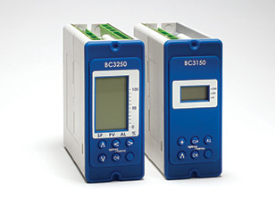
BC3250
Blowdown Controller
Installation and Maintenance Instructions
BC3250
100
50
0
%
SP
PV
AL
OK
IM-P403-89
EMM Issue 8
1.
Safety information
2.
User instructions and
delivery information
3.
System overview
4.
Mechanical installation
5.
Electrical installation
6.
Commissioning
— Quick set-up
— Full
7.
Communications
8.
Maintenance
9.
Fault finding
10. Technical information
— Default settings
11. Appendix
— Summary of the
Modbus protocol
12. Menu map
© Copyright 2017
Printed in GB
Commissioning password
Current legislation states that in order to prevent tampering and potentially
hazardous programming errors, access to the pass codes required to enter
commissioning mode should only be available to qualified and trained personnel.
Enter commissioning
This is done from the run mode by pressing and holding down the
The bar graphs will disappear and the display will show ‘PASS
PASS
CODE’ with ‘8888’ at the bottom right corner of the screen. The
flashing leading digit indicates the position of the cursor. The
CODE
default, or factory set pass code is 7452 but this can be changed
from within the commissioning mode. The pass code can be
entered by using the
the flashing value and the
Pressing
will enter the pass code. If an incorrect pass code is
OK
used, the display automatically returns to the run mode.
8888
This page MUST be removed after
commissioning and kept in a safe,
access controlled location.
button for 5 seconds.
OK
and
buttons to increase or decrease
and
buttons to move the cursor.
IM-P405-89 EMM Issue 8
Summary of Contents for Spirax Sarco BC3250

Контроллер продувки котла BC3250 Spirax Sarco
Контроллер продувки котла BC3250 Spirax Sarco
-
Описание
-
ЗАДАЙТЕ ВОПРОС ПРОДАВЦУ
Описание
Устройство BC3250 – это контроллер продувки для парогенераторов. Открывая и закрывая клапан
продувки, контролирует TDS (общее содержание растворенных в растворе солей) в воде. Кроме того,
контролирует дренажный клапан, который удаляет с днища котла растворенные соли.
Функция оборудования – контроль электрической проводимости жидкости вместе с датчиком
проводимости, дренажным клапаном днища или дренажным клапаном конденсата.
Дренажный клапан днища регулируется таймером.
Контроллер может быть установлен на панели, на DIN-рейке или непосредственно на специальной
монтажной раме, питание 99/264 Vca.
Передняя панель снабжена графическим LCD дисплем и клавиатурой из 5 кнопок.
В случаях, когда датчик установлен непосредственно на котле, можно дополнительно использовать
фильтр с целью увеличения эффекта угасания. Данная система поможет избежать слишком частого
срабатывания клапана в случае турбулентности.

ЗАДАЙТЕ ВОПРОС ПРОДАВЦУ
Table of Contents for Spirax Sarco BC3250:
-
IM-P403-89 EMM Issue 8 30 20 21 22 Bottom blowdown relay Input Open Fig. 22 BCVxx Blowdown Valves with 24 Vac / dc Supply 1 cable / 2pt * Must be common to both connection ends ** Must not be mixed between Vac and Vdc 1 2 3 4 5 6 7 8 9 10 11 Alarm 1 relay Control relay 3 A Fuse L 1 A Fuse N Alarm Norm Input 3 A Fuse BACK FRONT Open Input 3 A Fuse Caution live terminal AC supply Burner supply BCV4x,6x,7x & 8x Optional Limit Switch 2a valve opening 2b valve closing AVF234S 0V ( Common ) * 24 Vac / dc ** Limit Switch Box 4 5 6 7 8 9 S2 ( Xs2 )
-
IM-P403-89 EMM Issue 8 42 6.4.6 INPUT sub menu notes 6.4.6.1 INPUT – TDS – SENSOR – FLT MODE Only shown if the CP32 probe is selected. Allows selection of the action to be taken if the probe detects a fault. ‘OFF’ No action. ‘CLEAN’ If the probe is scaled then the time between probe conditioning cycles will change from the CLEAN-INTERVAL time set to 10 minutes, until the probe is clean. The display will flash
-
IM-P403-89 EMM Issue 8 19 OK BC3250 100 50 0 % SP PV AL Fig. 11 BCS3 system — TDS control with integral take-off and continuous monitoring point from the side of the boiler. OK BC3250 100 50 0 % SP PV AL Fig. 12 BCS4 system — TDS control with intermittent monitoring point from the side or the bottom of the boiler.
-
IM-P403-89 EMM Issue 8 24 Note: Before installing observe the ‘Safety Information’ in Section 1. Warning: Isolate the mains supply before touching any of the wiring terminals as these may be wired to hazardous voltages. Use only the connectors supplied with the product, or spares obtained from Spirax Sarco Ltd. Use of different connectors may co
-
IM-P403-89 EMM Issue 8 52 6.4.13 TEST OUTPUT sub-menu TEST OUTPUT RETRANS TEST OUTPUT VALVE TEST OUTPUT BBVALVE TEST OUTPUT ALARM 1 TEST OUTPUT CANCEL? Enables the output to be adjusted between 4 mA and 20 mA to test the system. Energises / de-energises the TDS valve relay for test purposes. Energises / de-energises the bottom blowdown valve relay for test purposes. Energises / de-energises the alarm relay for test purposes. Resets the system to automatic control. (The sys
-
IM-P403-89 EMM Issue 8 50 TEST DISPLAY TEST INPUT Turns on all the segments on the display. The screen should be completely black if all pixels are working. Press the button to enter test input mode, or the button to exit the test mode and return to the main menu. Displays the signal on each input. TEST OUTPUT Tests the outputs to the required configuration. 6.4.11 TEST sub-menu Allows access to the diagnostic tools.
-
IM-P403-89 EMM Issue 8 57 9.3 Operational error messages Any operational errors that occur will be displayed in the run mode, on the alarms and errors screen. Error message Cause Action 1 Powerout There has been a loss of power to the product during operation. 1. Remove power from product. 2. Check that all wiring is correct. Power fail. 3. Check that the power supply is secure, i.e. does not suffer from ‘brown outs’ 4. Reapply
-
IM-P403-89 EMM Issue 8 35 Rx Tx Master Common Earth* R* R* * See wiring notes Front Slave(s) (Boiler controller) 909192939495969798 H/ DH/ DRx+Rx-Tx+Tx-SCNCOM Fig. 27 RS485 / Modbus half duplex circuit (view from the top) Add link between terminals 91 and 90 EIA / TIA-485 wiring notes continued: — The bus common must be connected directly to protective ground / earth at one point only. Generally this point is at or near the master device. — Consider terminating the two furthest ends of the bus to match the transmission line impedan
-
IM-P403-89 EMM Issue 8 21 4. Mechanical installation Note: Read the ‘Safety information’ in Section 1 before installing the product. The product must be installed in a suitable industrial control panel or fireproof enclosure to provide impact and environmental protection. A minimum of IP54 (EN 60529) or Type 3, 3S, 4, 4X, 6, 6P and 13 (UL50 / NEMA 250 ) is required. If installed in a harsh environment (conductive dust and / or wet conditions), extra protection is required. During installation or
-
IM-P403-89 EMM Issue 8 36 6.1 General information All commissioning for the product is carried out using the front panel. WARNING: On entering the commissioning mode the product will cease normal control. All valves will close, the 4-20 mA and the timer will freeze. For safety reasons, the alarm relay(s) will continue to operate as normal. To regain normal control, return to the run menu by pressing the button. WARNING: If during commission
-
IM-P403-89 EMM Issue 8 28 20 21 22 Bottom blowdown relay Input Open Fig. 20 BCVxx Blowdown Valves with 24 Vac / dc Supply 2cable / 3pt * Must be common to both connection ends ** Must not be mixed between Vac and Vdc 1 2 3 4 5 6 7 8 9 10 11 Alarm 1 relay Control relay 3 A Fuse L 1 A Fuse N Alarm Norm Input 3 A Fuse BACK FRONT Open Input 3 A Fuse Caution live terminal AC supply Burner supply BCV4x,6x,7x & 8x Optional Limit Switch 2a valve opening 2b valve closing AVF234S Limit Switch Box 4 5 6 7 8 9 0V (Common) * 24 Vac / dc ** S2 ( Xs2 ) Valv
-
IM-P403-89 EMM Issue 8 5 1.9 Tools and consumables Before starting work ensure that you have suitable tools and / or consumables available. Use only genuine Spirax Sarco replacement parts. 1.10 Protective clothing Consider whether you and / or others in the vicinity require any protective clothing to protect against the hazards of, for example, chemicals, high / low temperature, radiation, noise, falling objects, and dangers t
-
IM-P403-89 EMM Issue 8 17 Valve open Closed Interval 10s Purge Blowdown Blowdown Blowdown Conductivity drops below set point Blowdown cycle 20s 20s Purge Blowdown Time Fig. 8 Pulse output with purge time set (>0s) Water conductivity SP Hysteresis 3.3.4 4 — 20mA retransmit An isolated 0 — 20 or 4 — 20 mA output is provided as standard, and may be used for remote display of the TDS level or as an output to a management system. The menu allows both 0 / 4 mA and 20
Questions, Opinions and Exploitation Impressions:
You can ask a question, express your opinion or share our experience of Spirax Sarco BC3250 device using right now.
Special functions in run mode
Purge
Manually opens the blowdown valve for the purge time set during commissioning. If the purge
time has been set to zero,· the valve will open for 1 minute.
—
Using the ‘
‘ or ‘
‘ buttons, select ‘PURGE’.
—
Pressing the ‘
‘ or ‘
‘ opens the blowdown valve for the purge time or 1 minute.
—
The display will return to the process variable run menu.
—
‘BLOWDOWN-PURGE’ or ‘BLOWDOWN-TDS TEST’ will appear on the information line
during this period.
—
On completion of the purge time, the controller will revert to normal control.
Cleaning
Activates a probe cleaning cycle for the period of time set during commissioning.
—
Using the ‘
‘ or ‘
‘ buttons, select ‘CLEAN’.
—
Pressing the ‘
‘ or ‘
‘ to active the cleaning cycle and the blowdown valve will close.
—
The display will return to the process variable run menu.
—
‘CLEANING’ will appear on the information line during this period.
—
On completion of the cleaning time, the controller will revert to normal control after 20
seconds. This is to allow any bubbles to disperse.
CAL
Enables the water treatment engineer / specialist to calibrate the controller from the run
menu. A pass code is not required.
—
Using the ‘
‘ or ‘
‘ buttons, select ‘CAL’.
—
Pressing the ‘
‘ or ‘
‘ will access the calibration menu in commission mode. See Section
6.4.6.5 INPUT-TDS-CAL.
—
On completion or exiting calibration, the display will return to the process variable run
menu and normal control will be resumed.
This page MUST be removed after
commissioning and kept in a safe,
access controlled location.
IM-P405-89 EMM Issue 8
1. Safety information
Safe operation of this product can only be guaranteed if it is properly installed,
commissioned, used and maintained by qualified personnel (see Section 1.11) in
compliance with the operating instructions. General installation and safety instructions
for pipeline and plant construction, as well as the proper use of tools and safety
equipment must also be complied with.
Your attention is drawn to IEE Regulations (BS 7671, EN 12953, EN 12952 and
EN 50156). Elsewhere, other regulations will normally apply.
All wiring materials and methods shall comply with relevant EN and IEC standards
where applicable.
Warning
This product is designed and constructed to withstand the forces encountered during
normal use. Use of the product other than as a boiler controller, or failure to install the
product in accordance with these Instructions, product modifications or repair could:
—
Cause injury or fatality to personnel.
—
Cause damage to the product / property.
—
Invalidate the
marking.
These instructions must be stored in a safe place near the product installation at
all times.
Warning
This product complies with Electromagnetic Compatibility Directive 2014/30/EU and
all its requirements.
This product is suitable for Class A Environments (e.g. industrial). A fully detailed EMC
assessment has been made and has the reference number UK Supply BH BC3250 2008.
The product may be exposed to interference above the limits of Heavy Industrial
Immunity if:
—
The product or its wiring is located near a radio transmitter.
—
Excessive electrical noise occurs on the mains supply. Power line protectors
(ac) should be installed if mains supply noise is likely. Protectors can combine
filtering, suppression, surge and spike arrestors.
—
Cellular telephones and mobile radios may cause interference if used within
approximately 1 metre (39″) of the product or its wiring. The actual separation
distance necessary will vary according to the surroundings of the installation
and the power of the transmitter.
This product complies with Low Voltage Directive 2014/35/EU by meeting the
standards of:
—
EN 61010-1:2010 Safety requirements for electrical equipment for measurement,
control, and laboratory use.
Static precautions (ESD)
Static precautions must be observed at all times to avoid damage to the product.
2
IM-P405-89 EMM Issue 8
Отдел продаж: info@oep.by
tel: +375 33 648-55-51
tel: +375 29 825-55-51
Отдел сервиса: service@oep.by
tel: +375 29 865-55-51
e-mail: info@oep.by
tel: +375 33 648-55-51

- ГЛАВНАЯ
- КАТАЛОГ ТОВАРОВ
- ПРОМЫШЛЕННЫЕ КОТЛЫ
- ПРОМЫШЛЕННЫЕ ЭЛЕКТРИЧЕСКИЕ КОТЛЫ
- ГОРЕЛКИ
- ЗАПАСНЫЕ ЧАСТИ ДЛЯ ГОРЕЛОК
- Топочные автоматы
- Газовые фильтры
- Датчики контроля пламени
- Кабели поджига
- Реле давления
- Сервоприводы
- Форсунки для горелок
- Электроды поджига
- Трансформаторы поджига
- Жидкотопливные насосы
- Газовые клапана
- Трансформаторы поджига
- Антивибрационные муфты
- Электродвигатели
- Регуляторы давления
- Электрокомпоненты
- Фланцы и прокладки
- Жидкотопливные компоненты
- Вентиляторы горелок
- Жаровые трубы
- Уравнительные диски
- ЗАПАСНЫЕ ЧАСТИ ДЛЯ КОТЛОВ
- ТРУБОПРОВОДНАЯ АРМАТУРА
- ТЕПЛООБМЕННОЕ ОБОРУДОВАНИЕ
- ЭЛКТРОТЕХНИЧЕСКАЯ ПРОДУКЦИЯ
- ОБОРУДОВАНИЕ SIEMENS
- СВЕТОТЕХНИЧЕСКАЯ ПРОДУКЦИЯ
- НАШИ УСЛУГИ
- Техническое обслуживание
- Пусконаладочные работы котельных
- Режимно-наладочные испытания
- Техническое обслуживание ГРП, ГРУ, ШРП
- Техническое обслуживание систем водоочистки
- Водно-химический режим котлов
- Пусконаладочные работы водоподготовительных установок
- Автоматизация котельных
- Внутренняя чистка котлов по газо-воздушному тракту
- Техническое обслуживание и наладка зерносушильных комплексов
- Сервисное обслуживание и ремонт горелок
- ДОСТАВКА И ОПЛАТА
- КОНТАКТЫ


ТЕХНИЧЕСКИЕ ХАРАКТЕРИСТИКИ
- Напряжение: 99 — 264 V
- Потребляемая мощность: 7,5 Вт
- Описание
- ДОСТАВКА И ОПЛАТА
Описание
BC3250 является регулятором продувки паровых котлов. Он контролирует (общее количество растворенных твердых веществ — солей в растворе) по открытию и закрытие клапана продувки.
Продукт работает в сочетании с датчиком проводимости, клапаном продувки котла, клапаном сброса давления и для обнаружения конденсата загрязнения.
МАРКИРОВКИ
- Spirax Sarco BC3250
Оплата производится в безналичной форме путем перечисления денежных средств на расчетный счет поставщика. Способы доставки: — Самовывоз, со склада поставщика по адресу г. Минск ул. Скрипникова д. 35, пом. 143
— Доставка транспортной компанией в любую точку Беларуси.
Похожие товары
ПОПУЛЯРНЫЕ ТОВАРЫ
ООО «ОПТЭНЕРГОПРОМ»
Поставка комплектующих к отопительному оборудования, техническое обслуживание и пусконаладочные работы

