-
Contents
-
Table of Contents
-
Bookmarks
Quick Links
TECHNICAL MANUAL
INVERTER RESIDENTIAL AIR CONDITIONERS
(Split system, air to air heat pump type)
Wall mounted type
SRK50ZJ-S
SRK20ZJX-S
SRK25ZJX-S
SRK35ZJX-S
SRK50ZJX-S
SRK60ZJX-S
Ceiling cassette-4way compact type
FDTC25VD
FDTC35VD
Floor standing type
SRF25ZJX-S
SRF35ZJX-S
SRF50ZJX-S
DRAFT
Manual No.’10•SR-T-091D
Ceiling concealed type
SRR25ZJ-S
SRR35ZJ-S
Summary of Contents for Mitsubishi Heavy Industries SRK50ZJ-S
This manual is also suitable for:
Srf35zjx-sSrf25zjx-sSrf50zjx-sSrk20zjx-sSrk25zjx-sSrk35zjx-s …
Show all
More products and manuals for Split-system air conditioners Mitsubishi Heavy Industries
| Models | Document Type |
|---|---|
|
FDCVA1002HESAR |
User Manual
4 pages |
|
FDT408-A |
User Manual
20 pages |
|
SKM25ZF-S |
User Manual
22 pages |
|
FDC508HES3 |
Owner’s Manual
34 pages |
|
FDT60VD |
Specifications
24 pages |
|
SRK Series |
Specifications
68 pages |
|
SRK20ZIX-S |
User Manual
24 pages |
|
SRK28HG |
User Manual
22 pages |
|
SCM48ZF-S |
User Manual
22 pages |
|
DXK12Z2-S |
User Manual
22 pages |
|
SRK52CF-BN |
Specifications
55 pages |
|
SRK25ZJP-S |
User Manual
202 pages |
|
SRK60ZJX-S |
User Manual
21 pages |
|
SRK20ZG-S |
Specifications
87 pages |
|
FDKNVA SERIES |
Specifications
329 pages |
|
FDT208-A |
Service Manual
40 pages |
|
SCM50ZJ-S1 |
Specifications
20 pages |
|
SRK52CF-BN |
User Manual
24 pages |
|
FDC1008HES3 |
User Manual
8 pages |
|
SRK20HC-S2 |
User Manual
22 pages |


|
|
Related Devices:
|
Types of Manuals:
The main types of Mitsubishi SRK50ZJ-S instructions:
- User guide — rules of useing and characteristics
- Service manual — repair, diagnostics, maintenance
- Operation manual — description of the main functions of equipment
Air Conditioner Instructions by Mitsubishi:
-
DAY 72143
BrugsanvisningBruksanvisningBruksanvisningKäyttöohjeInstruction manualGebrauchsanweisungPodręcznik użytkownikaManual de instruccionesManuale di istruzioniGebruiksaanwijzingManuel d’instructionsDKNOSEFIGBDEESPLFRNLITBrugsanvisningModel 72143 …
72143 Air Conditioner, 35
-
Seifert 872520201USL
Version Nr. 1-14 — 14.03.2022 Doc. No. 99872520201USL 1 / 20Table of Content 872520201USL1. User manual 2 …………………………………………………………………………………………………………………. 2. Legal regulations 2 …………………………………………………. …
872520201USL Air Conditioner, 20
-
Frigidaire FAC085K7A2
PRODUCT NO. BASE MODEL NO. SERIESFAC085K7A2 FAC085K7A R134aMARKET BTU-COOLINGUSA 8000Publication No.5995353579010511-EN/SERVICE /DJH365ROOM AIR CONDITIONERModel No.FAC085K7A©2001 White Consolidated Industries, Inc.All rights reservedFACTORY PARTS CATALOGROOM AIR CONDITIONERWIRING DIAGRAM — # 309341601OWNER’S GUIDE — …
FAC085K7A2 Air Conditioner, 11
-
Panasonic S56MM1E5A
Operating Instructions Air ConditionerModel No.INDOOR UNITSlim Low Static Ducted (Type M1)S-15MM1E5AS-22MM1E5AS-28MM1E5AS-36MM1E5AS-45MM1E5AS-56MM1E5A● Connectable outdoor unit lineupThis booklet is the operating instructions for indoor unit. Regarding the outdoor unit, see the operating instructions supplied with …
S56MM1E5A Air Conditioner, 88
-
Panasonic CU-J50DBE8
Operating InstructionsAir Conditioner Indoor Unit CS-F14DB4E5 CS-F34DB4E5 CS-F18DB4E5 CS-F43DB4E5 CS-F24DB4E5 CS-F50DB4E5 CS-F28DB4E5 Outdoor Unit Inverter Model (HBE5 Series) (DBE5, DBE8 Series) CU-YL24HBE5 CU-L24DBE5 CU-YL28HBE5 CU-L28DBE5 CU-YL34HBE5 CU-L34DBE5 CU-YL43HBE5 CU-L43DBE5 (GBE5 Series) CU-L34DBE8 …
CU-J50DBE8 Air Conditioner, 64
-
Mitsubishi Electric MS-GK30VAT
SPLIT-TYPE AIR CONDITIONERSMS-GK30VATINDOOR UNITEnglishOPERATING INSTRUCTIONS For user• Tousethisunitcorrectlyandsafely,besuretoreadtheseoperatingin-structionsbeforeuse.JG79Y163H02_cover_plus.indd 1 2016/12/28 10:31:20 …
MS-GK30VAT Air Conditioner, 24
- About
- Blog
- Projects
- Help
-
Donate
Donate icon
An illustration of a heart shape - Contact
- Jobs
- Volunteer
- People
Bookreader Item Preview
texts
MITSUBISHI SRK20ZJ-S/SRK25ZJ-S/SRK35ZJ-S/SRK50ZJ-S AIR-CONDITIONER USER S MANUAL
- Addeddate
- 2022-01-16 05:23:49
- Identifier
- manuallib-id-2617490
- Identifier-ark
- ark:/13960/s2zxndr7qbw
- Ocr
- tesseract 5.0.0-1-g862e
- Ocr_autonomous
- true
- Ocr_detected_lang
- en
- Ocr_detected_lang_conf
- 1.0000
- Ocr_detected_script
- Latin
- Ocr_detected_script_conf
- 0.9546
- Ocr_module_version
- 0.0.14
- Ocr_parameters
- -l lat+eng+Latin
- Ppi
- 300
comment
Reviews
There are no reviews yet. Be the first one to
write a review.
61
Views
DOWNLOAD OPTIONS
Uploaded by
chris85
on
SIMILAR ITEMS (based on metadata)

USER’S MANUAL AIR-CONDITIONER ENGLISH MANUEL DE L’UTILISATEUR FRANÇAIS CLIMATISEUR ANWENDERHANDBUCH DEUTSCH ¨T KLIMAGERA ISTRUZIONI PER L’USO SRK20ZJ-S SRK25ZJ-S SRK35ZJ-S SRK50ZJ-S ITALIANO CONDIZIONATORE D’ARIA MANUAL DEL PROPIETARIO ESPAN˜OL ACONDICIONADOR DE AIRE GEBRUIKERSHANDLEIDING NEDERLANDS AIRCONDITIONING MANUAL DO UTILIZADOR PORTUGUÊS APARELHO DE AR CONDICIONADO ΟΔΗΓΙΕΣ ΧΡΗΣΗΣ ΕΛΛΗΝΙΚΑ ΚΛΙΜΑΤΙΣΤΙΚΟ РУКОВОДСТВО ПО ЭКСПЛУАТАЦИИ РУССКИЙ КОНДИЦИОНЕР ВОЗДУХА KULLANIM KILAVUZU This air conditioner complies with EMC Directive 2004/108/EC, LV Directive 2006/95/EC. Este acondicionador de aire cumple con la directiva EMC: 2004/ 108/EC, LV Directiva 2006/95/EC. Ce climatiseur est conforme à la Directive EMC: 2004/108/EC, LV Directive 2006/95/EC. Deze airconditioner voldoet aan EMC Directive 2004/108/EC, LV Directive 2006/95/EC. Dieses Kimagerät erfüllt die EMC Direktiven 2004/108/EC, LV Direktiven 2006/95/EC. Este aparelho de ar condicionado está em conformidade com a Directiva EMC 2004/108/EC e a Directiva LV 2006/95/EC. Questo condizionatore d’aria è conforme alla Direttiva EMC: 2004/ 108/EC, LV Direttiva 2006/95/EC. ∞˘Ùfi ÙÔ ÎÏÈÌ·ÙÈÛÙÈÎfi Â›Ó·È Û‡ÌʈÓÔ Ì ÙȘ ÚԉȷÁڷʤ˜ Ù˘ √‰ËÁ›·˜ EMC 2004/108/EK Î·È Ù˘ √‰ËÁ›·˜ LV 2006/95/EK. TÜRKÇE RLA012A013 Downloaded from AC-Manual.com Manuals Thank you for purchasing a MITSUBISHI HEAVY INDUSTRIES, LTD. Air-Conditioner. To get the best long-lasting performance, please read and follow this User’s Manual carefully before using your air-conditioner. After reading, please store the Manual in a safe place and refer to it for operational questions or in the event of any irregularities. This air-conditioner is intended for domestic use. Do not vent R410A into the atmosphere: R410A is a fluorinated greenhouse gas, covered by the Kyoto Protocol with a Global Warming Potential (GWP) = 1975. ENGLISH Your Air Conditioning product may be marked with this symbol. It means that waste electrical and electronic equipment (WEEE as in directive 2002/ 96/EC) should not be mixed with general household waste. Air conditioners should be treated at an authorized treatment facility for re-use, recycling and recovery and not be disposed of in the municipal waste stream. Please contact the installer or local authority for more information. This symbol printed in the batteries attached to your Air Conditioning product is information for end-users according to the EU directive 2006/66/ EC article 20 annex II. Batteries, at their end-of-life, should be disposed of separately from general household waste. If a chemical symbol is printed beneath the symbol shown above, this chemical symbol means that the batteries contain a heavy metal at a certain concentration. This will be indicated as follows: Hg:mercury(0.0005%) , Cd:cadmium(0.002%) , Pb:lead(0.004%) Please, dispose of batteries correctly at your local community waste collection or the recycling center. contents Safety precautions........................................... 2 OFF-TIMER operation ................................. 11 Name of each part and its function ................. 4 ON-TIMER operation................................... 12 Remote control handling ................................ 6 SLEEP TIMER + ON-TIMER operation ..... 12 Operation failure with the remote control ...... 6 PROGRAM TIMER operation ..................... 13 Temporary run operation ................................ 6 Operation and display section for remote ALLERGEN CLEAR operation ................... 13 HIGH POWER/ECONOMY operation ........ 14 control ............................................................. 7 SELF CLEAN operation .............................. 15 Current time setting ........................................ 7 Auto restart function ..................................... 15 AUTO mode operation ................................... 8 Tips for effective operation .......................... 15 Temperature adjustment during AUTO .......... 8 Installation location setting ........................... 16 FAN SPEED ................................................... 8 Maintenance.................................................. 17 COOL/HEAT/DRY/FAN mode operation ..... 9 Proper installation ......................................... 19 Air-conditioner operable Troubleshooting ............................................ 19 temperature setting ......................................... 9 Characteristics of HEAT mode operation ...... 9 Notice ........................................................... 20 Contact your dealer ....................................... 21 Airflow direction adjustment ........................ 10 About the Multiple Air-conditioner .............. 21 3D AUTO operation ..................................... 10 Self diagnosis function ................................. 22 SLEEP TIMER operation ............................. 11 Downloaded from AC-Manual.com Manuals –1– Safety precautions • Before starting to use the system, please read these “Safety precautions” carefully to ensure proper operation of the system. • The safety precautions are classified as “ DANGER” and “ CAUTION”. Precautions as shown in the column “ DANGER” indicate that improper handling could lead to drastic result like death, serious injury, etc. Even precautions as shown in the column “ CAUTION” might pose a serious problem, depending on the circumstances. Please observe these precautions with great care, since they are essential to your safety. • Symbols which appear frequently in the text have the following meaning: Observe instructions with great care Strictly prohibited Provide proper earthing • When you have read this instruction manual, please keep it without missing. If someone else takes over as operator, make certain that the manual is also passed on to the new operator. ❚ INSTALLATION PRECAUTIONS DANGER CAUTION Do not install it where flammable gas may leak. The system is for domestic, residential etc. use. If used in severer environments, such as an engineering workplace, the equipment may function poorly. Gas leaks may cause fire. The system must be installed by your dealer or a qualified professional. Make sure to install the drain hose properly so that all the water is drained out. It is not advisable to install the system by yourself, as faulty handling may cause leakage of water, electric shock or fire. Improper installation may lead to water drop in the room resulting in wet furniture. Depending on the place of installation, an earth leakage breaker may be necessary. If you do not install an earth leakage breaker, you may get an electric shock. Make sure that the system has been properly earthed. Earth cables should never be connected to a gas pipe, water pipe, lightning conductor or telephone earth cable. Incorrect installation of the earth cable may produce an electric shock. ❚ OPERATION PRECAUTIONS DANGER Do not expose yourself to the cooling air for a long period. Do not insert anything into the air inlet. This could affect your physical condition and cause health problems. This may cause injury, as the internal fan rotates at high speed. Store the remote control out of reach of infants. Failure to observe this may result in the batteries being swallowed or other accidents. CAUTION Only use approved fuses. Do not handle the switches with wet hands. Use of steel or copper wire instead of an approved fuse is strictly prohibited, as it may cause a breakdown or fire. This may cause an electric shock. Do not place a flammable insecticide or paint spray near the blower, nor spray it directly on the system. You should not expose any combustion appliance directly to the air stream of the air-conditioner. This may result in a fire. Do not swing from the indoor unit. If the indoor unit falls down, you may get injured. Do not wash the air-conditioner with water. The appliance may then work inadequately. This could cause an electric shock. The system should only be used for its original purpose and not for anything else like, for instance, preservation of food, plants or animals, precision devices or works of art. Do not place anything containing water, like vases, on top of the unit. Do not install the system where the airflow direction is aimed directly at plants or animals. The system is only intended for use in ordinary domestic rooms. Any other use of the system may damage the quality of food, etc. Water entering the unit could damage the insulation and therefore cause an electric shock. Downloaded from AC-Manual.com Manuals –2– This will damage their health. ❚ Safety precautions CAUTION Do not sit on the outdoor unit nor put anything on it. After a long period of use, check the unit's support structure from time to time. If the unit falls down or things drop off it, people could get hurt. If you do not repair any damage right away, the unit may fall down and cause personal injury. Do not place household electrical appliances or household items under neath the indoor or outdoor units. Do not operate the system without the air filter. Condensation falling from the unit may stain objects and cause accidents or electrical shock. It can cause malfunction of the system due to clogging of the heat exchanger. Do not control the system with main power switch. If you operate the system together with a combustion appliance, you must regularly ventilate the indoor air. It can cause fire or water leakage. In addition, the fan can start unexpectedly, which can cause personal injury. Insufficient ventilation may cause accidents due to oxygen deficiency. When you clean the system, stop the unit and turn off the power supply. Do not place objects near the outdoor unit or allow leaves to gather around the unit. Never open the panel while the internal fan is rotating. If there are objects or leaves around the outdoor unit, small animals may enter unit and contact electrical parts and may cause a breakdown, smoke or fire. Do not touch the aluminum fins on the air heat exchanger. It may result in injury. Do not shut off the power supply immediately after stopping the operation. Wait at least 5 minutes, otherwise there is a risk of water leakage or breakdown. Stand firmly on a stepladder or other stable object when removing the inlet panel and filters. Failure to observe this may result in injury through insecure objects toppling over. Contact your dealer to clean inside the indoor unit, do not attempt to do by yourself. The use of a non-approved detergent or improper washing method may damage the unit’s plastic components and cause leaks. Damage, smoke, or fire may also happen if the detergent comes in contact with electrical parts or the unit’s motor. Stop the unit and turn off the power if you hear thunder or there is a danger of lightning. It may damage the unit. ❚ PRECAUTIONS FOR RELOCATION OR REPAIRS DANGER Do not perform any repairs or modifications by yourself. Consult the dealer if the unit requires repair. Consult your dealer for repairs. If you repair or modify the unit, it can cause water leaks, electric shocks or fire. If you notice anything abnormal (smell of burning, etc.), stop the system, turn off the power supply and consult your dealer. Wrong repairs could cause an electric shock, fire, etc. In case the air-conditioner is relocated elsewhere, contact your dealer or a professional fitter. Faulty installation may cause water leakage, electric shock, fire, etc. If the air-conditioner fails to cool or warm the room, it may have a refrigerant leakage. Contact your dealer. If refrigerant needs to be added, check with your dealer for proper instructions. Continued use of the system in abnormal circumstances may result in malfunctioning, electric shock, fire, etc. Downloaded from AC-Manual.com Manuals The refrigerant used in your air-conditioner is safe. However, if refrigerant unexpectedly leaks from the unit onto a fan heater, stove, hotplate or other heat source, harmful gases could be generated. –3– Name of each part and its function INDOOR UNIT Air Inlet panel Draws the indoor air. Page 17 Air filter Removes dust or dirt from the inlet air. Page 17 Air-cleaning filter Page 18 Room temperature sensor Heat exchanger Air outlet Air blows out of here. Indoor unit fan Left/right airflow direction adjustment louver Page 10 Up/down airflow direction adjustment flap Page 10 Drain hose Drains water from the indoor unit. Refrigerant piping connection and electric wire OUTDOOR UNIT Air inlet (On side & rear surface) Air outlet Outdoor unit fan Heat exchanger Downloaded from AC-Manual.com Manuals –4– Name of each part and its function Unit display section Remote control signal receiver Unit ON/OFF button This button can be used for turning on/off the unit when remote control is not available. Page 6 RUN (HOT KEEP) light (green) 3D AUTO light (green) • Illuminates during operation. Illuminates during 3D AUTO operation. • Blinks when airflow stops due to the ‘HOT KEEP’ and ‘CLEAN operation’. HI POWER light (green) 1.5 sec. HOT KEEP Illuminates during HIGH POWER operation. ON TIMER light (yellow) OFF 0.5 sec. 3 sec. CLEAN operation Illuminates during TIMER operation. ON OFF 1 sec. Page 15 NOTE • Buzzer sound for remote control When preset temperature 24°C, automatic operation and automatic airflow are selected, the buzzer sound (PiPi) is produced. When turning off the air conditioner by pressing ON/OFF button (except CLEAN mode), the buzzer sound (Pi) is produced. This function is useful for operating the air conditioner in the darkness. Air flow setting Downloaded from AC-Manual.com Manuals Preset temperature –5– Remote control handling Replacing the batteries The following cases signify exhausted batteries. Replace old batteries with new ones. • Receiving beep is not emitted when a signal is transmitted. • Display fades away. NOTE 1 2 Pull out the cover and take out old batteries. • Do not use old and new batteries together. • Remove the batteries when the remote control is not used for a long period. • The recommended effective period of a battery conforming to JIS or IEC should be 6 to 12 months with normal use. If used longer, or when an unspecified battery is used, liquid may leak from the battery, causing the remote control to malfunction. • The recommendable effective period is printed on the battery. This may be shorter due to manufacturering time to the unit. However, the battery may still be in working order after expiry of its nominal life. Insert new batteries. R03 (AAA, Micro) x2 Pay attention to the ª and · marks ■ When the display shows any abnormal condition, Press the ACL switch with the tip of a ballpoint pen. Using the remote control holder 3 4 Close the cover. The remote control can be attached to a wall or pillar by using a remote control holder. Before installing the remote control, check that the air-conditioner receives the signals properly. Press the ACL switch with the tip of a ballpoint pen. For installing or removing the remote control, move it up or down in the holder. The timer setting mode is displayed. Page 7 Warning note for remote control handling Strictly prohibited • Do not go near high temperature places, such as an electric carpet or stove. • Do not leave the remote control exposed to direct sunlight or other strong lighting. • Do not drop the remote control. Handle with care. • Do not put any obstructing obstacles between the remote control and the unit. • Do not spill any liquid on the remote control. • Do not place heavy objects on the remote control, or step on it. Operation failure with the remote control • Are the batteries running down? “Replacing the batteries” above. Replace the batteries with new ones and retry the operation. • If the operation fails, operate the unit with temporary operation function. Contact your dealer to have the remote control checked. Below Temporary run operation • The unit ON/OFF button on the unit operates ON/OFF temporarily when the remote control is not used. Operation program • OPERATION MODE : AUTO • FAN SPEED : AUTO • AIR FLOW : AUTO • Operation starts by pressing the unit ON/OFF button; it stops if you press the button again. Unit ON/OFF button NOTE • Do not hold the Unit ON/OFF button down for more than 5 seconds. (Holding it down longer than 5 seconds sets the automatic cooling used during servicing or when relocating the air-conditioner.) Downloaded from AC-Manual.com Manuals –6– Operation and display section for remote control Operation section FAN SPEED button OPERATION MODE select button Each time the button is pressed, the display is switched over in turn. Each time the button pressed, the display is switched over in turn. Page 8, 9 Page 8 ON/OFF (luminous) button HI POWER/ECONO button Press to start operation, press again to stop. This button changes the HIGH POWER/ ECONOMY mode. Page 14 AIR FLOW (UP/DOWN) button This button changes the air flow (up/down) direction. Page 10 TEMPERATURE button These buttons set the room temperature. (These buttons are used for setting the current time and timer function as well.) AIR FLOW (LEFT/RIGHT) button This button changes the air flow (left/right) direction. Page 10 ON TIMER button This button selects ON TIMER operation. 3D AUTO button Page 12 This button sets 3D AUTO operation. Page 10 SLEEP button OFF TIMER button This button selects SLEEP operation. This button selects OFF TIMER operation. Page 11 Page 11 ACL switch CLEAN switch This switch is for resetting microcomputer and setting time. Page 6 This switch selects the CLEAN mode. Page 15 CANCEL button • The above illustration shows all controls, but in practice only the relevant parts are shown. ALLERGEN CLEAR button This button selects ALLERGEN CLEAR operation. Page 13 This button cancels the ON timer, OFF timer, and SLEEP operation. Transmission procedure When each button on the remote control is pressed – with the remote control pointing towards the air-conditioner unit a signal is transmitted. When the air-conditioner receives the signal correctly, it will beep. Current time setting ■ When inserting the batteries, the current time is automatically set to time setting mode. 13:00 is displayed as the current time. Set the clock to the right time. Example: Set to 10:30. 1 Press the ACL switch. 2 Press the “ Press with the tip of a ballpoint pen, etc. The time display blinks and can be set to the current time. or ” button. (Set to 10:30) 3 Press the ON/OFF button. The display changes from blinking to steady lighting and the setting is complete. Make sure to press the button within 60 seconds from the last operation in step 2, otherwise the time is not set. NOTE • The timer operation works based on the time clock, so please set it correctly. • The remote control data is reset when the present time is set. Downloaded from AC-Manual.com Manuals –7– AUTO mode operation ■ Automatically selects the operation mode (COOL, HEAT, DRY) depending on the room temperature when switched on. When the unit is not in AUTO mode: 1 Press MODE button. Move the [ mark] to the (Auto) position. Point the remote control toward the air-conditioner, and 2 Press the ON/OFF button. To stop: Press the ON/OFF button. NOTE AUTO mode can be operated by simply pressing the ON/OFF button. • In case air is not blowing out during the operation. Page 20 • When the included clean filter is installed the air conditioner will clean the air during automatic operation. • If you do not want the AUTO mode program, change to COOL, HEAT, DRY or FAN instead of AUTO. Display in OFF status • The current time and preset OPERATION MODE are displayed while the air conditioner is turned off. Page 9 • Airflow direction adjustment procedure. Page 10 Temperature adjustment during AUTO ■ Air temperature adjustment is possible even during automatic operation. There are 6 levels of adjustment possible with the During automatic operation, 24ºC is preset both for heating and cooling. button or the button. When a change in temperature is required. 1 Press the or button. When it is a little cold button. Press the button is pressed, the switch over occurs in the following order ■ Each time the –6 → –5 → ............ –1 → ±0 → +1 ............ +6. When +6 is indicated, even if the button is pressed, the indicator does not change. When it is a little hot button. Press the ■ Each time the button is pressed, the switch over occurs in the following order +6 → +5 → ............ +1 → ±0 → –1 ............ –6. When –6 is indicated, even if the button is pressed, the indicator does not change. Setting temp.(ºC) -6 18 -5 19 -4 20 -3 21 Remote Control display +0 +1 -2 -1 +2 22 23 24 25 26 +3 27 +4 28 +5 29 FAN SPEED ■ You can choose the capacity of your air-conditioner when heating mode, cooling mode or fan mode. Operation capacity by your choice Press the FAN SPEED button. Move the [ FAN SPEED Set automatically by microcomputer AUTO Powerful operation with high capacity Standard operation Energy-saving operation HI MED LO Downloaded from AC-Manual.com Manuals AUTO mark] to the preferred fan speed position. HI MED LO NOTE • When changing FAN SPEED from HI to LO, the sound of refrigerant flowing may be heard. –8– +6 30 COOL/HEAT/DRY/FAN mode operation Point the remote control toward the air-conditioner, and 1 Press the MODE select button. Move the [ (Cool), 2 3 mark] to the required operation position. (Heat), (Dry), (Fan) Press the ON/OFF button. Press the TEMP button. Press or button for the preferred temperature. Standard 4 Airflow direction adjustment procedure. Press the FAN SPEED button Set the fan speed as preferred. Page 10 NOTE To stop: Press the ON/OFF button. • In case air is not blown out, when starting the heating operation. Page20 • The operation program can also be set or changed when the airconditioner is not in operation. Air-conditioner operable temperature setting ■ Use within the following operational range. Operating outside of this range may result in the protection devices being activated, preventing the unit from working. Cooling operation Heating operation Outside temperature Approximately -15 to 46 °C Inside temperature Inside humidity Approximately -15 to 21 °C Approximately 18 to 32 °C Approximately 15 to 30 °C Below approximately 80% The long-term use of the unit with a humidity level exceeding 80% may result in condensation forming on the surface of the indoor unit, leading to water drips. — Characteristics of HEAT mode operation Mechanism and capacity of HEAT mode operation ■ Mechanism • The unit draws heat from the cold outside air, transfers it to indoors and heats the room. As a characteristic of heat pump system, the heating capacity reduces when the outside air temperature gets colder. • It may take some time to supply hot air after turning on the air-conditioner. • If the outside temperature becomes extremely low, it would be better to use an additional source of heating. Defrosting If the outside temperature becomes low and humidity is high, the heat exchanger in the outdoor unit may frost over, which prevents efficient heating. If this happens, the automatic defrost function is activated and during defrosting the heating operation stops for 5 to 15 minutes during defrosting. • Both indoor and outdoor fans stop and the RUN light blinks slowly (1.5 sec. ON, 0.5 sec. OFF) during defrosting. • The outdoor unit may give off some steam during defrosting. This is to help the defrosting process and is not a defect. • The HEAT operation resumes as soon as defrosting has been completed. Downloaded from AC-Manual.com Manuals –9– Airflow direction adjustment Adjusting airflow direction ■ Up/down direction can be adjusted with the AIRFLOW mode changes as follows: Change on AIRFLOW (UP/DOWN) mode. (UP/DOWN) button on the remote control. Every time you press this button the (Flap stopped) ■ Left/right direction can be adjusted with the AIRFLOW mode changes as follows: Change on AIRFLOW (LEFT/RIGHT) mode. (Swing) (LEFT/RIGHT) button on the remote control. Every time you press this button the (Louver stopped) NOTE FOR HEATING OPERATION (Swing) • When operation starts, the flap and louver direction is fixed at the horizontal / center position in order to avoid cold draft, and return to the set the position that was set after the warm air supply is starting. • The flap and louver direction will be controlled to the horizontal/center position when the room temperature reaches the set temperature and compressor stops or when defrosting is in operation. • The airflow direction cannot be set during the period mentioned above. Change the airflow direction settings after the warm air is supplied and the flap/louver goes to the set position. MEMORY FLAP (FLAP OR LOUVER STOPPED) When you press the AIRFLOW (UP/DOWN or LEFT/RIGHT) button once while the flap or louver is operating, it stops swinging at the position. Since this angle is memorized in the microcomputer, the flap or louver will automatically be set at this angle when the next operation is started. • Recommended angle of the flap when stopping DANGER • Do not expose directory to airflow from the air-conditioner for a long time. HEAT CAUTION • When in COOL or DRY operation, do not operate for a long period with the airflow blowing straight down. Otherwise, condensation may appear on the outlet grill and drip down. • Do not try to adjust the flaps and louvers by hand, as the control angle may change or the flap or louver may not be closed completely. Downloaded from AC-Manual.com Manuals – 10 – COOL, DRY (Slant forward blowing) (Horizontal blowing) SLEEP TIMER operation ■ The unit stops automatically after the set time lapses. The set temperature is automatically adjusted according to the elapsed time in order to avoid too much cooling or heating. 1 Page 13 Press the SLEEP button. ■ If it is pressed while the unit is off SLEEP TIMER operation starts with the previous operation settings, and the air conditioning is turned off after the set time elapses. ■ If it is pressed while the unit is running The air conditioner is turned off after the set time elapses. Every time the button is pressed, the display changes as follows: ... (Units of one hour) No indication (cancelled) Example: You prefer it to stop after 7 hours. Set to The timer light (yellow) is on. h Changing of set time • The unit stops after the set time lapses. Set a new time by pressing SLEEP button. NOTE How to cancel Press the CANCEL button to turn off the SLEEP indicator. • SLEEP operation will not function during ALLERGEN CLEAR operation. • Cannot be set at the same time with OFF-TIMER. OFF-TIMER operation ■ The unit stops automatically when the set time comes. With the air conditioner turned off, start the operation from Step 1. With the air conditioner running, start from Step 2. Example: You prefer it to stop 22:30. 1 2 3 Press the ON/OFF button. Press the OFF TIMER button. OFF TIMER display is blinking. Press the “ or ” button. Every time the button is pressed, the display is switched in the order of: 0:00 0:10 Every time the 0:00 23:50 0:20 ... 1:00 1:10 (Units of ten minutes) button is pressed, the display is switched in the order of: 23:40 ... 23:00 22:50 (Units of ten minutes) Set at 22:30. 4 Press the OFF TIMER button. The display changes from blinking to steady lighting and the setting is complete. The timer light (yellow) is on. NOTE Changing of set time Set a new time by using the OFF TIMER button. How to cancel Press the CANCEL button to turn off the timer display. Downloaded from AC-Manual.com Manuals • The unit stops at the end of the set period of time. • Make sure to press the button within 60 seconds from the last operation in step 3, otherwise the setting is not completed. • The current time is not displayed during OFF-TIMER operation. • OFF-TIMER operation will not function during ALLERGEN CLEAR operation. • Different from SLEEP TIMER operation, automatic set temperature adjustment is not done during OFF-TIMER operation. – 11 – ON-TIMER operation ■ Operation starts 5 to 60 minutes before the set time so that the room temperature reaches the optimum temperature at the set time. ON-TIMER operation can be set regardless of whether the air-conditioner is running or not. Page 13 Example: In the case the preferred room temperature is required at 8:00. 1 2 Press the ON-TIMER button. ON TIMER indicator is blinking. Press the “ or ” button. Every time the button is pressed, the display is switched in the order of: 0:00 0:10 Every time the 0:00 23:50 0:20 ... 1:00 1:10 (Units of ten minutes) button is pressed, the display is switched in the order of: 23:40 ... 23:00 22:50 (Units of ten minutes) Set at 8:00. 3 How to cancel Press the CANCEL button to turn off the timer indicator. The display changes from blinking to steady lighting and the setting is complete. The timer light (yellow) is on. The operation stops if it is set during operation. NOTE Changing of set time Set a new time by using the ON-TIMER button. Press the ON TIMER button. • Operation starts 5 to 60 minutes before the set time. • The timer light (yellow) goes out at the set time. • Make sure to press the button within 60 seconds from the last operation in step 2, otherwise the setting is not completed. • The current time is not displayed during ON-TIMER operation. • ON-TIMER operation will not function during ALLERGEN CLEAR operation. SLEEP TIMER + ON-TIMER operation ■ Combined timer operation of SLEEP TIMER and ON TIMER. Example: When it is required to stop after 3 hours and then start operation at 8:00, near the set temperature. ■ SLEEP TIMER setting Set by the procedures on page 11. Set to ■ ON TIMER operation setting Set by the above procedure mentioned in ON TIMER. Set to The setting of the lighting of the timer light (yellow) of this unit is complete. h • After the SLEEP TIMER set time has elapsed, the operation stops, and it starts from 5 to 60 minutes before the ON TIMER’s set time. • The timer light is turned off when ON TIMER set time comes. Changing of set time How to cancel Set a new time by using the SLEEP or ON TIMER button. Press the CANCEL button to turn off the timer display. Downloaded from AC-Manual.com Manuals – 12 – PROGRAM TIMER operation ■ The timer operations of the combination of ON and OFF TIMER. Once this has been set the timer operations will be repeated at the same time every day unless the ON/OFF button is pressed. Example: When it is prefered to stop at 22:30, and then start operation at 8:00, near the set temperature. ■ OFF TIMER operation setting Set by the procedures on page 11. Set to ■ ON TIMER operation setting Set by the procedures on page 12. Set to Timer light (yellow) on the unit will light when the setting is completed. The set time will be displayed on the remote control unit. The display will change depending on the operational status. With ON TIMER, the air conditioner starts running. Then, with OFF TIMER, the air conditioner stops running. With OFF TIMER, the air conditioner stops running. Then, with ON TIMER, the air conditioner starts running. Changing of set time Set a new time by using the OFF TIMER or ON TIMER button. How to cancel Press the CANCEL button to turn off the timer display. SLEEP TIMER In ON TIMER operation, the unit starts the operation a little earlier, so that the room can approach optimum temperature at ON time. This is so called “Comfort start-up”. • Mechanism The room temperature is checked In COOL operation 60 minutes before the ON time. (Stop) Operation starts Depending on the temperature at that time, the operation starts 5 to 60 minutes before the timer is at (Operation) ON. • The function is available for both Set temperature COOL and HEAT operation mode (including AUTO). It does Set time Check the room not work for DRY mode. temp. 60 mins. before. When SLEEP TIMER is selected, the set temperature is automatically adjusted after a while, ensuring that the room is not too cold during cooling or too warm during heating. • During cooling : the preset temperature is lowered by 1°C at the start of SLEEP operation (when the timer is set). After that, the temperature goes up by 1°C every an hour to become 1°C higher than the present temperature. ▼ ▼ Comfort Start-up • During heating: Preset temperature is lowered by 1°C at the start of SLEEP operation (when the timer is set). After that the temperature to becomes 3°C lower in an hour and 6°C lower in two hours than the present temperature. ALLERGEN CLEAR operation ■ The power of enzymes is used to eliminate allergy-causing allergens that accumulate on the allergen clear filter. Aim the remote control at the air-conditioner. 1 Press the ALLERGEN CLEAR button. To stop: Press the ON/OFF or ALLERGEN CLEAR button. NOTE • Since the room temperature may change quite a bit, it is recommended that this be used when no one is in the room. (It completes automatically in approximately 90 min.) • During ALLERGEN CLEAR operation temperature, fan speed, airflow direction and timer operations settings cannot be made. Downloaded from AC-Manual.com Manuals – 13 – HIGH POWER/ECONOMY operation If the air-conditioner is not operating, point the remote control toward the air conditioner, and 1 2 Press the ON/OFF button. Press the HI POWER/ECONO button. • When the operating mode is AUTO, COOL or HEAT Every time the HI POWER/ECONO button is pressed, the display is switched in the order of: No display (HIGH POWER) (ECONOMY) (Normal operation) • When the operating mode is DRY or PROGRAM TIMER Every time the HI POWER/ECONO button is pressed, the display is switched in the order of: No display (ECONOMY) (Normal operation) Concerning HIGH POWER operation Pressing the HI POWER/ECONO button intensifies the operating power and initiates powerful cooling or heating operation for 15 minutes continuously. The remote control displays and the FAN SPEED display disappears. NOTE • During the HIGH POWER operation, the room temperature is not controlled. When it causes an excessive cooling or heating,press the HI POWER/ECONO button again to cancel the HIGH POWER operation. • HIGH POWER operation is not available during the DRY, the program timer and 3D AUTO operations. • When HIGH POWER operation is set after ON TIMER operation, HIGH POWER operation will start from the set time. • When the following operations are set, HIGH POWER operation will be canceled. 1 When the HI POWER/ECONO button is pressed again. 2 When the operation mode is changed. 3 When it has been 15 min. since HIGH POWER operation has started. 4 When the 3D AUTO button is pressed. • Not operable while the air conditioner is OFF. Concerning ECONOMY operation Pressing the HI POWER/ECONO button initiates a soft operation with the power suppressed in order to avoid an excessive cooling or heating. The unit operates 1.5°C higher than the setting temperature during cooling or 2.5°C lower than that during heating. The remote control displays and the FAN SPEED display disappears. NOTE • It will go into ECONOMY operation at the next time the air-conditioner runs in the following case. 1 When the air-conditioner is stopped by ON/OFF button during ECONOMY operation. 2 When the air-conditioner is stopped in SLEEP or OFF TIMER operation during ECONOMY operation. 3 When the operation is retrieved from CLEAN or ALLERGEN CLEAR operation. Downloaded from AC-Manual.com Manuals • When the following operations are set, ECONOMY operation will be canceled. 1 When the HI POWER/ECONO button is pressed again. 2 When the operation mode is changed DRY to FAN. • Not operable while the air conditioner is OFF. – 14 – SELF CLEAN operation ■ CLEAN operation should be run after AUTO, COOL and DRY operation to remove the moisture from inside the indoor unit and control the growth of mold and bacteria. 1 In order to active CLEAN operation, press the CLEAN switch with the tip of a ballpoint pen. Every time the CLEAN switch is pressed, the display is switched in the order of: No display (CLEAN off) (CLEAN on) NOTE • Two hours later, the air conditioner stops running automatically. To stop the air conditioner immediately, press the ON/OFF button. • CLEAN operation is not operated after HEAT and FAN, OFF-TIMER, SLEEP and ALLERGEN CLEAR operations have finished. • The indoor unit fan runs for about two hours in CLEAN operation. • The RUN light illuminates during CLEAN operation. 3 sec. ON OFF 1 sec. • Pressing the SLEEP button or ALLERGEN CLEAR button during CLEAN operation cancels the CLEAN operation and then the unit is set to SLEEP or ALLERGEN CLEAR operation. • This is not a function for removing mold, germs or grime that have already adhered to the unit. Auto restart function ■ What is auto restart function? • Auto restart function records the operational status of the air-conditioner immediately prior to be switched off by a power cut, and then automatically resumes operations after the power has been restored. • The following settings will be cancelled: 1 Timer settings 2 HIGH POWER operations NOTE • Auto restart function is set at on when the air-conditioner is shipped from the factory. Consult with your dealer if this function needs to be switched off. • When power failure occurs, the timer setting is cancelled. Once power is resumed, set the timer again. Tips for effective operation ■ Please observe the following for the most economic and comfortable use of your unit. Set a suitable room temperature. Clean the filters frequently. Avoid direct sunlight and draught. Excessively high or low temperatures are not good for your health and waste of electricity. Clogged filters may block the airflow and cause less efficient operation. Cut out direct sunlight by drawing the curtains or blinds when cooling. Keep windows and doors shut, except when ventilating. Adjust the airflow direction properly. Operate the unit only when needed. Keep heat source away when cooling. Adjust the up/down and left/right airflow to ensure a steady room temperature. Use the timer properly to operate the unit only when needed. Keep heat sources out of the room as much as possible. Downloaded from AC-Manual.com Manuals – 15 – Downloaded from AC-Manual.com Manuals – 16 – Maintenance Before maintenance Turn off the power supply. • Do not spill any liquid. There's a danger of electric shock. Wipe the unit with a soft, dry cloth. • Do not touch the aluminum fins on the heat exchanger. • Stand firmly on a stepladder or other stable object when removing the inlet panel and filter. Do not use the following articles: • Hot water (40°C or more) It may deform or discolour the unit. • Petrol, paint thinner, benzine or cleanser, etc. They may deform or scratch the unit. During the operational season Cleaning the air filter Standard interval is once every two week • Pull up the air inlet panel forward. • Lightly hold the knobs at both sides and lift a little to remove the panel forward. 1 Remove the air filter 2 Cleaning If the filter is very dirty, clean it with warm water (approx. 30°C), and dry it thoroughly. CAUTION • Do not clean the filters with boiling water. • Do not dry them over an open flame. • Pull them out gently. 3 Reinstall the air filter • Hold firmly the filter at both sides as shown at right and insert securely. • Operating without putting back the air filters will make the unit dusty, and may cause damage. Cleaning the unit • Wipe the unit with a soft, dry cloth, or use a vacuum cleaner. • If the unit is very dirty, wipe it with a cloth soaked in warm water. Cleaning the air inlet panel • Removal, installation of air inlet panel. • The panel can be washed with water. After washing with water, wipe any moisture off the panel and dry out of direct sunlight. How to open, close the air inlet panel Open Place fingers at the recesses on both sides of the panel and pull up the panel forward so that it will be open by about 60 degrees. Close Push both ends evenly and press further lightly at the center. Removal, installation of air inlet panel Removal When removing the air inlet panel for internal cleaning or others, open the panel by 80 degrees and then pull it forward. Downloaded from AC-Manual.com Manuals Installation Secure the upper edge of the air inlet panel by lightly pushing it in, and then close the panel. – 17 – Cooling/heating is affected by an air filter clogged up with dust etc., and the operation noise becomes louder. It may also use extra electricity. Please clean the air filter at appropriate intervals. NOTE At the end of the season 1 At the beginning of the season Perform the fan operation for a half day. Dry the inside of the unit. 2 Stop the unit and turn off the power supply. 3 4 5 Clean and reinstall the air filters. The unit consumes appr. 2W even when the unit is not operating. Turning off the power supply will help saving energy consumption and cost. Clean both the indoor and outdoor units. Remove batteries from the remote control. 1 Make sure that there are no obstacles blocking the airflow around the air intake and outlet openings of the indoor and outdoor units. 2 3 4 5 6 Check if there is no corrosion or rust on the base frame of the outdoor unit. Ensure that the earth wiring is not snapped nor disconnected. Ensure that the air filters are clean. Turn on the power supply. Insert batteries in the remote control. Installing, inspecting, and replacing the air-cleaning filter 1. Open the air inlet panel and remove the air filters. Page 17 2. Remove the filter holders, with the air-cleaning filter installed in the folders, from the airconditioner. 3. Remove the allergen clear filter (Light orange) from filter holder and inspect the filter. Use a vacuum cleaner to remove any dust or dirt from the allergen clear filter. Replace the allergen clear filter if it cannot be cleaned or if it has been for about 1 year. (The allergen clear filter should be replaced after about 1 year of use. However, the actual replacement period may vary depending on the conditions in which the filter is used.) Remove the photocatalytic washable deodorizing filter (orange) from the filter holder and inspect the filter. Periodically, remove any dust or dirt from the photocatalytic washable deodorizing filter. If the photocatalytic washable deodorizing filter is particularly dirt, it may be washed with water. However, the filter is fragile so be sure to wash it installed in the filter holder to avoid damaging it. After washing the filter, place it in sunlight to dry. Placing the filter in sunlight revitalizes the deodorizing effect. Filter holder (Do not dispose of the filter holders. They are reusable. ) 4. Install the air-cleaning filter in the filter holders, and then install the filter holders in the air-conditioner. NOTE Filter • The allergen clear filter and the photocatalytic washable deodorizing filter may be installed on either the right or left side of the air-conditioner. • Install the allergen clear filter with the light orange side front. 5. Install the air filters and closed the air inlet panel. Page 17 CAUTION • The heat exchanger may injure your fingers. For replacement the air-cleaning filter, contact your dealer. Item Allergen clear filter Feature The power of enzyme is used to eliminate allergy-causing allergens that accumulate on the filter. Photocatalytic washable Sources of odors on the filter are broken up, resulting in a deodorizing filter deodorizing effect. Downloaded from AC-Manual.com Manuals – 18 – Color Light orange Orange Proper installation Suitable installation position • Do not put any obstruction in front of the indoor unit, preventing proper ventilation and functioning. • Do not install the unit in any of the following places: • Where there is a danger of leaking flammable gases. • Where there is substantial splashing of oil. • Malfunctioning due to corrosion may occur if the unit is installed in a spa where sulfide gases are generated, or in a seaside resort exposed to sea breezes. Contact your dealer. • The air-conditioner and remote control must be at least 1 metre away from a TV set or radio. • Drain the dehumidified liquid from the indoor unit into a spot that drains well. Pay attention to operating noises! • • • • When you install the unit, take care to choose a place that can comfortably stand the weight of the unit and does not increase the operating noise or vibration. If vibration is transmitted through the house, fix the unit with the aid of vibration-proof pads between the unit and the fittings. Select a place where cold or hot air, operation noises from the indoor and outdoor units do not cause any inconvenience to your neighbours. Do not leave any obstacles near the outlet and inlet of the outdoor unit. This may cause malfunctioning and increased operating noise. If you hear an irregular noise during operation, contact your dealer. Inspection and maintenance Depending on operating environment, the inside of the air-conditioner may become dirty after a few year operations. This will reduce performance. In addition to normal cleaning, we would recommend inspection and maintenance. (This may lead the air-conditioner to having a longer life without any trouble.) • Contact your dealer, or any distributor, for inspection and maintenance. (There will be a charge for this service). • We would recommend inspection and maintenance to be carried out during the off-season. • If the supply cord of this appliance is damaged, it must only be replaced by a repair shop appointed by the manufacturer, because special purpose tools are required. Troubleshooting Please carry out the following checks before making a service call. The air-conditioner does not work at all. Has the power switch been turned off? Has the timer been set in the “ON” position? Is there a power failure or a blown fuse? If the air-conditioner does not operate properly after you have checked the left points, or if any doubt still exists after you have consulted page 20, or if things happen as shown on page 21, switch off the power and contact your dealer. Poor cooling or heating Have you set the thermostat at a suitable temperature? Is the air filter clean? (Not clogged?) Did you leave any doors or windows open? suitable temperature Poor cooling Is there any direct sunlight entering the room? Is there a heat source in the room? Are there too many people in the room? An alternative refrigerant (R410A) is used in this air-conditioner. When asking your dealer for service or inspection and maintenance, explain the dealer about it. Downloaded from AC-Manual.com Manuals – 19 – Notice The unit does not restart immediately after you have stopped it. Restart is blocked for 3 minutes after you have stopped the operation to protect the unit. (RUN light is on) Not operating? Please wait for three minutes. The three-minute protection timer in the microcomputer automatically starts it up again. Airflow is not blown out when starting the HEATING operation. Airflow has stopped to prevent blowing out of cold air until the indoor heat exchanger has warmed up. (2 to 5 min.) (HOT KEEP program) RUN light blinks slowly (1.5 sec ON, 0.5 sec OFF) Airflow is not blown out for 5 to 10 min. or blown out not warm wind for a moment at HEATING operation. RUN light blinks slowly (1.5 sec ON, 0.5 sec OFF) Airflow is not blown out when starting the DRY operation. When outdoor temperature is low and humidity is high, the unit sometimes performs defrosting automatically. Please wait. During defrosting, water or steam may escape from the outdoor unit. The indoor fan may stop to prevent re-evaporation of dehumified moisture and to save energy. (RUN light is on) Some steam escapes during COOL operation. This may occur if the room's temperature and humidity are very high. It disappears as soon as the temperature and humidity decrease. There is a slight smell. Air blown out during operation may smell. This is caused by tobacco or cosmetics adhering to the unit. You hear a slight gurgling sound. This is caused by refrigerating liquid moving within the unit. You hear a slight cracking sound. This is caused by heat expansion or contraction. You hear a hissing or clicking sound. This is caused by the operation of the refrigerant control valves or electric components. After a power cut, the unit does not restart even if power has been restored. If the auto restart function is not set, the unit will not restart automatically. Use the remote control to start the operation again. Remote control signals are not received. Remote control signals may not be received if the signal receiver on the air-conditioner is exposed to direct sunlight or other bright light. If so, cut out the sunlight or reduce the other light. Moisture may form on the air outlet grills. If the unit is operated for a long time in high humidity, moisture may form on the air outlet grills and start dripping. Whistling noise is heard from the outdoor unit. The noise means that the revolution speed of the compressor is increasing or decreasing. Fan won't stop immediately after unit operation was stopped. Indoor fan : Fan will not stop after 2 hours if set to CLEAN operation. Outdoor fan : Fan will not stop about a 1 minute period in order to protect the unit. RUN light stays on even though operation was stopped. The RUN light illuminates during CLEAN operation. Run light turns off when CLEAN operation ends. Sometimes a “Shooooo” sound might come for a short time from the unit that is turned off. This is the sound when operation of another indoor unit is stopped. Downloaded from AC-Manual.com Manuals – 20 – Contact your dealer ■ Turn off the power switch immediately and inform your dealer in any of the following situations: The fuse or switch blows continuously. The cable becomes extremely hot. The covering of the cable is cracked. CAUTION Fuse often blows. The TV, radio or other equipment starts to malfunction. If the power cord becomes damaged, ask your dealer or a qualified engineer to install the replacement to avoid accidents. A switch does not activate properly. When abnormalities occur, turn off the power supply immediately and turn it on after 3 minutes. Restart the operation with ON/OFF button of the remote control and the abnormalities still continue. You hear a strange noise during operation. The RUN and TIMER lights on the unit display section blink quickly (0.5 sec. ON; 0.5 sec. OFF) and do not work. About the Multiple Air-conditioner Simultaneous Operation • The air-conditioners cannot be in different operating modes at the same time, such as one unit being in the “Cool” mode and one unit being in the “Heat” mode. • When conducting different operations, the air-conditioner that was operated first will be given priority, so the air-conditioner that is operated after that will conduct air blowing operation. • When you want to give priority to the air-conditioner that was started later, either stop the air-conditioner that has priority or cause the operation type of the unit operated first to match that of the unit operated second. Automatic Operation • When the remote control operation switch is in the “Auto” mode the air-conditioner automatically selects either “Cool,” “Dry,” or “Heat” when operation is started depending on the room temperature. • During simultaneous operation of air-conditioner units, operation modes may be automatically changed in response to the temperatures of the individual rooms; this will result in the operation of the outdoor unit being stopped. In such a case, COOL or HEAT mode should be used instead of AUTO. (This is only relevant when more than one air-conditioner unit is being used.) Refrigerant (oil) recovery operation • If the all of the indoor units are not operated at the same time for an extended period, the cooling or heating performance may temporarily decrease. This is in order to control the recovery of the refrigerant (oil) in the stopped indoor unit(s). At this time, the sound of refrigerant flowing may be heard from the stopped indoor unit(s). Downloaded from AC-Manual.com Manuals – 21 – Self diagnosis function ■ We are constantly trying to do better service to our customers by installing such judges that show abnormality of each function as follows: RUN light Description of trouble Cause 1 time flash Heat exchanger sensor 1 error • Broken heat exchanger sensor 1 wire, poor connector connection 2 time flash Room temperature sensor error • Broken room temperature sensor wire, poor connector connection 3 time flash Heat exchanger sensor 3 error • Broken heat exchanger sensor 3 wire, poor connector connection 5 time flash Active filter voltage error • Defective power supply 6 time flash Indoor fan motor error • Defective fan motor, poor connector connection 7 time flash Refrigerant is insufficient Closed service valve Heat exchanger sensor 1 error • Refrigerant is insufficient, leaking • Closed serice valve • Broken heat exchanger sensor 1 wire, poor connector connection 1 time flash Outdoor temperature sensor error • Broken outdoor sensor wire, poor connector connection 2 time flash Outdoor heat exchanger fluid pipe sensor error • Broken heat exchanger fluid pipe sensor wire, poor connector connection 4 time flash Discharge pipe sensor error • Broken discharge pipe sensor wire, poor connector connection. 5 time flash Suction pipe sensor error • Broken suction pipe sensor wire, poor connector connection 1 time flash Current cut • Compressor locking, open phase on compressor output, shortcircuit on power transistor, closed service valve 2 time flash Trouble of outdoor unit • Broken power transistor, broken compressor wire • Broken discharge pipe sensor wire, poor connector connection • Compressor blockage 3 time flash Over current • Overload operation, overcharge 4 time flash Power transistor error • Broken power transistor 5 time flash Over heat of compressor • Gas shortage, defective discharge pipe sensor, closed service valve 6 time flash Error of signal transmission • Defective power supply, Broken signal wire, defective in/outdoor unit boards 7 time flash Outdoor fan motor error • Defective fan motor, poor connector connection Cooling high pressure protection • Gas over charge, short circuit of outdoor unit Rotor lock • Defective compressor • Open phase on compressor • Defective outdoor unit boards TIMER light ON TIMER light RUN light keeps flashing RUN light ON Keep flashing RUN light 2 time flash 2 time flash Downloaded from AC-Manual.com Manuals – 22 – AIR-CONDITIONING & REFRIGERATION SYSTEMS HEADQUARTERS 16-5, 2-Chome, Kounan, Minato-ku, Tokyo, 108-8215, Japan Fax: (03) 6716-5926 MITSUBISHI HEAVY INDUSTRIES EUROPE, LTD. AIR-CONDITIONER DIVISION 3rd Floor Thavies Inn House 3-4 Holborn Circus London EC1N 2HA, ENGLAND Phone: 44(0)20 7842 8171 Fax: 44(0)20 7842 8104 Downloaded from AC-Manual.com Manuals
![]()
USER’S MANUAL
SRK20ZJ-S SRK25ZJ-S SRK35ZJ-S SRK50ZJ-S
|
MANUEL DE L’UTILISATEUR |
FRANÇAIS |
|
CLIMATISEUR |
|
|
ANWENDERHANDBUCH |
DEUTSCH |
|
¨ |
|
|
KLIMAGERAT |
|
|
ISTRUZIONI PER L’USO |
ITALIANO |
|
CONDIZIONATORE D’ARIA |
|
|
MANUAL DEL PROPIETARIO |
˜ |
|
ESPANOL |
|
|
ACONDICIONADOR DE AIRE |
|
|
GEBRUIKERSHANDLEIDING |
NEDERLANDS |
|
AIRCONDITIONING |
|
|
MANUAL DO UTILIZADOR |
PORTUGUÊS |
|
APARELHO DE AR CONDICIONADO |
|
|
ΟΔΗΓΙΕΣ ΧΡΗΣΗΣ |
ΕΛΛΗΝΙΚΑ |
|
ΚΛΙΜΑΤΙΣΤΙΚΟ |
|
|
РУКОВОДСТВО ПО ЭКСПЛУАТАЦИИ |
РУССКИЙ |
|
КОНДИЦИОНЕР ВОЗДУХА |
|
|
KULLANIM KILAVUZU |
TÜRKÇE |
This air conditioner complies with EMC Directive 2004/108/EC, LV Directive 2006/95/EC.
Ce climatiseur est conforme à la Directive EMC: 2004/108/EC, LV Directive 2006/95/EC.
Dieses Kimagerät erfüllt die EMC Direktiven 2004/108/EC, LV Direktiven 2006/95/EC.
Questo condizionatore d’aria è conforme alla Direttiva EMC: 2004/ 108/EC, LV Direttiva 2006/95/EC.
Este acondicionador de aire cumple con la directiva EMC: 2004/ 108/EC, LV Directiva 2006/95/EC.
Deze airconditioner voldoet aan EMC Directive 2004/108/EC, LV Directive 2006/95/EC.
Este aparelho de ar condicionado está em conformidade com a Directiva EMC 2004/108/EC e a Directiva LV 2006/95/EC.
∞˘Щfi ЩФ ОПИМ·ЩИЫЩИОfi В›У·И Ы‡МКˆУФ МВ ЩИ˜ ЪФ‰И·БЪ·К¤˜ ЩЛ˜ √‰ЛБ›·˜ EMC 2004/108/EK Î·È Ù˘ √‰ËÁ›·˜ LV 2006/95/EK.
RLA012A013
Thank you for purchasing a MITSUBISHI HEAVY INDUSTRIES, LTD. Air-Conditioner. To get the best long-lasting performance, please read and follow this User’s Manual carefully before using your air-conditioner. After reading, please store the Manual in a safe place and refer to it for operational questions or in the event of any irregularities.
This air-conditioner is intended for domestic use.
Do not vent R410A into the atmosphere: R410A is a fluorinated greenhouse gas, covered by the Kyoto Protocol with a Global Warming Potential (GWP) = 1975.
ENGLISH

 Your Air Conditioning product may be marked with this symbol. It means that waste electrical and electronic equipment (WEEE as in directive 2002/ 96/EC) should not be mixed with general household waste. Air conditioners should be treated at an authorized treatment facility for re-use, recycling
 and recovery and not be disposed of in the municipal waste stream. Please contact the installer or local authority for more information.
This symbol printed in the batteries attached to your Air Conditioning product is information for end-users according to the EU directive 2006/66/ EC article 20 annex II.
Batteries, at their end-of-life, should be disposed of separately from general household waste. If a chemical symbol is printed beneath the symbol shown above, this chemical symbol means that the batteries contain a heavy metal at a certain concentration. This will be indicated as follows: Hg:mercury(0.0005%) , Cd:cadmium(0.002%) , Pb:lead(0.004%)
Please, dispose of batteries correctly at your local community waste collection or the recycling center.
contents
|
Safety precautions……………………………………. |
2 |
|
Name of each part and its function …………….. |
4 |
|
Remote control handling ………………………….. |
6 |
|
Operation failure with the remote control …… |
6 |
|
Temporary run operation ………………………….. |
6 |
|
Operation and display section for remote |
|
|
control ……………………………………………………. |
7 |
|
Current time setting …………………………………. |
7 |
|
AUTO mode operation …………………………….. |
8 |
|
Temperature adjustment during AUTO ………. |
8 |
|
FAN SPEED …………………………………………… |
8 |
|
COOL/HEAT/DRY/FAN mode operation ….. |
9 |
|
Air-conditioner operable |
|
|
temperature setting ………………………………….. |
9 |
|
Characteristics of HEAT mode operation …… |
9 |
|
Airflow direction adjustment …………………… |
10 |
|
3D AUTO operation ………………………………. |
10 |
|
SLEEP TIMER operation ……………………….. |
11 |
|
OFF-TIMER operation …………………………… |
11 |
|
ON-TIMER operation…………………………….. |
12 |
|
SLEEP TIMER + ON-TIMER operation ….. |
12 |
|
PROGRAM TIMER operation ………………… |
13 |
|
ALLERGEN CLEAR operation ………………. |
13 |
|
HIGH POWER/ECONOMY operation …….. |
14 |
|
SELF CLEAN operation ………………………… |
15 |
|
Auto restart function ………………………………. |
15 |
|
Tips for effective operation …………………….. |
15 |
|
Installation location setting ……………………… |
16 |
|
Maintenance………………………………………….. |
17 |
|
Proper installation ………………………………….. |
19 |
|
Troubleshooting …………………………………….. |
19 |
|
Notice ………………………………………………….. |
20 |
|
Contact your dealer ………………………………… |
21 |
|
About the Multiple Air-conditioner ………….. |
21 |
|
Self diagnosis function …………………………… |
22 |
– 1 –
Safety precautions
•Before starting to use the system, please read these “Safety precautions” carefully to ensure proper operation of the system.
•The safety precautions are classified as “ DANGER” and “
 CAUTION”. Precautions as shown in the column “
 DANGER” indicate that improper handling could lead to drastic result like death, serious injury, etc. Even precautions as shown in the column “
 CAUTION” might pose a serious problem, depending on the circumstances. Please observe these precautions with great care, since they are essential to your safety.
•Symbols which appear frequently in the text have the following meaning:
|
Strictly prohibited |
Observe instructions with |
Provide proper earthing |
|||||
|
great care |
|||||||
•When you have read this instruction manual, please keep it without missing. If someone else takes over as operator, make certain that the manual is also passed on to the new operator.
INSTALLATION PRECAUTIONS
 DANGER
The system is for domestic, residential etc. use.
If used in severer environments, such as an engineering workplace, the equipment may function poorly.
The system must be installed by your dealer or a qualified professional.
It is not advisable to install the system by yourself, as faulty handling may cause leakage of water, electric shock or fire.
 CAUTION
|
Do not install it where flammable gas |
Depending on the place of installation, |
||||
|
may leak. |
an earth leakage breaker may be neces- |
||||
|
sary. |
|||||
|
Gas leaks may cause fire. |
If you do not install an earth leakage |
||||
|
breaker, you may get an electric shock. |
|||||
|
Make sure to install the drain hose |
Make sure that the system has been |
||||
|
properly so that all the water is |
properly earthed. |
||||
|
drained out. |
Earth cables should never be connected |
||||
|
Improper installation may lead to |
|||||
|
water drop in the room resulting in |
to a gas pipe, water pipe, lightning con- |
||||
|
wet furniture. |
ductor or telephone earth cable. Incor- |
||||
|
rect installation of the earth cable may |
|||||
|
produce an electric shock. |
|||||
OPERATION PRECAUTIONS
|
DANGER |
||||
|
Do not expose yourself to the cooling |
Do not insert anything into the air inlet. |
Store the remote control out of reach |
||
|
air for a long period. |
of infants. |
|||
This could affect your physical condition and cause health problems.
This may cause injury, as the internal fan rotates at high speed.
Failure to observe this may result in the batteries being swallowed or other accidents.
 CAUTION
|
Only use approved fuses. |
Do not handle the switches with wet |
|
hands. |
|
Do not swing from the indoor unit.
Use of steel or copper wire instead of an approved fuse is strictly prohibited, as it may cause a breakdown or fire.
This may cause an electric shock.
If the indoor unit falls down, you may get injured.
Do not place a flammable insecticide or paint spray near the blower, nor spray it directly on the system.
This may result in a fire.
You should not expose any combustion appliance directly to the air stream of the air-conditioner.
The appliance may then work inadequately.
Do not wash the air-conditioner with water.
This could cause an electric shock.
The system should only be used for its original purpose and not for anything else like, for instance, preservation of food, plants or animals, precision devices or works of art.
Do not place anything containing water, like vases, on top of the unit.
Do not install the system where the airflow direction is aimed directly at plants or animals.
The system is only intended for use in ordinary domestic rooms. Any other use of the system may damage the quality of food, etc.
Water entering the unit could damage the insulation and therefore cause an electric shock.
This will damage their health.
– 2 –
Safety precautions
 CAUTION
Do not sit on the outdoor unit nor put anything on it.
After a long period of use, check the unit’s support structure from time to time.
Do not touch the aluminum fins on the air heat exchanger.
If the unit falls down or things drop off it, people could get hurt.
If you do not repair any damage right away, the unit may fall down and cause personal injury.
It may result in injury.
Do not place household electrical appliances or household items under neath the indoor or outdoor units.
Condensation falling from the unit may stain objects and cause accidents or electrical shock.
|
Do not operate the system without the |
Do not shut off the power supply im- |
|
|
air filter. |
mediately after stopping the opera- |
|
|
tion. |
||
|
It can cause malfunction of the sys- |
Wait at least 5 minutes, otherwise |
|
|
tem due to clogging of the heat ex- |
there is a risk of water leakage or |
|
|
changer. |
breakdown. |
|
Do not control the system with main power switch.
It can cause fire or water leakage. In addition, the fan can start unexpectedly, which can cause personal injury.
|
If you operate the system together |
Stand firmly on a stepladder or other |
|
|
with a combustion appliance, you |
stable object when removing the inlet |
|
|
must regularly ventilate the indoor air. |
panel and filters. |
|
|
Insufficient ventilation may cause |
Failure to observe this may result in |
|
|
accidents due to oxygen deficiency. |
injury through insecure objects top- |
|
|
pling over. |
||
When you clean the system, stop the unit and turn off the power supply.
Do not place objects near the outdoor unit or allow leaves to gather around the unit.
Contact your dealer to clean inside the indoor unit, do not attempt to do by yourself.
Never open the panel while the internal fan is rotating.
If there are objects or leaves around the outdoor unit, small animals may enter unit and contact electrical parts and may cause a breakdown, smoke or fire.
The use of a non-approved detergent or improper washing method may damage the unit’s plastic components and cause leaks. Damage, smoke, or fire may also happen if the detergent comes in contact with electrical parts or the unit’s motor.
Stop the unit and turn off the power if you hear thunder or there is a danger of lightning.
It may damage the unit.
PRECAUTIONS FOR RELOCATION OR REPAIRS
 DANGER
Do not perform any repairs or modifications by yourself. Consult the dealer if the unit requires repair.
Consult your dealer for repairs.
In case the air-conditioner is relocated elsewhere, contact your dealer or a professional fitter.
If you repair or modify the unit, it can cause water leaks, electric shocks or fire.
Wrong repairs could cause an electric shock, fire, etc.
Faulty installation may cause water leakage, electric shock, fire, etc.
If you notice anything abnormal (smell of burning, etc.), stop the system, turn off the power supply and consult your dealer.
Continued use of the system in abnormal circumstances may result in malfunctioning, electric shock, fire, etc.
If the air-conditioner fails to cool or warm the room, it may have a refrigerant leakage. Contact your dealer.
If refrigerant needs to be added, check with your dealer for proper instructions.
The refrigerant used in your air-conditioner is safe. However, if refrigerant unexpectedly leaks from the unit onto a fan heater, stove, hotplate or other heat source, harmful gases could be generated.
– 3 –

Name of each part and its function
INDOOR UNIT
Air Inlet panel
|
Draws the indoor air. |
Page 17 |
Air filter
Removes dust or dirt from the inlet air.
 Page 17
Air-cleaning filter
 Page 18
Room temperature sensor
Heat exchanger
Air outlet
Air blows out of here.
Indoor unit fan
Left/right airflow direction adjustment louver
 Page 10
Up/down airflow direction adjustment flap
 Page 10
Drain hose
Drains water from the indoor unit.
Refrigerant piping connection and electric wire
OUTDOOR UNIT
Air inlet
(On side & rear surface)
Air outlet
Outdoor unit fan
Heat exchanger
– 4 –
Page 6
Name of each part and its function
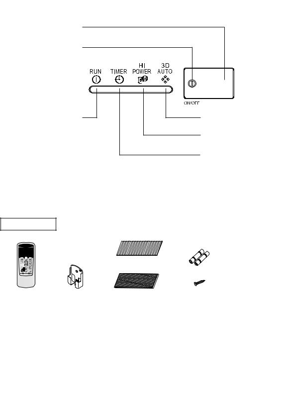
Unit display section
Remote control signal receiver
Unit ON/OFF button
This button can be used for turning on/off the unit when remote control is not available. 
RUN (HOT KEEP) light (green)
•Illuminates during operation.
•Blinks when airflow stops due to the ‘HOT KEEP’ and ‘CLEAN operation’.
1.5 sec.
ON
HOT KEEP
OFF
0.5 sec.
3 sec.
ON
CLEAN operation
OFF
1 sec.
Page 15
3D AUTO light (green)
Illuminates during 3D AUTO operation.
HI POWER light (green)
Illuminates during HIGH POWER operation.
TIMER light (yellow)
Illuminates during TIMER operation.
NOTE
• Buzzer sound for remote control
When preset temperature 24°C, automatic operation and automatic airflow are selected, the buzzer sound (PiPi) is produced. When turning off the air conditioner by pressing ON/OFF button (except CLEAN mode), the buzzer sound (Pi) is produced. This function is useful for operating the air conditioner in the darkness.
|
Air flow setting |
Preset temperature |
|||||||||||||||||||||||||||
– 5 –
Remote control handling
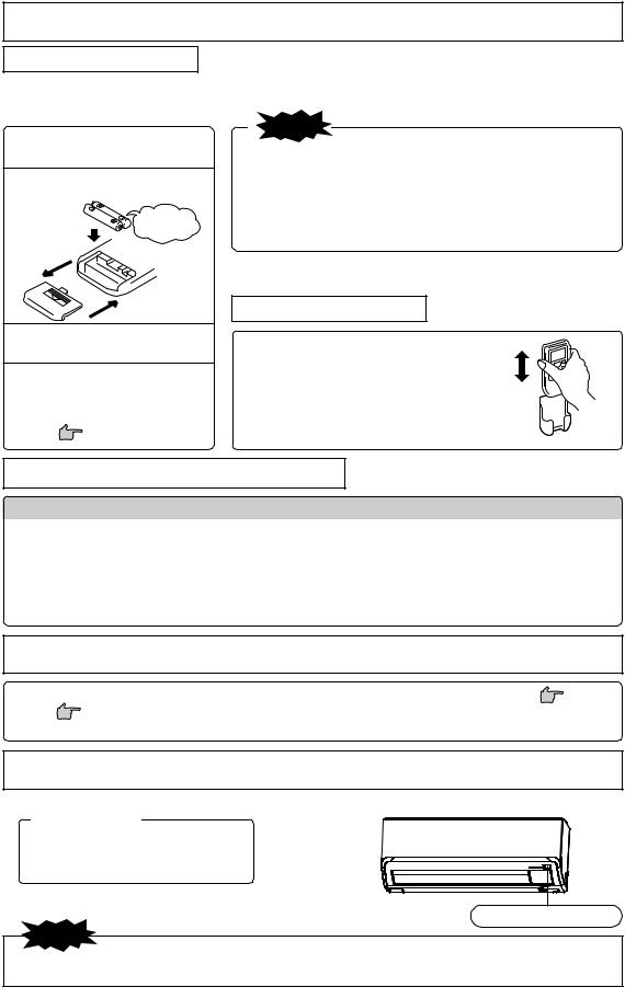
Replacing the batteries
The following cases signify exhausted batteries. Replace old batteries with new ones.
•Receiving beep is not emitted when a signal is transmitted.
•Display fades away.
1 Pull out the cover and take out old batteries.
2 Insert new batteries.
R03 (AAA, Micro) x2
Pay attention to the ª and · marks
3 Close the cover.
4 Press the ACL switch with the tip of a ballpoint pen.
The timer setting mode is displayed.
Page 7
NOTE
•Do not use old and new batteries together.
•Remove the batteries when the remote control is not used for a long period.
•The recommended effective period of a battery conforming to JIS or IEC should be 6 to 12 months with normal use. If used longer, or when an unspecified battery is used, liquid may leak from the battery, causing the remote control to malfunction.
•The recommendable effective period is printed on the battery. This may be shorter due to manufacturering time to the unit. However, the battery may still be in working order after expiry of its nominal life.
■When the display shows any abnormal condition, Press the ACL switch with the tip of a ballpoint pen.
Using the remote control holder
The remote control can be attached to a wall or pillar by using a remote control holder. Before installing the remote control, check that the air-conditioner receives the signals properly.
For installing or removing the remote control, move it up or down in the holder.
Warning note for remote control handling
 Strictly prohibited
|
• Do not go near high temperature |
• Do not leave the remote control ex- |
• Do not drop the remote control. |
|
places, such as an electric carpet |
posed to direct sunlight or other |
Handle with care. |
|
or stove. |
strong lighting. |
|
|
• Do not put any obstructing obsta- |
• Do not spill any liquid on the |
• Do not place heavy objects on the |
|
cles between the remote control |
remote control. |
remote control, or step on it. |
|
and the unit. |
||
Operation failure with the remote control
• Are the batteries running down?
“Replacing the batteries” above.
Replace the batteries with new ones and retry the operation.
|
• If the operation fails, operate the unit with |
Below |
|
temporary operation function. |
|
|
Contact your dealer to have the remote control |
|
|
checked. |
Temporary run operation
• The unit ON/OFF button on the unit operates ON/OFF temporarily when the remote control is not used.
|
Operation program |
|||
|
• |
OPERATION MODE |
: |
AUTO |
|
• |
FAN SPEED |
: |
AUTO |
|
• |
AIR FLOW |
: |
AUTO |
|
• Operation starts by pressing the unit ON/OFF button; it stops if you press |
|||
|
the button again. |
Unit ON/OFF button |
||
|
NOTE |
•Do not hold the Unit ON/OFF button down for more than 5 seconds.
(Holding it down longer than 5 seconds sets the automatic cooling used during servicing or when relocating the air-conditioner.)
–6 –
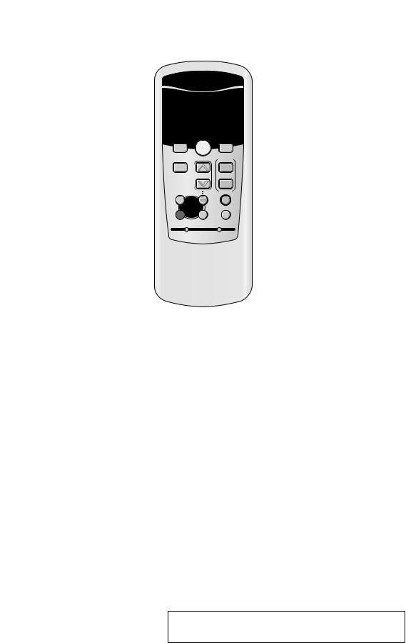
Page 6
Page 10
Operation and display section for remote control
Operation section
FAN SPEED button
Each time the button is pressed, the display is switched over in turn.
Page 8
HI POWER/ECONO button
This button changes the HIGH POWER/ ECONOMY mode.
Page 14
TEMPERATURE button
These buttons set the room temperature. (These buttons are used for setting the current time and timer function as well.)
ON TIMER button
This button selects ON TIMER operation.
Page 12
SLEEP button
This button selects SLEEP operation.
Page 11
CLEAN switch
This switch selects the CLEAN mode.
Page 15
CANCEL button
This button cancels the ON timer, OFF timer, and SLEEP operation.
•The above illustration shows all controls, but in practice only the relevant parts are shown.
Transmission procedure
OPERATION MODE select button
Each time the button pressed, the  display is switched over in turn.
Page 8, 9
ON/OFF (luminous) button
Press to start operation, press again to stop.
AIR FLOW (UP/DOWN) button
This button changes the air flow (up/down)
direction.
Page 10
AIR FLOW (LEFT/RIGHT) button
This button changes the air flow (left/right) direction.
3D AUTO button
This button sets 3D AUTO operation.
Page 10
OFF TIMER button
This button selects OFF TIMER operation.
Page 11
ACL switch
This switch is for resetting microcomputer and setting time.
ALLERGEN CLEAR button
This button selects ALLERGEN CLEAR
operation.
Page 13
When each button on the remote control is pressed – with the remote control pointing towards the air-conditioner unit a signal is transmitted. When the air-conditioner receives the signal correctly, it will beep.
Current time setting
■When inserting the batteries, the current time is automatically set to time setting mode. 13:00 is displayed as the current time. Set the clock to the right time.
Example: Set to 10:30.
1
2
Press the ACL switch.
Press with the tip of a ballpoint pen, etc.
The time display blinks and can be set to the current time.
Press the “ or
or  ” button.
(Set to 10:30)
3 Press the ON/OFF button.
The display changes from blinking to steady lighting and the setting is complete. Make sure to press the button within 60 seconds from the last operation in step 2, otherwise the time is not set.
NOTE
•The timer operation works based on the time clock, so please set it correctly.
•The remote control data is reset when the present time is set.
– 7 –
 Loading…