-
Contents
-
Table of Contents
-
Troubleshooting
-
Bookmarks
Quick Links
TP-202MV
TP-202MVB
(with battery)
SEMI-AUTO
PALLET
TP-202MV
Original Instruction
MINI VERTI
07/2017
Related Manuals for Transpak MINI-VERTI TP-202MV
Summary of Contents for Transpak MINI-VERTI TP-202MV
-
Page 1
SEMI-AUTO PALLET MINI VERTI TP-202MV TP-202MV TP-202MVB (with battery) Original Instruction 07/2017… -
Page 2: Table Of Contents
PART I CONTENTS 1. Safety Instructions …………….1 2. Construction and Units …………… 3 3. General Safety Remarks …………..5 4. Machine Information …………….7 5. Operating the Machine …………… 20 6. Adjustment ………………22 7. Maintenance ………………23 8. Troubleshooting Guide …………..…28 9.
-
Page 3: Safety Instructions
1. Safety Instructions THIS MANUAL GIVES YOU INFORMATION ON SAFETY INSTRUCTIONS, SPECIFICATIONS, OPERATION AND MAINTENANCE OF STRAPPING MACHINES. BEFORE OPERATING OR SERVICING THE MACHINE, PLEASE REVIEW THE ENTIRE MANUAL AND FOLLOW THE SAFETY INSTRUCTIONS CAREFULLY. (1) Before Operating a. Verify that the power line voltage is correct. b.
-
Page 4
(6) Storage a. The store room must be dry. b. Do not expose the machine to extreme cold or heat environment. c. Place the machine on an even floor in order to avoid any distortion. (7) Other Reminders a. Do not alter or bypass protective interlocks. b. -
Page 5: Construction And Units
2. Construction and Units a. TP-202MV 3 Reel unit Holds the strap coil. (If the reel core size is 280mm, you can take off the center drum to have core size 200mm.) 4 Body frame group 2 Bandway unit (Sword unit & RH Bandway ass’y) 5 Electric control unit 1 Strapping head unit This unit is the most important part of the…
-
Page 6
b. TP-202MVB 3 Reel unit Holds the strap coil. (If the reel core size is 280mm, you can take off the center drum to have core size 200mm.) 6 Battery unit 4 Body frame group 2 Bandway unit (Sword unit & RH Bandway ass’y) 5 Electric control unit 1 Strapping head unit This unit is the most important part of the… -
Page 7: General Safety Remarks
3. General Safety Remarks (1) Basic Operation The manual and the safety remarks are to be read before use. The operation manual should be kept with the machine at all times for regular maintenance and inspections. This machine was built with state of the art technology and rigid adherence to safety standards.
-
Page 8
In case of any malfunction the machine must be stopped and locked until the defect has been eliminated. Generally make sure that nobody is at risk before starting up the machine. All personnel that will be operating this machine should be thoroughly trained in all phases of operation and safety. -
Page 9: Machine Information
(5) Grounding Instructions Shall Include the Following: This product must be grounded. In the event of an electrical short circuit, grounding reduces the risk of electric shock. This product is equipped with a cord that has a grounding wire and an appropriate grounding plug. The plug must be plugged into an outlet that is properly installed and grounded in accordance with all local codes and ordinances.
-
Page 10
(2) The Safety Devices This machine must only be operated with polypropylene strapping. The use of other synthetic straps may produce hazardous substances to health. Caution! Power Switch (QS1). This switch is lockable for safety. Danger of burns near the heating unit! (1) Dangerous points in the machine are covered by the screwed table top. -
Page 11
(4) Technical Data a. TP-202MV Sealing method Heat Strap width : 9 mm to 15.5 mm (3/8″ to 5/8″) Strap reel diameter : 200 mm (8″) Strap reel diameter(OPTION) : 280 mm (11″) Width : 696 mm (27.4″) Depth : 2035 mm (80.1″) Electrical Requirement : AC 110V/220V/230V/240V… -
Page 12
b. TP-202MVB Sealing method Heat Strap width : 9 mm to 15.5 mm (3/8″ to 5/8″) Strap reel diameter : 200 mm (8″) Strap reel diameter(OPTION) : 280 mm (11″) Width : 696 mm (27.4″) Depth : 2459 mm (96.8″) Electrical Requirement : AC 110V/220V/230V/240V (50/60Hz), 1PH Weight :… -
Page 13
(5) How to Remove/Handle the Machine from the Pallet Two people stand on each side of the machine and remove the machine from the pallet to the floor. — 11 -… -
Page 14
(6) Machine and Operating Elements a.TP-202MV (1) Power Switch Supply the power when switch is ON. Strap is automatically fed according with the time preset by (2) Feeding Length Knob the knob. (3) Reset Button To pull strap back into machine and/or to cut off strap. To feed strap out of machine manually. -
Page 15
b. TP-202MVB (1) Power Switch Supply the power when switch is ON. Strap is automatically fed according with the time preset (2) Feeding Length Knob by the knob. (3) Reset Button To pull strap back into machine and/or to cut off strap. (4) Strap Feed Button To feed strap out of machine manually. -
Page 16
c. UPS Operation Panel for TP-202MVB (a) Power Switch:It’s to activate UPS. (b) LCD:It shows the potential of the battery. (c) LED:It shows the operation status of UPS. Green light means the power supply of either charging or strapping isn’t from the battery but from the power company. -
Page 17
(7) installation a. TP-201MV (a) Installation of Pushing Bar ○ Please connect the wiring plug of the pushing bar to the terminal of machine. Please refer to the illustration. ○ Put the pushing bar to the 4 M6 screw holes and then hand tighten the 4 sets of bolts (HBS0616N, SW06 &… -
Page 18
○ Also tighten the pushing bar support to the frame with 2 sets of M8 bolts and washers. ○ Tighten the 4 sets of M6 bolts and washers that you just hand tighten on the step 2. ○ After fixing the pushing bar, fasten the power cord with cable clamps and screws TMS0408N on the pushing bar. -
Page 19
(b) Sword Assembling Lock Bandway Ass’y (LH) ○ and Bandway Ass’y (RH) ○ in place by FMS0610 ○ (c) Install the sword to the machine body Fit the sword into the Block ○ at the bottom of the machine until the sword is locked in place. -
Page 20
b. TP-201MVB (a) Installation of Pushing Bar pushing bar ○ Please connect the wiring plug of the pushing bar to the terminal of machine. Please refer to the illustration. ○ Put the pushing bar to the 4 M6 Screw holes and then hand tighten the 4 sets of bolts and washers. -
Page 21
pushing bar ○ After fixing the pushing bar, fasten the power cord with cable clamps and screws TMS0408N on the pushing bar. (b) Sword Assembling Lock Bandway Ass’y (LH) ○ and Bandway Ass’y (RH) ○ in place by FMS0610 ○ (c) Install the sword to the machine body Fit the sword into the Block ○… -
Page 22: Operating The Machine
5. Operating the Machine (1) How to Load P.P Strap Please make sure the power is off before you load the strap in the reel. Step 1 Please pay attention to the direction mark on the Outer Flange ○ . Put a coil of strap into the Inner Flange ○…
-
Page 23
(2) How to Operate a. TP-202MV 1. Turn main switch QS1 to ON. The heating element will reach the working temperature at approximately 2 minute. 2. Push the machine to let the sword unit pass through to the pallet. Have the front plate of the machine close to the package. -
Page 24: Adjustment
6. Adjustment (1) Strap Width Adjustment for strap in different width can be done with screw driver and wrench. The adjustment must be made in Three places, Fig.A. Fig.B. Fig.C. as shown below. For A, the width of band guide should be at 12.5mm when using 9mm and 12mm, strap and the width of band guide should be at 15.5mm when using 15mm strap.
-
Page 25: Maintenance
(2) Outside Tension Adjustment The adjustment is made by tensioning adjustment tube A which is located at the left side of the machine. Tensioning adjustment tube A is turned clockwise to increase the strength and counterclockwise to decrease the strength. 7.
-
Page 26
g. How to replace the battery: (i) Fix 4 terminal brackets (on the wires for the battery) to the positive and negative pole of the battery accordingly. (refer to the illustration) (ii) Connect the UPS and the battery with the connection wire. The shorter wire is to connect the positive and negative pole of the battery. -
Page 27
(2) Disconnect the Sword Unit from machine if it would not be used for a long time. Press the release button ○ located on the right side of the sword to disassemble the sword from the machine. Place the sword to the prearranged place. (3) How to Charge the Battery 1. -
Page 28
(4) Maintenance of the Machine Before any maintenance or repairs on the machine, set the Main Power Switch to «O» (OFF). Wait about 5 minutes for cooling down the heater to avoid burns with this area. 1. Cleaning and Lubrication The high reliability and long service life of the strapping machine will depend on regular cleaning and maintenance. -
Page 29
Monthly or 3,000 strapping cycles) Clean both sides of heater plate and polish with fine sandpaper if necessary. ATTENTION: Make sure the welding plate is cool first!! Check cam rollers of seal head for easy movement. Slide table back to home position automatically by the spring tension.
 -
Page 30: Troubleshooting Guide
8. Troubleshooting Guide (1) Strap Jams in the Groove Step 1. Turn the power switch off and pull out the strap strongly in tensioning direction. Step 2. In case this remedy does not work due to a serious jam, follow the instructions listed below.
-
Page 31
(2) The Strap Does Not Feed Past the Infeed Guide This failure is caused when the front bar is in the raised position (previous cycle has not been completed). Turn the power switch «off «, then «on» again. If this does not eliminate the failure, adjust the lever for LS1 to allow LS1 to be activated and de- activated correctly. -
Page 32: Wiring Diagram
9. Wiring Diagram — 30 -…
-
Page 35
PART II CONTENTS 1. Strapping Head Unit …………………………………………… 1 2. Bandway Unit………………………………………………… 17 3. Reel Unit……………………………………………………… 21 4. Body Frame Group…………………………………………… 25 5. Electric Control Unit ………………………………………… 29 6. Battery Unit ………………………………………………… 34… -
Page 36
STRAPPING HEAD UNIT T2-1-90016 T2-1-90017 REF. PART NO. DESCRIPTION Q’TY REMARKS T2-1-90016 Strapping Head Unit (For 110V, 9mm~12mm) T2-1-90017 Strapping Head Unit (For 110V, 15.5mm) T2-1-90018 Strapping Head Unit (For 220V, 9mm~12mm) T2-1-90019 Strapping Head Unit (For 220V, 15.5mm) T2-1-90020 Strapping Head Unit (For 240V, 9mm~12mm) T2-1-90021… -
Page 37: Strapping Head Unit
STRAPPING HEAD UNIT T2-1-90016 T2-1-90017 REF. PART NO. DESCRIPTION Q’TY REMARKS T2-1-20000 Bracket Gruop (For 110V) SEE PAGE 15 T2-1-20001 Bracket Gruop (For 220V) SEE PAGE 15 T2-1-20002 Bracket Gruop (For 240V) SEE PAGE 15 LA-50082 Label (LS-3) LA-50095 Label (LS-4)
-
Page 38
STRAPPING HEAD GROUP T2-1-10013 T2-1-10014 (1 OF 2) -
Page 39
STRAPPING HEAD GROUP T2-1-10013 T2-1-10014 (1 OF 2) REF. PART NO. DESCRIPTION Q’TY REMARKS T2-1-10013 Strapping Head Group (For 110V, 9mm~12mm) T2-1-10014 Strapping Head Group (For 110V, 15.5mm) T2-1-10017 Strapping Head Group (For 220V~240V, 9mm~12mm) T2-1-10019 Strapping Head Group (For 220V~240V, 15.5mm) T2-1-10010 Guide (R) T2-1-10030… -
Page 40
STRAPPING HEAD GROUP T2-1-10013 T2-1-10014 (1 OF 2) REF. PART NO. DESCRIPTION Q’TY REMARKS TA-027 Sprocket TA-028 Housing TA-029 TA-030 Holder TA-032 Spring TA-033 Stop Arm TA-034 Clutch Arm TA-035 Shaft TA-037 Clutch Support TA-040 Guide TA-042 Gear Box TA-058 Pull Shaft TA-060 Solenoid Shaft… -
Page 41
STRAPPING HEAD GROUP T2-1-10013 T2-1-10014 (1 OF 2) REF. PART NO. DESCRIPTION Q’TY REMARKS TF-002 Micro Switch Brac et TF-006 Micro Switch (LS-1, LS-3) TF-009 Switch Trigger LA-50080 Label LA-50084 Label (SOL-2) TF-071 Varistor TA-241 Spacer T2-1-10200 Cam Ass’y TA-035A Stop Arm Ass’y TA-058A Pull Shaft Ass’y… -
Page 42
STRAPPING HEAD GROUP T2-1-10013 T2-1-10014 (1 OF 2) REF. PART NO. DESCRIPTION Q’TY REMARKS HN03 HN, M3 HN04 HN, M4 HN05 HN, M5 HN06 HN, M6 HN08 HN, M8 HSS0506G HSS, M5x6 (G) HSS0606G HSS, M6x6 (G) HSS0608G HSS, M6x8 (G) KYA0505101 Key, 5x5x101 KYA050515 Key, 5x5x15… -
Page 44
STRAPPING HEAD GROUP T2-1-10013 T2-1-10014 (2 OF 2) REF. PART NO. DESCRIPTION Q’TY REMARKS T2-1-10060 Holder Arm T2-1-10082 Outlet Cover T2-1-10071 Outlet Guide T2-1-10090 Bracket T2-1-10101 Bracket Sub Ass’y T2-1-10110 T2-1-10120 Heater Arm T2-1-10130 Bracket T2-1-10140 Bandway (For 9mm~12mm) T2-1-10141 Bandway (For 15mm) T2-1-10172 Holder… -
Page 45
STRAPPING HEAD GROUP T2-1-10013 T2-1-10014 (2 OF 2) REF. PART NO. DESCRIPTION Q’TY REMARKS TB-154 Spring TB-162 Shaft TB-164 Shaft TB-165 Feed Arm TB-168 Arm Pin TB-170 Pulley TB-175 Plate TB-175A Plate TB-176 Friction Disc TB-177 Pull Shaft TB-183 Spring TB-184 Stop Bracket TB-186… -
Page 46
STRAPPING HEAD GROUP T2-1-10013 T2-1-10014 (2 OF 2) REF. PART NO. DESCRIPTION Q’TY REMARKS T2-1-10182 Roller Holder Ass’y T2-1-10232 Brac et Ass’y TB-165A Feed Arm Ass’y TB-170A Pulley Ass’y TB-177A Pull Shaft Ass’y FMS0412 FMS, M4x12 BR6002ZZ Bearing, 6002ZZ BR635ZZ Bearing, 635ZZ ER06 Snap Ring, E-6… -
Page 47
STRAPPING HEAD GROUP T2-1-10013 T2-1-10014 (2 OF 2) REF. PART NO. DESCRIPTION Q’TY REMARKS KYA050515 Key, 5x5x15 KYA050520 Key, 5x5x20 KYA050538 Key, 5x5x38 PMS0410 PMS, M4x10 PMS0412 PMS, M4x12 PW04 PW, M4 PW05 PW, M5 PW06A PW, M6 (A) RR32 Snap Ring, H-32 SP0414 Spring Pin, 4×14… -
Page 48
TUBE ASS’Y 1-1-1 T2-1-11000 REF. Q’TY PART NO. DESCRIPTION REMARKS T2-1-10150 Bolt TB-223 Washer TB-248 Spring Retainer TB-250 Tube A TB-251 Tube B TB-263 Tube TB-264 Tension Adjusting Ass’y SR40 Snap Ring, S-40 BR6002ZZ Bearing, 6002ZZ BR6005ZZ Bearing, 6005ZZ HBS0512 HBS, M5×12 HN05 HN, M5… -
Page 49
ROLLER BRACKET ASS’Y 1-1-2 T2-1-12000 REF. Q’TY PART NO. DESCRIPTION REMARKS TB-139 Pulley TB-144 Shaft TB-146 T2-1-12110 Brac et TB-152 Shaft TB-210 Pulley TB-215 Collar T7-3-40480 Spring TF-007 Micro Switch (LS-2) LA-50081 Label (LS-2) BR608ZZ Bearing, 608ZZ BR635ZZ Bearing, 635ZZ ER06 Snap Ring, E-6 HBS0525H… -
Page 50
BRACKET GROUP T2-1-20000 T2-1-20001… -
Page 51
BRACKET GROUP T2-1-20000 T2-1-20001 REF. PART NO. DESCRIPTION Q’TY REMARKS T2-1-20000 Brac et Gruop (For 110V) T2-1-20001 Brac et Gruop (For 220V) T2-1-20002 Brac et Gruop (For 240V) T2-1-20010 Belt TA-020 Pulley TB-137 Shaft TB-141 Pulley TB-157 V-Belt TB-160 Brac et TB-173 V-Belt TB-231… -
Page 54
SWORD GROUP T2-2-10000 REF. PART NO. DESCRIPTION Q’TY REMARKS T2-2-10010 Bandway Hoo T2-2-10020 Rear Bandway Rac T2-2-10030 RH Bandway Ass’y T2-2-10100 LH Bandway Ass’y T2-2-10150 Front Bandway Rac T6-2-11140 RH Bandway Flap Pin (Rear) T6-2-11150 RH Bandway Flap Spring T6-2-11160 RH Bandway Flap Pin (Front) T7-1-10310 Spring… -
Page 55
RH BANDWAY ASS’Y T6-2-11000 T6-2-11001 REF. PART NO. DESCRIPTION Q’TY REMARKS T6-2-11000 RH Bandway Ass’y (For 12mm) T6-2-11001 RH Bandway Ass’y (For 9mm) T6-2-11002 RH Bandway Ass’y (For 15.5mm) T6-2-11140 RH Bandway Flap Pin (Rear) T6-2-11150 RH Bandway Flap Spring T6-2-11160 RH Bandway Flap Pin (Front) -20-… -
Page 56: Reel Unit
REEL UNIT T2-4-90002 REF. PART NO. DESCRIPTION Q’TY REMARKS T6-4-20002 Reel Control Group (For 200mm) SEE PAGE 22 TL-023 Stopper TL-024 Bolt HN08 HN, M8 SW08 SW, M8 PW08C PW, M8 (C) -21-…
-
Page 57
REEL CONROL GROUP T6-4-20002… -
Page 58
REEL CONTROL GROUP T6-4-20002 REF. PART NO. DESCRIPTION Q’TY REMARKS T6-4-20011 Reel Support T6-4-20029 Bra e Belt T6-4-20031 Lining Fixed Brac et T6-4-20024 Bra e Arm TC-005 TC-009 Bra e Shaft TC-011 Washer T6-4-10570 Inner Flange TC-014 Outer Flange TC-015 Protector TC-020 TC-021… -
Page 59
REEL CONTROL GROUP T6-4-20002 REF. PART NO. DESCRIPTION Q’TY REMARKS BR6003ZZ Bearing, 6003ZZ ER04 Snap Ring, E-4 ER19 Snap Ring, E-19 HB0816 HB, M8x16 HBS0525H HBS, M5x25 (H) HBS0616 HBS, M6x16 HBS0825 HBS, M8x25 HN05 HN, M5 HN06 HN, M6 SW08 SW, M8 PW08C… -
Page 60
BODY FRAME GROUP T2-5-10320 T2-5-10330 REF. Q’TY PART NO. DESCRIPTION REMARKS T2-5-10320 Body Frame Group (For TP-202MV) SEE PAGE 25 SEE PAGE 25 T2-5-10330 Body Frame Group (For TP-202MVB) -25-… -
Page 61
BODY FRAME GROUP T2-5-10320 T2-5-10330… -
Page 62
BODY FRAME GROUP T2-5-10320 T2-5-10330 REF. PART NO. DESCRIPTION Q’TY REMARKS T2-5-10320 Body Frame Group (For TP-202MV) T2-5-10330 Body Frame Group (For TP-202MVB) T2-5-10011 Body Frame T2-5-10020 Front Plate (LH) T2-5-10030 Front Plate (RH) T2-5-10040 Brac et T2-5-10051 Plate (RH) T2-5-10061 Plate (LH) T2-5-10250… -
Page 63: Body Frame Group
BODY FRAME GROUP T2-5-10320 T2-5-10330 REF. PART NO. DESCRIPTION Q’TY REMARKS SW08 SW, M8 (Only TP-202MV) PW08C PW, M8 (C)(Only TP-202MV) PW06A PW, M6 (A)(Only TP-202MV) HN5/8 HN, 5/8″ SW16 SW, M16 -28-…
-
Page 64: Electric Control Unit
ELECTRIC CONTROL UNIT T2-6-90001 T2-6-90003 REF. Q’TY PART NO. DESCRIPTION REMARKS T2-6-90001 Control Group (For 110V) T2-6-90003 Control Group (For 220V) T2-6-90004 Control Group (For 240V) T2-6-10002 Heater Transformer Ass’y SEE PAGE 30 (For 110V, TP-202MV) SEE PAGE 30 T2-6-10003 Heater Transformer Ass’y (For 220V/230V/240V, TP-202MV) SEE PAGE 30…
-
Page 65
HEATER TRANSFORMER ASS’Y T2-6-10002 T2-6-10003… -
Page 66
HEATER TRANSFORMER ASS’Y T2-6-10002 T2-6-10003 REF. PART NO. DESCRIPTION Q’TY REMARKS T2-6-10002 Heater Transformer Ass’y (For 110V, TP-202MV) T2-6-10003 Heater Transformer Ass’y (For 220V/230V/240V, TP-202MV) T2-6-10011 Heater Transformer Ass’y (For 110V, TP-202MVB) T2-6-10012 Heater Transformer Ass’y (For 220V/230V/240V, TP-202MVB) T2-6-10010 Tube Plug T2-6-10020 Wire Ass’y (For TP-202MV) -
Page 67
ELECTRIC GROUP T2-6-20003 T2-6-20004… -
Page 68
ELECTRIC GROUP T2-6-20003 T2-6-20004 REF. PART NO. DESCRIPTION Q’TY REMARKS T2-6-20003 Electric Group (For 110V) T2-6-20004 Electric Group (For 220V) T2-6-20005 Electric Group (For 240V) T2-6-20011 Control Plate T6-6-10980 Cable Gland (PG11) T6-6-30133 Fuse (10A) 30L (For 110V AC) T6-6-30034 Fuse (7A) 30L (For 220V/230V/240V MV-6-10060 Power Cord (Europe Plug) -
Page 69: Battery Unit
BATTERY UNIT T2-6-90007 (For TP-202MVB) REF. PART NO. DESCRIPTION Q’TY REMARKS T2-6-40000 Battery Group (For 220V/230V/240V) SEE PAGE 36 T2-6-40001 Battery Group (For 110V) SEE PAGE 36 -34-…
-
Page 70
BATTERY GROUP T2-6-40000 (For TP-202MVB) T2-6-40001… -
Page 71
BATTERY GROUP T2-6-40000 (For TP-202MVB) T2-6-40001 REF. PART NO. DESCRIPTION Q’TY REMARKS T2-6-40000 Battery Group (For 220V/230V/240V) T2-6-40001 Battery Group (For 110V) HB08230 HB, M8×230 T2-6-30211 Battery (VRLA) T2-6-30220 UPS (For 110V) T2-6-30221 UPS (For 220V/230V/240V) UPS Cable (Europe) T2-6-30240 T2-6-30241 UPS Cable (America) T2-6-30261… -
Page 72
BATTERY GROUP T2-6-40000 (For TP-202MVB) T2-6-40001 REF. PART NO. DESCRIPTION Q’TY REMARKS SW04 SW, M4 SW06 SW, M6 SW10 SW, M10 SW08 SW, M8 T2-6-30331 Battery Contact Insulation Sheath (Positive) T2-6-30341 Battery Contact Insulation Sheath (Negative) HBS0612N HBS, M6x12 (N) HBS0820N HBS, M8x20 (N) HBS0616N…
Описание и принцип работы:
Полуавтоматическая стреппинг машина SP A2H – это аналог легендарной ТР-201, такая же простая в управлении и поэтому дешевая в эксплуатации. Регулируемый выброс ленты позволяет упаковывать любой по габаритам товар, который можно разместить на столе.
Упаковочный стол настраивается по трем регулеровкам: сила натяжения ленты, температура нагревательного элемента и длина выброса ленты.
Принцип работы полуавтоматической машины:
Ставим товар на стол машины по центру прорези (линия упаковки),
Машина автоматически выбрасывает ленту на рабочий стол на заданную длину
Свободным концом обводим через товар и вставляем в приемное устройство машины
Машина автоматически натянет, скрепит ленту с помощью вибросварки и обрежет ленту, осталось убрать упакованный товар со стола.
Оплата: физические и юридические лица. Доставка: самовывоз или средствами нашей компании. Бесплатно по Москве внутри МКАД узнать можно в разделе «Бесплатная доставка»
Стреппинг машина ТР-202 — Характеристики
| Модель | ТР-202 |
| Тип устройства | Электрический |
| Вид устройства | полуавтоматическ |
| Ширина скрепляемой ленты | 9 мм, 10 мм, 12 мм, 13 мм, 15 мм |
| Эффективность сварки | 75-90 % |
| Максимальная сила скрепления | 15-45 кг |
| Внутренний диаметр бухты ленты | 200/280 мм |
| Длина | 902 |
| Высота | 760 |
| Ширина | 586 |
| Вес | 80 кг |
| Производство | Китай |
Стреппинг машина ТР-202 отзывы
Отзывов об этом товаре пока нет. Будьте первым!
 Загрузка данных авторизации
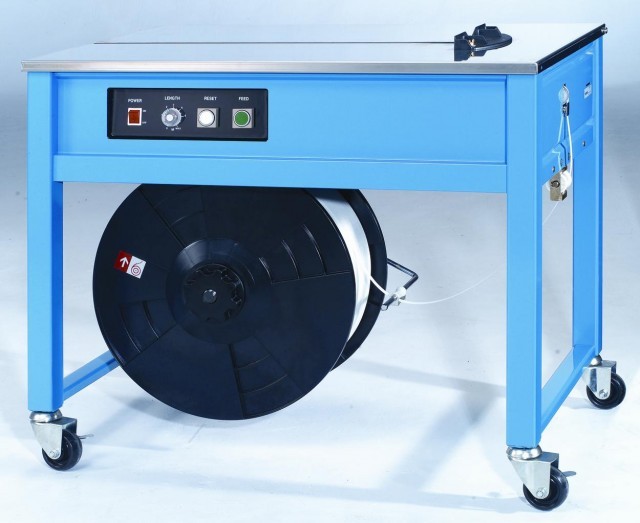
Стреппинг машина ТР-202 полуавтоматическая модель с открытым корпусом.
Запчасти для ТР-202, 201, 203, TP-202L
Данная модель легко перенастраивается на необходимый размер полипропиленовой ленты шириной от 6мм до 15мм.
1. Механизм после каждого цикла самостоятельно выбрасывает ленту на заранее выставленную длину
2. Оператор устанавливает продукт на рабочий стол машины;
3. Обводит ленту вокруг упаковываемого продукта и помещает в приемный механизм
4. Машина автоматически производит стяжку, запайку и обрезание ленты.
Товар в наличии
|
Технические данные ТР-202 |
|
|
Время упаковки ТР-202 |
2,5 сек/обв. |
|
Размер стреппинг ленты |
6÷15,5 мм |
|
Установка момента натяжения стреппинг ленты |
механическое |
|
Усилие натяжения ленты мах |
45кг |
|
Размер упаковываемого предмета: |
|
|
мин |
120 х 30 мм |
|
мах |
не ограничен |
|
Напряжение питания |
220 В (50 Гц) |
|
Мощность |
200 Вт |
|
внешний диаметр диспенсера для ленты |
200мм |
|
Вес стреппинг машины ТР-201 |
100кг |
|
Размеры в рабочем виде |
910мм (д) X 582мм (ш) X 785мм (в) |
Преимущества ТР-202
(1) Мобильность
Эта машина компактна и легка
при транспортировке и требует малого пространства для установки.
(2) Управление двигателем
На машине установлен один привод (двигатель). Устойчивая работа которого гарантирована даже при значительном изменении напряжения.
(3) Легкая подстройка к изменению ширины ленты
Подстройка к использования любой ленты шириной до 15.5mm может быть сделана, регулировкой только четырех винтов.
(4) Никакого повреждения ленты
Подающаяся система, связывающе-натяжное устройство и кулачки так разработаны, что не допускают расщепления, изгибов, изломов и царапания.
(5) Применима к любым формам
Небольшая ширина стола и малое скольжение, позволяют выполнять простое связывание разных по форме предметов.
(6) Простота в управлении
Свободный конец ленты появляется на столе, который обводиться вокруг изделия вручную для связывания. Никакого специального обучения не требуется.
(7) Простота в обслуживании
Легкая при необходимости замена стола. В машине применяется быстро нагревающаяся пластина, позволяя быстрое включение. Также эта машина оборудована двумя выключателями, которые помогают освобождать ленту при замятии её и помогают в случае отказа любых микро выключателей. Машина может использоваться в этом случае, пока микровыключатели или лента не восстановлены, повторно исправлены или очищены.