-
Bookmarks
Quick Links
Adjustable Frequency
A.C. Motor Drive
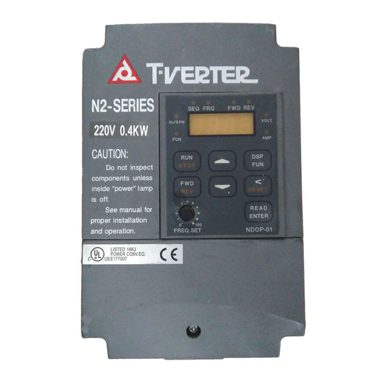
N2-220V
N2-440V
N2 Series
0.4~22KW
( 1.2~33.2KVA )
0.75~22KW
( 1.7~36.6KVA )
Related Manuals for TECO T-verter N2 Series
Summary of Contents for TECO T-verter N2 Series
-
Page 1
N2 Series Adjustable Frequency A.C. Motor Drive N2-220V 0.4~22KW ( 1.2~33.2KVA ) N2-440V 0.75~22KW ( 1.7~36.6KVA ) -
Page 2
Operations Manual Table of Contents Foreword………………..1 Precautions for Operation ……………. 2 Operational Environment …………….. 6 General Introduction …………….7 Specifications………………. 9 Wiring Rules………………. 11 Keypad Operations …………….21 Parameter List………………22 Functional Description …………….30 Failure Codes………………60 Maintenance Section …………….65 Filters ………………… -
Page 3
Distributor ., 49, Wu Kong 6Rd. Wu-Ku Industrial Park, Taipei County 248, Taiwan This manual may be modified when necessary because of improvement of the product, modification, or changes in specifications. This manual is subject to change without notice. 4KA72X026T01 Ver:06 2005.09… -
Page 4
Foreword To fully employ all functions of this T-verter and to ensure the safety for its users, please read through this operations manual in detail. Should you have any further questions, please feel free to contact your local distributor or regional representative. PLEASE READ AND UNDERSTAND THIS MANUAL BEFORE OPERATING THIS T-VERTER The T-verter is a power electronic device. -
Page 5
Precautions for operation Examination before installation Every T-verter has been fully tested and examined before shipment. Please carry out the following examination procedures after unpacking your T-verter. Check to see if the model number of the T-verter matches the model number of the T-verter that you ordered. -
Page 6
When power is applied WARNING Do not attempt to install or remove input or out put connectors of T-verter when the power supply is turned on. Otherwise, the T-verter may be damaged due to the surge peak caused by the insertion or removal. Under Operation WARNING Do not use a separate device to switch ON or OFF motor during operation. -
Page 7
CAUTION Do not touch the heat-sink base during operation. The T-verter can be easily operated from a low-speed to high-speed range. Please reconfirm the operating range of motor and the machinery you are controlling. Do not examining the signals on the PCB of the T-verter when it is under operation. All T-verters are properly adjusted and set before delivery. -
Page 8
Taking Precautions: Avoid any direct sunlight Keep away from Keep away from oil corrosive gas or liquid grease and gas Keep away from rain or Avoid metal dust and Keep away from salty where dripping water may dusty environments environments get into the T-verter Avoid where Avoid massive vibration… -
Page 9
Operational Environment The installation site of the T-verter is very important. It relates directly to the functionality and the life span of your T-verter. Please carefully choose the installation site to meet the following requirements: Mount the unit vertically Environment temperature: -10 C ~ +40 C(with cover removed: -10 C ~ +50… -
Page 10
General Introduction: General T-verter N2 series is a high performance general-purpose inverter that incorporates a high efficiency Pulse Width Modulated (PWM) design and advanced IGBT technology. The output closely approximates a sinusoidal current waveform to allow variable speed control of any conventional squirrel cage induction motor. -
Page 11
Installation: Location Picking the proper installation location for the T-verter is imperative in order to achieve the maximum specified performance & operation from the Drive. The T-verter should always be installed in areas where the following conditions exist. Good ambient operating temperature: -10 to 40 ℃… -
Page 12
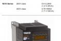
Basic Specification: Mode No. Identification N2 — Series Input Voltage Capacity Specification Phase of input power Enclosure 2 : 200V Class P5 : 0.5Hp M : Standard type Blank : 1/3 phase Blank : IP20 4 : 400V Class H : Advanced type 3 : 3 phase N4 : IP65(NEMA4) 30 : 30Hp 1/ 3 Phase 200-240 Volts… -
Page 13
Functional Specification: Carrier frequency 1 — 12 K Frequency Control Range 0.1 – 400 Hz Digital: 0.01% (-10 ~ 40 °C); Analog: 0.4% (25+-10 °C) Frequency Accuracy Frequency Resolution 0.01 Hz with computer or PLC control, 0.1 Hz with keypad control when freq. above 100 Hz Frequency Setting Signal (0-5VDC) (0-10VDC) (4-20mA) (0-20mA) -
Page 14
Wiring Rules: Notice for wiring Screwdriver torque: Connect cables with a screwdriver or other tools and follow the torque listed below. Securing torque Horsepower Power source Max. Nominal torque for TM1 terminal 0.5/1/2/3 200 – 240V 1.33 lbs.-ft 16 lbs.-in 380 –… -
Page 15
Horsepower Power source Max. Volts Amps 0.5/1/2/3 200 – 240V 380 – 480V 5/7.5/10 200 –240V 3/5/7.5/10 380 –480V 15/20 200 –240V 15/20/25/30 380 –480V 25/30 200 –240V Note: Nominal values of input and output signals (TM2) – follow the specifications of class 2 wiring. -
Page 16
Use the circuit properly, and the carrying current does not exceed 5000 Arms. The maximum output voltage is 240V for 200 – 240V models when carrying current is below 5000 Arms. We cannot guarantee safety for over-speed or similar situations. Do not connect the inverter to a controller or similar devices with current restraint function. -
Page 17
N2-230 model N2-220 MCCB made TO-50E TO-50E TO-50E TO-50E TO-50E TO-50E TO-100S TO-100S TO-225S 100A 175A by Teco MC made by CN-11 CN-16 CN-18 CN-25 CN-50 CN-65 CN-100 CN-100 Teco Wire Wire Wire gauge Wire gauge Wire gauge gauge gauge… -
Page 18
▓ Precautions for peripheral applications: Power source: Make sure the voltage applied is correct to avoid damaging Power the inverter. A molded-case circuit breaker must be installed between the AC source and the inverter. Molded-case circuit breaker: Molded-case Use a molded-case circuit breaker that conforms to the rated voltage and current of the inverter to control the power ON/OFF and protect the inverter. -
Page 19
Make external connections according to the following instruction. Check connections after wiring to make sure all connections are correct. (Do not use the control circuit buzzer to check connections) (A) Main circuit’s wiring must separate from other high voltage or high current power line to avoid noise interference. -
Page 20
When the connection between the inverter and the motor is too long, consider the voltage drop of the circuit. Phase-to-phase voltage drop (V) = 3 ×resistance of wire (Ω/km)×length of line (m)×current×10 . And the number of carriers must be adjusted based on the length of the line. -
Page 21
Wiring & Remote Control Functions: Internal Connections Braking Resistor Reactor AC POWER SUPPLY *4 R(N) Thermal Overload Relay MCCB Ο Ο T1 (U) L1 (R) Ο Ο T2 (V) L2 (S) Ο Ο T3 (W) L3 (T) Thermal Relay RS232 / 485 CON12 CONNECTOR *1 Surge Absorber… -
Page 22
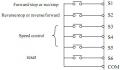
General Wiring Instructions: Note: The drive can be completely controlled by the Keypad, if you chose to use the TM2 control terminal strip, please see the following instructions. Control Connections Terminal 1 TRIP 2 RELAY FWD REV COM SP1 SP2 SP3 RESET SYN- SYN+ + — FM- FM+ Reset Frequency Meter… -
Page 23
Functional description for the main circuit power terminals (TM1) SYMBOL FUNCTION DESCRIPTION L1 (R) Input terminals of AC line power: L2 (S) Single phase: L1 / L2 L3 (T) Three phases: L1 / L2 / L3 P, R External Braking Resistor Terminals, for 1/2~10Hp used only. P1, P External DC Reactor Terminals, for 15~30Hp used only. -
Page 24
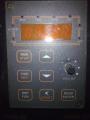
Keypad Operations: Keypad Illustration Freq. ref. controlled by TM2 or VR Forward run (Fn_11=1/2/3) Ο Ο Ο Ο RUN/STOP signal is on Reverse run (Fn_10 =1) SEQ FRQ FWD REV Ο Ο DISPLAY Hz OR Display voltage value Hz/RPM VOLT Ο… -
Page 25
Parameter List Factory Function Description Set Unit Range Page Setting Drive Capacity Drive Capacity Selection 1-40 Accel. Time Accel. Time 1 0.1 sec 0.1-3600 sec 10 sec*1 30 Decel. Time Decel. Time 1 0.1 sec 0.1-3600 sec 10 sec*1 30 xx00 : FWD/STOP, REV/STOP xx01 : FWD/REV, RUN/STOP xx10 : 3 wire Start / Stop Control… -
Page 26
Factory Function Description Set Unit Range Page Setting xxx0 : Stall prevention during accel. enable xxx1 : Stall prevention during accel. disable xx0x : Stall prevention during decel. enable xx1x : Stall prevention during decel. disable 0000 x0xx : Stall prevention during running enable x1xx : Stall prevention during running disable Stall Prevention 0xxx : Stall prevention decel. -
Page 27
Factory Function Description Set Unit Range Page Setting Momentary Power 31 Momentary power loss ride through time 0.1 sec 0-2 sec 0.5 sec Loss Ride Through 32 xxx0 : Disable xxx1 : Enable Analog command 33 Tm2 terminal 13 Analog input 1-100 Scan Time Scan time… -
Page 28
Function Description Set Unit Range Factory Page Setting xxx0 : Enhanced braking capacity xxx1 : Standard braking capacity Dynamic braking xx0x : STOP key effective in remote control mode & Priority of xx1x : STOP key ineffective in remote control mode Stopping &… -
Page 29
Function Description Set Unit Range Factory Page Setting 00: Run mode 01: At Target Speed 02: Set Frequency (Fn_08/09) Multi-function Multi-output 1 03 Frequency Detection > (Fn_08) output (terminal 10 & 11) 04 Frequency Detection < (Fn_08) 05 Over Current Detection 06 Change 00-05 (NO) to (NC) 62 Reserved for future use 63 Reserved for future use… -
Page 30
Function Description Set Unit Range Factory Page Setting Torque boost 72 Torque Boost gain 0.1 % 0.0-10.0 % 0.0 %*1 Reserved for future use 75 Motor current without load 0.1A Specs Slip compensation 0.00- 6.00 0.00 76 Motor rated slip 0.01 Hz Hz*1 77 xxx0 : Over-torque detection disable… -
Page 31
Factory Function Description Set Unit Range Page Setting 92 Vibration control times 1-100 5[30]*1 Vibration 93 Vibration control gain 0.1 % 0-100 % [10%]*1 Control 94 Vibration control bias 0-30 % 0 %*1 Parameters for factory adjustment, Factory adjustment Do Not Change. 97 xxx0 : Fault contact is not energized during auto restart operation xxx1 : Fault contact is energized during auto restart operation xx0x : Fault contact is not energized during momentary power loss… -
Page 32
Factory Function Description Set Unit Range Page Setting Parameter xxx0 : 1 stop bit xxx1 : 2 stop bits Control for xx0x : Even parity xx1x : Odd parity 1100 Communication x0xx : With parity x1xx : Without parity *2 *3 0xxx : 8 bits data 1xxx : 7 bits data 103~… -
Page 33
Function Description Fn_00: Drive Capacity Selection = 1 — 40 Fn_00 MODEL NO Fn_00 MODEL NO N2-2P5 N2-401 N2-201 N2-402 N2-202 N2-403 N2-203 N2-405 N2-205 N2-408 N2-208 N2-410 N2-210 N2-415 N2-215 N2-420 N2-220 N2-430 N2-230 Fn_01: Acceleration Time = 0.1 ~ 3600 Sec. Acceleration time means the time it takes the drive to go from 0 speed to target speed. -
Page 34
Fn_03 Start / Stop Control From Terminal 2 Fn-03: Start / Stop Control for Remote Operation xx00 : FWD/STOP, REV/STOP xx01 : FWD/REV, RUN/STOP xx10 : 3 wire control x0xx : REV command enable x1xx : REV command disable 0xxx : During Fn_11=3 ( TM-2 up & down control), The setting frequency will remain at the last operational frequency when stopped. -
Page 35
Fn_04 Parameter Lockout: Parameter Lock Select xxx0 : Disable (Fn_17-25) xx01 : Enable (Fn_17-25) xx0x : Disable (Functions except Fn_17-25) xx1x : Enable (Functions except Fn_17-25) Fn_05 V/F Pattern Setting / Custom or Preprogrammed: V/F Pattern selection = 0 –18 See next page Fn_30 : Voltage of power supply =200 — 480V Fn_37 : Maximum frequency… -
Page 36
Fn_05 = 0 — 17 V/F Curves Fn_05 50Hz Fn_05 60Hz 100% 100% General Purpose 0.1 2.5 50 0.1 3 60 400 100% 100% High Starting Torque 0.1 2.5 50 400 0.1 3 60 400 100% 100% Variable Torque Operation 25 50 400 100% 100%… -
Page 37
Fn_05 Fn_05 Fn_05 6.5% 6.5% 3/12 9.5% 4.9% 6/15 10.0% 5.1% 215~230 1/10 7.5% 6.1% 4/13 20.0% 6.1% 7/16 12.0% 4.7% 415~430 2/11 8.5% 5.5% 5/14 25.0% 5.8% 8/17 14.0% 4.2% Fn_06 Upper Frequency Limit You can adjust the maximum speed of the motor by raising the Upper Frequency limit at (Fn_06) Fn_07 Lower Frequency Limit You can set the minimum speed for the motor by adjusting the Lower frequency Limit at (Fn_07) 100%… -
Page 38
Fn_10: Start / Stop Control This parameter is used to decide if the Start and Stop function will be controlled by the Keypad or remote control TM2 (terminal 3 / 4). 0 : Keypad control 1 : Remote control TM2 (terminal 3 / 4 ) Note: When Fn_10=1, please refer to the descriptions of Fn_31/32/34/35, in order to avoid the damage to the human and the machine. -
Page 39
Fn_12: Stall Prevention xxx0 : Stall prevention during Acceleration Enable xxx1 : Stall prevention during Acceleration Disable xx0x : Stall prevention during Deceleration Enable xx1x : Stall prevention during Deceleration Disable x0xx : Stall prevention during Running Enable x1xx : Stall prevention during Running Disable 0xxx : Stall prevention Decel. -
Page 40
Fn_16: Direct Start / Scanning / Reset Options xxx0: Direct start enable when remote RUN command is ON xxx1: Direct start disable when remote RUN command is ON xx0x: Reset effective only if remote RUN command is OFF xx1x: Reset effective regardless of the remote RUN command condition 00xx: TM2 terminal will scan 10 times 01xx: TM2 terminal will scan 5 times 10xx: TM2 terminal will scan 3 times… -
Page 41
Fn_24: Jog Speed Reference = 0 — 400 Hz Fn_25: Master Speed Reference from Keypad = 0 — 400 Hz. Note: 1. The T-verter will be operating under the Jog Speed function at (Fn_24) you can assign either (Fn_56) (Fn_57) or (Fn_58) to handle the jog function. 2. -
Page 42
Fn_26: Frequency Reference: 400 Hz Fn_27: Voltage Reference Ratio 1: 100% Fn_28: Voltage Reference Ratio 2: 999.9% Fn_29: Positive or Negative Direction 0: Positive 1: Negative Fn_06 Fn_06 Internal Internal Signal signal Fn_26 Fn_26 Fn_27 100% Fn_27 100% Fn_28 Fn_28 % of frequency setting signal % of frequency setting signal Curves… -
Page 43
Fn_30: Input Voltage Selection Fn_31: Momentary power loss ride through time: 0 — 2 sec Fn_32: Auto-restart after momentary power Loss xxx0: Auto-restart disabled xxx1: Auto-restart enabled Inverter will stop when the voltage is lower than the low voltage protection level. The Inverter can restart automatically by using the speed search function. -
Page 44
Fn_34: Auto Restart Interval: 0.1 ~ 800 sec Fn_35: Number of Auto Restart Attempts (0 -10) times 1. When Fn_35=0, the inverter will not auto-restart after a malfunction break away from operation. (Except for momentary power loss, please refer to Fn_31/32 for details) 2. -
Page 45
Fn_37: Maximum Frequency 0.01 Hz 50 to 400 Hz Fn_38: Maximum Voltage Ratio 0.1 % 0 to 100 % Fn_39: Middle Frequency 0.01 Hz 0.11 to 400 Hz Fn_40: Middle Voltage 0.1 % 0 to 100 % Fn_41: Minimum Voltage Ratio 0.1 % 0 to 100 % In order to build Custom V/Hz Patterns, (Fn_05) must be set at 18. -
Page 46
Fn_44: Stopping Mode and Braking Resistor Protection xxx0 : Decel. to stop xxx1 : Free fun to stop xx0x : Braking resistor overheat protection disable xx1x : Braking resistor overheat protection enable Note: If the (Fn_44) is set at free run to stop, the T-verter will cut off the output after receiving a stop instruction and the motor will coast to a stop. -
Page 47
Fn_48: Dynamic Braking, Priority Stopping, Speed Search and AVR Control xxx0: Enhanced braking capacity. xxx1: Standard braking capacity xx0x: Stop key effective in remote control mode xx1x: Stop key ineffective in remote control mode x0xx: Speed search controlled by terminals on TM2 x1xx: Speed search effective when T-verter start 0xxx:… -
Page 48
Fn_51: Display Mode Selection 1 ~ 5 The Display contents can be switched back and forth using the key either in the run mode or stop mode. Frequency/ RPM / Line speed (Mode set by (Fn_51) Fxxx (Parameters setting mode: refer to digital operator illustration) Output voltage DC voltage (Output voltage, DC voltage… -
Page 49
00 : SP1 (Multi-speed 1) Please refer to (Fn_17) 01 : SP2 (Multi-speed 2) Please refer to (Fn_17) 02 : SP3 (Multi-speed 3) Please refer to (Fn_17) 03 : Jog operation Please refer to (Fn_17) 04 : Accel. / Decel. Time selection Please refer to (Fn_01) 05 : External Emergency Stop 06 : External Base Block Command… -
Page 50
09 Control signal selection Multi-input terminal OFF: Operation command/ Freq command is from digital operator or remote control (TM2), according to the setting of Fn_10 / Fn_11 Multi-input terminal ON: Operation command/ Freq command is from digital operator regardless of the setting of Fn_10 / Fn_11 10 Communication control mode selection Multi-input terminal OFF: During communication, Inverter can receive Rnu/Freq signals from control unit (PC or PLC), Parameter can be changed by control unit, Run/Freq signals from… -
Page 51
12 /13 UP / DOWN command DOWN Output frequency Fn_25 Note: To utilize the up and down function (Fn_11) must be set to terminal control. When using this function set (Fn_03) to the (0xxx) position. The T-verter will accelerate to the target frequency set at (Fn_25) after the designated terminal is turned on, the drive will remain at what ever speed it was at when the contact terminal was released. -
Page 52
Fn_65: Skip Frequency 1 0.01 Hz ~ 0 to 400 Hz Fn_66: Skip Frequency 2 0.01 Hz ~ 0 to 400 Hz Fn_67: Skip Frequency 3 0.01 Hz ~ 0 to 400 Hz Fn_68: Frequency Band Width 0.01 Hz ~ 0 to 10 Hz Example: When (Fn_65) is set at 10.0 Hz, (Fn_66) is set at 20.0 Hz, (Fn_67) is at 30.0 Hz, (Fn_68) -
Page 53
2. When the motors output current exceeds 103%, of the motors protective electronic thermal characteristics during the start operation. The T-verters protective (OL1) will allow operation of the drive for 150% of rated current for one minute before shutting the T-verters output off. Constant Torque Loads: Torque With a constant torque load, the… -
Page 54
Note: During operational conditions where the motor must run at low speeds, its important to pay attention to the motors capacity to dissipate heat, since most motors are designed to cool them selves at 60 Hz and full voltage, proper setup of the thermal functions should be observed. The motors ability to cool itself is dependent on its on board fan. -
Page 55
Minute FIG. 4 % of motors operating current Fn_71: Torque Boost xxx0: Free run to stop after electronic thermal T-verter protection is energized xxx1: Operation continued after electronic thermal T-verter protection is energized x0xx: Torque Boost enable x1xx: Torque Boost disable Fn_72: Torque compensation gain: 0.1 to 10 %… -
Page 56
Fn_78: Over Torque Detection Level: 30 — 200 % Fn_79: Over Torque Detection Time: 0 — 25 sec Note: 100% Torque & Horse Current Detection Power 100% of Speed 1. Definition of the over torque feature: the output current (rated current is 100%) remains above over torque detection level (Fn_78) during over torque detection time (Fn_79). -
Page 57
Note: 1. Accel & Decel S-Curves ( 1 or 2 ) can be selected by using the multifunctional input terminals along with the programming of (Fn_56) (Fn_57) or (Fn_58 to (4). 2. The S-Curve function is disabled when (Fn_80) (Fn_81) is set to (0). 3. -
Page 58
Remark: The speed of above mentioned voltage ramps up and down is the same manner as is does when using speed search. Fn_84: Sequence Control xxx0: Process Timer Disabled xxx1: Process Timer Enabled xx0x: Set Frequency output after process Timer ends count xx1x: Zero Speed output after Timer ends count x1xx:… -
Page 59
2. If Fn_84=xxx1, Fn_56~Fn_58=0~2 or 16~18 and pulse signal is received on multi-function input, T-verter will run at a certain to time (set by Fn_85~Fn_91) at a certain frequency *set by Fn_17~Fn_23) then return to frequency set by keypad or external VR or(Fn_84=xx0x) or jump back to zero speed(Fn_84=xx1x). -
Page 60
Fn_97: Fault Control Set-up xxx0: Fault contact is not energized during auto restart operation xxx1: Fault contact is energized during auto restart operation xx0x: Fault contact is not energized during momentary power loss detection xx1x: Fault contact is energized during momentary power loss detection x0xx: Fault contact is not energized after external emergency stop signal is received x1xx:… -
Page 61
Fn_102: Communication Parameters: xxx0: 1 stop bit x0xx: Without parity xxx1: 2 stop bits x1xx: With parity xx0x: Even parity 0xxx: 8 bits data xx1x: Odd parity 1xxx: 7 bit data Note: To use RS-485 the RS-485 interface card is required. For one to one control: Using a PC, PLC or some sort of control device to control one drive set (Fn-100) to (1) When controlling multiple T-verters using a PC, PLC or some sort of control device to… -
Page 62
(Fn_10) and (Fn_11) will be ineffective for T-verter operation and frequency control while in the communication mode. The frequency signals upper and lower limits are controlled by (Fn_06) (Fn_07) while in the communication mode. The PC will request data from the T-verter automatically to obtain information on the (STATUS_LED, Vac, Vpn, Iac, Freq., RPM) The T-verter will confirm the validity of the new parameters when set by the PC. -
Page 63
Failure Codes: Faults, which cannot be reset by manual operation: Fault Code Content Probable Cause What to do CPU software 1. High electronic noise 1. Install RC type suppresser on all error contactor / brake coils EEPROM error 1. EEPROM is damaged 1. -
Page 64
Faults, which can be auto-reset or reset by manual operation Fault Code Content Probable Cause What to do 1. Motor is short circuited 1. Check and fix motor Over Current 2. Motor has ground fault 2. Remove the grounding point OC-S during Starting 3. -
Page 65
1. Load is too high 1. Investigate load condition Over Heat during 2. Ambient temperature is 2. Select a larger HP T-verter OH-C Constant speed too high or ventilation is 3. Lower ambient temperature or poor improve ventilation 1. Decel. Time is too short 1. -
Page 66
Special Condition Indication Fault Code Content Illustration 1. Fn_11 = 0 or 3, Fn_07 <0.1 Hz, and setting freq.<0.1 Hz; STP0 Zero speed stop Fn_11 = 1 or 23, Fn_07 <(Fn_06/100), and setting freq. <0.1 Hz 1. Power switched on while remote RUN switched on (Fn_10) STP1 Direct start disable… -
Page 67
Digital Operator Operation Failure Indication Fault Code Content Probable Cause What to do 1. Try to change parameter /freq. 1. Set Fn_04 = xxx0 or xx0x Parameter / freq. / when Fn_04 = xxx1 or xx1x REV direction is 2. Try to run in REV direction 2. -
Page 68
Maintenance Section: This T-verter requires almost no routine checks. It will function efficiently and its normal operation lifetime will be longer if it is kept clean, cool and dry. Especially check for tightness of electrical connections, discoloration or other signs of over-heating. -
Page 69
COMPATIBILITY (EMC) filters: Today all modern PWM variable speed drives, use fast switching power devices to achieve high efficiency and reduce motor noise. This results in electromagnetic interference (EMI) and radio frequency interference (RFI). For operational reasons the interference may need to be suppressed. -
Page 70
Interconnection diagrams for filters N2-200 series and 400 series interconnection N2 200V Single Phase Drive T-verter Remote Switches Earth Ground N2 200V / 400V Three Phase T-verter Drive Earth Ground… -
Page 71
ADDITIONAL PRECAUTIONS TO LIMIT EMI AND RFI Earth For T-verters: In any single low-impedance earth point or where busbar is required in order to put to earth directly or independently for varied circuit. The T-verter itself must be put to earth independently. -
Page 72
3. Segregation 3.1 All signal cable and control cable must be separated from un-shielded or protected motor cable and unfiltered power lines. The distance should be more than 30 cm. The control cable and power cables should be put perfectly vertically when those two cable have to cross each other. -
Page 73
Dimensions T-VERTER: N2-200V IP20 Model Units: Millimeter Horse Power Dimensions 107x162x140 149x184x158 185x215x167 200x300x199 250x400x240 (W)x(H)x(D) Mounting 96×150 138×174 174×205 186×286 236×385 Dim. (W)x(H) N2-400V IP20 Model Units: Millimeter Horse Power Dimension. 149x184x158 185x215x167 200x300x199 250x400x240 (W)x(H)x(D) Mounting 138×174 174×205 186×286 236×385 Dim. -
Page 74
DIGITAL OPERATOR REMOTE CABLE (NW300X) for N2-2P5~205, N2-401~405 1. Contents: (1) Plastic housing for digital operator: 1 front side 3 rear side (2) Remote cable: 4 NW3001 (1m) NW3002 (2m) NW3003 (3m) (3) Remote cable adapter 5 (4) Accessory screws 6 , 8 (5) Digital operator 2 NDOP-01 2.Installation:… -
Page 75
NDOP-01 Mounting dimensions unit: mm DIGITAL OPERATOR REMOTE CABLE (NW300XA) for N2-208~230,N2-408~430 1. Contents: (1) Remote cable 2 NW3001A (1m) NW3002A (2m) NW3003A (3m) (2) Remote cable adapter 3 (3) Digital operator 1 NDOP-02 (4) Accessory screw 4… -
Page 76
2. Installation: (1) Turn off the power, make sure the T-verter power indicator (LED101) is off. (2) Remove digital operator 1 from the T-verter. (3) Put the remote cable adapter 3 into the T-verter. (4) Connect both side of the remote cable 2 . (5) Use accessory screws 4 , to fix the digital operator 1 to the panel. -
Page 77
Braking Resister and AC Reactors Built in Built in Braking AC REACTOR Braking MODEL Braking Braking Resistor Torque Resistor Code. No. Transistor CURRENT (A) Inductance(mH) ○ Χ N2-2P5 BRN2-201 ○ Χ N2-201 BRN2-201 ○ Χ N2-202 BRN2-202 10.0 ○ Χ N2-203 BRN2-203 15.0… -
Page 78
Braking Unit Specification Applicable Inverter voltage 200V ~ 240V 380V ~ 480V Braking unit model TBU-230 TBU-430 One set max Applicable Motor 22KW 22KW Output KW (HP) (30HP) (30HP) Rated Discharge Current (A) Max Discharge Current (A) DC325/358/374/390V DC618/651/716/748/781V Braking Start Voltage (VDC) →3±V →6±V 50/60Hz… -
Page 79
Interconnection Braking units have a master/slave selection connector, The master side selected prior to shipment, For using more than one parallel connected braking units, selected slave side for braking units second unit and above. One braking unit is installation (One Inverter connected to one braking unit) BRAKING UNIT SL(+) N(-) -
Page 80
Braking unit and braking resistor unit application list Max applicable Braking resistor Approx. braking Voltage Braking unit Q’ty Q’ty Min Ohm value motor capacity specification torque (10%ED) 15HP TBU-230 2400W 13.6Ω 6.4Ω 115% 20HP TBU-230 3600W 10Ω 6.4Ω 115% 220V 25HP TBU-230 4800W 7.5Ω… -
Page 81
Trouble Shooting: T-verter T-verter T-verter T-verter… -
Page 82
T-verters T-verter T-verter T-verter T-verter T-verter… -
Page 83
FUNCTION LIST Function Setting Function Setting Function Setting Function Setting Fn_00 Fn_32 Fn_64 Fn_96 Fn_01 Fn_33 Fn_65 Fn_97 Fn_02 Fn_34 Fn_66 Fn_98 Fn_03 Fn_35 Fn_67 Fn_99 Fn_04 Fn_36 Fn_68 Fn_100 Fn_05 Fn_37 Fn_69 Fn_101 Fn_06 Fn_38 Fn_70 Fn_102 Fn_07 Fn_39 Fn_71 Fn_103 Fn_08…
-
Bookmarks
Quick Links
Adjustable Frequency
A.C. Motor Drive
N2-220V
N2-440V
N2 Series
0.4~22KW
( 1.2~33.2KVA )
0.75~22KW
( 1.7~36.6KVA )
Related Manuals for TECO T-verter N2 Series
Summary of Contents for TECO T-verter N2 Series
-
Page 1
N2 Series Adjustable Frequency A.C. Motor Drive N2-220V 0.4~22KW ( 1.2~33.2KVA ) N2-440V 0.75~22KW ( 1.7~36.6KVA ) -
Page 2
Operations Manual Table of Contents Foreword………………..1 Precautions for Operation ……………. 2 Operational Environment …………….. 6 General Introduction …………….7 Specifications………………. 9 Wiring Rules………………. 11 Keypad Operations …………….21 Parameter List………………22 Functional Description …………….30 Failure Codes………………60 Maintenance Section …………….65 Filters ………………… -
Page 3
Distributor ., 49, Wu Kong 6Rd. Wu-Ku Industrial Park, Taipei County 248, Taiwan This manual may be modified when necessary because of improvement of the product, modification, or changes in specifications. This manual is subject to change without notice. 4KA72X026T01 Ver:06 2005.09… -
Page 4
Foreword To fully employ all functions of this T-verter and to ensure the safety for its users, please read through this operations manual in detail. Should you have any further questions, please feel free to contact your local distributor or regional representative. PLEASE READ AND UNDERSTAND THIS MANUAL BEFORE OPERATING THIS T-VERTER The T-verter is a power electronic device. -
Page 5
Precautions for operation Examination before installation Every T-verter has been fully tested and examined before shipment. Please carry out the following examination procedures after unpacking your T-verter. Check to see if the model number of the T-verter matches the model number of the T-verter that you ordered. -
Page 6
When power is applied WARNING Do not attempt to install or remove input or out put connectors of T-verter when the power supply is turned on. Otherwise, the T-verter may be damaged due to the surge peak caused by the insertion or removal. Under Operation WARNING Do not use a separate device to switch ON or OFF motor during operation. -
Page 7
CAUTION Do not touch the heat-sink base during operation. The T-verter can be easily operated from a low-speed to high-speed range. Please reconfirm the operating range of motor and the machinery you are controlling. Do not examining the signals on the PCB of the T-verter when it is under operation. All T-verters are properly adjusted and set before delivery. -
Page 8
Taking Precautions: Avoid any direct sunlight Keep away from Keep away from oil corrosive gas or liquid grease and gas Keep away from rain or Avoid metal dust and Keep away from salty where dripping water may dusty environments environments get into the T-verter Avoid where Avoid massive vibration… -
Page 9
Operational Environment The installation site of the T-verter is very important. It relates directly to the functionality and the life span of your T-verter. Please carefully choose the installation site to meet the following requirements: Mount the unit vertically Environment temperature: -10 C ~ +40 C(with cover removed: -10 C ~ +50… -
Page 10
General Introduction: General T-verter N2 series is a high performance general-purpose inverter that incorporates a high efficiency Pulse Width Modulated (PWM) design and advanced IGBT technology. The output closely approximates a sinusoidal current waveform to allow variable speed control of any conventional squirrel cage induction motor. -
Page 11
Installation: Location Picking the proper installation location for the T-verter is imperative in order to achieve the maximum specified performance & operation from the Drive. The T-verter should always be installed in areas where the following conditions exist. Good ambient operating temperature: -10 to 40 ℃… -
Page 12
Basic Specification: Mode No. Identification N2 — Series Input Voltage Capacity Specification Phase of input power Enclosure 2 : 200V Class P5 : 0.5Hp M : Standard type Blank : 1/3 phase Blank : IP20 4 : 400V Class H : Advanced type 3 : 3 phase N4 : IP65(NEMA4) 30 : 30Hp 1/ 3 Phase 200-240 Volts… -
Page 13
Functional Specification: Carrier frequency 1 — 12 K Frequency Control Range 0.1 – 400 Hz Digital: 0.01% (-10 ~ 40 °C); Analog: 0.4% (25+-10 °C) Frequency Accuracy Frequency Resolution 0.01 Hz with computer or PLC control, 0.1 Hz with keypad control when freq. above 100 Hz Frequency Setting Signal (0-5VDC) (0-10VDC) (4-20mA) (0-20mA) -
Page 14
Wiring Rules: Notice for wiring Screwdriver torque: Connect cables with a screwdriver or other tools and follow the torque listed below. Securing torque Horsepower Power source Max. Nominal torque for TM1 terminal 0.5/1/2/3 200 – 240V 1.33 lbs.-ft 16 lbs.-in 380 –… -
Page 15
Horsepower Power source Max. Volts Amps 0.5/1/2/3 200 – 240V 380 – 480V 5/7.5/10 200 –240V 3/5/7.5/10 380 –480V 15/20 200 –240V 15/20/25/30 380 –480V 25/30 200 –240V Note: Nominal values of input and output signals (TM2) – follow the specifications of class 2 wiring. -
Page 16
Use the circuit properly, and the carrying current does not exceed 5000 Arms. The maximum output voltage is 240V for 200 – 240V models when carrying current is below 5000 Arms. We cannot guarantee safety for over-speed or similar situations. Do not connect the inverter to a controller or similar devices with current restraint function. -
Page 17
N2-230 model N2-220 MCCB made TO-50E TO-50E TO-50E TO-50E TO-50E TO-50E TO-100S TO-100S TO-225S 100A 175A by Teco MC made by CN-11 CN-16 CN-18 CN-25 CN-50 CN-65 CN-100 CN-100 Teco Wire Wire Wire gauge Wire gauge Wire gauge gauge gauge… -
Page 18
▓ Precautions for peripheral applications: Power source: Make sure the voltage applied is correct to avoid damaging Power the inverter. A molded-case circuit breaker must be installed between the AC source and the inverter. Molded-case circuit breaker: Molded-case Use a molded-case circuit breaker that conforms to the rated voltage and current of the inverter to control the power ON/OFF and protect the inverter. -
Page 19
Make external connections according to the following instruction. Check connections after wiring to make sure all connections are correct. (Do not use the control circuit buzzer to check connections) (A) Main circuit’s wiring must separate from other high voltage or high current power line to avoid noise interference. -
Page 20
When the connection between the inverter and the motor is too long, consider the voltage drop of the circuit. Phase-to-phase voltage drop (V) = 3 ×resistance of wire (Ω/km)×length of line (m)×current×10 . And the number of carriers must be adjusted based on the length of the line. -
Page 21
Wiring & Remote Control Functions: Internal Connections Braking Resistor Reactor AC POWER SUPPLY *4 R(N) Thermal Overload Relay MCCB Ο Ο T1 (U) L1 (R) Ο Ο T2 (V) L2 (S) Ο Ο T3 (W) L3 (T) Thermal Relay RS232 / 485 CON12 CONNECTOR *1 Surge Absorber… -
Page 22
General Wiring Instructions: Note: The drive can be completely controlled by the Keypad, if you chose to use the TM2 control terminal strip, please see the following instructions. Control Connections Terminal 1 TRIP 2 RELAY FWD REV COM SP1 SP2 SP3 RESET SYN- SYN+ + — FM- FM+ Reset Frequency Meter… -
Page 23
Functional description for the main circuit power terminals (TM1) SYMBOL FUNCTION DESCRIPTION L1 (R) Input terminals of AC line power: L2 (S) Single phase: L1 / L2 L3 (T) Three phases: L1 / L2 / L3 P, R External Braking Resistor Terminals, for 1/2~10Hp used only. P1, P External DC Reactor Terminals, for 15~30Hp used only. -
Page 24
Keypad Operations: Keypad Illustration Freq. ref. controlled by TM2 or VR Forward run (Fn_11=1/2/3) Ο Ο Ο Ο RUN/STOP signal is on Reverse run (Fn_10 =1) SEQ FRQ FWD REV Ο Ο DISPLAY Hz OR Display voltage value Hz/RPM VOLT Ο… -
Page 25
Parameter List Factory Function Description Set Unit Range Page Setting Drive Capacity Drive Capacity Selection 1-40 Accel. Time Accel. Time 1 0.1 sec 0.1-3600 sec 10 sec*1 30 Decel. Time Decel. Time 1 0.1 sec 0.1-3600 sec 10 sec*1 30 xx00 : FWD/STOP, REV/STOP xx01 : FWD/REV, RUN/STOP xx10 : 3 wire Start / Stop Control… -
Page 26
Factory Function Description Set Unit Range Page Setting xxx0 : Stall prevention during accel. enable xxx1 : Stall prevention during accel. disable xx0x : Stall prevention during decel. enable xx1x : Stall prevention during decel. disable 0000 x0xx : Stall prevention during running enable x1xx : Stall prevention during running disable Stall Prevention 0xxx : Stall prevention decel. -
Page 27
Factory Function Description Set Unit Range Page Setting Momentary Power 31 Momentary power loss ride through time 0.1 sec 0-2 sec 0.5 sec Loss Ride Through 32 xxx0 : Disable xxx1 : Enable Analog command 33 Tm2 terminal 13 Analog input 1-100 Scan Time Scan time… -
Page 28
Function Description Set Unit Range Factory Page Setting xxx0 : Enhanced braking capacity xxx1 : Standard braking capacity Dynamic braking xx0x : STOP key effective in remote control mode & Priority of xx1x : STOP key ineffective in remote control mode Stopping &… -
Page 29
Function Description Set Unit Range Factory Page Setting 00: Run mode 01: At Target Speed 02: Set Frequency (Fn_08/09) Multi-function Multi-output 1 03 Frequency Detection > (Fn_08) output (terminal 10 & 11) 04 Frequency Detection < (Fn_08) 05 Over Current Detection 06 Change 00-05 (NO) to (NC) 62 Reserved for future use 63 Reserved for future use… -
Page 30
Function Description Set Unit Range Factory Page Setting Torque boost 72 Torque Boost gain 0.1 % 0.0-10.0 % 0.0 %*1 Reserved for future use 75 Motor current without load 0.1A Specs Slip compensation 0.00- 6.00 0.00 76 Motor rated slip 0.01 Hz Hz*1 77 xxx0 : Over-torque detection disable… -
Page 31
Factory Function Description Set Unit Range Page Setting 92 Vibration control times 1-100 5[30]*1 Vibration 93 Vibration control gain 0.1 % 0-100 % [10%]*1 Control 94 Vibration control bias 0-30 % 0 %*1 Parameters for factory adjustment, Factory adjustment Do Not Change. 97 xxx0 : Fault contact is not energized during auto restart operation xxx1 : Fault contact is energized during auto restart operation xx0x : Fault contact is not energized during momentary power loss… -
Page 32
Factory Function Description Set Unit Range Page Setting Parameter xxx0 : 1 stop bit xxx1 : 2 stop bits Control for xx0x : Even parity xx1x : Odd parity 1100 Communication x0xx : With parity x1xx : Without parity *2 *3 0xxx : 8 bits data 1xxx : 7 bits data 103~… -
Page 33
Function Description Fn_00: Drive Capacity Selection = 1 — 40 Fn_00 MODEL NO Fn_00 MODEL NO N2-2P5 N2-401 N2-201 N2-402 N2-202 N2-403 N2-203 N2-405 N2-205 N2-408 N2-208 N2-410 N2-210 N2-415 N2-215 N2-420 N2-220 N2-430 N2-230 Fn_01: Acceleration Time = 0.1 ~ 3600 Sec. Acceleration time means the time it takes the drive to go from 0 speed to target speed. -
Page 34
Fn_03 Start / Stop Control From Terminal 2 Fn-03: Start / Stop Control for Remote Operation xx00 : FWD/STOP, REV/STOP xx01 : FWD/REV, RUN/STOP xx10 : 3 wire control x0xx : REV command enable x1xx : REV command disable 0xxx : During Fn_11=3 ( TM-2 up & down control), The setting frequency will remain at the last operational frequency when stopped. -
Page 35
Fn_04 Parameter Lockout: Parameter Lock Select xxx0 : Disable (Fn_17-25) xx01 : Enable (Fn_17-25) xx0x : Disable (Functions except Fn_17-25) xx1x : Enable (Functions except Fn_17-25) Fn_05 V/F Pattern Setting / Custom or Preprogrammed: V/F Pattern selection = 0 –18 See next page Fn_30 : Voltage of power supply =200 — 480V Fn_37 : Maximum frequency… -
Page 36
Fn_05 = 0 — 17 V/F Curves Fn_05 50Hz Fn_05 60Hz 100% 100% General Purpose 0.1 2.5 50 0.1 3 60 400 100% 100% High Starting Torque 0.1 2.5 50 400 0.1 3 60 400 100% 100% Variable Torque Operation 25 50 400 100% 100%… -
Page 37
Fn_05 Fn_05 Fn_05 6.5% 6.5% 3/12 9.5% 4.9% 6/15 10.0% 5.1% 215~230 1/10 7.5% 6.1% 4/13 20.0% 6.1% 7/16 12.0% 4.7% 415~430 2/11 8.5% 5.5% 5/14 25.0% 5.8% 8/17 14.0% 4.2% Fn_06 Upper Frequency Limit You can adjust the maximum speed of the motor by raising the Upper Frequency limit at (Fn_06) Fn_07 Lower Frequency Limit You can set the minimum speed for the motor by adjusting the Lower frequency Limit at (Fn_07) 100%… -
Page 38
Fn_10: Start / Stop Control This parameter is used to decide if the Start and Stop function will be controlled by the Keypad or remote control TM2 (terminal 3 / 4). 0 : Keypad control 1 : Remote control TM2 (terminal 3 / 4 ) Note: When Fn_10=1, please refer to the descriptions of Fn_31/32/34/35, in order to avoid the damage to the human and the machine. -
Page 39
Fn_12: Stall Prevention xxx0 : Stall prevention during Acceleration Enable xxx1 : Stall prevention during Acceleration Disable xx0x : Stall prevention during Deceleration Enable xx1x : Stall prevention during Deceleration Disable x0xx : Stall prevention during Running Enable x1xx : Stall prevention during Running Disable 0xxx : Stall prevention Decel. -
Page 40
Fn_16: Direct Start / Scanning / Reset Options xxx0: Direct start enable when remote RUN command is ON xxx1: Direct start disable when remote RUN command is ON xx0x: Reset effective only if remote RUN command is OFF xx1x: Reset effective regardless of the remote RUN command condition 00xx: TM2 terminal will scan 10 times 01xx: TM2 terminal will scan 5 times 10xx: TM2 terminal will scan 3 times… -
Page 41
Fn_24: Jog Speed Reference = 0 — 400 Hz Fn_25: Master Speed Reference from Keypad = 0 — 400 Hz. Note: 1. The T-verter will be operating under the Jog Speed function at (Fn_24) you can assign either (Fn_56) (Fn_57) or (Fn_58) to handle the jog function. 2. -
Page 42
Fn_26: Frequency Reference: 400 Hz Fn_27: Voltage Reference Ratio 1: 100% Fn_28: Voltage Reference Ratio 2: 999.9% Fn_29: Positive or Negative Direction 0: Positive 1: Negative Fn_06 Fn_06 Internal Internal Signal signal Fn_26 Fn_26 Fn_27 100% Fn_27 100% Fn_28 Fn_28 % of frequency setting signal % of frequency setting signal Curves… -
Page 43
Fn_30: Input Voltage Selection Fn_31: Momentary power loss ride through time: 0 — 2 sec Fn_32: Auto-restart after momentary power Loss xxx0: Auto-restart disabled xxx1: Auto-restart enabled Inverter will stop when the voltage is lower than the low voltage protection level. The Inverter can restart automatically by using the speed search function. -
Page 44
Fn_34: Auto Restart Interval: 0.1 ~ 800 sec Fn_35: Number of Auto Restart Attempts (0 -10) times 1. When Fn_35=0, the inverter will not auto-restart after a malfunction break away from operation. (Except for momentary power loss, please refer to Fn_31/32 for details) 2. -
Page 45
Fn_37: Maximum Frequency 0.01 Hz 50 to 400 Hz Fn_38: Maximum Voltage Ratio 0.1 % 0 to 100 % Fn_39: Middle Frequency 0.01 Hz 0.11 to 400 Hz Fn_40: Middle Voltage 0.1 % 0 to 100 % Fn_41: Minimum Voltage Ratio 0.1 % 0 to 100 % In order to build Custom V/Hz Patterns, (Fn_05) must be set at 18. -
Page 46
Fn_44: Stopping Mode and Braking Resistor Protection xxx0 : Decel. to stop xxx1 : Free fun to stop xx0x : Braking resistor overheat protection disable xx1x : Braking resistor overheat protection enable Note: If the (Fn_44) is set at free run to stop, the T-verter will cut off the output after receiving a stop instruction and the motor will coast to a stop. -
Page 47
Fn_48: Dynamic Braking, Priority Stopping, Speed Search and AVR Control xxx0: Enhanced braking capacity. xxx1: Standard braking capacity xx0x: Stop key effective in remote control mode xx1x: Stop key ineffective in remote control mode x0xx: Speed search controlled by terminals on TM2 x1xx: Speed search effective when T-verter start 0xxx:… -
Page 48
Fn_51: Display Mode Selection 1 ~ 5 The Display contents can be switched back and forth using the key either in the run mode or stop mode. Frequency/ RPM / Line speed (Mode set by (Fn_51) Fxxx (Parameters setting mode: refer to digital operator illustration) Output voltage DC voltage (Output voltage, DC voltage… -
Page 49
00 : SP1 (Multi-speed 1) Please refer to (Fn_17) 01 : SP2 (Multi-speed 2) Please refer to (Fn_17) 02 : SP3 (Multi-speed 3) Please refer to (Fn_17) 03 : Jog operation Please refer to (Fn_17) 04 : Accel. / Decel. Time selection Please refer to (Fn_01) 05 : External Emergency Stop 06 : External Base Block Command… -
Page 50
09 Control signal selection Multi-input terminal OFF: Operation command/ Freq command is from digital operator or remote control (TM2), according to the setting of Fn_10 / Fn_11 Multi-input terminal ON: Operation command/ Freq command is from digital operator regardless of the setting of Fn_10 / Fn_11 10 Communication control mode selection Multi-input terminal OFF: During communication, Inverter can receive Rnu/Freq signals from control unit (PC or PLC), Parameter can be changed by control unit, Run/Freq signals from… -
Page 51
12 /13 UP / DOWN command DOWN Output frequency Fn_25 Note: To utilize the up and down function (Fn_11) must be set to terminal control. When using this function set (Fn_03) to the (0xxx) position. The T-verter will accelerate to the target frequency set at (Fn_25) after the designated terminal is turned on, the drive will remain at what ever speed it was at when the contact terminal was released. -
Page 52
Fn_65: Skip Frequency 1 0.01 Hz ~ 0 to 400 Hz Fn_66: Skip Frequency 2 0.01 Hz ~ 0 to 400 Hz Fn_67: Skip Frequency 3 0.01 Hz ~ 0 to 400 Hz Fn_68: Frequency Band Width 0.01 Hz ~ 0 to 10 Hz Example: When (Fn_65) is set at 10.0 Hz, (Fn_66) is set at 20.0 Hz, (Fn_67) is at 30.0 Hz, (Fn_68) -
Page 53
2. When the motors output current exceeds 103%, of the motors protective electronic thermal characteristics during the start operation. The T-verters protective (OL1) will allow operation of the drive for 150% of rated current for one minute before shutting the T-verters output off. Constant Torque Loads: Torque With a constant torque load, the… -
Page 54
Note: During operational conditions where the motor must run at low speeds, its important to pay attention to the motors capacity to dissipate heat, since most motors are designed to cool them selves at 60 Hz and full voltage, proper setup of the thermal functions should be observed. The motors ability to cool itself is dependent on its on board fan. -
Page 55
Minute FIG. 4 % of motors operating current Fn_71: Torque Boost xxx0: Free run to stop after electronic thermal T-verter protection is energized xxx1: Operation continued after electronic thermal T-verter protection is energized x0xx: Torque Boost enable x1xx: Torque Boost disable Fn_72: Torque compensation gain: 0.1 to 10 %… -
Page 56
Fn_78: Over Torque Detection Level: 30 — 200 % Fn_79: Over Torque Detection Time: 0 — 25 sec Note: 100% Torque & Horse Current Detection Power 100% of Speed 1. Definition of the over torque feature: the output current (rated current is 100%) remains above over torque detection level (Fn_78) during over torque detection time (Fn_79). -
Page 57
Note: 1. Accel & Decel S-Curves ( 1 or 2 ) can be selected by using the multifunctional input terminals along with the programming of (Fn_56) (Fn_57) or (Fn_58 to (4). 2. The S-Curve function is disabled when (Fn_80) (Fn_81) is set to (0). 3. -
Page 58
Remark: The speed of above mentioned voltage ramps up and down is the same manner as is does when using speed search. Fn_84: Sequence Control xxx0: Process Timer Disabled xxx1: Process Timer Enabled xx0x: Set Frequency output after process Timer ends count xx1x: Zero Speed output after Timer ends count x1xx:… -
Page 59
2. If Fn_84=xxx1, Fn_56~Fn_58=0~2 or 16~18 and pulse signal is received on multi-function input, T-verter will run at a certain to time (set by Fn_85~Fn_91) at a certain frequency *set by Fn_17~Fn_23) then return to frequency set by keypad or external VR or(Fn_84=xx0x) or jump back to zero speed(Fn_84=xx1x). -
Page 60
Fn_97: Fault Control Set-up xxx0: Fault contact is not energized during auto restart operation xxx1: Fault contact is energized during auto restart operation xx0x: Fault contact is not energized during momentary power loss detection xx1x: Fault contact is energized during momentary power loss detection x0xx: Fault contact is not energized after external emergency stop signal is received x1xx:… -
Page 61
Fn_102: Communication Parameters: xxx0: 1 stop bit x0xx: Without parity xxx1: 2 stop bits x1xx: With parity xx0x: Even parity 0xxx: 8 bits data xx1x: Odd parity 1xxx: 7 bit data Note: To use RS-485 the RS-485 interface card is required. For one to one control: Using a PC, PLC or some sort of control device to control one drive set (Fn-100) to (1) When controlling multiple T-verters using a PC, PLC or some sort of control device to… -
Page 62
(Fn_10) and (Fn_11) will be ineffective for T-verter operation and frequency control while in the communication mode. The frequency signals upper and lower limits are controlled by (Fn_06) (Fn_07) while in the communication mode. The PC will request data from the T-verter automatically to obtain information on the (STATUS_LED, Vac, Vpn, Iac, Freq., RPM) The T-verter will confirm the validity of the new parameters when set by the PC. -
Page 63
Failure Codes: Faults, which cannot be reset by manual operation: Fault Code Content Probable Cause What to do CPU software 1. High electronic noise 1. Install RC type suppresser on all error contactor / brake coils EEPROM error 1. EEPROM is damaged 1. -
Page 64
Faults, which can be auto-reset or reset by manual operation Fault Code Content Probable Cause What to do 1. Motor is short circuited 1. Check and fix motor Over Current 2. Motor has ground fault 2. Remove the grounding point OC-S during Starting 3. -
Page 65
1. Load is too high 1. Investigate load condition Over Heat during 2. Ambient temperature is 2. Select a larger HP T-verter OH-C Constant speed too high or ventilation is 3. Lower ambient temperature or poor improve ventilation 1. Decel. Time is too short 1. -
Page 66
Special Condition Indication Fault Code Content Illustration 1. Fn_11 = 0 or 3, Fn_07 <0.1 Hz, and setting freq.<0.1 Hz; STP0 Zero speed stop Fn_11 = 1 or 23, Fn_07 <(Fn_06/100), and setting freq. <0.1 Hz 1. Power switched on while remote RUN switched on (Fn_10) STP1 Direct start disable… -
Page 67
Digital Operator Operation Failure Indication Fault Code Content Probable Cause What to do 1. Try to change parameter /freq. 1. Set Fn_04 = xxx0 or xx0x Parameter / freq. / when Fn_04 = xxx1 or xx1x REV direction is 2. Try to run in REV direction 2. -
Page 68
Maintenance Section: This T-verter requires almost no routine checks. It will function efficiently and its normal operation lifetime will be longer if it is kept clean, cool and dry. Especially check for tightness of electrical connections, discoloration or other signs of over-heating. -
Page 69
COMPATIBILITY (EMC) filters: Today all modern PWM variable speed drives, use fast switching power devices to achieve high efficiency and reduce motor noise. This results in electromagnetic interference (EMI) and radio frequency interference (RFI). For operational reasons the interference may need to be suppressed. -
Page 70
Interconnection diagrams for filters N2-200 series and 400 series interconnection N2 200V Single Phase Drive T-verter Remote Switches Earth Ground N2 200V / 400V Three Phase T-verter Drive Earth Ground… -
Page 71
ADDITIONAL PRECAUTIONS TO LIMIT EMI AND RFI Earth For T-verters: In any single low-impedance earth point or where busbar is required in order to put to earth directly or independently for varied circuit. The T-verter itself must be put to earth independently. -
Page 72
3. Segregation 3.1 All signal cable and control cable must be separated from un-shielded or protected motor cable and unfiltered power lines. The distance should be more than 30 cm. The control cable and power cables should be put perfectly vertically when those two cable have to cross each other. -
Page 73
Dimensions T-VERTER: N2-200V IP20 Model Units: Millimeter Horse Power Dimensions 107x162x140 149x184x158 185x215x167 200x300x199 250x400x240 (W)x(H)x(D) Mounting 96×150 138×174 174×205 186×286 236×385 Dim. (W)x(H) N2-400V IP20 Model Units: Millimeter Horse Power Dimension. 149x184x158 185x215x167 200x300x199 250x400x240 (W)x(H)x(D) Mounting 138×174 174×205 186×286 236×385 Dim. -
Page 74
DIGITAL OPERATOR REMOTE CABLE (NW300X) for N2-2P5~205, N2-401~405 1. Contents: (1) Plastic housing for digital operator: 1 front side 3 rear side (2) Remote cable: 4 NW3001 (1m) NW3002 (2m) NW3003 (3m) (3) Remote cable adapter 5 (4) Accessory screws 6 , 8 (5) Digital operator 2 NDOP-01 2.Installation:… -
Page 75
NDOP-01 Mounting dimensions unit: mm DIGITAL OPERATOR REMOTE CABLE (NW300XA) for N2-208~230,N2-408~430 1. Contents: (1) Remote cable 2 NW3001A (1m) NW3002A (2m) NW3003A (3m) (2) Remote cable adapter 3 (3) Digital operator 1 NDOP-02 (4) Accessory screw 4… -
Page 76
2. Installation: (1) Turn off the power, make sure the T-verter power indicator (LED101) is off. (2) Remove digital operator 1 from the T-verter. (3) Put the remote cable adapter 3 into the T-verter. (4) Connect both side of the remote cable 2 . (5) Use accessory screws 4 , to fix the digital operator 1 to the panel. -
Page 77
Braking Resister and AC Reactors Built in Built in Braking AC REACTOR Braking MODEL Braking Braking Resistor Torque Resistor Code. No. Transistor CURRENT (A) Inductance(mH) ○ Χ N2-2P5 BRN2-201 ○ Χ N2-201 BRN2-201 ○ Χ N2-202 BRN2-202 10.0 ○ Χ N2-203 BRN2-203 15.0… -
Page 78
Braking Unit Specification Applicable Inverter voltage 200V ~ 240V 380V ~ 480V Braking unit model TBU-230 TBU-430 One set max Applicable Motor 22KW 22KW Output KW (HP) (30HP) (30HP) Rated Discharge Current (A) Max Discharge Current (A) DC325/358/374/390V DC618/651/716/748/781V Braking Start Voltage (VDC) →3±V →6±V 50/60Hz… -
Page 79
Interconnection Braking units have a master/slave selection connector, The master side selected prior to shipment, For using more than one parallel connected braking units, selected slave side for braking units second unit and above. One braking unit is installation (One Inverter connected to one braking unit) BRAKING UNIT SL(+) N(-) -
Page 80
Braking unit and braking resistor unit application list Max applicable Braking resistor Approx. braking Voltage Braking unit Q’ty Q’ty Min Ohm value motor capacity specification torque (10%ED) 15HP TBU-230 2400W 13.6Ω 6.4Ω 115% 20HP TBU-230 3600W 10Ω 6.4Ω 115% 220V 25HP TBU-230 4800W 7.5Ω… -
Page 81
Trouble Shooting: T-verter T-verter T-verter T-verter… -
Page 82
T-verters T-verter T-verter T-verter T-verter T-verter… -
Page 83
FUNCTION LIST Function Setting Function Setting Function Setting Function Setting Fn_00 Fn_32 Fn_64 Fn_96 Fn_01 Fn_33 Fn_65 Fn_97 Fn_02 Fn_34 Fn_66 Fn_98 Fn_03 Fn_35 Fn_67 Fn_99 Fn_04 Fn_36 Fn_68 Fn_100 Fn_05 Fn_37 Fn_69 Fn_101 Fn_06 Fn_38 Fn_70 Fn_102 Fn_07 Fn_39 Fn_71 Fn_103 Fn_08…
Operations Manual
Table of Contents
Foreword…………………………………………………………………………………….. 1
Precautions for Operation ……………………………………………………………… 2
Operational Environment ………………………………………………………………. 6
General Introduction …………………………………………………………………….. 7
Specifications………………………………………………………………………………. 9
Wiring Rules………………………………………………………………………………. 11
Keypad Operations …………………………………………………………………….. 21
Parameter List……………………………………………………………………………. 22
Functional Description ………………………………………………………………… 30
Failure Codes…………………………………………………………………………….. 60
Maintenance Section ………………………………………………………………….. 65
Filters ……………………………………………………………………………………….. 66
Dimensions ……………………………………………………………………………….. 70
Braking Resisters & Reactors ………………………………………………………. 74
Trouble Shooting………………………………………………………………………… 78
Форум РадиоКот :: Просмотр темы — частотник T-VERTER N2
| Автор: | vik3213 [ Пт июл 15, 2011 20:50:50 ] |
| Заголовок сообщения: | частотник T-VERTER N2 |
|
Добрый день всем. |
| Автор: | WandererSc [ Вс июл 17, 2011 00:23:13 ] |
| Заголовок сообщения: | Re: частотник T-VERTER N2 |
|
может просто одну подать? наверняка внутри есть конденсаторы |
| Автор: | Starichok51 [ Вс июл 17, 2011 01:22:23 ] |
| Заголовок сообщения: | Re: частотник T-VERTER N2 |
|
конденсаторы внутри есть. |
| Автор: | WandererSc [ Вс июл 17, 2011 01:50:30 ] |
| Заголовок сообщения: | Re: частотник T-VERTER N2 |
|
корректор коэффициента мощности решит проблему |
| Автор: | vik3213 [ Вс июл 17, 2011 09:05:24 ] |
| Заголовок сообщения: | Re: частотник T-VERTER N2 |
|
у него вход 3 фазы 220 (линейное) L1 (R) Input terminals of AC line power: это с его описания на английском, похоже что его можна запускать с одной фазы 220 |
| Автор: | Starichok51 [ Вс июл 17, 2011 11:27:04 ] |
| Заголовок сообщения: | Re: частотник T-VERTER N2 |
|
не нашел я явных указаний для входа в меню. |
| Автор: | SmarTrunk [ Вс июл 17, 2011 12:20:24 ] |
| Заголовок сообщения: | Re: частотник T-VERTER N2 |
|
Много имел дело с инверторами именно 3 ф 200В (220В) (японское оборудование). К нашим 3-м фазам подключаются через 3-х фазный трансформатор 380-220В. Подключить к одной фазе 220В можно без проблем, делал это много раз, в тестовых целях, и сам инвертор это предусматривает — автор же привел выдержку из инструкции. Главное, что бы эта фаза потянула нужную мощность, ну или подключить менее мощный электродвигатель. |
| Автор: | vik3213 [ Вс июл 17, 2011 14:51:08 ] |
| Заголовок сообщения: | Re: частотник T-VERTER N2 |
|
Starichok51 писал(а): не нашел я явных указаний для входа в меню. пробовал разные кнопки и комбинации, на некоторые кнопки реагирует дисплеем( завтра уточню, просто не помню) |
| Автор: | vik3213 [ Пн июл 18, 2011 20:18:19 ] |
| Заголовок сообщения: | Re: частотник T-VERTER N2 |
|
при включении кратковременно появляется надпись U220? дальше индикация нулей, а может быть такое что все настройки сделаны с компа и вход в меню с кнопок заблокирован? |
| Автор: | SmarTrunk [ Пн июл 18, 2011 22:13:53 ] |
| Заголовок сообщения: | Re: частотник T-VERTER N2 |
|
В частотниках часто можно и с кнопок заблокировать программирование. Тогда единственный параметр, который можно изменить — как раз запрещающий программирование. Но тогда это в инструкции должно быть описано. Так что может быть и с компьютера. |
| Автор: | Starichok51 [ Пн июл 18, 2011 23:12:30 ] |
| Заголовок сообщения: | Re: частотник T-VERTER N2 |
|
у фирмы «Danfoss» есть вариант преобразователя, где вход в меню осуществляется простым нажатием кнопки, аналогичной кнопке READ/ENTER. |
| Автор: | vik3213 [ Вт июл 19, 2011 19:11:58 ] |
| Заголовок сообщения: | Re: частотник T-VERTER N2 |
|
Starichok51 писал(а): у фирмы «Danfoss» есть вариант преобразователя, где вход в меню осуществляется простым нажатием кнопки, аналогичной кнопке READ/ENTER. при нажатии READ/ENTER ничего не происходит |
| Автор: | Starichok51 [ Вт июл 19, 2011 19:46:30 ] |
| Заголовок сообщения: | Re: частотник T-VERTER N2 |
|
а может, сама кнопка отказала? если ничего не происходит. |
| Автор: | vik3213 [ Вт июл 19, 2011 20:06:40 ] |
| Заголовок сообщения: | Re: частотник T-VERTER N2 |
|
их три таких частотника |
| Автор: | Starichok51 [ Чт июл 21, 2011 00:31:39 ] |
| Заголовок сообщения: | Re: частотник T-VERTER N2 |
|
возможно, что надо сначала поторкать кнопку DSP / FUN. возможно, что только из какого-то определенного режима дисплея можно войти в список функциональных параметров. |
| Автор: | Starichok51 [ Чт июл 21, 2011 00:38:55 ] |
| Заголовок сообщения: | Re: частотник T-VERTER N2 |
|
там есть глазок, обозначенный FUN, с комментарием Light on: program mode. |
| Автор: | vik3213 [ Пт июл 29, 2011 21:23:24 ] |
| Заголовок сообщения: | Re: частотник T-VERTER N2 |
|
все оказалось довольно просто. |
| Автор: | vik3213 [ Вт окт 11, 2011 00:34:33 ] |
| Заголовок сообщения: | Re: частотник T-VERTER N2 |
|
Добрый вечер всем. |
| Автор: | vik3213 [ Ср ноя 09, 2011 02:41:36 ] |
| Заголовок сообщения: | Re: частотник T-VERTER N2 |
|
Может кому пригодиться |
| Страница 1 из 1 | Часовой пояс: UTC + 3 часа |
| Powered by phpBB © 2000, 2002, 2005, 2007 phpBB Group http://www.phpbb.com/ |
#1
![]()
OFFLINE
Альберт
- Пол:Мужчина
- Город:Костанай
- Из:Костанай
Отправлено 08 Ноябрь 2011 — 19:42
Зраствуйте,помогите с настройкой частотника T-Verter N310 Фрезер китайский,шпиндель 5 киловаттный
Прикрепленные изображения

-
0
- Наверх
#2
![]()
Альберт
- Пол:Мужчина
- Город:Костанай
- Из:Костанай
Отправлено 08 Ноябрь 2011 — 23:19
может фотки помогут
нашел в нете поинверторам Verter общую распечатку со всеми характеристиками от 220В до трехфазных завтра попробую,лазил по нашему сайту изменил настройки шпинделя в пульте(стрелками указываются) с пульта шпиндель тоже не заводиться,хотя частстник теплый(работает!) и воздушное охлаждение шпинделя тоже работает
Прикрепленные изображения
Сообщение отредактировал Альберт: 08 Ноябрь 2011 — 22:38
-
0
- Наверх
#3
![]()
MiG
- Пол:Мужчина
- Из:Россия , Ковров
Отправлено 08 Ноябрь 2011 — 23:26
-
0
- Наверх
#4
![]()
Альберт
- Пол:Мужчина
- Город:Костанай
- Из:Костанай
Отправлено 08 Ноябрь 2011 — 23:36
Большое спасибо,а то что 220В и1,5 разницы нет? Ща полистаю может разберусь,как я понимаю в моем случае надо будет изменить вольтаж
-
0
- Наверх
#5
![]()
Альберт
- Пол:Мужчина
- Город:Костанай
- Из:Костанай
Отправлено 09 Ноябрь 2011 — 11:39
Иннвертор трех фазный на 5,5 киловатт,а мануал на 220вольт и 1,5киловатта,опыта мало сам не могу разобраться( значение на панели постоянно моргает и идикатор FWG тоже
на моем фрезере FWD моргает лишь в момент разгона шпинделя
-
0
- Наверх
#6
![]()
MiG
- Пол:Мужчина
- Из:Россия , Ковров
Отправлено 09 Ноябрь 2011 — 11:50
Мануал общий для N310,для всей линейки (с разной мощностью и напряжением)
для начала проверьте по таблице параметры управления 00-000-14 и параметры шпинделя 06-006-11 (может уже все настроено и только правильно выбрать способ пуска нужно..)
подробное описание каждого параметра есть после таблицы .
-
0
- Наверх
#7
![]()
Альберт
- Пол:Мужчина
- Город:Костанай
- Из:Костанай
Отправлено 09 Ноябрь 2011 — 12:01
http://www.intechnic…_V2_ver2_nr.pdf если есть время посмотрите,это русифицированый аналог?
пытался изменить значения VOLT. AMP везде показывает нули и значения не меняются
Сообщение отредактировал Альберт: 09 Ноябрь 2011 — 12:49
-
0
- Наверх
#8
![]()
MiG
- Пол:Мужчина
- Из:Россия , Ковров
Отправлено 09 Ноябрь 2011 — 12:48
мануалы отличаются
немного времени было ,почитал и …
обязательно проверьте параметры шпинделя в «06-Motor parameter group»
и вот что успел навскидку:
00-00 = (режим управления 0-обычный1-векторный) 0
00-01 =(только для векторного режима управления ,оставить по умолчанию)
00-03= (основное управление пускстоп)1-внешний сигнал стартстоп
00-04= (дополнительное управление пускстоп)0 — с панели инвертера
00-05=(основное управление частотой вращения)2-внешние сигналы
00-06 = (дополнительное управление частотой )1-потенциометр или кнопки панели
00-07 = (верхний предел частоты)зависит от шпинделя 400 -если 24000 оборотов и 300 если 18000оборотов
00-08 =(нижний предел частоты) — 0
00-090-10 =(время разгонатороможения) ?…пока по умолчанию
00-11 (способ подключения )-?…как у вас управляющие провода подключены?
00-12 -00-14 пока по умолчанию
-
0
- Наверх
#9
![]()
Альберт
- Пол:Мужчина
- Город:Костанай
- Из:Костанай
Отправлено 09 Ноябрь 2011 — 15:10
забил значения по вашей схеме ручка потенциометра перестала влиять на показания на дисплее,поменял в 04 слоте значение на 1 и в 05 слоте на 1,значения частоты опять регулируются ручкой,но шпиндель в обоих случаях не крутиться,еще меня смущает что значения VOLT иAMP равны нулю и не меняются.Люди помогите пожалуйста решить проблему
-
0
- Наверх
#10
![]()
MiG
- Пол:Мужчина
- Из:Россия , Ковров
Отправлено 09 Ноябрь 2011 — 15:40
…вы поставили 00-04 -альтернативный старт -тоже с внешнего сигнала как и основной,
итог = не запустите шпиндель с панели инвертера ,только с внешнего сигнала
…00-05 = 2 -частота задается управляющими проводами от системы управления,
а 00-06(альтернатива)1-ручкой и кнопками вверхвниз панели инвертера,
если управление частотой подключено к внешним входам (см. катринку)
и в параметрах 01-001-05 стоит значение 17 ,то управление переключается на основное(00-05),а если не подключено -управление переключается на альтернативное (00-06)-с панели инвертера,
а вы и в основном поставили потенциометр(вертушок)-так тоже можно-но тогда обороты только вертушком задаватся будут,а не системой управления(пульт,nc-studio….)
…а voltamp покажет когда шпиндель запустится
ps попробуйте параметр 00-03 временно поставить =0 -и тогда шпиндель должен будет запускаться только с панели инвертера…если параметры шпинделя и лимиты правильно забиты-должен запустится с панели,а потом вернуть назад и читать повнимательнее мануал 
Сообщение отредактировал MiG: 09 Ноябрь 2011 — 16:16
-
0
- Наверх
#11
![]()
Альберт
- Пол:Мужчина
- Город:Костанай
- Из:Костанай
Отправлено 09 Ноябрь 2011 — 16:35
 УРРАА!!! он вертится дальше буду разбираться Боольшое спасибо! только больше 5 не разгоняется а потом останавливается и выдает OL2 буду искать главное мертвая точка пройдена есть от чего отталкиваться,еще раз спасибо
Сообщение отредактировал Альберт: 09 Ноябрь 2011 — 16:52
-
0
- Наверх
#12
![]()
MiG
- Пол:Мужчина
- Из:Россия , Ковров
Отправлено 09 Ноябрь 2011 — 16:57
OL2=перегрузка …
проверьте параметры «06-Motor parameter group» на соответствие шпинделю…
увеличьте время на разгон и замедление в параметрах 00-090-10 …
-
0
- Наверх
#13
![]()
Альберт
- Пол:Мужчина
- Город:Костанай
- Из:Костанай
Отправлено 09 Ноябрь 2011 — 17:37
соответствие шпинделя? настройкичастоты 0-300(18000 оборотов) время разгона остановки 10сек, фиксированная частота 50?
В ноль шестом разделе везде почти прочерки
Сообщение отредактировал Альберт: 09 Ноябрь 2011 — 17:43
-
0
- Наверх
#14
![]()
MiG
- Пол:Мужчина
- Из:Россия , Ковров
Отправлено 09 Ноябрь 2011 — 17:54
В 06-006-04 вместо прочерков нужно подставить параметры шпинделя(напряжение,мощность,частота,ток…и т.д.) с шильдика шпинделя
а «фиксированная частота»-это вы про какой параметр?
Сообщение отредактировал MiG: 09 Ноябрь 2011 — 18:20
-
0
- Наверх
#15
![]()
Альберт
- Пол:Мужчина
- Город:Костанай
- Из:Костанай
Отправлено 09 Ноябрь 2011 — 18:25
Мне так пункт 00-12 Яндекс перевел 
06-00=380
06-01=78
06-02=5,0
06-03=18000
06-04=300 верно?
Сообщение отредактировал Альберт: 09 Ноябрь 2011 — 18:41
-
0
- Наверх
#16
![]()
MiG
- Пол:Мужчина
- Из:Россия , Ковров
Отправлено 09 Ноябрь 2011 — 18:43
в 00-12 по мануалу диапазон 1.00-25.00 ,50 лишку наверное-поставьте для начала как должно по умолчанию стоять -2.00
06-00=380
06-01=78 —78 ампер?
06-02=5,0
06-03=18000
06-04=300 верно?
да вроде все так кроме тока
…06-01 = Номинальный ток двигателя (Amp AC) проверьте
Сообщение отредактировал MiG: 09 Ноябрь 2011 — 18:49
-
0
- Наверх
#17
![]()
Альберт
- Пол:Мужчина
- Город:Костанай
- Из:Костанай
Отправлено 09 Ноябрь 2011 — 19:13
исправил шестой раздел.не помогает раскручивается до 5 значения(300об мин) и перегрузка…
значения VOLT=40 AMP=17.8
-
0
- Наверх
#18
![]()
Евгений(К)
- Пол:Мужчина
- Город:Казахстан Костанай
- Из:Костанай
Отправлено 09 Ноябрь 2011 — 20:03
так у тебя походу был сброс по умолчанию настроек!…сам он сбросится не мог.!в прицепе найти русифицированный мануал или не обязательно от конкретной модели…настройки почти везде одинаковы!..у тебя знаю на станке шпиндель работает от аналогового управления…..интересно а почему твой шеф не пригласил специалиста который за денюшку решит проблемы?!….или они решили повешать на тебя совсем лапки? или просто инициатива)
-
0
Везде повсюду ориентиры, а мы в свой сломанный компас
- Наверх
#19
![]()
Альберт
- Пол:Мужчина
- Город:Костанай
- Из:Костанай
Отправлено 09 Ноябрь 2011 — 20:46
Привет Женя,не разберусь сам с помощью форума,позовем тебя.На нижней оптовке смотрю ты настраивал-перепаивал по граниту,говорят в Партнере анологичный моему новому стоит,ты подключал?Пока интерес разобраться,можешь помоги советом…или не надо ерничать
Сообщение отредактировал Альберт: 09 Ноябрь 2011 — 21:06
-
0
- Наверх
#20
![]()
Альберт
- Пол:Мужчина
- Город:Костанай
- Из:Костанай
Отправлено 16 Ноябрь 2011 — 13:07
Не могу пройти 5Гц предел,частотник упорно выдает перегрузку(прозванивал провода,вроде все в норме напряжение на шпиндель выходит)+шпиндель нагревается за то короткое время попытки разгона какие мысли есть?Помогите пожалуйста советом
Сообщение отредактировал Альберт: 16 Ноябрь 2011 — 16:18
-
0
- Наверх
Искать в
-
Везде
-
Файлы
-
Эта категория
-
Этот файл
-
Ещё…
Поиск контента, содержащего…
-
Все слова запроса
-
Любое слово запроса
Поиск результатов в…
-
Заголовки и содержание контента
-
Только заголовки контента
Preface
To extend the performance of the product and ensure personnel safety, read this manual
thoroughly before using the inverter. Should there be any problem in using the product that can not
be solved with the information provided in the manual, contact your nearest TECO distributor or
sales representative who will be willing to help you.
The inverter is an electrical product. For your safety, there are symbols such as «Danger», «Caution»
in this manual as a reminder to pay attention to safety instructions on carrying, installing, operating,
and checking the inverter. Be sure to follow the instructions for highest safety.
Danger
Caution
Risk of electric shock. The DC link capacitors remain charged for five minutes after power
has been removed. It is not permissible to open the equipment until 5 minutes after the
power has been removed.
Do not connect any wires when the inverter is powered. Do not check parts and signals on
circuit boards when the inverter is in operation.
Do not disassemble the inverter nor modify any internal wires, circuits, or parts.
Ground the ground terminal of the inverter properly, for 200V class ground to 100 Ω or
below, 400v class ground to 10Ω or below.
Do not perform a voltage test on parts inside the inverter. High voltage can destroy these
semiconductor parts.
Do not connect T1 (U), T2 (V), and T3 (W) terminals of the inverter to any AC input power
source.
CMOS ICs on the inverter’s main board are sensitive to static electricity. Do not touch the
main board.
Preface
Indicates a potential hazard that causes death or serious personal injury if
misused
Indicates that the inverter or the mechanical system might be damaged if
misused
Danger
Caution
1
!
Автоматический перевод может быть не точным! Если Вы не уверены в
правильности перевода обратитесь к нашей команде
поддержки.
![]()
![]()
![]()
![]()
![]()
Witam
Do sprzedania falownik:
Moc 0.75 kW
T-Verter E2-201-H1F
Z 1 fazy na 3 fazy
Falownik jest używany
Sprawny
Przesyłka darmowa
Tel. 692079494
Мы доставляем посылки в г. Калининград и отправляем по всей России
- 1
Товар доставляется от продавца до нашего склада в Польше. Трекинг-номер не
предоставляется. - 2
После того как товар пришел к нам на склад, мы организовываем доставку в г. Калининград.
- 3
Заказ отправляется курьерской службой EMS или Почтой России. Уведомление с трек-номером вы
получите по смс и на электронный адрес.
!
Ориентировочную стоимость доставки по России менеджер выставит после
оформления заказа.
Гарантии и возврат
Гарантии
Мы работаем по договору оферты, который является юридической гарантией того, что мы выполним
свои обязательства.
Возврат товара
Если товар не подошел вам, или не соответсвует описанию, вы можете вернуть его, оплатив
стоимость обратной пересылки.
- У вас остаются все квитанции об оплате, которые являются подтверждением заключения сделки.
- Мы выкупаем товар только с проверенных сайтов и у проверенных продавцов, которые полностью отвечают за доставку товара.
- Мы даем реальные трекинг-номера пересылки товара по России и предоставляем все необходимые документы по запросу.
- 5 лет успешной работы и тысячи довольных клиентов.
Купить ИНВЕРТОР T-Verter E2-201-H1F 0,75 кВт 1/3 фазы по выгодной цене 8 228 ₽ с доставкой из Польши в Калининград,
по России и в страны СНГ, вы можете на сайте Aredi! Мы доставляем Инверторы из Allegro и
других магазинов Польши!
+7 (495) 215-16-67
8 (800) 333-16-67
с 9:00-19:00 — ежедневно (МСК)
Заказать звонок
×
Обратный звонок
Представьтесь
Номер вашего телефона
Ваш вопрос
я даю согласие Shopozz на обработку персональных данных
в соответствии с Федеральным законом от 27.07.2006 года №152-ФЗ «О персональных данных», на условиях и для целей, определенных Политикой конфиденциальности.
×
Доставка товаров с аукциона eBay и интернет-магазинов США в
Россию (Москва, Санкт-Петербург, Новосибирск, Екатеринбург,
Казань, Нижний Новгород, Челябинск, Красноярск, Самара, Уфа,
Ростов-на-Дону, Омск, Краснодар, Воронеж, Волгоград, Пермь и
другие города).
© Shopozz — сервис покупок за рубежом
Преобразователь Частоты T-Verter N2 Руководство Пользователя

Теперь преобразователь частоты Vacon NX готов к работе. РУКОВОДСТВО ПОЛЬЗОВАТЕЛЯ ПО VACON NXL. 2.2. 2 Технические критерии.9 Vacon NXL с класса H или L на класс T см. инструкции в главе 5.3. Vacon NXL Frequency Converter.
НТЦ «Редуктор» поставляет преобразователи частоты компании Delta Electronics уже более 8 лет. Описание; Инструкция по эксплуатации. VFD- преобразователи частоты малой мощности E2 -MINI;; общепромышленные а также преобразователи частоты Lenze, T — Verter, Tecorp, Control Techniques.

2. ВВЕДЕНИЕ. 3. ГЛАВА 1 – ТЕХНИКА БЕЗОПАСНОСТИ. 4. 1.1 Условные обозначения. 4 ГЛАВА 5 – ЭКСПЛУАТАЦИЯ ПРЕОБРАЗОВАТЕЛЯ ЧАСТОТЫ. 20 Целью руководства является обеспечение пользователя необходимой.
Optidrive E2 1 phase (IP20 и IP66), Руководство пользователя, Русский, 02.2013, 1,7 MB Преобразователи частоты T — Verter серии V2, Руководство по.
N2 Series Adjustable Frequency A.C. Motor Drive N2-220V N2-440V 0.4~22KW ( 1.2~33.2KVA ) 0.75~22KW ( 1.7~36.6KVA ) Operations Manual Table of Contents Foreword…………………………………………………………………………………….. 1 Precautions for Operation ……………………………………………………………… 2 Operational Environment ……………………………………………………………….
Всем привет.мне тож мешает т. вертер n2 -402-v3 пытаюсь найти схему так же другие пользователи смогут вам присылать личные сообщения. на сайте drives.ru есть вся документация по этим приводам, в том.
Эконом-серия компактных преобразователей частоты. Характеристики. Применение. Модели и цены. Документация и софт. Допускается плотная.
Преобразователи частоты для насосов и вентиляторов Документация и софт 2 релейных (возможно расширение до  многофункциональных.
N2 Series

.jpg)
PLEASE READ AND UNDERSTAND THIS MANUAL BEFORE. T — verter N2 series is a high performance general-purpose inverter that incorporates a high.
Торговый Дом «НТЦ Редуктор» своими корнями – из прежнего НТЦ «Редуктор» и его структур. Торговый Дом «НТЦ Редуктор» – это новый тип Торгового Дома, нацеленного на инновации, на развитие российских редукторных технологий, российских редукторных конструкций, в том числе и путем объединения с зарубежными фирмами и зарубежными инвесторами. Взаимодействуйте с нашим Торговым Домом! Устанавливайте деловые связи с ним.
Комментарии (0)Просмотров (265)
Форум РадиоКот :: Просмотр темы — частотник T-VERTER N2
| Автор: | vik3213 [ Пт июл 15, 2011 20:50:50 ] |
| Заголовок сообщения: | частотник T-VERTER N2 |
|
Добрый день всем. |
| Автор: | WandererSc [ Вс июл 17, 2011 00:23:13 ] |
| Заголовок сообщения: | Re: частотник T-VERTER N2 |
|
может просто одну подать? наверняка внутри есть конденсаторы |
| Автор: | Starichok51 [ Вс июл 17, 2011 01:22:23 ] |
| Заголовок сообщения: | Re: частотник T-VERTER N2 |
|
конденсаторы внутри есть. |
| Автор: | WandererSc [ Вс июл 17, 2011 01:50:30 ] |
| Заголовок сообщения: | Re: частотник T-VERTER N2 |
|
корректор коэффициента мощности решит проблему |
| Автор: | vik3213 [ Вс июл 17, 2011 09:05:24 ] |
| Заголовок сообщения: | Re: частотник T-VERTER N2 |
|
у него вход 3 фазы 220 (линейное) L1 (R) Input terminals of AC line power: это с его описания на английском, похоже что его можна запускать с одной фазы 220 |
| Автор: | Starichok51 [ Вс июл 17, 2011 11:27:04 ] |
| Заголовок сообщения: | Re: частотник T-VERTER N2 |
|
не нашел я явных указаний для входа в меню. |
| Автор: | SmarTrunk [ Вс июл 17, 2011 12:20:24 ] |
| Заголовок сообщения: | Re: частотник T-VERTER N2 |
|
Много имел дело с инверторами именно 3 ф 200В (220В) (японское оборудование). К нашим 3-м фазам подключаются через 3-х фазный трансформатор 380-220В. Подключить к одной фазе 220В можно без проблем, делал это много раз, в тестовых целях, и сам инвертор это предусматривает — автор же привел выдержку из инструкции. Главное, что бы эта фаза потянула нужную мощность, ну или подключить менее мощный электродвигатель. |
| Автор: | vik3213 [ Вс июл 17, 2011 14:51:08 ] |
| Заголовок сообщения: | Re: частотник T-VERTER N2 |
|
Starichok51 писал(а): не нашел я явных указаний для входа в меню. пробовал разные кнопки и комбинации, на некоторые кнопки реагирует дисплеем( завтра уточню, просто не помню) |
| Автор: | vik3213 [ Пн июл 18, 2011 20:18:19 ] |
| Заголовок сообщения: | Re: частотник T-VERTER N2 |
|
при включении кратковременно появляется надпись U220? дальше индикация нулей, а может быть такое что все настройки сделаны с компа и вход в меню с кнопок заблокирован? |
| Автор: | SmarTrunk [ Пн июл 18, 2011 22:13:53 ] |
| Заголовок сообщения: | Re: частотник T-VERTER N2 |
|
В частотниках часто можно и с кнопок заблокировать программирование. Тогда единственный параметр, который можно изменить — как раз запрещающий программирование. Но тогда это в инструкции должно быть описано. Так что может быть и с компьютера. |
| Автор: | Starichok51 [ Пн июл 18, 2011 23:12:30 ] |
| Заголовок сообщения: | Re: частотник T-VERTER N2 |
|
у фирмы «Danfoss» есть вариант преобразователя, где вход в меню осуществляется простым нажатием кнопки, аналогичной кнопке READ/ENTER. |
| Автор: | vik3213 [ Вт июл 19, 2011 19:11:58 ] |
| Заголовок сообщения: | Re: частотник T-VERTER N2 |
|
Starichok51 писал(а): у фирмы «Danfoss» есть вариант преобразователя, где вход в меню осуществляется простым нажатием кнопки, аналогичной кнопке READ/ENTER. при нажатии READ/ENTER ничего не происходит |
| Автор: | Starichok51 [ Вт июл 19, 2011 19:46:30 ] |
| Заголовок сообщения: | Re: частотник T-VERTER N2 |
|
а может, сама кнопка отказала? если ничего не происходит. |
| Автор: | vik3213 [ Вт июл 19, 2011 20:06:40 ] |
| Заголовок сообщения: | Re: частотник T-VERTER N2 |
|
их три таких частотника |
| Автор: | Starichok51 [ Чт июл 21, 2011 00:31:39 ] |
| Заголовок сообщения: | Re: частотник T-VERTER N2 |
|
возможно, что надо сначала поторкать кнопку DSP / FUN. возможно, что только из какого-то определенного режима дисплея можно войти в список функциональных параметров. |
| Автор: | Starichok51 [ Чт июл 21, 2011 00:38:55 ] |
| Заголовок сообщения: | Re: частотник T-VERTER N2 |
|
там есть глазок, обозначенный FUN, с комментарием Light on: program mode. |
| Автор: | vik3213 [ Пт июл 29, 2011 21:23:24 ] |
| Заголовок сообщения: | Re: частотник T-VERTER N2 |
|
все оказалось довольно просто. |
| Автор: | vik3213 [ Вт окт 11, 2011 00:34:33 ] |
| Заголовок сообщения: | Re: частотник T-VERTER N2 |
|
Добрый вечер всем. |
| Автор: | vik3213 [ Ср ноя 09, 2011 02:41:36 ] |
| Заголовок сообщения: | Re: частотник T-VERTER N2 |
|
Может кому пригодиться |
| Страница 1 из 1 | Часовой пояс: UTC + 3 часа |
| Powered by phpBB © 2000, 2002, 2005, 2007 phpBB Group http://www.phpbb.com/ |
Operations Manual
Table of Contents
Foreword…………………………………………………………………………………….. 1
Precautions for Operation ……………………………………………………………… 2
Operational Environment ………………………………………………………………. 6
General Introduction …………………………………………………………………….. 7
Specifications………………………………………………………………………………. 9
Wiring Rules………………………………………………………………………………. 11
Keypad Operations …………………………………………………………………….. 21
Parameter List……………………………………………………………………………. 22
Functional Description ………………………………………………………………… 30
Failure Codes…………………………………………………………………………….. 60
Maintenance Section ………………………………………………………………….. 65
Filters ……………………………………………………………………………………….. 66
Dimensions ……………………………………………………………………………….. 70
Braking Resisters & Reactors ………………………………………………………. 74
Trouble Shooting………………………………………………………………………… 78