- Manuals
- Brands
- TeeJet Manuals
- GPS
- Matrix Pro 570GS
- User manual
-
Contents
-
Table of Contents
-
Bookmarks
Quick Links
MATRIX PRO GS
VOYAGER
®
570G
U S E R
M A N U A L
U S E R
M A N U A L
Software version 4.31
Related Manuals for TeeJet Matrix Pro 570GS
Summary of Contents for TeeJet Matrix Pro 570GS
-
Page 1
MATRIX PRO GS VOYAGER ® 570G U S E R M A N U A L U S E R M A N U A L Software version 4.31… -
Page 2: Home Screen
GETTING STARTED #1 Turn power on Press the POWER button to power on the console. #2 Home screen Once the power up sequence has completed, the Home screen will appear with the option to start a new job or continue an existing job. #3 Go to Unit setup 1.
-
Page 3: Table Of Contents
Pro840GS ® ® Table of contents CHAPTER 1 – INTRODUCTION Product upgrades available …………………………….1 SYSTEM COMPONENTS Matrix Pro 570GS console ………………………………1 Matrix Pro 840GS console ………………………………2 Buttons ……………………………………2 Additional information ………………………………2 RealView® camera ………………………………..3 CONFIGURATIONS BASIC SCREEN USE Bottom tab keys …………………………..3 Unavailable options when job is active ……………………3…
-
Page 4
Options (Job mode) ………………………………27 Machine settings ………………………………..28 Transfer …………………………….29 Manage ……………………………..29 Copy machine profile …………………………30 CONSOLE About ……………………………………31 Display ……………………………………31 Cultural ……………………………………32 Audio volume …………………………………. 32 Demo GNSS ………………………………….33 Restart Demo GNSS ………………………….33 Feature unlock ………………………………..33 www.teejet.com… -
Page 5
CHAPTER 6 – IMPLEMENT SETUP IMPLEMENT TYPE Section numbers …………………………42 Straight ……………………………………43 Single section ……………………………43 Multiple sections …………………………43 Spreader – TeeJet ………………………………..44 Single section ……………………………44 Multiple sections …………………………45 Spreader – OEM ………………………………..47 Single section ……………………………47 Multiple sections …………………………47 Staggered …………………………………. -
Page 6
A+ nudge feature …………………………71 Next guideline feature ………………………………72 Last pass guidelines ………………………………72 NextRow guidelines ………………………………73 Azimuth degree ………………………………..73 RETURN TO POINT Marking a return point ………………………..74 Delete the return point ………………………..74 Guidance to a return point ……………………….74 www.teejet.com… -
Page 7
No section control module …………………………….75 Console only …………………………..75 With optional work on/off switch ……………………..75 Using the console …………………………..75 With TeeJet section control module and switchbox or ISM ………………….75 With TeeJet section control module …………………………76 CURVED LOOKAHEAD REFRESH GNSS POSITION BOUNDARIES AND POLYGONS Mapping location …………………………..77… -
Page 8
Target rate map ………………………….90 On screen mapping…………………………..90 Target rates …………………………….90 APPENDIX A – SYSTEM CONFIGURATIONS APPENDIX B – MATRIX PRO GS CONSOLE MENU SETTINGS APPENDIX C – UNIT SPECIFICATIONS APPENDIX D – SETTING RANGES APPENDIX E – UTM COORDINATES AND ZONES www.teejet.com… -
Page 9: Chapter 1 — Introduction
While occasional splashing of water will not damage the unit, the Matrix Pro 570GS is not designed for direct exposure to rain. Take care not to operate the Matrix Pro GS in wet conditions.
-
Page 10: Matrix Pro 840Gs Console
4 in / 10 cm perspective to the horizon from vehicle view to bird’s eye view in square. Vehicle View and Field View Guidance. www.teejet.com…
-
Page 11: Realview® Camera
® RealView® camera CONFIGURATIONS The TeeJet Technologies RealView camera allows video images The diagram that was in this location for previous software to be displayed on the Matrix Pro GS screen. The camera can be versions has been moved to the appendix.
-
Page 12: Console Screen Colours
Fieldware Link. A user can duplicate jobs for reuse of guidelines, boundaries, applied data, prescription map and/or polygons using Fieldware Link or Data-> Job Data-> Manage in the console. Figure 1-7: Advanced mode home screen www.teejet.com…
-
Page 13: Warnings And Information Pop-Ups
Pro 570GS • MATRIX MATRIX Pro840GS ® ® Warnings and information pop-ups Drop-down menu selections A pop-up warning or information box will be displayed for Press DOWN arrow to access the options. Use the UP/DOWN approximately five (5) seconds. To remove the information box, tap arrows or slide bar if necessary to scroll through the anywhere on the screen.
-
Page 14: Keyboard Entry Screen
Figure 1-12: Example of keyboard GNSS antenna height (m) 12.5 Clear <— Next page Press the NEXT PAGE arrow to set up additional options for the selected item. Figure 1-13: Example of next page www.teejet.com…
-
Page 15: Chapter 2 — Jobs / Home Screen
Pro 570GS • MATRIX MATRIX Pro840GS ® ® CHAPTER 2 – JOBS / HOME SCREEN Advanced mode Once the power up sequence has completed and the console is In Advanced mode, more than one job will be available at any receiving GNSS, the Home screen will appear with the option to time.
-
Page 16: Simple Mode
1. Insert a USB drive into the USB port of the console. 2. On the Home screen , press Close Job 3. Select: ►Yes – to create a report of the last job ►No – to return to the Home screen without saving www.teejet.com…
-
Page 17: Chapter 3 — Full Screen Video View
Pro 570GS • MATRIX MATRIX Pro840GS ® ® CHAPTER 3 – FULL SCREEN VIDEO VIEW RealView Full Screen Video View allows live video input to be displayed. View video feed(s) and setup cameras without GNSS available. Options for RealView Guidance are not available on this screen. ►Single camera –…
-
Page 18: Camera Snapshot
►Split camera view – one (1) of two (2) sets of four (4) camera inputs (A/B/C/D or E/F/G/H) can be selected to divide the screen into four separate video feeds. www.teejet.com…
-
Page 19: Chapter 4 — System Setup
Pro 570GS • MATRIX MATRIX Pro840GS ® ® CHAPTER 4 – SYSTEM SETUP System Setup is used to configure the console, the machine and its implements. Four side tabs access options for Machine/Implement Configuration, Data Management, Console Settings, and Tools. OVERVIEW Four side tabs access setup options for: Data management…
-
Page 20
● In Spreader mode: ►AutoSteer – used to enable/disable and calibrate assisted/ TeeJet – antenna to disks distance, lateral implement auto steering offset direction/distance, overlap percentage, delay on/ ● FieldPilot – used to establish valve setup settings, steering… -
Page 21: Pro 570Gs • Matrix
Pro 570GS • MATRIX MATRIX Pro840GS ® ® Implement Figure 4-4: Implement type – Spreader Implement setup is used to establish the various settings associated with straight mode, spreader mode, or staggered mode. Available settings will vary depending on the specific equipment present in the system.
-
Page 22: Multiple Sections With Sdm/Sfm Setup
►GNSS antenna height [when available] – used to measure the height of the antenna from the ground ►Implement type – used to select the layout of the sections for the applied product location www.teejet.com…
-
Page 23: Droplet Size Monitor
Pro 570GS • MATRIX MATRIX Pro840GS ® ® Droplet size monitor Nozzle selection When the system includes a Pressure sensor interface kit (PSIK), Nozzle selection enables up to five (5) nozzles to be preset for Droplet size monitor can be enabled/disabled. The DSM then quick recall, and the current nozzle to be selected.
-
Page 24: Reverse Sense Options
►LED Brightness – used to adjust the brightness of the LEDs ►Display Mode – used to determine whether the lightbar represents the swath or vehicle ● When set to «swath», the LEDs represent guideline location and the moving LED represents the vehicle www.teejet.com…
-
Page 25: Mapping And Guidance Using An External Lightbar
Pro 570GS • MATRIX MATRIX Pro840GS ® ® ● When set to «vehicle», the centre LED represents vehicle ►Display mode – when External lightbar is «enabled», location and the moving LED represents the guideline determines whether the lightbars represent the swath or vehicle ►LED Spacing –…
-
Page 26: User Entered Mapping Location
►Location name – used to enter the name of the mapping location for the current user entry selected ►Mapping location in-line offset direction – used to select whether the mapping location is located in front of or behind the GNSS antenna as the vehicle moves in a forward direction www.teejet.com…
-
Page 27: Gnss Receiver Configuration
Figure 4-16: Video with 4 channel VSM options Internal or External ►GNSS status information – displays current GNSS status information ►Programme – only TeeJet support technicians should use this feature ►PRN – selects the first of two possible SBAS PRN’s to provide SBAS correction data. Set to Automatic automatic PRN selection.
-
Page 28: Sensors
4. Select if droplet size monitor is enabled or disabled. 5. Press RETURN arrow or CONFIGURATION side tab Sensors unavailable to return to the main Configuration screen. If a Pressure sensor interface kit is not installed, setup options will not be available. www.teejet.com…
-
Page 29: Product
Pro 570GS • MATRIX MATRIX Pro840GS ® ® Figure 4-20: Droplet size monitor Third-party rate control When a Third-party rate control system is present and Rate control has been unlocked, a Third-party rate control can be enabled/ disabled. See the Rate Control chapter of this manual for more details. Figure 4-22: Third-party rate control Product When a Third-party rate control system is present and Rate control…
-
Page 30: Autosteer
3. Select if assisted/auto steering is enabled or disabled. make adjustments to steering response, line acquisition, 4. When enabled, select from: heading aggressiveness, reverse response and motor aggressiveness (for UniPilot Pro). www.teejet.com…
-
Page 31: Active Vehicle
& Distance, Antenna only be disabled when instructed by the machine lateral offset direction & Distance, Antenna height, manufacturer or TeeJet Technologies. SCM Pro in-line offset direction & Distance, SCM Pro lateral offset direction & distance, SCM Pro height, and 4.
-
Page 32: Tilt Correction
• Maps (Coverage, Prescription, Application, Preset target rate) be available. When using a FieldPilot Pro or UniPilot Pro, tilt correction is calibrated under Setup-> Configuration-> AutoSteer-> 1. Press DATA MANAGEMENT side tab Manage vehicles-> Adjust-> Tilt calibration. 2. Press Job Data www.teejet.com…
-
Page 33: Job Data Unavailable
Pro 570GS • MATRIX MATRIX Pro840GS ® ® Transfer 3. Select from: When in advanced job mode, the job data transfer screen ►Transfer – when in advanced job mode, allows the transfer allows the transfer of selected jobs to or from a USB drive, as of selected jobs to or from a USB drive, as well as deleting well as deleting jobs.
-
Page 34: Manage
When in advanced job mode, the copy job data option is used to duplicate job information (guidelines, boundaries, applied data, prescription map and/or polygons) to a new job. 1. Press DATA MANAGEMENT side tab 2. Press Job Data 3. Press Manage www.teejet.com…
-
Page 35: Reports
Pro 570GS • MATRIX MATRIX Pro840GS ® ® Reports Figure 4-35: Reports – simple job mode Reports provides options for generating a report of the Job data in three different formats and save them to a USB drive. NOTE: If Simple job mode is selected in the Options page, only the current job can be saved.
-
Page 36: Machine Settings
4. Press RETURN arrow or DATA MANAGEMENT side to return to the main Data Management screen. Figure 4-37: Machine settings www.teejet.com…
-
Page 37: Transfer
Pro 570GS • MATRIX MATRIX Pro840GS ® ® Transfer Manage The machine settings transfer screen allows the transfer of The Machine settings manage screen allows the creation of a selected machine settings to or from a USB drive, as well as new empty machine settings, the copying of a selected machine deleting machine settings.
-
Page 38: Copy Machine Profile
►Audio Volume – used to adjust the volume level of the audio speaker ►Demo GNSS – used to start playback of simulated GNSS data ►Feature Unlock – used to unlock advanced features Figure 4-41: Console options New machine settings name <— Caps Shift www.teejet.com…
-
Page 39: About
Pro 570GS • MATRIX MATRIX Pro840GS ® ® About Display About/Save screen displays the system software version as well Display is used to configure colour scheme and LCD brightness, as the software versions of modules connected to the CAN bus. establish screenshot availability and calibrate the touchscreen.
-
Page 40: Cultural
►Time zone – used to establish the local time zone return to the main Console Settings screen. 4. Press RETURN arrow or CONSOLE side tab Figure 4-45: Audio volume options return to the main Console Settings screen. Figure 4-44: Cultural options www.teejet.com…
-
Page 41: Demo Gnss
Feature unlock Feature Unlock is used to unlock advanced features. NOTE: The unlock code is unique for each console. Contact TeeJet Technologies Customer Service. Once unlocked, a feature remains unlocked unless the console is fully reset. 1. Press CONSOLE side tab 2.
-
Page 42: Www.teejet.com
6. Press Begin Upload 7. When prompted, press 8. Press RETURN arrow to return to the Tools screen, or press CONSOLE side tab to return to the main console Settings screen. www.teejet.com…
-
Page 43: Extras
Pro 570GS • MATRIX MATRIX Pro840GS ® ® Figure 4-50: Upload software Figure 4-51: Calculator Backspace Clear Clear all √ ± Figure 4-52: Units converter Extras 1. Press TOOLS side tab 2. Press Extras 3. Select from: ►Calculator – used to perform mathematical calculations ►Units converter –…
-
Page 44: Chapter 5 — Gnss Receiver Configuration
HDOP, PRN, GGA quality, receiver, receiver version, UTM zone, and correction model ►Programme – allows direct programming of the GNSS receiver through a command line interface. Only TeeJet support technicians should use this feature. Use at your GNSS type…
-
Page 45: Gnss Port
Pro 570GS • MATRIX MATRIX Pro840GS ® ® ►GPS+GLONASS+SBAS+DGPS – only GGA data with a Figure 5-3: GNSS port QI value of «2» or higher is accepted (3, 4 or 5 are also accepted). NOTE: All console based mapping, application and guidance functions are ceased if the GGA QI value drops below «2»…
-
Page 46: Gnss Status Information
3. Press to return to the GNSS receiver configuration Glide/ClearPath* <1 m screen. TerraStar C (converged) 10 cm NOTE: If GNSS is not available, all entries will be “Invalid”. *For a 60 minute period. Figure 5-4: GNSS status information www.teejet.com…
-
Page 47: Programme
Programme allows direct programming of the GNSS receiver a When PRN is not automatic, allows possible selection of a second command line interface. Only TeeJet support technicians should SBAS PRN to provide correction data. use this feature. Use at your own risk! 1.
-
Page 48: Show Refresh Gnss Position Button
Russian government. It is composed of approximately 24 satellites which continuously orbit the earth. While early GNSS receivers typically utilized only GPS signals, many of today’s GNSS receivers can utilize signals from both GPS and GLONASS, effectively increasing the total number of satellites available for use. www.teejet.com…
-
Page 49
Pro 570GS • MATRIX MATRIX Pro840GS ® ® GNSS Precise point positioning (PPP) SBAS (Satellite based augmentation system): PPP is a subscription based globally provided satellite correction A general term that refers to any satellite-based differential service broadcast to properly equipped GNSS receivers. PPP correction system. -
Page 50: Chapter 6 — Implement Setup
(availability depends on the specific equipment in the system) Section numbers Sections are numbered from left to right while facing in the machine’s forward direction. Figure 6-3: Implement type – staggered www.teejet.com…
-
Page 51: Straight
Pro 570GS • MATRIX MATRIX Pro840GS ® ® Straight Figure 6-5: Offset Directions and Distances The boom sections have no length and are on a line a fixed distance from the antenna. Single section No section control is available on the system. 1.
-
Page 52: Spreader — Teejet
Figure 6-6: Multiple Sections Figure 6-8: Overlap 100% Spreader – TeeJet A virtual line is created in line with the delivery disks from which Figure 6-7: Offset Directions and Distances the application section or sections can vary in length and can be at different distances from the line (availability depends on the specific equipment in the system).
-
Page 53: Multiple Sections
Spreader 2. Press Implement type NEXT PAGE arrow 3. Select from: ►Setup type – used to select spreader type TeeJet ►Antenna to Disks distance – used to define the distance from the GNSS antenna to the disks or dispersal mechanism ►Implement Lateral offset direction…
-
Page 54
Pro 570GS • MATRIX MATRIX Pro 840GS ® ® Figure 6-12: Multiple sections Figure 6-14: Lateral offset direction and distance Figure 6-15: Overlap Figure 6-13: Distances and length 100% www.teejet.com… -
Page 55: Spreader — Oem
Pro 570GS • MATRIX MATRIX Pro840GS ® ® Multiple sections Spreader – OEM Section control is available (SmartCable, Section driver module A virtual line is created in line with the delivery disks from which (SDM), or Switch function module (SFM). the application section or sections can vary in length and can be at different distances from the line.
-
Page 56: Staggered
Section 1. A negative offset value will move the section in front of Section 1. Section 1 is always 0. All other sections can be different distances. 4. Press RETURN arrow to return to the Implement screen or CONFIGURATION side tab to return to the main Configuration screen. www.teejet.com…
-
Page 57
Pro 570GS • MATRIX MATRIX Pro840GS ® ® Figure 6-18: Multiple sections Figure 6-20: Offset directions and distances – in front of section 1 Figure 6-21: Overlap 100% Figure 6-19: Offset directions and distances – behind section 1 98-05273-EN R7… -
Page 58: Application Or Working Width
Implement screen or main Configuration screen. NOTE: If Symmetric implement layout is enabled, only the first of each pair of aligned sections will be available to be highlighted. Figure 6-23: Multiple sections – application or working width www.teejet.com…
-
Page 59: Implement Lateral Offset Distance Adjustment
Pro 570GS • MATRIX MATRIX Pro840GS ® ® IMPLEMENT LATERAL OFFSET DISTANCE ADJUSTMENT Implement lateral offset distance is used to enter the distance Figure 6-24: Implement lateral offset distance from the centre line of the machine to the centre of the implement. When on-screen mapping shows no overlap or gap, yet field application produces an overlap or gap consistently to only one side in the direction of travell, an adjustment to the implement…
-
Page 60: Implement Lateral Offset Adjustment
Overlap on the left of pass Change to implement offset direction to Decrease distance offset value Increase distance offset value left and increase distance offset value Gap on the right of pass Figure 6-26: Implement lateral offset distance and direction www.teejet.com…
-
Page 61: Reverse Sense
Pro 570GS • MATRIX MATRIX Pro840GS ® ® REVERSE SENSE Reverse on guidance screens Reverse sense options are used when adding a Reverse sense While travelling in reverse, having BoomPilot in reverse active module, SCM (Steering Control Module for FieldPilot IV) or SCM allows for product application, automatic section control, and Pro (Steering Control Module Pro for FieldPilot Pro/UniPilot Pro) to mapping that is correct for reverse machine movement.
-
Page 62: Nozzle Selection
Nozzle presets allow saving of up to five nozzles for quick recall. Nozzle selection is used to select the type of sprayer nozzle (series and capacity) for determining droplet size information. 1. Press 2. Select a TeeJet nozzle series. 1. Press CONFIGURATION side tab 3. Select nozzle capacity. 2. Press…
-
Page 63: Current Nozzle
Configuration screen. NOTE: When Droplet size monitor is disabled, the droplet/ pressure status is not available on the guidance screen status bar. Figure 6-34: Droplet size monitor Mark A AIXR TeeJet® AIXR11004 Very coarse 98-05273-EN R7…
-
Page 64: Nozzle Selection / Current Nozzle
Figure 6-35: Droplet/pressure status information including current system pressure and current droplet Mark A size. 1. Press SELECTABLE INFORMATION box. AIXR TeeJet® AIXR11004 2. Select from: ►System pressure – displays the current system pressure ►Droplet size – displays the current nozzle droplet size Very coarse 3.
-
Page 65: Boompilot Section Control
Availability with different hardware systems Available on Configuration-> Implement menu and works when on guidance screens Hardware on System BoomPilot start mode BoomPilot icon SDM/SFM Only (no TeeJet ASB SwitchBox) SDM + TeeJet ASB Switchbox SFM + ISM 98-05273-EN R7…
-
Page 66: Chapter 7 — Guidance And Mapping
2. Press GUIDANCE MODE icon 3. Select from: ►No guidance ►Straight AB guidance ►Curved AB guidance 0.00 Mark A km/h ►Circle Pivot guidance ►Last Pass guidance* ►NextRow guidance* ►Adaptive curve *Guidance options may not be available depending on assisted/automatic steering system installed. www.teejet.com…
-
Page 67: Screens Options
Pro 570GS • MATRIX MATRIX Pro840GS ® ® Screens options Navigation and guidance options Guidance and navigation can be accessed from the Vehicle view On any guidance screen, displays navigation options including screen, Field view screen, or RealView screen. guidance modes, guideline options, return to point options, refresh •…
-
Page 68
Indicates where the current steering will take current job. Press again to remove additional the vehicle using a ‘pointer’ as guidance. boundaries in order from last to first created Refresh GNSS position Resets the ClearPath filter in the OEMStar receiver. www.teejet.com… -
Page 69: Mapping Options
Delete last marked polygon – deletes the last tab) marked polygon from the current job. Press Icons – to be used on the Matrix Pro 570GS again to remove additional polygons in order from last to first created Buttons – to be used on the Matrix Pro 840GS Vehicle view –…
-
Page 70: Screen Options
On RealView guidance screen, displays camera setup and guidance over video options. Zoom in/out Icons – to be used on the Matrix Pro 570GS Video camera select – selects one of up to Buttons – to be used on the Matrix Pro 840GS eight camera views if a Video selection module (VSM) is attached.
-
Page 71: Guidance Bar
Pro 570GS • MATRIX MATRIX Pro840GS ® ® GUIDANCE BAR The Guidance bar keeps you informed of your choice of selectable information, navigation activity, and section status. Navigation activity & boom status Selectable information GNSS status – displays “No GNSS” when GNSS is unavailable, or Speed –…
-
Page 72: Status Bar
Outside exterior boundary = travelling outside exterior PRN: 138 bounded area GGA quality: 2 Receiver: 7 Inside exterior boundary = travelling inside exterior Receiver version: 010201 UTM zone: 11 bounded area Model: LXGMTS No icon = no exterior boundary established www.teejet.com…
-
Page 73
1. Press DROPLET/PRESSURE STATUS icon including tilt status. 1. Press ASSISTED/AUTO STEERING STATUS icon Mark A Mark A 27.00 10.0 km/h AIXR TeeJet® AIXR11004 TR: 0.1 deg/sec. Tilt corre ctions disabled Very coarse Assisted/auto steering status: Disenga ged Under minimum speed… -
Page 74: Navigation Screens
◄Empty boxes – inactive sections ◄White boxes – active sections Matrix Pro 840GS console button assistance • Zoom in/out and perspective – the up/down buttons adjust the vehicle’s view or perspective to the horizon from vehicle view to bird’s eye view. www.teejet.com…
-
Page 75: Field View
Pro 570GS • MATRIX MATRIX Pro840GS ® ® Field View Field View creates a computer-generated image of the vehicle position and application area from an aerial perspective. From this screen, all setup , boundary, polygon and navigation options, as well as Pan mode and mapping options, can be accessed via the Option tabs on the right side of the screen.
-
Page 76: Realview Guidance
Steering angle On screen guidance • Guidelines ◄Orange – active guidance line ◄Black (multiple) – adjacent guidance lines ◄Horizontal black line – adjustable horizon line ◄Black – exterior boundary line ◄Grey – interior boundary line ◄Blue – polygon boundary line www.teejet.com…
-
Page 77: Guidance Modes
Pro 570GS • MATRIX MATRIX Pro840GS ® ® GUIDANCE MODES Straight AB guidance Straight AB guidance provides straight-line guidance based on A and B reference points. The original A and B points are used to calculate all other parallel guidelines. NOTE: Offset to adjacent guidelines will be calculated using the guidance width: see “Configuration->…
-
Page 78: Nextrow Guidance
(3.0 metres in Straight,Curved or Adaptive curve guidance; 50.0 metres in Circle pivot guidance). NOTE: It is not necessary to drive the entire circumference of the centre pivot in order to initiate Circle pivot guidance. www.teejet.com…
-
Page 79: A+ Nudge Feature
Pro 570GS • MATRIX MATRIX Pro840GS ® ® A+ nudge feature Figure 7-10: Mark B point The A+ Nudge feature allows the current guideline to be 13:14 Mark B shifted to the vehicle’s current location. km/h NOTE: Available only when in Straight AB or Curved AB guidance. To adjust the guideline: 1.
-
Page 80: Next Guideline Feature
16:16 km/h To view which guideline is active, press the Guidance mode icon on the Status bar. Figure 7-15: View which guideline is active km/h Guidance pattern: Circle pivot guidance Guideline name: Stream Edge Total number of guidelines: 4 www.teejet.com…
-
Page 81: Nextrow Guidelines
Pro 570GS • MATRIX MATRIX Pro840GS ® ® NextRow guidelines Azimuth degree NextRow guidance indicates where the next row is located An azimuth is defined as a horizontal angle measured based on the programmed guidance width, and provides clockwise from a true north baseline. When using an manual guidance information at user-marked row ends to the next azimuth, the point from which the azimuth originates is the adjacent row.
-
Page 82: Return To Point
Delete the return point To delete the established return point: 1. Press NAVIGATION AND GUIDANCE OPTIONS tab display navigation options. 2. Press DELETE POINT icon Delete Point icon is not available while return to point guidance is active. www.teejet.com…
-
Page 83: Boompilot
● With optional work on/off switch 4. Set “BoomPilot icon” to Disable ►With TeeJet section control module and switchbox or ISM NOTE: BoomPilot start mode setting will make no difference in the ►With TeeJet section control module function of this option.
-
Page 84: With Teejet Section Control Module
MATRIX Pro 840GS ® ® With TeeJet section control module REFRESH GNSS POSITION SmartCable, section driver module (SDM) or switch function module (SFM) is present BoomPilot is used to set automatic Refresh GNSS position resets the ClearPath filter in the OEMStar…
-
Page 85: Boundaries And Polygons
Pro 570GS • MATRIX MATRIX Pro840GS ® ® BOUNDARIES AND POLYGONS Boundaries Available on any guidance screen, the Boundaries and polygons tab displays exterior boundary, interior boundary and polygon Application boundaries establish the work areas where product is options. or is not applied while using ASC or BoomPilot. •…
-
Page 86
6.24 km/h Area bounded = 2.32 ha Would you like to save the marked boundary? Save Delete 3.68 km/h 7.03 km/h 3.68 km/h Area bounded = 64.45 ha Would you like to save the marked boundary? Save Delete www.teejet.com… -
Page 87: Delete Last Marked Boundary
Pro 570GS • MATRIX MATRIX Pro840GS ® ® Delete last marked boundary Polygons Use DELETE BOUNDARY icon to delete the last marked Polygons establish mapping areas. Polygons can be established boundary (interior or exterior) from the current job. Press again to in all guidance modes.
-
Page 88: Delete Last Marked Polygon
Press again to remove additional polygons in order from last to first created. Figure 7-31: Delete last marked polygon 0.00 km/h 7.03 km/h 4.68 km/h This will permanently delete the last polygon you created. Do you want to proceed? www.teejet.com…
-
Page 89: Mapping Options
Pro 570GS • MATRIX MATRIX Pro840GS ® ® MAPPING OPTIONS Polygon mapping On vehicle view or field view guidance screens, in any guidance mode, the mapping options tab displays options to display polygon To access polygon mapping: maps, coverage maps and application maps. 1.
-
Page 90: Zoom In/Out
27.00 km/h NOTE: Press & hold ARROWS to quickly adjust settings. To close Pan mode options: 1. Press CLOSE OPTIONS tab Figure 7-35: Pan mode km/h www.teejet.com…
-
Page 91: Realview Specific Options
Pro 570GS • MATRIX MATRIX Pro840GS ® ® REALVIEW SPECIFIC OPTIONS RealView guidance options RealView guidance allows live video input to be displayed instead RealView setup options accesses additional guidance tools of a computer-generated image. RealView setup options accesses including guidance over video and a steering angle indicator. additional guidance tools including guidance over video and a steering angle indicator.
-
Page 92: Camera Snapshot
►Split camera view – one (1) of two (2) sets of four (4) camera inputs (A/B/C/D or E/F/G/H) can be selected to divide the screen into four separate video feeds Figure 7-39: Single camera selection with VSM 0.00 km/h 0.00 km/h www.teejet.com…
-
Page 93: Chapter 8 — Third-Party Rate Control
NOTE: The unlock code is unique for each console. Contact To add a Third-party rate controller to the system: TeeJet Technologies Customer Service. Once unlocked, a 1. Add a rate controller to the system. feature remains unlocked unless the console is fully reset.
-
Page 94: Setup Options
►Applied rate mapping lower limit [manual colour range Third-party rate controller. only] – used to set the minimum rate for which the Minimum Figure 8-2: Third-party rate control rate colour will used (lower rates will use the selected Minimum rate colour) Figure 8-3: Product options www.teejet.com…
-
Page 95: Guidance Screen Options
Pro 570GS • MATRIX MATRIX Pro840GS ® ® GUIDANCE SCREEN OPTIONS When a Third-party rate controller is integrated into the system, additional rate control and mapping options are available on the Vehicle View and Field View guidance screens. On screen guidance Status bar In addition to the standard guidance options, the following In addition to the standard Status Bar bar options, the Product rate…
-
Page 96: Mapping Options
►Target rate map – shows the application rate that the rate controller attempted to achieve at each location NOTE: Application map and Target rate map cannot be selected simultaneously. www.teejet.com…
-
Page 97: Polygons Map
Pro 570GS • MATRIX MATRIX Pro840GS ® ® Polygons map Figure 8-9: Prescription map Polygon map shows all mapped polygons. 27.00 10.0 Mark A km/h On screen mapping • Guidelines ◄Blue – polygon boundary line Figure 8-8: Polygon map with Rate control available 27.00 10.0 Mark A…
-
Page 98: Target Rate Map
Applied rate mapping upper limit ►Minimum rate colour – used to set the colour for the minimum rate. When in Manual colour range mode, this colour will be used for all rates below the Applied rate mapping lower limit www.teejet.com…
-
Page 99: Appendix A — System Configurations
The following diagrams are reflective of typical Matrix Pro GS configurations. Due to the variety of possible configurations, this should be used for reference purposes only. Figure A-1: Matrix Pro GS with FieldPilot AutoSteering system Matrix Pro 840GS Matrix Pro 570GS Kit, RAM Mount w/Suction Cup 90-02349 (Matrix 570) 90-02700 (Matrix 840)
-
Page 100
® ® Figure A-2: Matrix Pro GS with FieldPilot Pro or UniPilot Pro Steering system Matrix ProGS 570 Matrix ProGS 840 Kit, RAM Mount w/Suction Cup TeeJet CAN Options 90-02349 (Matrix 570) 45-05626 Power/CAN/Data Cable 90-02700 (Matrix 840) (included with… -
Page 101: Appendix B — Matrix Pro Gs Console Menu Settings
Delay on/off times ………… Implement Setup type: TeeJet ………… Antenna to disks in-line offset distance …… Implement lateral offset direction ……..
-
Page 102
Third-party Communication protocol ……………. rate control* Controller mode ……………… Serial baud rate ……………… Rate controller status ……………. Continued… www.teejet.com… -
Page 103
Pro 570GS • MATRIX MATRIX Pro840GS ® ® Can be edited in Saved to exported profile in Available with Active Fieldware Fieldware Configuration Settings Matrix Pro Link Matrix Pro Link New ……………. Load……………. … -
Page 104
Feature Third-party rate controll ……………. unlock FieldPilot Pro / UniPilot Pro ………….. Tools Settings Tools Settings Available with Active Job Device …………………. Upload software software ……………….. Calculator ……………….. Extras Units converter ……………… www.teejet.com… -
Page 105: Appendix C — Unit Specifications
Pro 570GS • MATRIX MATRIX Pro840GS ® ® APPENDIX C – UNIT SPECIFICATIONS Dimensions Matrix Pro 570GS 16.15 x 14.91 x 5.84 cm Matrix Pro 840GS 27.0 x 18.0 x 6.0 cm Weight Matrix Pro 570GS 0.794 kg Matrix Pro 840GS 1.06 kg…
-
Page 106: Appendix D — Setting Ranges
APPENDIX E – UTM COORDINATES AND ZONES The Matrix Pro 570GS and Matrix Pro 840GS use the Universal Transverse Mercator (UTM) coordinate system to track job locations. The UTM coordinate system divides the surface of the Earth into sixty numbered north-south zones, which are further divided into latitude zones designated by letters, as shown below.
-
Page 107: Limitation Of Liability
Copyrights © 2017 TeeJet Technologies. All rights reserved. No part of this document or the computer programmes described in it may be reproduced, copied, photocopied, translated, or reduced in any form or by any means, electronic or machine readable, recording or otherwise, without prior written consent from TeeJet Technologies.
-
Page 108
• Video selection modules for up to 8 cameras • External GNSS receiver or antenna upgrades • Fieldware Link enhanced data organization application ® • Pressure sensor kit for droplet size monitor • Third-party rate control www.teejet.com 98-05273-EN-A4 R7A English-International © TeeJet Technologies 2017…
|
|
Related Devices:
|
Types of Manuals:
The main types of TeeJet Matrix Pro 570GS instructions:
- User guide — rules of useing and characteristics
- Service manual — repair, diagnostics, maintenance
- Operation manual — description of the main functions of equipment
GPS Instructions by TeeJet:
-
Microwave Monolithics Incorporated MicroPLB MBT-040600
MicroPLBTM MINIATURE SARSAT PERSONAL LOCATOR BEACON (PLB) MODEL MBT-040600 OWNERS MANUAL Microwave Monolithics Incorporated 2263 Ward Ave Simi Valley, CA 93065 Tel: (805) 584-6642 FAX: (805) 584-9594 …
MicroPLB MBT-040600 GPS, 26
-
Honda 2009 Pilot
Navigation System 1Table of ContentsIntroduction …………………………….4Manual Overview ……………………….4System Overview ……………………….4Accessories Precautions ………………5Important Safety Information……….5Map Overview……………………………6Current Street … …
2009 Pilot GPS, 156
-
Queclink CP100
GSM/GPRS/WIFI/GPS Tracker CP100 User Manual TRACCP100UM001 Revision: 1.01 http://www.queclink.com [email protected] …
CP100 GPS, 11
-
Eclipse avn5435
(ECLIPSE’IReference GuideWe appreciate your purchase of this receiver.Please read through this manual for correct operation.We suggest that after reading it you keep this manualina safe place for future reference.eOFUJITSUTEN …
avn5435 Car Receiver, 419
-
Suunto M-9
1SUUNTO M-9 COMPASSUSER GUIDE1. Compass anatomy1. Compass card with needle that points to magnetic north2. Rotating capsule for setting direction to target3. Bearing index for reading numerical bearing from compass card4. Orienting arrow for maintaining direction of travel5. Notch and window for precise sighting …
M-9 Compass, 2
-
COBAN GROUP TK103A
1 GSM/GPRS/GPS Vehicle Tracker TK103A/TK103B User Manual Preface Thank you for purchasing the tracker. This manual shows how to operate the device smoothly and correctly. Make sure to read this manual carefully before using this product. Please note that specification and information are subject to chang …
TK103A GPS, 20
-
Pioneer AVIC-Z120BT
Quick Start GuideThis guide is intended to guide you through the basic functions of this navi-gation system. For details, please refer to Operation Manual.Searching for your destination by address1 Display the “Destination Menu” screen and touch Address. 2 Input the information that you want to set as the des-ti …
AVIC-Z120BT GPS, 2
-
Page 1
MATRIX PRO GS VOYAGER ® 570G U S E R M A N U A L U S E R M A N U A L Software version 4.31… -
Page 2: Home Screen
GETTING STARTED #1 Turn power on Press the POWER button to power on the console. #2 Home screen Once the power up sequence has completed, the Home screen will appear with the option to start a new job or continue an existing job. #3 Go to Unit setup 1.
-
Page 3: Table Of Contents
Pro840GS ® ® Table of contents CHAPTER 1 – INTRODUCTION Product upgrades available …………………………….1 SYSTEM COMPONENTS Matrix Pro 570GS console ………………………………1 Matrix Pro 840GS console ………………………………2 Buttons ……………………………………2 Additional information ………………………………2 RealView® camera ………………………………..3 CONFIGURATIONS BASIC SCREEN USE Bottom tab keys …………………………..3 Unavailable options when job is active ……………………3…
-
Page 4
Options (Job mode) ………………………………27 Machine settings ………………………………..28 Transfer …………………………….29 Manage ……………………………..29 Copy machine profile …………………………30 CONSOLE About ……………………………………31 Display ……………………………………31 Cultural ……………………………………32 Audio volume …………………………………. 32 Demo GNSS ………………………………….33 Restart Demo GNSS ………………………….33 Feature unlock ………………………………..33 www.teejet.com… -
Page 5
CHAPTER 6 – IMPLEMENT SETUP IMPLEMENT TYPE Section numbers …………………………42 Straight ……………………………………43 Single section ……………………………43 Multiple sections …………………………43 Spreader – TeeJet ………………………………..44 Single section ……………………………44 Multiple sections …………………………45 Spreader – OEM ………………………………..47 Single section ……………………………47 Multiple sections …………………………47 Staggered …………………………………. -
Page 6
A+ nudge feature …………………………71 Next guideline feature ………………………………72 Last pass guidelines ………………………………72 NextRow guidelines ………………………………73 Azimuth degree ………………………………..73 RETURN TO POINT Marking a return point ………………………..74 Delete the return point ………………………..74 Guidance to a return point ……………………….74 www.teejet.com… -
Page 7
No section control module …………………………….75 Console only …………………………..75 With optional work on/off switch ……………………..75 Using the console …………………………..75 With TeeJet section control module and switchbox or ISM ………………….75 With TeeJet section control module …………………………76 CURVED LOOKAHEAD REFRESH GNSS POSITION BOUNDARIES AND POLYGONS Mapping location …………………………..77… -
Page 8
Target rate map ………………………….90 On screen mapping…………………………..90 Target rates …………………………….90 APPENDIX A – SYSTEM CONFIGURATIONS APPENDIX B – MATRIX PRO GS CONSOLE MENU SETTINGS APPENDIX C – UNIT SPECIFICATIONS APPENDIX D – SETTING RANGES APPENDIX E – UTM COORDINATES AND ZONES www.teejet.com… -
Page 9: Chapter 1 — Introduction
While occasional splashing of water will not damage the unit, the Matrix Pro 570GS is not designed for direct exposure to rain. Take care not to operate the Matrix Pro GS in wet conditions.
-
Page 10: Matrix Pro 840Gs Console
4 in / 10 cm perspective to the horizon from vehicle view to bird’s eye view in square. Vehicle View and Field View Guidance. www.teejet.com…
-
Page 11: Realview® Camera
® RealView® camera CONFIGURATIONS The TeeJet Technologies RealView camera allows video images The diagram that was in this location for previous software to be displayed on the Matrix Pro GS screen. The camera can be versions has been moved to the appendix.
-
Page 12: Console Screen Colours
Fieldware Link. A user can duplicate jobs for reuse of guidelines, boundaries, applied data, prescription map and/or polygons using Fieldware Link or Data-> Job Data-> Manage in the console. Figure 1-7: Advanced mode home screen www.teejet.com…
-
Page 13: Warnings And Information Pop-Ups
Pro 570GS • MATRIX MATRIX Pro840GS ® ® Warnings and information pop-ups Drop-down menu selections A pop-up warning or information box will be displayed for Press DOWN arrow to access the options. Use the UP/DOWN approximately five (5) seconds. To remove the information box, tap arrows or slide bar if necessary to scroll through the anywhere on the screen.
-
Page 14: Keyboard Entry Screen
Figure 1-12: Example of keyboard GNSS antenna height (m) 12.5 Clear <— Next page Press the NEXT PAGE arrow to set up additional options for the selected item. Figure 1-13: Example of next page www.teejet.com…
-
Page 15: Chapter 2 — Jobs / Home Screen
Pro 570GS • MATRIX MATRIX Pro840GS ® ® CHAPTER 2 – JOBS / HOME SCREEN Advanced mode Once the power up sequence has completed and the console is In Advanced mode, more than one job will be available at any receiving GNSS, the Home screen will appear with the option to time.
-
Page 16: Simple Mode
1. Insert a USB drive into the USB port of the console. 2. On the Home screen , press Close Job 3. Select: ►Yes – to create a report of the last job ►No – to return to the Home screen without saving www.teejet.com…
-
Page 17: Chapter 3 — Full Screen Video View
Pro 570GS • MATRIX MATRIX Pro840GS ® ® CHAPTER 3 – FULL SCREEN VIDEO VIEW RealView Full Screen Video View allows live video input to be displayed. View video feed(s) and setup cameras without GNSS available. Options for RealView Guidance are not available on this screen. ►Single camera –…
-
Page 18: Camera Snapshot
►Split camera view – one (1) of two (2) sets of four (4) camera inputs (A/B/C/D or E/F/G/H) can be selected to divide the screen into four separate video feeds. www.teejet.com…
-
Page 19: Chapter 4 — System Setup
Pro 570GS • MATRIX MATRIX Pro840GS ® ® CHAPTER 4 – SYSTEM SETUP System Setup is used to configure the console, the machine and its implements. Four side tabs access options for Machine/Implement Configuration, Data Management, Console Settings, and Tools. OVERVIEW Four side tabs access setup options for: Data management…
-
Page 20
● In Spreader mode: ►AutoSteer – used to enable/disable and calibrate assisted/ TeeJet – antenna to disks distance, lateral implement auto steering offset direction/distance, overlap percentage, delay on/ ● FieldPilot – used to establish valve setup settings, steering… -
Page 21: Pro 570Gs • Matrix
Pro 570GS • MATRIX MATRIX Pro840GS ® ® Implement Figure 4-4: Implement type – Spreader Implement setup is used to establish the various settings associated with straight mode, spreader mode, or staggered mode. Available settings will vary depending on the specific equipment present in the system.
-
Page 22: Multiple Sections With Sdm/Sfm Setup
►GNSS antenna height [when available] – used to measure the height of the antenna from the ground ►Implement type – used to select the layout of the sections for the applied product location www.teejet.com…
-
Page 23: Droplet Size Monitor
Pro 570GS • MATRIX MATRIX Pro840GS ® ® Droplet size monitor Nozzle selection When the system includes a Pressure sensor interface kit (PSIK), Nozzle selection enables up to five (5) nozzles to be preset for Droplet size monitor can be enabled/disabled. The DSM then quick recall, and the current nozzle to be selected.
-
Page 24: Reverse Sense Options
►LED Brightness – used to adjust the brightness of the LEDs ►Display Mode – used to determine whether the lightbar represents the swath or vehicle ● When set to «swath», the LEDs represent guideline location and the moving LED represents the vehicle www.teejet.com…
-
Page 25: Mapping And Guidance Using An External Lightbar
Pro 570GS • MATRIX MATRIX Pro840GS ® ® ● When set to «vehicle», the centre LED represents vehicle ►Display mode – when External lightbar is «enabled», location and the moving LED represents the guideline determines whether the lightbars represent the swath or vehicle ►LED Spacing –…
-
Page 26: User Entered Mapping Location
►Location name – used to enter the name of the mapping location for the current user entry selected ►Mapping location in-line offset direction – used to select whether the mapping location is located in front of or behind the GNSS antenna as the vehicle moves in a forward direction www.teejet.com…
-
Page 27: Gnss Receiver Configuration
Figure 4-16: Video with 4 channel VSM options Internal or External ►GNSS status information – displays current GNSS status information ►Programme – only TeeJet support technicians should use this feature ►PRN – selects the first of two possible SBAS PRN’s to provide SBAS correction data. Set to Automatic automatic PRN selection.
-
Page 28: Sensors
4. Select if droplet size monitor is enabled or disabled. 5. Press RETURN arrow or CONFIGURATION side tab Sensors unavailable to return to the main Configuration screen. If a Pressure sensor interface kit is not installed, setup options will not be available. www.teejet.com…
-
Page 29: Product
Pro 570GS • MATRIX MATRIX Pro840GS ® ® Figure 4-20: Droplet size monitor Third-party rate control When a Third-party rate control system is present and Rate control has been unlocked, a Third-party rate control can be enabled/ disabled. See the Rate Control chapter of this manual for more details. Figure 4-22: Third-party rate control Product When a Third-party rate control system is present and Rate control…
-
Page 30: Autosteer
3. Select if assisted/auto steering is enabled or disabled. make adjustments to steering response, line acquisition, 4. When enabled, select from: heading aggressiveness, reverse response and motor aggressiveness (for UniPilot Pro). www.teejet.com…
-
Page 31: Active Vehicle
& Distance, Antenna only be disabled when instructed by the machine lateral offset direction & Distance, Antenna height, manufacturer or TeeJet Technologies. SCM Pro in-line offset direction & Distance, SCM Pro lateral offset direction & distance, SCM Pro height, and 4.
-
Page 32: Tilt Correction
• Maps (Coverage, Prescription, Application, Preset target rate) be available. When using a FieldPilot Pro or UniPilot Pro, tilt correction is calibrated under Setup-> Configuration-> AutoSteer-> 1. Press DATA MANAGEMENT side tab Manage vehicles-> Adjust-> Tilt calibration. 2. Press Job Data www.teejet.com…
-
Page 33: Job Data Unavailable
Pro 570GS • MATRIX MATRIX Pro840GS ® ® Transfer 3. Select from: When in advanced job mode, the job data transfer screen ►Transfer – when in advanced job mode, allows the transfer allows the transfer of selected jobs to or from a USB drive, as of selected jobs to or from a USB drive, as well as deleting well as deleting jobs.
-
Page 34: Manage
When in advanced job mode, the copy job data option is used to duplicate job information (guidelines, boundaries, applied data, prescription map and/or polygons) to a new job. 1. Press DATA MANAGEMENT side tab 2. Press Job Data 3. Press Manage www.teejet.com…
-
Page 35: Reports
Pro 570GS • MATRIX MATRIX Pro840GS ® ® Reports Figure 4-35: Reports – simple job mode Reports provides options for generating a report of the Job data in three different formats and save them to a USB drive. NOTE: If Simple job mode is selected in the Options page, only the current job can be saved.
-
Page 36: Machine Settings
4. Press RETURN arrow or DATA MANAGEMENT side to return to the main Data Management screen. Figure 4-37: Machine settings www.teejet.com…
-
Page 37: Transfer
Pro 570GS • MATRIX MATRIX Pro840GS ® ® Transfer Manage The machine settings transfer screen allows the transfer of The Machine settings manage screen allows the creation of a selected machine settings to or from a USB drive, as well as new empty machine settings, the copying of a selected machine deleting machine settings.
-
Page 38: Copy Machine Profile
►Audio Volume – used to adjust the volume level of the audio speaker ►Demo GNSS – used to start playback of simulated GNSS data ►Feature Unlock – used to unlock advanced features Figure 4-41: Console options New machine settings name <— Caps Shift www.teejet.com…
-
Page 39: About
Pro 570GS • MATRIX MATRIX Pro840GS ® ® About Display About/Save screen displays the system software version as well Display is used to configure colour scheme and LCD brightness, as the software versions of modules connected to the CAN bus. establish screenshot availability and calibrate the touchscreen.
-
Page 40: Cultural
►Time zone – used to establish the local time zone return to the main Console Settings screen. 4. Press RETURN arrow or CONSOLE side tab Figure 4-45: Audio volume options return to the main Console Settings screen. Figure 4-44: Cultural options www.teejet.com…
-
Page 41: Demo Gnss
Feature unlock Feature Unlock is used to unlock advanced features. NOTE: The unlock code is unique for each console. Contact TeeJet Technologies Customer Service. Once unlocked, a feature remains unlocked unless the console is fully reset. 1. Press CONSOLE side tab 2.
-
Page 42: Www.teejet.com
6. Press Begin Upload 7. When prompted, press 8. Press RETURN arrow to return to the Tools screen, or press CONSOLE side tab to return to the main console Settings screen. www.teejet.com…
-
Page 43: Extras
Pro 570GS • MATRIX MATRIX Pro840GS ® ® Figure 4-50: Upload software Figure 4-51: Calculator Backspace Clear Clear all √ ± Figure 4-52: Units converter Extras 1. Press TOOLS side tab 2. Press Extras 3. Select from: ►Calculator – used to perform mathematical calculations ►Units converter –…
-
Page 44: Chapter 5 — Gnss Receiver Configuration
HDOP, PRN, GGA quality, receiver, receiver version, UTM zone, and correction model ►Programme – allows direct programming of the GNSS receiver through a command line interface. Only TeeJet support technicians should use this feature. Use at your GNSS type…
-
Page 45: Gnss Port
Pro 570GS • MATRIX MATRIX Pro840GS ® ® ►GPS+GLONASS+SBAS+DGPS – only GGA data with a Figure 5-3: GNSS port QI value of «2» or higher is accepted (3, 4 or 5 are also accepted). NOTE: All console based mapping, application and guidance functions are ceased if the GGA QI value drops below «2»…
-
Page 46: Gnss Status Information
3. Press to return to the GNSS receiver configuration Glide/ClearPath* <1 m screen. TerraStar C (converged) 10 cm NOTE: If GNSS is not available, all entries will be “Invalid”. *For a 60 minute period. Figure 5-4: GNSS status information www.teejet.com…
-
Page 47: Programme
Programme allows direct programming of the GNSS receiver a When PRN is not automatic, allows possible selection of a second command line interface. Only TeeJet support technicians should SBAS PRN to provide correction data. use this feature. Use at your own risk! 1.
-
Page 48: Show Refresh Gnss Position Button
Russian government. It is composed of approximately 24 satellites which continuously orbit the earth. While early GNSS receivers typically utilized only GPS signals, many of today’s GNSS receivers can utilize signals from both GPS and GLONASS, effectively increasing the total number of satellites available for use. www.teejet.com…
-
Page 49
Pro 570GS • MATRIX MATRIX Pro840GS ® ® GNSS Precise point positioning (PPP) SBAS (Satellite based augmentation system): PPP is a subscription based globally provided satellite correction A general term that refers to any satellite-based differential service broadcast to properly equipped GNSS receivers. PPP correction system. -
Page 50: Chapter 6 — Implement Setup
(availability depends on the specific equipment in the system) Section numbers Sections are numbered from left to right while facing in the machine’s forward direction. Figure 6-3: Implement type – staggered www.teejet.com…
-
Page 51: Straight
Pro 570GS • MATRIX MATRIX Pro840GS ® ® Straight Figure 6-5: Offset Directions and Distances The boom sections have no length and are on a line a fixed distance from the antenna. Single section No section control is available on the system. 1.
-
Page 52: Spreader — Teejet
Figure 6-6: Multiple Sections Figure 6-8: Overlap 100% Spreader – TeeJet A virtual line is created in line with the delivery disks from which Figure 6-7: Offset Directions and Distances the application section or sections can vary in length and can be at different distances from the line (availability depends on the specific equipment in the system).
-
Page 53: Multiple Sections
Spreader 2. Press Implement type NEXT PAGE arrow 3. Select from: ►Setup type – used to select spreader type TeeJet ►Antenna to Disks distance – used to define the distance from the GNSS antenna to the disks or dispersal mechanism ►Implement Lateral offset direction…
-
Page 54
Pro 570GS • MATRIX MATRIX Pro 840GS ® ® Figure 6-12: Multiple sections Figure 6-14: Lateral offset direction and distance Figure 6-15: Overlap Figure 6-13: Distances and length 100% www.teejet.com… -
Page 55: Spreader — Oem
Pro 570GS • MATRIX MATRIX Pro840GS ® ® Multiple sections Spreader – OEM Section control is available (SmartCable, Section driver module A virtual line is created in line with the delivery disks from which (SDM), or Switch function module (SFM). the application section or sections can vary in length and can be at different distances from the line.
-
Page 56: Staggered
Section 1. A negative offset value will move the section in front of Section 1. Section 1 is always 0. All other sections can be different distances. 4. Press RETURN arrow to return to the Implement screen or CONFIGURATION side tab to return to the main Configuration screen. www.teejet.com…
-
Page 57
Pro 570GS • MATRIX MATRIX Pro840GS ® ® Figure 6-18: Multiple sections Figure 6-20: Offset directions and distances – in front of section 1 Figure 6-21: Overlap 100% Figure 6-19: Offset directions and distances – behind section 1 98-05273-EN R7… -
Page 58: Application Or Working Width
Implement screen or main Configuration screen. NOTE: If Symmetric implement layout is enabled, only the first of each pair of aligned sections will be available to be highlighted. Figure 6-23: Multiple sections – application or working width www.teejet.com…
-
Page 59: Implement Lateral Offset Distance Adjustment
Pro 570GS • MATRIX MATRIX Pro840GS ® ® IMPLEMENT LATERAL OFFSET DISTANCE ADJUSTMENT Implement lateral offset distance is used to enter the distance Figure 6-24: Implement lateral offset distance from the centre line of the machine to the centre of the implement. When on-screen mapping shows no overlap or gap, yet field application produces an overlap or gap consistently to only one side in the direction of travell, an adjustment to the implement…
-
Page 60: Implement Lateral Offset Adjustment
Overlap on the left of pass Change to implement offset direction to Decrease distance offset value Increase distance offset value left and increase distance offset value Gap on the right of pass Figure 6-26: Implement lateral offset distance and direction www.teejet.com…
-
Page 61: Reverse Sense
Pro 570GS • MATRIX MATRIX Pro840GS ® ® REVERSE SENSE Reverse on guidance screens Reverse sense options are used when adding a Reverse sense While travelling in reverse, having BoomPilot in reverse active module, SCM (Steering Control Module for FieldPilot IV) or SCM allows for product application, automatic section control, and Pro (Steering Control Module Pro for FieldPilot Pro/UniPilot Pro) to mapping that is correct for reverse machine movement.
-
Page 62: Nozzle Selection
Nozzle presets allow saving of up to five nozzles for quick recall. Nozzle selection is used to select the type of sprayer nozzle (series and capacity) for determining droplet size information. 1. Press 2. Select a TeeJet nozzle series. 1. Press CONFIGURATION side tab 3. Select nozzle capacity. 2. Press…
-
Page 63: Current Nozzle
Configuration screen. NOTE: When Droplet size monitor is disabled, the droplet/ pressure status is not available on the guidance screen status bar. Figure 6-34: Droplet size monitor Mark A AIXR TeeJet® AIXR11004 Very coarse 98-05273-EN R7…
-
Page 64: Nozzle Selection / Current Nozzle
Figure 6-35: Droplet/pressure status information including current system pressure and current droplet Mark A size. 1. Press SELECTABLE INFORMATION box. AIXR TeeJet® AIXR11004 2. Select from: ►System pressure – displays the current system pressure ►Droplet size – displays the current nozzle droplet size Very coarse 3.
-
Page 65: Boompilot Section Control
Availability with different hardware systems Available on Configuration-> Implement menu and works when on guidance screens Hardware on System BoomPilot start mode BoomPilot icon SDM/SFM Only (no TeeJet ASB SwitchBox) SDM + TeeJet ASB Switchbox SFM + ISM 98-05273-EN R7…
-
Page 66: Chapter 7 — Guidance And Mapping
2. Press GUIDANCE MODE icon 3. Select from: ►No guidance ►Straight AB guidance ►Curved AB guidance 0.00 Mark A km/h ►Circle Pivot guidance ►Last Pass guidance* ►NextRow guidance* ►Adaptive curve *Guidance options may not be available depending on assisted/automatic steering system installed. www.teejet.com…
-
Page 67: Screens Options
Pro 570GS • MATRIX MATRIX Pro840GS ® ® Screens options Navigation and guidance options Guidance and navigation can be accessed from the Vehicle view On any guidance screen, displays navigation options including screen, Field view screen, or RealView screen. guidance modes, guideline options, return to point options, refresh •…
-
Page 68
Indicates where the current steering will take current job. Press again to remove additional the vehicle using a ‘pointer’ as guidance. boundaries in order from last to first created Refresh GNSS position Resets the ClearPath filter in the OEMStar receiver. www.teejet.com… -
Page 69: Mapping Options
Delete last marked polygon – deletes the last tab) marked polygon from the current job. Press Icons – to be used on the Matrix Pro 570GS again to remove additional polygons in order from last to first created Buttons – to be used on the Matrix Pro 840GS Vehicle view –…
-
Page 70: Screen Options
On RealView guidance screen, displays camera setup and guidance over video options. Zoom in/out Icons – to be used on the Matrix Pro 570GS Video camera select – selects one of up to Buttons – to be used on the Matrix Pro 840GS eight camera views if a Video selection module (VSM) is attached.
-
Page 71: Guidance Bar
Pro 570GS • MATRIX MATRIX Pro840GS ® ® GUIDANCE BAR The Guidance bar keeps you informed of your choice of selectable information, navigation activity, and section status. Navigation activity & boom status Selectable information GNSS status – displays “No GNSS” when GNSS is unavailable, or Speed –…
-
Page 72: Status Bar
Outside exterior boundary = travelling outside exterior PRN: 138 bounded area GGA quality: 2 Receiver: 7 Inside exterior boundary = travelling inside exterior Receiver version: 010201 UTM zone: 11 bounded area Model: LXGMTS No icon = no exterior boundary established www.teejet.com…
-
Page 73
1. Press DROPLET/PRESSURE STATUS icon including tilt status. 1. Press ASSISTED/AUTO STEERING STATUS icon Mark A Mark A 27.00 10.0 km/h AIXR TeeJet® AIXR11004 TR: 0.1 deg/sec. Tilt corre ctions disabled Very coarse Assisted/auto steering status: Disenga ged Under minimum speed… -
Page 74: Navigation Screens
◄Empty boxes – inactive sections ◄White boxes – active sections Matrix Pro 840GS console button assistance • Zoom in/out and perspective – the up/down buttons adjust the vehicle’s view or perspective to the horizon from vehicle view to bird’s eye view. www.teejet.com…
-
Page 75: Field View
Pro 570GS • MATRIX MATRIX Pro840GS ® ® Field View Field View creates a computer-generated image of the vehicle position and application area from an aerial perspective. From this screen, all setup , boundary, polygon and navigation options, as well as Pan mode and mapping options, can be accessed via the Option tabs on the right side of the screen.
-
Page 76: Realview Guidance
Steering angle On screen guidance • Guidelines ◄Orange – active guidance line ◄Black (multiple) – adjacent guidance lines ◄Horizontal black line – adjustable horizon line ◄Black – exterior boundary line ◄Grey – interior boundary line ◄Blue – polygon boundary line www.teejet.com…
-
Page 77: Guidance Modes
Pro 570GS • MATRIX MATRIX Pro840GS ® ® GUIDANCE MODES Straight AB guidance Straight AB guidance provides straight-line guidance based on A and B reference points. The original A and B points are used to calculate all other parallel guidelines. NOTE: Offset to adjacent guidelines will be calculated using the guidance width: see “Configuration->…
-
Page 78: Nextrow Guidance
(3.0 metres in Straight,Curved or Adaptive curve guidance; 50.0 metres in Circle pivot guidance). NOTE: It is not necessary to drive the entire circumference of the centre pivot in order to initiate Circle pivot guidance. www.teejet.com…
-
Page 79: A+ Nudge Feature
Pro 570GS • MATRIX MATRIX Pro840GS ® ® A+ nudge feature Figure 7-10: Mark B point The A+ Nudge feature allows the current guideline to be 13:14 Mark B shifted to the vehicle’s current location. km/h NOTE: Available only when in Straight AB or Curved AB guidance. To adjust the guideline: 1.
-
Page 80: Next Guideline Feature
16:16 km/h To view which guideline is active, press the Guidance mode icon on the Status bar. Figure 7-15: View which guideline is active km/h Guidance pattern: Circle pivot guidance Guideline name: Stream Edge Total number of guidelines: 4 www.teejet.com…
-
Page 81: Nextrow Guidelines
Pro 570GS • MATRIX MATRIX Pro840GS ® ® NextRow guidelines Azimuth degree NextRow guidance indicates where the next row is located An azimuth is defined as a horizontal angle measured based on the programmed guidance width, and provides clockwise from a true north baseline. When using an manual guidance information at user-marked row ends to the next azimuth, the point from which the azimuth originates is the adjacent row.
-
Page 82: Return To Point
Delete the return point To delete the established return point: 1. Press NAVIGATION AND GUIDANCE OPTIONS tab display navigation options. 2. Press DELETE POINT icon Delete Point icon is not available while return to point guidance is active. www.teejet.com…
-
Page 83: Boompilot
● With optional work on/off switch 4. Set “BoomPilot icon” to Disable ►With TeeJet section control module and switchbox or ISM NOTE: BoomPilot start mode setting will make no difference in the ►With TeeJet section control module function of this option.
-
Page 84: With Teejet Section Control Module
MATRIX Pro 840GS ® ® With TeeJet section control module REFRESH GNSS POSITION SmartCable, section driver module (SDM) or switch function module (SFM) is present BoomPilot is used to set automatic Refresh GNSS position resets the ClearPath filter in the OEMStar…
-
Page 85: Boundaries And Polygons
Pro 570GS • MATRIX MATRIX Pro840GS ® ® BOUNDARIES AND POLYGONS Boundaries Available on any guidance screen, the Boundaries and polygons tab displays exterior boundary, interior boundary and polygon Application boundaries establish the work areas where product is options. or is not applied while using ASC or BoomPilot. •…
-
Page 86
6.24 km/h Area bounded = 2.32 ha Would you like to save the marked boundary? Save Delete 3.68 km/h 7.03 km/h 3.68 km/h Area bounded = 64.45 ha Would you like to save the marked boundary? Save Delete www.teejet.com… -
Page 87: Delete Last Marked Boundary
Pro 570GS • MATRIX MATRIX Pro840GS ® ® Delete last marked boundary Polygons Use DELETE BOUNDARY icon to delete the last marked Polygons establish mapping areas. Polygons can be established boundary (interior or exterior) from the current job. Press again to in all guidance modes.
-
Page 88: Delete Last Marked Polygon
Press again to remove additional polygons in order from last to first created. Figure 7-31: Delete last marked polygon 0.00 km/h 7.03 km/h 4.68 km/h This will permanently delete the last polygon you created. Do you want to proceed? www.teejet.com…
-
Page 89: Mapping Options
Pro 570GS • MATRIX MATRIX Pro840GS ® ® MAPPING OPTIONS Polygon mapping On vehicle view or field view guidance screens, in any guidance mode, the mapping options tab displays options to display polygon To access polygon mapping: maps, coverage maps and application maps. 1.
-
Page 90: Zoom In/Out
27.00 km/h NOTE: Press & hold ARROWS to quickly adjust settings. To close Pan mode options: 1. Press CLOSE OPTIONS tab Figure 7-35: Pan mode km/h www.teejet.com…
-
Page 91: Realview Specific Options
Pro 570GS • MATRIX MATRIX Pro840GS ® ® REALVIEW SPECIFIC OPTIONS RealView guidance options RealView guidance allows live video input to be displayed instead RealView setup options accesses additional guidance tools of a computer-generated image. RealView setup options accesses including guidance over video and a steering angle indicator. additional guidance tools including guidance over video and a steering angle indicator.
-
Page 92: Camera Snapshot
►Split camera view – one (1) of two (2) sets of four (4) camera inputs (A/B/C/D or E/F/G/H) can be selected to divide the screen into four separate video feeds Figure 7-39: Single camera selection with VSM 0.00 km/h 0.00 km/h www.teejet.com…
-
Page 93: Chapter 8 — Third-Party Rate Control
NOTE: The unlock code is unique for each console. Contact To add a Third-party rate controller to the system: TeeJet Technologies Customer Service. Once unlocked, a 1. Add a rate controller to the system. feature remains unlocked unless the console is fully reset.
-
Page 94: Setup Options
►Applied rate mapping lower limit [manual colour range Third-party rate controller. only] – used to set the minimum rate for which the Minimum Figure 8-2: Third-party rate control rate colour will used (lower rates will use the selected Minimum rate colour) Figure 8-3: Product options www.teejet.com…
-
Page 95: Guidance Screen Options
Pro 570GS • MATRIX MATRIX Pro840GS ® ® GUIDANCE SCREEN OPTIONS When a Third-party rate controller is integrated into the system, additional rate control and mapping options are available on the Vehicle View and Field View guidance screens. On screen guidance Status bar In addition to the standard guidance options, the following In addition to the standard Status Bar bar options, the Product rate…
-
Page 96: Mapping Options
►Target rate map – shows the application rate that the rate controller attempted to achieve at each location NOTE: Application map and Target rate map cannot be selected simultaneously. www.teejet.com…
-
Page 97: Polygons Map
Pro 570GS • MATRIX MATRIX Pro840GS ® ® Polygons map Figure 8-9: Prescription map Polygon map shows all mapped polygons. 27.00 10.0 Mark A km/h On screen mapping • Guidelines ◄Blue – polygon boundary line Figure 8-8: Polygon map with Rate control available 27.00 10.0 Mark A…
-
Page 98: Target Rate Map
Applied rate mapping upper limit ►Minimum rate colour – used to set the colour for the minimum rate. When in Manual colour range mode, this colour will be used for all rates below the Applied rate mapping lower limit www.teejet.com…
-
Page 99: Appendix A — System Configurations
The following diagrams are reflective of typical Matrix Pro GS configurations. Due to the variety of possible configurations, this should be used for reference purposes only. Figure A-1: Matrix Pro GS with FieldPilot AutoSteering system Matrix Pro 840GS Matrix Pro 570GS Kit, RAM Mount w/Suction Cup 90-02349 (Matrix 570) 90-02700 (Matrix 840)
-
Page 100
® ® Figure A-2: Matrix Pro GS with FieldPilot Pro or UniPilot Pro Steering system Matrix ProGS 570 Matrix ProGS 840 Kit, RAM Mount w/Suction Cup TeeJet CAN Options 90-02349 (Matrix 570) 45-05626 Power/CAN/Data Cable 90-02700 (Matrix 840) (included with… -
Page 101: Appendix B — Matrix Pro Gs Console Menu Settings
Delay on/off times ………… Implement Setup type: TeeJet ………… Antenna to disks in-line offset distance …… Implement lateral offset direction ……..
-
Page 102
Third-party Communication protocol ……………. rate control* Controller mode ……………… Serial baud rate ……………… Rate controller status ……………. Continued… www.teejet.com… -
Page 103
Pro 570GS • MATRIX MATRIX Pro840GS ® ® Can be edited in Saved to exported profile in Available with Active Fieldware Fieldware Configuration Settings Matrix Pro Link Matrix Pro Link New ……………. Load……………. … -
Page 104
Feature Third-party rate controll ……………. unlock FieldPilot Pro / UniPilot Pro ………….. Tools Settings Tools Settings Available with Active Job Device …………………. Upload software software ……………….. Calculator ……………….. Extras Units converter ……………… www.teejet.com… -
Page 105: Appendix C — Unit Specifications
Pro 570GS • MATRIX MATRIX Pro840GS ® ® APPENDIX C – UNIT SPECIFICATIONS Dimensions Matrix Pro 570GS 16.15 x 14.91 x 5.84 cm Matrix Pro 840GS 27.0 x 18.0 x 6.0 cm Weight Matrix Pro 570GS 0.794 kg Matrix Pro 840GS 1.06 kg…
-
Page 106: Appendix D — Setting Ranges
APPENDIX E – UTM COORDINATES AND ZONES The Matrix Pro 570GS and Matrix Pro 840GS use the Universal Transverse Mercator (UTM) coordinate system to track job locations. The UTM coordinate system divides the surface of the Earth into sixty numbered north-south zones, which are further divided into latitude zones designated by letters, as shown below.
-
Page 107: Limitation Of Liability
Copyrights © 2017 TeeJet Technologies. All rights reserved. No part of this document or the computer programmes described in it may be reproduced, copied, photocopied, translated, or reduced in any form or by any means, electronic or machine readable, recording or otherwise, without prior written consent from TeeJet Technologies.
-
Page 108
• Video selection modules for up to 8 cameras • External GNSS receiver or antenna upgrades • Fieldware Link enhanced data organization application ® • Pressure sensor kit for droplet size monitor • Third-party rate control www.teejet.com 98-05273-EN-A4 R7A English-International © TeeJet Technologies 2017…
Инструкция и руководство для
TeeJet Matrix Pro 570GS
82 страницы подробных инструкций и пользовательских руководств по эксплуатации на русском
 09:23
09:23
Обзор. часть 2. Teejet Matrix Pro 570GS
 06:28
06:28
Matrix 570G mezőgazdasági gps
 02:28
02:28
Агронавигатор TEEJET Matrix 570GS
 01:46
01:46
Курсоуказатели Teejet Matrix 430 and Matrix Pro 570GS
 04:36
04:36
Агронавигатор Кампус vs TeeJet Matrix 430
 07:14
07:14
работа Teejet Matrix 430 система параллельного вождения, первые впечатления
 05:50
05:50
Teejet Matrix 570 sorvezető
VOYAGER
®
570G
РУКОВОДСТВО пОльзОВаТеля
РУКОВОДСТВО пОльзОВаТеля
MATRIX PRO GS

Подготовка #1 включение питания, 2 начальный экран, 3 переход к настройке единиц измерения
4 переход к экрану навигации, Стандарты язык и регион, Настройка gps, Настройка орудия, Настройка серворуль/автопилот, Выбрать режим навигаци
- Изображение
- Текст
Подготовка
#1 Включение питания
Чтобы включить консоль, нажмите КНОПКУ ПИТАНИЯ
.
#2 Начальный экран
По завершении процесса запуска отобразится начальный экран
с вариантом начать новое задание или продолжить существующее.
#3 переход к настройке единиц
измерения
1. Нажмите нижнюю вкладку НАСТРОЙКА УСТРОЙСТВА
.
Сначала отобразятся параметры конфигурации
. В меню управления
данными , настройки консоли
и инструментов можно войти
при помощи клавиш на боковой вкладке.
Стандарты Язык и регион
2. Нажмите боковую вкладку КОНСОЛЬ
.
3. Нажмите
Язык и регион
.
Параметр «Язык и регион» используется для конфигурации единиц
измерения, языка и часового пояса.
Настройка GPS
1. Нажмите боковую вкладку КОНФИГУРАЦИЯ
.
2. Нажмите
GPS
.
GPS используется для конфигурации типа GPS, порта GPS и PRN,
а также для просмотра информации о статусе GPS.
Настройка орудия
1. Нажмите боковую вкладку КОНФИГУРАЦИЯ
.
2. Нажмите
Орудие
.
Настройка орудия используется для установки различных
параметров, связанных с прямым режимом или режимом
разбрасывателя или режимом со сдвигом. Настройки могут
меняться в зависимости от наличия многофункционального кабеля
SmartCable или модуля SDM.
Настройка Серворуль/автопилот
1. Нажмите боковую вкладку КОНФИГУРАЦИЯ
.
2. Нажмите
Серворуль/автопилот
.
Если установлен модуль управления рулением (SCM), доступны
возможности подруливания/серворуль/автопилот. Подробные
инструкции по настройке см. в руководстве по установке конкретной
системы подруливания/серворуль/автопилот.
#4 переход к экрану навигации
1. Нажмите вкладку НАВИГАЦИЯ В ПРЕДСТАВЛЕНИИ
МАШИНЫ
, вкладку НАВИГАЦИЯ В ПРЕДСТАВЛЕНИИ
ПОЛЯ
или вкладку НАВИГАЦИЯ REALVIEW
.
2. Нажмите вкладку ОПЦИИ НАВИГАЦИИ И НАПРАВЛЯЮЩИХ
для отображения параметров навигации.
Выбрать режим навигации
►Прямая AB
►Кривая AB
►Круговая
►Последний проход
►Следующий ряд
Отметьте точки А и В
A B
Чтобы создать направляющую АВ.
#3
#2
10,0
км/ч
27,00
га
> 0,0 <
A
A
A
#4

Оглавление, Глава 1. обзор системы 1, Глава 2. введение 4
Глава 3. экран заданий/начальный экран 8
- Изображение
- Текст


Информация по технике безопасности, Глава 8. настройка орудия 56, Глава 9. монитор размера капель 70
Страница 6
- Изображение
- Текст

Глава 1. обзор системы, Доступны возможности модернизации продукта, Компоненты системы
Консоль matrix pro 570gs, Компоненты системы консоль matrix pro 570gs
- Изображение
- Текст
1
98-05273-RU R4
НАЧА
ЛЬ
НЫЙ ЭКР
АН
ОБ
ЗОР
НА
С
ТР
ОЙК
А
ОР
УДИЕ
ПО
ЛНЫЙ ЭКР
АН
GPS
ВВЕ
ДЕНИЕ
НАВИГ
АЦИЯ
МОНИТ
ОР Р
АЗМЕР
А К
АПЕ
ЛЬ
ГлаВа 1. ОбзОР СиСТемы
Matrix Pro GS позволяет управлять комплексом подсоединенных устройств, и обеспечивает составление карт GPS, навигацию, автопилот
FieldPilot
®
, систему автоматического управления секциями штанги BoomPilot
®
и сбор данных на одной консоли использованием технологии
шины сети локальных контроллеров CAN. Таким образом, большое количество панелей в кабине заменяется одной надежной системой.
Доступны возможности модернизации продукта
• Настройка автопилот FieldPilot
®
• Настройка cерворуль UniPilot
®
• Автоматическое управление секциями штанги BoomPilot
®
• Модуль коррекции наклона
• Модули выбора видео до 8 камер
• Внешний приемник GPS или модернизации антенны
• Приложение Fieldware
®
Link с лучшей организацией данных.
• Комплект интерфейса для монитора размера капель
коМПоНЕНтЫ СИСтЕМЫ
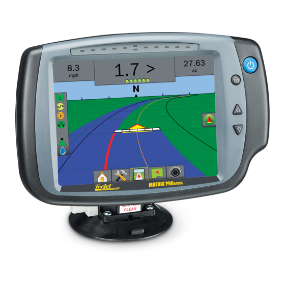
Консоль Matrix Pro 570GS
Система Matrix Pro 570GS создана для многолетнего использования в типичных сельскохозяйственных рабочих условиях. Плотно подогнанный
корпус, в комбинации с резиновыми колпачками на всех разъемах предотвратит неисправности, которые могли бы возникнуть в результате
эксплуатации в пыльной среде. Несмотря на то, что случайное попадание небольшого количества воды на устройство не может ему
повредить, консоль Matrix Pro 570GS не рассчитана на непосредственное нахождение под дождем. Консоль Matrix Pro GS не должна
эксплуатироваться во влажных условиях.
Рисунок 1-1: Консоль Matrix Pro 570GS , вид спереди и сзади
Кнопка питания
Порт USB с резиновой крышкой
Резиновые крышки
соединителей
Соединение антенны GPS
Встроенный кронштейн RAM
(требуется сборка)
Динамик
Утопленные разъемы
Соединение сигнала скорости
Соединение камеры
Соединение источника питания
Встроенная светодиодная панель
Кнопка питания
Порт USB с резиновой крышкой
Стандартный кронштейн RAM
(требуется сборка)
Яркий сенсорный экран

Консоль matrix pro 840gs, Камера realview, Дополнительная информация
Включение питания, Выключение питания, Цикл запуска, Рекомендации по установке антенны
- Изображение
- Текст
2
www.teejet.com
НАЧА
ЛЬ
НЫЙ ЭКР
АН
ОБ
ЗОР
НА
С
ТР
ОЙК
А
ОР
УДИЕ
ПО
ЛНЫЙ ЭКР
АН
GPS
ВВЕ
ДЕНИЕ
НАВИГ
АЦИЯ
МОНИТ
ОР Р
АЗМЕР
А К
АПЕ
ЛЬ
Консоль Matrix Pro 840GS
Система Matrix Pro 840GS создана для многолетнего использования в типичных сельскохозяйственных рабочих условиях. Плотно подогнанный
корпус, в комбинации с резиновыми колпачками на всех разъемах предотвратит неисправности, которые могли бы возникнуть в результате
эксплуатации в пыльной среде. Несмотря на то, что случайное попадание воды на устройство не может ему повредить, консоль Matrix Pro 840GS
не рассчитана на непосредственное нахождение под дождем. Консоль Matrix Pro GS не должна эксплуатироваться во влажных условиях.
Рисунок 1-2: Консоль Matrix Pro 840GS, вид спереди и сзади
Встроенная светодиодная панель
Кнопка питания
Порт USB
с резиновым
колпачком
Стандартный
кронштейн RAM
(требуется сборка)
Яркий сенсорный
экран
Кнопка возврата на основной экран
Кнопка увеличения/
уменьшения
Резиновые крышки
соединителей
Соединение антенны
GPS
Встроенный кронштейн RAM
(требуется сборка)
Динамик
Соединение сигнала скорости
Соединение камеры
Соединение источника питания
Камера RealView®
Камера режима реального видео RealView от TeeJet Technologies позволяет выводить видеоизображение на экран Matrix Pro GS. Камера
может быть направлена вперед для обеспечения навигации в режиме реального видео, или же ее можно навести так, чтобы наблюдать
другие рабочие аспекты вашего оборудования. Камера оснащена гибким кронштейном RAM Mount, встроенным козырьком, и инфракрасной
подсветкой, что позволяет получать четкое видеоизображение даже в темное время суток.
Дополнительная информация
Все изменения сохраняются автоматически.
При смене или установке оборудования на систему Matrix Pro GS
консоль необходимо выключить и включить заново.
Включение питания
Чтобы включить консоль, нажмите КНОПКУ ПИТАНИЯ
на консоли.
После включения Matrix Pro GS начнет процесс запуска.
Выключение питания
Чтобы отключить питание, нажмите и недолго удерживайте
КНОПКУ ПИТАНИЯ
, пока не отобразится окно подтверждения
выключения.
ВНИМАНИЕ! После выключения питания подождите 30 секунд
перед повторным включением.
Цикл запуска
Включение экрана занимает приблизительно 40 секунд. В течение
этого времени отображается серия экранов, светодиоды включаются
и выключаются, яркость изменяется. По окончании цикла пуска
появится начальный экран.
Рекомендации по установке антенны
Антенна GPS должна устанавливаться на кабине как можно ближе
к ее передней части, на металлической поверхности площадью не
менее 10 кв. см.

3
98-05273-RU R4
НАЧА
ЛЬ
НЫЙ ЭКР
АН
ОБ
ЗОР
НА
С
ТР
ОЙК
А
ОР
УДИЕ
ПО
ЛНЫЙ ЭКР
АН
GPS
ВВЕ
ДЕНИЕ
НАВИГ
АЦИЯ
МОНИТ
ОР Р
АЗМЕР
А К
АПЕ
ЛЬ
коНфИгурацИя
На следующей диаграмме отображается стандартная конфигурация Matrix Pro GS. Вследствие большого разнообразия возможных
конфигураций, она должна использоваться только в качестве справочного материала.
Рисунок 1-3: Matrix Pro GS с VSM и несколькими камерами RealView,
автопилотом FieldPilot и автоматическим управлением секциями
штанги BoomPilot
45-05626
Кабель питания, CAN
(в комплекте с
FieldPilot
,
UniPilot
или
BoomPilot
)
10A Fuse
8-кон.
к RS-232
Модуль управления
секциями штанги
BoomPilot
(15 секций)
Пучок проводов
BoomPilot. Номер детали
зависит от регулятора расхода
Пучок проводов экрана
Регулятор расхода
Дистанционный
переключатель
статуса ABSC
(Автоматического
управления
секциями штанги)
Клапаны
45-05381
3.66 м
кабель с
предох-
ранителем
15 А
78-08075
Модуль рулевого
управления (SCM)
45-07703
SCM питание ввод/вывод
45-10103
Пучок
проводов
рулевого
управления (A+B)
78-08072
Регулятор
напряжения
45-07708
Пучок проводов
SCM (Модуля
рулевого
управления)
32-04020
Дополнительно
ножной
переключатель
32-04040
Переключатель
дистанционного
включения/
выключения
91-07011
Перекл-
ючатель
управления
рулем,
комплект
45-08117
Удлинительный кабель CAN 6 м
Гидравлический
распределитель
16-00022
Камера режима
реального видео
Видеокоммутатор
78-08067: 4-канальный
78-08068: 8-канальный
90-04005: 3 м
90-04006: 10 м
Интерфейсный набор для
показаний давления на мониторе размера капли
45-05786: 6 м
45-05787: 9 м
Кабель антенны
78-50187
RXA-30
Антенна GPS
65-05226
Комплект крепления
антенны RXA-30
45-05617: 6 м
45-05618: 18 м
Удлинительный кабель камеры
5-кон.
Matrix Pro 570GS
75-30082
75-30083 c GLONASS
Matrix Pro 840GS
75-30084
75-30090 c GLONASS
Антенна GPS
78-50155
78-50190 c GLONASS
Монтажный комплект RAM
с чашечным присосом
90-02349 (Matrix 570)
90-02700 (Matrix 840)
Matrix
Подруливание/автопилот
BoomPilot
Вспомогательное оборудование

Глава 2. введение, Базовое использование экрана, Клавиши нижней вкладки
Параметры, недоступные при активном задании
- Изображение
- Текст
4
www.teejet.com
НАЧА
ЛЬ
НЫЙ ЭКР
АН
ОБ
ЗОР
НА
С
ТР
ОЙК
А
ОР
УДИЕ
ПО
ЛНЫЙ ЭКР
АН
GPS
ВВЕ
ДЕНИЕ
НАВИГ
АЦИЯ
МОНИТ
ОР Р
АЗМЕР
А К
АПЕ
ЛЬ
ГлаВа 2. ВВеДеНие
Matrix Pro GS может использоваться как в качестве простой системы текущего задания, так и в качестве системы многоцелевого назначения
с расширенными возможностями. Независимо от выбранного режима, основные функции экрана остаются неизменными.
• Нижние и боковые вкладки открывают доступ к различным экранам и подэкранам
• Предупреждения и всплывающие информационные окна сообщают о работе консоли и функциях навигации
• Параметры настройки можно легко установить с помощью раскрывающихся меню или экранной клавиатуры
Чтобы быстро найти функцию настройки, см. таблицу «Схема меню настройки режимов устройства».
БазовоЕ ИСПользоваНИЕ экраНа
Клавиши нижней вкладки
Клавиши нижних вкладок всегда находятся на экране. Эти кнопки
открывают доступ к заданиям, опциям настройки и навигации.
Начальный экран/экран задания
Настройка устройства
Навигация в представлении машины
Навигация в представлении поля
Навигация RealView или
Полноэкранное представление видео с камеры RealView
ПРИМЕЧАНИЕ: Параметры навигации RealView доступны,
только если в системе установлена камера.
Рисунок 2-1: Клавиши нижней вкладки
0,0
км/ч
0,00
га
> 0,0 <
Параметры, недоступные при активном задании
При активном задании некоторые параметры настройки становятся
недоступными. Недоступные параметры указаны в таблице
«Структурная схема меню режимов настройки устройства».
Рисунок 2-2: Примеры недоступных параметров

Нажмите на кнопку для помощи

