В настоящий момент товары недоступны для заказа на samsung.com/ru
В настоящий момент товары недоступны для заказа на samsung.com/ru
Выберите свое местоположение и язык.

-
Программное обеспечение
Где скачать прошивку для телевизора SamsungЧасто задаваемые вопросы о технике Телевизоры Samsung. Узнайте подробнее о ‘Где скачать прошивку для телевизора Samsung’ с помощью службы поддержки Samsung.
-
Каналы
Как удалить ненужные каналы на телевизоре SamsungЧасто задаваемые вопросы о технике Телевизоры Samsung. Узнайте подробнее о ‘Как удалить ненужные каналы на телевизоре Samsung’ с помощью службы поддержки Samsung.
-
Программное обеспечение
Как обновить прошивку на телевизоре Samsung через флешку (по USB)Часто задаваемые вопросы об аудио и видео технике Samsung. Узнайте подробнее о ‘Как обновить прошивку на телевизоре Samsung через флешку (по USB)’ с помощью службы поддержки Samsung.
-
Каналы
Как найти и настроить эфирные и кабельные каналы на телевизоре SamsungЧасто задаваемые вопросы о технике Телевизоры Samsung. Узнайте подробнее о ‘Как найти и настроить эфирные и кабельные каналы на телевизоре Samsung’ с помощью службы поддержки Samsung.
-
Использование
Как сделать сброс настроек на телевизоре SamsungЧасто задаваемые вопросы о технике Телевизоры Samsung. Узнайте подробнее о ‘Как сделать сброс настроек на телевизоре Samsung’ с помощью службы поддержки Samsung.
-
Сеть / Интернет
Как подключить телевизор Samsung к интернету по Wi-FiЧасто задаваемые вопросы о технике Телевизоры Samsung. Узнайте подробнее о ‘Как подключить телевизор Samsung к интернету по Wi-Fi’ с помощью службы поддержки Samsung.
-
Питание
Что делать, если телевизор Samsung не включаетсяЧасто задаваемые вопросы об аудио и видео технике Samsung. Узнайте подробнее о ‘Что делать, если телевизор Samsung не включается’ с помощью службы поддержки Samsung.
-
Использование
Как подключить смартфон или планшет к ТВ Samsung через функцию Screen MirroringЧасто задаваемые вопросы о технике Телевизоры Samsung. Узнайте подробнее о ‘Как подключить смартфон или планшет к ТВ Samsung через функцию Screen Mirroring’ с помощью службы поддержки Samsung.
-
Программное обеспечение
Как обновить прошивку Smart-телевизора Samsung через интернетЧасто задаваемые вопросы об аудио и видео технике Samsung. Узнайте подробнее о ‘Как обновить прошивку Smart-телевизора Samsung через интернет’ с помощью службы поддержки Samsung.
-
Установка / Подключение
Что делать, если нет сигнала при подключении по HDMI на телевизоре SamsungЧасто задаваемые вопросы о технике Телевизоры Samsung. Узнайте подробнее о ‘Что делать, если нет сигнала при подключении по HDMI на телевизоре Samsung’ с помощью службы поддержки Samsung.
-
Использование
Как использовать HDMI ARC в телевизорах Samsung Smart TVЧасто задаваемые вопросы о телевизорах Samsung. Обратитесь в службу поддержки Samsung, чтобы получить дополнительную информацию о том, как использовать HDMI ARC в телевизорах Samsung Smart TV.
-
Использование
Как включить игровой режим на телевизоре Samsung?Часто задаваемые вопросы о технике Телевизоры Samsung. Узнайте подробнее о ‘Как включить игровой режим на телевизоре Samsung?’ с помощью службы поддержки Samsung.
-
Звук
Что делать, если прерывается звук на телевизоре SamsungЧасто задаваемые вопросы о SmartThings. Узнайте подробнее о ‘Что делать, если прерывается звук на телевизоре Samsung’ с помощью службы поддержки Samsung.
-
Использование
Что делать, если не воспроизводятся видео с USB на телевизоре SamsungЧасто задаваемые вопросы об аудио и видео технике Samsung. Узнайте подробнее о ‘Что делать, если не воспроизводятся видео с USB на телевизоре Samsung’ с помощью службы поддержки Samsung.
-
Использование
Как правильно подключить CAM-модуль к телевизоруЧасто задаваемые вопросы о технике Телевизоры Samsung. Узнайте подробнее о ‘Как правильно подключить CAM-модуль к телевизору’ с помощью службы поддержки Samsung.
-
Аксессуары
Как подключить интеллектуальный пульт к телевизору SamsungЧасто задаваемые вопросы о технике Телевизоры Samsung. Узнайте подробнее о ‘Как подключить интерактивный пульт Smart Touch Control к телевизору Samsung’ с помощью службы поддержки Samsung.
-
Изображение
Что делать, если мерцает изображение на телевизоре SamsungЧасто задаваемые вопросы о технике Телевизоры Samsung. Узнайте подробнее о ‘Что делать, если мерцает изображение на телевизоре Samsung’ с помощью службы поддержки Samsung.
-
Сеть / Интернет
Как подключить телевизор Samsung к интернету по кабелю (проводу)Часто задаваемые вопросы о технике Телевизоры Samsung. Узнайте подробнее о ‘Как подключить телевизор Samsung к интернету по кабелю (проводу)’ с помощью службы поддержки Samsung.
-
Изображение
Размытое, нечеткое изображение на экране телевизора SamsungРазмытое изображение на телевизоре Samsung? Пошаговая инструкция от производителя в этой статье.
-
Изображение
Линии, полосы, темные пятна, разводы на экране телевизора SamsungРекомендации, если на экране телевизора Samsung линии, полосы, темные пятна, разводы
-
Питание
Загорается экран на выключенном телевизоре Samsung. Телевизор сам включаетсяЧасто задаваемые вопросы о технике Телевизоры Samsung. Узнайте подробнее о ‘Загорается экран на выключенном телевизоре Samsung. Телевизор сам включается’ с помощью службы поддержки Samsung.
-
Изображение
Что делать, если искажаются цвета на телевизоре SamsungЧасто задаваемые вопросы о технике Телевизоры Samsung. Узнайте подробнее о ‘Что делать, если искажаются цвета на телевизоре Samsung’ с помощью службы поддержки Samsung.
-
Каналы
Что делать, если телевизор Samsung не видит CAM-модульЧасто задаваемые вопросы о Бытовой технике Samsung. Узнайте подробнее о ‘Что делать, если телевизор Samsung не видит CAM-модуль’ с помощью службы поддержки Samsung.
-
TV_Прочее
Что делать, если не работает пульт от телевизора Samsung?Часто задаваемые вопросы о технике Мобильные устройства Samsung. Узнайте подробнее о ‘Что делать, если не работает пульт от телевизора Samsung?’ с помощью службы поддержки Samsung.
-
Использование
Как создать учетную запись (Samsung Account) на телевизоре SamsungЧасто задаваемые вопросы об аудио и видео технике Samsung. Узнайте подробнее о ‘Как создать учетную запись на телевизоре Samsung’ с помощью службы поддержки Samsung.
-
Использование
Как настроить управление голосом через Google Assistant на телевизоре SamsungЧасто задаваемые вопросы о технике Телевизоры Samsung. Узнайте подробнее о ‘Как показывать часы и уведомления на экране блокировки Samsung Galaxy’ с помощью службы поддержки Samsung.
-
Установка / Подключение
Как подключить внешнее устройство через тюльпаны (RCA) к телевизору SamsungЧасто задаваемые вопросы о технике Мобильные устройства Samsung. Узнайте подробнее о ‘Как подключить внешнее устройство через тюльпаны (RCA) к телевизору Samsung’ с помощью службы поддержки Samsung.
-
Установка / Подключение
Как подключить ТВ-приставку (ресивер) кабелем HDMI к телевизору SamsungЧасто задаваемые вопросы о технике Мобильные устройства Samsung. Узнайте подробнее о ‘Как подключить приставку (ресивер) кабелем HDMI к телевизору Samsung’ с помощью службы поддержки Samsung.
-
Сеть / Интернет
Как посмотреть MAC-адрес на телевизоре SamsungЧасто задаваемые вопросы о технике Телевизоры Samsung. Узнайте подробнее о ‘Как посмотреть MAC-адрес на телевизоре Samsung’ с помощью службы поддержки Samsung.
-
Звук
Как настроить или отключить звуковые сигналы на телевизоре SamsungЧасто задаваемые вопросы о технике Телевизоры Samsung. Узнайте подробнее о ‘Как настроить или отключить звуковые сигналы на телевизоре Samsung’ с помощью службы поддержки Samsung.
-
Использование
Как настроить дату и время на телевизоре SamsungЧасто задаваемые вопросы о технике Телевизоры Samsung. Узнайте подробнее о ‘Как настроить дату и время на телевизоре Samsung’ с помощью службы поддержки Samsung.
-
Использование
Как подключить беспроводной сабвуфер к саундбаруЧасто задаваемые вопросы о технике Мобильные устройства Samsung. Узнайте подробнее о ‘Как подключить беспроводной сабвуфер к саундбару’ с помощью службы поддержки Samsung.
-
Каналы
Как записывать ТВ программы на телевизоре SamsungИщете инструкцию по записи каналов на телевизоре Samsung? Подробная информация от производителя в этой статье.
-
TV_Прочее
Что делать, если забыл PIN-код от телевизора SamsungЧасто задаваемые вопросы о технике Телевизоры Samsung. Узнайте подробнее о ‘Что делать, если забыл пин-код от телевизора Samsung’ с помощью службы поддержки Samsung.
-
Изображение
Что делать, если на телевизоре Samsung появляется реклама и изменяются настройкиЧасто задаваемые вопросы о технике Телевизоры Samsung. Узнайте подробнее о ‘Что делать, если на телевизоре Samsung появляется реклама и изменяются настройки’ с помощью службы поддержки Samsung.
-
Использование
Как включить субтитры на цифровых каналах на телевизоре SamsungЧасто задаваемые вопросы об аудио и видео технике Samsung. Узнайте подробнее о ‘Как включить субтитры на цифровых каналах на телевизоре Samsung’ с помощью службы поддержки Samsung.
-
Приложения Samsung
Что делать, если не хватает памяти при установке приложения на телевизоре SamsungЧасто задаваемые вопросы об аудио и видео технике Samsung. Узнайте подробнее о ‘Как установить приложение для телевизора Samsung на USB-накопитель’ с помощью службы поддержки Samsung.
-
Использование
Как сделать изображение с проектора Samsung The Freestyle четчеЧасто задаваемые вопросы о проекторах Samsung. Узнайте подробнее о ‘Как сделать изображение с проектора Samsung The Freestyle четче’ с помощью службы поддержки Samsung.
-
Использование
Как использовать внешний аккумулятор для проектора Samsung The FreestyleЧасто задаваемые вопросы о проекторах Samsung. Узнайте подробнее о ‘Как использовать внешний аккумулятор для проектора Samsung The Freestyle’ с помощью службы поддержки Samsung.
-
Использование
Как дублировать изображение с телевизора на проектор SamsungЧасто задаваемые вопросы об аудио и видео технике Samsung. Узнайте подробнее о ‘Как дублировать изображение с телевизора на проектор Samsung’ с помощью службы поддержки Samsung.
-
Использование
Как очистить экран телевизора SamsungЧасто задаваемые вопросы об аудио и видео технике Samsung. Узнайте подробнее о ‘Как очистить экран телевизора Samsung’ с помощью службы поддержки Samsung.
-
Использование
Как дублировать экран iOS-устройства на телевизор Samsung по AirPlay 2Часто задаваемые вопросы о телевизорах Samsung. Узнайте подробнее о «Как дублировать экран iOS-устройства на телевизор Samsung по AirPlay 2» с помощью службы поддержки Samsung.
-
Установка / Подключение
Как снять подставку на телевизоре Samsung K-серии (2016)Часто задаваемые вопросы о телевизорах Samsung. Узнайте подробнее о ‘Как снять подставку на телевизоре Samsung K-серии (2016)’ с помощью службы поддержки Samsung.
-
Использование
Как добавить телевизор в приложение SmartThingsЧасто задаваемые вопросы о SmartThings. Узнайте подробнее о ‘Как добавить телевизор в приложение SmartThings’ с помощью службы поддержки Samsung.
-
Установка / Подключение
Как подключить Samsung Galaxy к телевизору Samsung через приложение SmartThingsЧасто задаваемые вопросы о SmartThings. Узнайте подробнее о ‘Как подключить Samsung Galaxy к телевизору Samsung через приложение SmartThings’ с помощью службы поддержки Samsung.
-
TV_Прочее
Что делать, если слышен писк от телевизора SamsungЧасто задаваемые вопросы о технике Телевизоры Samsung. Узнайте подробнее о ‘Слышен шум, свист, гудение, гул, писк из телевизора Samsung’ с помощью службы поддержки Samsung.
ДОПОЛНИТЕЛЬНАЯ ИНФОРМАЦИЯ
Информация о гарантии
Узнайте, что входит в гарантийные обязательства


Индивидуальная поддержка
Получите помощь от официальных центров поддержки


Новости и уведомления
Обьявления о важных продуктах и услугах


Руководства Samsung CK3385ZR4X Размер файлов: 3913 KB, Язык: English, Формат: pdf, Платформа: Windows/Linux, Дата: 2015-03-21
На данной странице вы можете скачать руководства Samsung CK3385ZR4X. Мы предлагаем вам ознакомиться с руководством пользователя, инструкцией по сервисному обслуживанию и ремонту.
Также здесь вы найдете список заказных номеров на комплектующие Samsung CK3385ZR4X.
Все файлы предоставляются исключительно в ознакомительных целях. И не являютя руководством по ремонту, а направлены лишь на то чтобы помочь вам более детально ознакомиться с принципом построения устройства.
Содержимое представленных здесь руководств требуют от вас знания технического английского языка.
Если вы собираетесь скачать руководство по сервисному обслуживанию Samsung CK3385ZR4X, иными словами сервис мануал, вы дожны обладать хотя бы минимальными познаниями в области электроники и пониманием базовых принципов работы электромеханических устройств.
Для просмотра руководств вам понадобится Adobe Acrobat Reader версии 9 и выше либо другая программа для просмотра pdf файлов.
В связи с популярностью информации представленной на сайте и ее бесплатного предоставления конечному пользователю, убедительная просьба использовать специальные программные продукты для многопотокового скачивания файлов.
Руководства для Samsung CK3385ZR4X
- Руководство пользователя (User manual)
- Руководство по сервисному обслуживанию (Service manual)
- Руководство по ремонту (Repair manual)
- Перечень комплектующих (PartList)
![]()
COLOR TELEVISION RECEIVER
Chassis : SCT13B
Model: CK3338ZR4X/BWT
CK5038ZR4X/BWT
CK5338ZR4X/BWT
|
COLOR TELEVISION RECEIVER |
CONTENTS |
||||
|
1. |
Precautions |
||||
|
2. |
Specifications and IC Data |
||||
|
3. |
Disassembly and Reassembly |
||||
|
4. |
Alignment and Adjustment |
||||
|
5. |
Troubleshooting |
||||
|
6. |
Exploded View and Parts List |
||||
|
7. |
Electric Parts List |
||||
|
8. |
Block Diagram |
||||
|
9. |
PCB Layout Diagram |
||||
|
10. |
Wiring Diagram |
||||
|
11. |
Schematic Diagrams |
||||

ELECTRONICS
©Samsung Electronics Co., Ltd. MAY.1998 Printed in Korea
3SCT13B-38K301

Precautions
1. Precautions
Follow these safety, servicing and ESD precautions to prevent damage and protect against potential hazards such as electrical shock and X-rays.
1-1 Safety Precautions
1.Be sure that all of the built-in protective devices are replaced. Restore any missing protective shields.
2.When reinstalling the chassis and its assemblies, be sure to restore all protective devices, including: nonmetallic control knobs and compartment covers.
3.Make sure that there are no cabinet openings through which people—particularly children—might insert fingers and contact dangerous voltages. Such openings include the spacing between the picture tube and the cabinet mask, excessively wide cabinet ventilation slots, and improperly fitted back covers.
If the measured resistance is less than 1.0 megohm or greater than 5.2 megohms, an abnormality exists that must be corrected before the unit is returned to the customer.
4.Leakage Current Hot Check (Figure 1-1): Warning: Do not use an isolation transformer during this test. Use a leakagecurrent tester or a metering system that complies with American National Standards Institute (ANIS C101.1, Leakage Current for Appliances), and Underwriters Laboratories (UL Publication UL1410, 59.7).
5.With the unit completely reassembled, plug the AC line cord directly into the power outlet. With the unit’s AC switch first in the ON position and then OFF, measure the current between a known earth ground (metal water pipe, conduit, etc.) and all exposed metal parts, including: antennas, handle brackets, metal cabinets, screwheads and control shafts. The current measured should not exceed 0.5 milliamp. Reverse the powerplug prongs in the AC outlet and repeat the test.
|
(READING SHOULD |
|||||||||||
|
LEAKAGE |
NOT BE ABOVE |
||||||||||
|
DEVICE |
CURRENT |
0.5mA) |
|||||||||
|
UNDER |
TESTER |
||||||||||
|
TEST |
|||||||||||
|
TEST ALL |
|||||||||||
|
EXPOSED METAL |
|||||||||||
|
SURFACES |
|||||||||||
|
2-WIRE CORD |
|||||||||||
|
ALSO TEST WITH |
|||||||||||
|
PLUG REVERSED |
|||||||||||
|
(USING AC ADAPTER |
EARTH |
||||||||||
|
PLUG AS REQUIRED) |
GROUND |
Fig. 1-1 AC Leakage Test
6.Antenna Cold Check:
With the unit’s AC plug disconnected from the AC source, connect an electrical jumper across the two AC prongs. Connect one lead of the ohmmeter to an AC prong. Connect the other lead to the coaxial connector.
7.X-ray Limits:
The picture tube is especially designed to prohibit X-ray emissions. To ensure continued X-ray protection, replace the picture tube only with one that is the same type as the original. Carefully reinstall the picture tube shields and mounting hardware; these also provide X-ray protection.
8.High Voltage Limits:
High voltage must be measured each time servicing is done on the B+, horizontal deflection or high voltage circuits. Correct operation of the X-ray protection circuits must be reconfirmed whenever they are serviced. (X-ray protection circuits also may be called “horizontal disable” or “hold-down”.)
Heed the high voltage limits. These include the X–ray Protection Specifications Label, and the Product Safety and X-ray Warning Note on the service data schematic.

Precautions
1-1 Safety Precautions (Continued)
9.High voltage is maintained within specified limits by close-tolerance, safety-related components and adjustments. If the high voltage exceeds the specified limits, check each of the special components.
10.Design Alteration Warning:
Never alter or add to the mechanical or electrical design of this unit. Example: Do not add auxiliary audio or video connectors. Such alterations might create a safety hazard. Also, any design changes or additions will void the manufacturer’s warranty.
11.Hot Chassis Warning:
Some TV receiver chassis are electrically connected directly to one conductor of the AC power cord. If an isolation transformer is not used, these units may be safely serviced only if the AC power plug is inserted so that the chassis is connected to the ground side of the AC source.
To confirm that the AC power plug is inserted correctly, do the following: Using an AC voltmeter, measure the voltage between the chassis and a known earth ground. If the reading is greater than 1.0V, remove the AC power plug, reverse its polarity and reinsert. Re-measure the voltage between the chassis and ground.
12.Some TV chassis are designed to operate with 85 volts AC between chassis and ground, regardless of the AC plug polarity. These units can be safely serviced only if an isolation transformer inserted between the receiver and the power source.
13.Some TV chassis have a secondary ground system in addition to the main chassis ground. This secondary ground system is not
isolated from the AC power line. The two ground systems are electrically separated by insulating material that must not be defeated or altered.
14.Components, parts and wiring that appear to have overheated or that are otherwise damaged should be replaced with parts that meet the original specifications. Always determine the cause of damage or overheating, and correct any potential hazards.
15.Observe the original lead dress, especially near the following areas: Antenna wiring, sharp edges, and especially the AC and high voltage power supplies. Always inspect for pinched, out-of-place, or frayed wiring. Do not change the spacing between components and the printed circuit board. Check the AC power cord for damage. Make sure that leads and components do not touch thermally hot parts.
16.Picture Tube Implosion Warning:
The picture tube in this receiver employs “integral implosion” protection. To ensure continued implosion protection, make sure that the replacement picture tube is the same as the original.
17.Do not remove, install or handle the picture tube without first putting on shatterproof goggles equipped with side shields. Never handle the picture tube by its neck. Some “in-line” picture tubes are equipped with a permanently attached deflection yoke; do not try to remove such “permanently attached” yokes from the picture tube.
18.Product Safety Notice:
Some electrical and mechanical parts have special safety-related characteristics which might not be obvious from visual inspection. These safety features and the protection they give might be lost if the replacement component differs from the original—even if the replacement is rated for higher voltage, wattage, etc.
Components that are critical for safety are indicated in the circuit diagram by shading,
(  ) or ( ! ).
Use replacement components that have the same ratings, especially for flame resistance and dielectric strength specifications.
A replacement part that does not have the same safety characteristics as the original might create shock, fire or other hazards.

Precautions
1-2 Servicing Precautions
Warning1: First read the “Safety Precautions” section of this manual. If some unforeseen circumstance creates a conflict between the servicing and safety precautions, always follow the safety precautions.
Warning2: An electrolytic capacitor installed with the wrong polarity might explode.
1.Servicing precautions are printed on the cabinet. Follow them.
2.Always unplug the unit’s AC power cord from the AC power source before attempting to: (a) Remove or reinstall any component or assembly, (b) Disconnect an electrical plug or connector, (c) Connect a test component in parallel with an electrolytic capacitor.
3.Some components are raised above the printed circuit board for safety. An insulation tube or tape is sometimes used. The internal wiring is sometimes clamped to prevent contact with thermally hot components. Reinstall all such elements to their original position.
4.After servicing, always check that the screws, components and wiring have been correctly reinstalled. Make sure that the portion around the serviced part has not been damaged.
5.Check the insulation between the blades of the AC plug and accessible conductive parts (examples: metal panels, input terminals and earphone jacks).
6.Insulation Checking Procedure: Disconnect the power cord from the AC source and turn the power switch ON. Connect an insulation resistance meter (500V) to the blades of the AC plug.
The insulation resistance between each blade of the AC plug and accessible conductive parts (see above) should be greater than 1 megohm.
7.Never defeat any of the B+ voltage interlocks. Do not apply AC power to the unit (or any of its assemblies) unless all solid-state heat sinks are correctly installed.
8.Always connect a test instrument’s ground lead to the instrument chassis ground before connecting the positive lead; always remove the instrument’s ground lead last.

Precautions
1-3 Precautions for Electrostatically Sensitive Devices (ESDs)
1.Some semiconductor (“solid state”) devices are easily damaged by static electricity. Such components are called Electrostatically Sensitive Devices (ESDs); examples include integrated circuits and some field-effect transistors. The following techniques will reduce the occurrence of component damage caused by static electricity.
2.Immediately before handling any semicon ductor components or assemblies, drain the electrostatic charge from your body by touching a known earth ground. Alternatively, wear a discharging wrist-strap device. (Be sure to remove it prior to applying power— this is an electric shock precaution.)
3.After removing an ESD-equipped assembly, place it on a conductive surface such as aluminum foil to prevent accumulation of electrostatic charge.
4.Do not use freon-propelled chemicals. These can generate electrical charges that damage ESDs.
5.Use only a grounded-tip soldering iron when soldering or unsoldering ESDs.
6.Use only an anti-static solder removal device. Many solder removal devices are not rated as “anti-static”; these can accumulate sufficient electrical charge to damage ESDs.
7.Do not remove a replacement ESD from its protective package until you are ready to install it. Most replacement ESDs are packaged with leads that are electrically shorted together by conductive foam, aluminum foil or other conductive materials.
8.Immediately before removing the protective material from the leads of a replacement ESD, touch the protective material to the chassis or circuit assembly into which the device will be installed.
9.Minimize body motions when handling unpackaged replacement ESDs. Motions such as brushing clothes together, or lifting a foot from a carpeted floor can generate enough static electricity to damage an ESD.
Specifications and IC Data
2. Specifications and IC Data
2-1 Specifications
|
Television System: |
MODEL |
SYSTEM |
||||||||||||||
|
CI |
PAL-I (UHF) |
|||||||||||||||
|
CII |
PAL-I (VHF/UHF) |
|||||||||||||||
|
CX |
PAL-B/G, SECAM-B/G |
|||||||||||||||
|
CK |
PAL-B/G, D/K, SECAM-B/G, D/K |
|||||||||||||||
|
CW |
PAL-B/G, D/K, SECAM-B/G, D/K, NT 4.43 |
|||||||||||||||
|
CS |
PAL-B/G, D/K, SECAM-B/G, D/K, NT4.43, NT3.58 |
|||||||||||||||
|
Channels: |
||||||||||||||||
|
System |
PAL/SECAMPAL, |
SECAM-K1, NTSC — M |
||||||||||||||
|
Band |
B/G,I |
SECAM- D/K |
PAL-D |
|||||||||||||
|
VHF |
2 — 12 |
1 — 13 |
2 — 9 |
2 — 13 |
||||||||||||
|
UHF |
21 — 69 |
21 — 69 |
13 — 57 |
14-69 |
||||||||||||
|
Intermediate Frequencies (MHz) : |
SYSTEM |
PAL/ |
PAL/SECAM-D/K, |
PAL — I |
NTSC — M |
|||||||||||
|
IF Carrier Frequency |
SECAM- B/G |
SECAM-K1 |
||||||||||||||
|
Picture IF Carrier |
38.90 |
38.90 |
38.90 |
38.90 |
||||||||||||
|
Sound IF Carrier |
33.40 |
32.40 |
32.90 |
34.40 |
||||||||||||
|
Color Sub Carrier |
34.47 |
34.47 |
34.47 |
35.32 |
||||||||||||
|
Picture Tube: |
||||||||||||||||
|
14 Inch |
A34KQV42X |
Quick start, in-line-gun, |
||||||||||||||
|
20 Inch |
A48KRD82X |
Black stripe, 90 degree deflection |
||||||||||||||
|
21 Inch |
A51KQJ63X |
|||||||||||||||
|
Power Requirements: |
||||||||||||||||
|
AC 100~260V, 50/60Hz |
||||||||||||||||
|
Antenna Input Impedance: |
VHF, UHF : Telescopic dipole antenna (75 ohm unbalanced type ) |
|||||||||||||||
|
Speaker Impedance |
8 ohm, 5W+5W (Dual Type) |
|||||||||||||||
|
16 ohm, 3W (Monitor Type) |

Specifications and IC Data
2-2 IC Line Up
|
Table 2-1 IC Line-Up |
|||||
|
Loc. No |
Specification |
Description |
Remark |
||
|
HC101 |
PAP102 |
IF PRE-AMP |
|||
|
IC201 |
TDA8374A N3 |
PAL-B/G, SECAM-B/G, NTSC |
Philips |
||
|
IC202 |
TDA4665 |
1H DELAY |
SECAM |
||
|
IC203 |
TDA8395P |
SECAM DECODER |
MODULE |
||
|
IC301 |
TDA8356 |
VERTICAL OUTPUT |
|||
|
IC501 |
TDA6107Q |
RGB DRIVE AMP |
|||
|
IC601 |
TDA7056B |
SOUND-AMP (3.5W) |
Monitor Type |
||
|
IC602 |
TDA7057AQ |
SOUND-AMP (5W+5W) |
Dual Type |
||
|
IC801 |
KA3S0680R |
POWER IC (STR) |
|||
|
IC802 |
KA7630 |
CUSTOM REGULATOR (5V, 8V) |
|||
|
SZM193EA |
W/O TTX, English/French/Arabian |
||||
|
SZM193EV |
W/O TTX, English/Vietnames/Indonesian/Maly/Thai |
||||
|
SZM193EC |
W/O TTX, English/Chinese |
||||
|
SZM191EC |
W/O TTX, English/Chinese |
Zilog |
|||
|
(Non TTX) |
|||||
|
SZM193EE |
W/O TTX, English/German/French/Dutch/Italian/Spanish, |
||||
|
Swedish/Romanian/Hungarian/Croatian/Polish/Russian, |
|||||
|
Czech/Bulgarian/Yugo/Greek |
|||||
|
IC901 |
|||||
|
SZM191ER |
W/O TTX, English/Russian (Only for Oceania model) |
||||
|
SPM197EE |
TTX, West : English/German/French/Dutch/Italian/Spanish/Swedish |
||||
|
East : English/Czech/Croatian/Romanian/Hungarian/Polish |
|||||
|
SPM197ER |
TTX, English/Russian/Bulgarian |
||||
|
SPM197EP |
TTX, English/Iranian |
Philips |
|||
|
(TTX) |
|||||
|
SPM197EA |
TTX, English/French/Arabian |
||||
|
SPM197EG |
TTX, English/Greek/Yugo |
||||
|
IC902 |
24C04 |
EEPROM |
|||
|
IC903 |
KiA7042P |
RESET IC ,W/O TTX Model |
Zilog |
||
|
KiA7442P |
TTX Model |
Philips |
|||
|
IC401 |
KA7812 |
REGULATOR (12V) |
|||
|
PC801 |
LTV817B |
PHOTO COUPLER |
NEC |
Specifications and IC Data
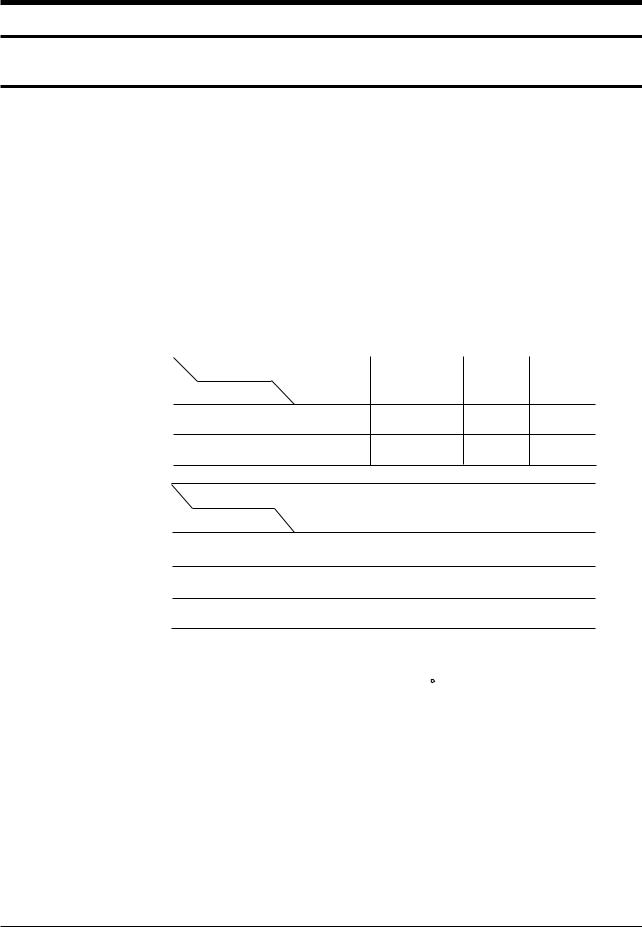
2-3 Semiconductor Base Diagrams
ELECTROLYTIC-
CONDENSER
TRANSISTOR
2SD1651
2SD1650
KSD5072
KSD5071
KSD1711
B
C E
TDA4665(Pin 16)
TDA837X(Pin 56)
Z8933112PSC(Pin 42)
X24CO4P(Pin 
TDA8395(Pin 16)
TDA4665(Pin 16)
|
SAW-FILTER |
|||||
|
TRANSISTOR |
IC |
||||
|
UPC574J |
K6259K |
|
|
KSA815-Y |
or |
|
|
KA33V |
||
|
KSA539-Y |
||
E B C
|
IC |
TRANSISTOR |
TRANSISTOR |
|
TDA8133 |
||
|
TDA8356 |
KSR1012 |
|
|
TDA6101Q |
||
|
KSR1010 |
||
|
KA7812 |
||
|
KA7809 |
KSR2010 |
|
|
KA78R05 |
Fig. 2-1 Semiconductor Base Diagrams

MEMO
![]()
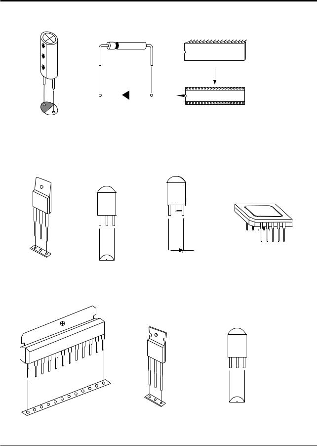
Disassembly and reassembly
3. Disassembly and Reassembly
3-1 Back Cover Removal
1. After removing the 9 screws, pull the cabinet backwards.

Disassembly and reassembly
3-2 Speaker Removal
1. Loosen the 4 screws and remove the holder — speakers.

Disassembly and reassembly
3-3 CRT Removal
1.Spread a soft mat on the floor. Place the TV set face down.
2.Remove the 4 screws mounting the CRT to the front cabinet.
3.Lift the CRT.

MEMO

Alignment and Adjustments
4. Alignment and Adjustments
4-1 Preadjustment
4-1-1 Factory Mode
1.Do not attempt these adjustments in the Video Mode.
2.The Factory Mode adjustments are necessary when either the EEPROM (IC902) or the CRT is replaced.
3.Do not tamper with the “Adjustment” screen of the Factory Mode menu. This screen is intended only for factory use.
4-1-3 When CRT Is Replaced
1.Make the following adjustments AFTER setting up after setting up purity and convergence :
White Balance Sub-Brightness Vertical Center Vertical Size Horizontal Size
Fail Safe (This adjustment must be the last step).
4-1-2 When EEPROM (IC902) Is Replaced
1.When IC902 is replaced all adjustment data revert to initial values. It is necessary to re-program this data.
2.After IC902 is replaced, warm up the TV for 10 seconds.
2.If the EEPROM or CRT is replaced, set SC and PVA to 10 and 45 (Factory mode).
SC : 14, 16 Inch : 0 20, 21 Inch : 10
4-2 Factory/Service Mode
4-2-1 Procedure for the “Adjustment” Mode
1.This mode uses the standard remote control. The Service Mode is activated by entering the following remote-control sequence :
(1)SLEEP→FACTORY.
(2)STAND-BY→P.STD→HELP→SLEEP
→POWER ON.
2.The “SERVICE (FACTORY)” message will be displayed. The Service Mode has four components: Adjustment, Test Pattern, Option Bytes and Reset.
3.Access the Adjustment Mode by pressing the “VOLUME” keys ( Up or Down).
The adjustment parameters are listed in the accompanying table, and selected by pressing the CHANNEL keys (▲ ,▼).
4. Selection sequences for the PAL system:
DOWN or UP key: AGC>VCO>SBT>SCT>SCR>SC>RG> GG>BG>CDL>BLU>PSL>PVS>PVA>PHS
5. Selection sequences for the NTSC system:
DOWN or UP key: AGC>VCO>SBT>SCT>SCR>SC>RG> GG>BG>CDL>BLU>NSL>NVS>NVA>NHS
6.The VOLUME keys increase or decrease the adjustment values, (stored in the
non-volatile memory when Adjustment Mode is cancelled).
7.Cancel the Adjustment Mode by re-pressing the “FACTORY” or Power OFF.

Alignment and Adjustments
4-2-2 Main Adjustment Parameter
Table 4-1 Main Adjustment Parameter (Zilog, Phlips μ-com)
|
FUNCTION |
OSD ABBREVIATION |
RANGE |
INITIAL DATA |
REMARKS |
|
|
AUTO GAIN CONTROL |
AGC |
0 ~ 63 STEP |
32 |
||
|
SUB BRIGHT |
SBT |
0 ~ 23 STEP |
7 |
||
|
SUB CONTRAST |
SCT |
0 ~ 23 STEP |
7 |
||
|
SUB COLOR |
SCR |
0 ~ 23 STEP |
13 |
||
|
RED DRIVE GAIN |
RG |
0 ~ 63 STEP |
32 |
||
|
GREEN DRIVE GAIN |
GG |
0 ~ 63 STEP |
32 |
||
|
BLUE DRIVE GAIN |
BG |
0 ~ 63 STEP |
32 |
||
|
PAL VERTICAL SLOPE |
PSL |
0 ~ 63 STEP |
20 |
||
|
PAL VERTICAL SHIFT |
PVS |
0 ~ 63 STEP |
32 |
TDA8374 |
|
|
PAL VERTICAL AMPLITUDE |
PVA |
0 ~ 63 STEP |
45 |
||
|
PAL HORIZONTAL SHIFT |
PHS |
0 ~ 63 STEP |
32 |
||
|
NTSC VERTICAL SLOPE |
NSL |
0 ~ 63 STEP |
20 |
||
|
NTSC VERTICAL SHIFT |
NVS |
0 ~ 63 STEP |
32 |
||
|
NTSC VERTICAL AMPLITUDE |
NVA |
0 ~ 63 STEP |
45 |
||
|
NTSC HORIZONTAL SHIFT |
NHS |
0 ~ 63 STEP |
32 |
||
|
VOLTAGE CONTROL OSCILLATOR |
VCO |
0 ~ 128 STEP |
64 |
||
|
S-CORRECTION |
SC |
0 ~ 63 STEP |
32 |
||
|
TTX SUB-CONTRAST |
TSS |
0 ~ 63 STEP |
16 |
||
|
CATHODE DRIVE LEVEL |
CDL |
0 ~ 7 STEP |
3 |
TDA8842 |
|
|
BLUE STRETCH MODE |
BLU |
0 ~ 3 STEP |
2 |
||
NOTE : PVS,PVA, PHS, NVS, NVA,NHS parameters must be aligned using both the 50Hz and 60Hz vertical-field rates.

Alignment and Adjustments
4-2-3 Test Pattern (Aging Mode)
1.This mode can be used during servicing, or for confirming that the convergence and purity adjustments are correct.
2.Access the Test Pattern parameters by pressing a CHANNEL keys (▲ ,▼) while the Service Mode is on. The cursor will move to the test pattern. Press the VOLUME keys. On-screen display:
|
°·RED |
||||||||
|
°·GREEN |
||||||||
|
NON -TTX MICOM ONLY |
||||||||
|
°·BLUE |
||||||||
|
°·AGING |
TTX MICOM |
|||||||
3.AGING Mode (Reference Only)
This pattern is used for pre-heating the CRT during manufactur- ing—it is accessed in the factory by twice pressing the “SLEEP → FACTORY→FACTORY “ key, then white pattern will be displayed.
Even if the TV power is cut off, the Aging Mode is not cancelled, The aging mode is cancelled by repressing the “FACTORY” key or pressing the local “CH UP/DOWN” key.
The patterns are displayed at 5 sec intervals : NON-TTX Micom only.
4-2-4 Option Bytes
In the Service Mode, various can be selected via the Option Bytes (8 bits each). Example:
|
SYSTEM OSD DISPLAY |
BIT 6 |
BIT 5 |
BIT 4 |
BIT 3 |
BIT 2 |
BIT 1 |
BIT 0 |
|||
|
BYTE 0 : 8 |
— |
L (BIT : 0) |
H (BIT : |
L (BIT : 0) |
L (BIT : 0) |
L (BIT : 0) |
||||
|
BYTE 1 : 0 |
— |
L (BIT :0) |
L (BIT : 0) |
L (BIT : 0) |
L (BIT : 0) |
L (BIT : 0) |
L (BIT : 0) |
L (BIT : 0) |
||
|
TDA8374, CK SYSTEM, RCA JACK SYSTEM OSD DISPLAY |
||||||||||
|
BYTE 0 : 11 |
L (BIT : 1) |
H (BIT : 0) |
L (BIT : 0) |
H (BIT : 0) |
L (BIT : 1) |
|||||
 Loading…