Установка симкарты
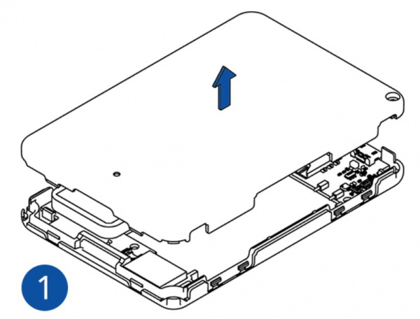
1. Откройте корпус устройства.
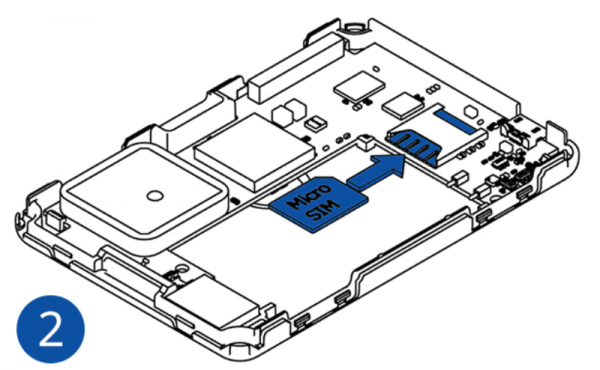
2. Установите сим-карту
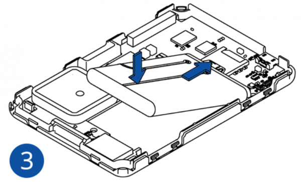
3. Установите аккумулятор
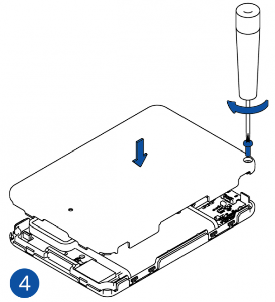
4. Закройте крышку корпуса и зафиксируйте корпус винтом из комплекта
Подключение трекера к ПК
2) Нажмите и удерживайте кнопку питания в течение 7 секунд.
3) Подключите GH5200 к компьютеру, используя Bluetooth соединение или кабель microUSB
Нажмите и удерживайте кнопку питания в течение 7 секунд.
4) Скачайте Teltonika.Configurator для вашей версии прошивки.
Конфигуратор предназначен для ОС Windows.
Обратите внимание, для корректной работы конфигуратора требуется установить MS .NET Framework .
5) Запустите конфигуратор. На первой странице будет доступен выбор языка интерфейса конфигуратора:

6) Конфигуратор определит устройство.
7) После выбора устройства загрузится текущая конфигурация трекера.
- Manuals
- Brands
- Teltonika Manuals
- GPS
- GH5200
- User manual
-
Contents
-
Table of Contents
-
Bookmarks
Quick Links
Related Manuals for Teltonika GH5200
Summary of Contents for Teltonika GH5200
-
Page 1
GH5200 User Manual V1.0… -
Page 2: Table Of Contents
ASIC CHARACTERISTICS ………………….12 ECHNICAL FEATURES …………..12 ECHNICAL NFORMATION ABOUT INTERNAL BATTERY ………………..13 LECTRICAL CHARACTERISTICS CONNECTION ……………………14 GH5200 : ……. 14 OW TO INSERT CARD AND CONNECT THE BATTERY INTO DEVICE GH5200 ………………..15 NSTALLING DRIVERS OPERATIONAL BASICS ………………….. 17 …………………..
-
Page 3
5.12 ……………………. 39 LUETOOTH 5.12.1 General functionality ………………..39 5.12.2 How to connect Bluetooth Hands Free adapter to GH5200 device ……40 5.12.2.1 Bluetooth settings configuration ………………40 5.12.2.2 Connecting Bluetooth Hands Free adapter …………..42 5.12.3 Logging the GH5200 device using your mobile phone ……….42 5.12.4… -
Page 4
7.2.5 SIM APN Name (ID=2001) ………………66 7.2.6 SIM APN Username (ID=2002) ………………. 66 7.2.7 SIM APN Password (ID=2003) ………………66 7.2.8 Domain (ID=2004) …………………. 66 7.2.9 Target Server Port (ID=2005) ………………66 7.2.10 Protocol (ID=2006) ………………..67 7.2.11 Backup Server Domain (ID=2007) …………….67 7.2.12 Backup Server Port (ID=2008) ………………. -
Page 5
7.5.6.6 Send Period (ID=10255) …………………. 77 ………………….77 EATURES ARAMETERS 7.6.1 Alarm ……………………. 77 7.6.1.1 Scenario Settings (ID=11710)………………..77 7.6.1.2 Send SMS To (ID=7245) …………………. 77 7.6.1.3 SMS Text (ID=8245) ………………….77 7.6.1.4 Call Settings (ID=11711) ………………… 78 7.6.1.5 Call to (ID=11712) ………………….. 78 7.6.2 Overspeeding scenario parameters ……………. -
Page 6
7.12.1.1 BT Radio (ID=800) ………………….93 7.12.1.2 Local name (ID 801) ………………….93 7.12.1.3 Local PIN (ID=802) ………………….94 7.12.1.4 Security mode (ID=803) ………………..94 7.12.1.5 External MAC (ID=804) ………………… 94 7.12.1.6 External name (ID=805) ………………..95 7.12.1.7 External PIN (ID=806) ………………….. 95 7.12.1.8 Connection mode (ID=807) ……………….. -
Page 7: Introduction
1 INTRODUCTION Attention Operate the device in suitable conditions Do not use the device where mobile connectivity is forbidden. Road safety first Comply with local traffic laws, always hold your hands on a steering wheel when using a device. Your safety is of utmost importance when you drive. Interference All wireless devices are sensitive to electromagnetic interference, as a result wireless devices affect the performance of each other.
-
Page 8: Brief Description
UAB Teltonika manager in such case. Brief description GH5200 is a handheld tracking device with built-in functions and characteristics of a mobile phone. This device is intended for the surveillance and protection of people, cargo and valuables.
-
Page 9
▪ GNSS – Global Navigation Satellite System: a system with global coverage that uses satellites to provide autonomous geo-spatial positioning. ▪ GPS – Global Positioning System: a worldwide satellite navigational system formed by 24 satellites orbiting the earth and their corresponding receivers on the earth. ▪… -
Page 10
connection and exchange streams of data. TCP guarantees delivery of data and also guarantees that packets will be delivered in the same order in which they were sent. ▪ TMO — Timeout ▪ UDP – User Datagram Protocol – a connectionless protocol that, like TCP, runs on top of IP networks. -
Page 11: Basic Description
Package contents The GH5200 device is supplied to the customer in a cardboard box containing all the equipment that is necessary for operation. The package contains: ▪ GH5200 device;…
-
Page 12: Technical Features
Table 1. Li –ion rechargeable battery, 3.7 V, 1050 mAh Internal back-up Charging Battery voltage V Nominal capacity (mAh) Power (Wh) battery temperature °C Li-ion rechargeable 3.70 1050 3.885 0 – 45 battery Energy consumption has been tested by running GH5200 on battery (4.2 V).
-
Page 13: Electrical Characteristics
Bring damaged or worn-out batteries to your local recycling center or dispose them into a battery recycle bin commonly found in supermarkets. Warranty: batteries are covered by 6 months warranty support. Electrical characteristics Table 2. GH5200 electrical characteristics Value Characteristic description Supply Voltage: Min.
-
Page 14: Connection
3 CONNECTION How to insert SIM card and connect the battery into GH5200 device: Remove GH5200 cover. Insert Micro SIM card as shown. Battery has to be disconnected at this point. Insert the battery. Reatach the cover and tighten the srew Note: SIM card insertion/removal must be performed when GH5200 device is powered off –…
-
Page 15: Installing Gh5200 Drivers
Installing drivers: Extract and run MS_USB_ComPort_Driver_exe_v1.1032.3. This driver is used to control GH5200 device connected to the computer. Click Next in driver installation window: Figure 2 Driver installation window 1 This will launch device driver installation wizard. In the following window click Install:…
-
Page 16
Figure 3 Driver installation window 2 Setup will continue installing drivers and eventually the confirmation window will appear. Click Close to complete the setup: Figure 4 Driver installation window 3 You are now ready to use the device on your computer. -
Page 17: Operational Basics
▪ Movement by accelerometer is detected. 4.2.2 Deep Sleep mode When in deep sleep mode, GH5200 sets the GNSS receiver to sleep mode and turns off GSM/GPRS module (hence it is not possible to wake up device via SMS). Records with last known coordinate being saved and sent to AVL server — GSM/GPRS module is turned on to send data and then it is turned off.
-
Page 18: Online Deep Sleep Mode
Link Timeout parameter, so that GH5200 could close GPRS link; ▪ The difference between Send Period (Data Acquisition Mode settings) and Open Link Timeout must be more than 90 seconds, so that GH5200 could close GPRS link within at least 90 seconds;…
-
Page 19: Mandown
If selected method “GPRS or SMS”. At first device tries to connect to GPRS context using configured APN. If it does not connect device sends sms event to configured number. If method is “GPRS and SMS” SMS will be sent in both cases, when GPRS has failed and when records are sent to server.
-
Page 20: Tracking On/Off
GSM operator’s information. If device GSM is unavailable, the device will not be able to send the data and GH5200 will start storing records to flash memory. It is possible to store up to 192000 data records within internal memory (when 100 MB are used to…
-
Page 21
It will send data over GPRS when it is available. Note that GH5200 might reach its full memory capacity. If such case happens, the device will start deleting the oldest records in order to save new ones. GH5200 configuration is performed via GH5200 Configurator program. Contact sales manager to get the latest GH5200 Configurator version. -
Page 22: Main Buttons Description
Figure 7 GH5200 status elements 5.1.1 Main Buttons description: Load from device – loads configuration from device. Save to device – save configuration to device. Load from file – load configuration from file. Save to file – save configuration to file.
-
Page 23: Status Info
▪ Records: how many records were sent to the server since last data reset, when the last record was sent and when the last server response was. ▪ SMS count: the amount of SMS messages GH5200 has received and the amount of SMS responses that were sent from the device.
-
Page 24: System Settings
▪ Sleep Exit Source — allows to select exit from sleep mode method. There are exit sources: Movement and Alarm button. Power saving mode is present in GH5200. It allows users to choose from two possible options: 1. Performance mode – High performance mode, where GNSS module is constantly awake for a maximum track quality (excluding when GH5200 is in sleep mode).
-
Page 25
configured movement source) is detected. It allows filtering GPS jumps when the object is parked (not moving) and GPS position is still traced. Figure 8 System settings configuration GNSS Source settings allows user to configure which GNSS system(s) to use. User has a choice to use one system between GPS, GLONASS, Galileo or BeiDou and it is possible to choose two or three systems together. -
Page 26: Gprs
Open Link Timeout is used to set termination timeout for link between GH5200 and AVL application. If GH5200 has already sent all records it waits for the new records before closing the link (except for Deep Sleep mode, for more information refer to Deep Sleep mode). If new record is generated and link is still open, it is sent to server immediately without waiting for send period.
-
Page 27: Sms/Call Settings
Essential fields in SMS/Call Settings are Login and Password. The login and password are used with every SMS sent to GH5200. If login and password are not set, in every SMS sent to GH5200 device two spaces before command have to be used (<space><space><command>).
-
Page 28: Gsm Operators, Roaming, Blacklist Operator List
When Number Check Settings option is enabled, numbers with “+” symbols will be used as international and numbers without it — as local/unknown. GH5200 works in synchronized GPS time which is UTC+0, with this option customer can configure the time zone and get SMS messages with correct time.
-
Page 29
GH5200 will work in Unknown mode (make sure it is configured to allow data sending – GPRS context is enabled). If user wants GH5200 to not connect and work with a particular operator it has to be written to Operator Blacklist. Up to 50 operators may be entered to this list. -
Page 30: Data Acquisition Mode Settings
Figure 12 Operator search functionality diagram. White list is Roaming Operator lists Data Acquisition Mode settings Data Acquisition modes are an essential part of GH5200 device, they are also highly configurable. Through configuration user defines how records will be saved and sent. There are three different modes: Home, Roaming and Unknown.
-
Page 31
Operator list, device will work in Unknown mode. This functionality allows having different AVL records to acquire and send parameter values when object is moving or standing still. GH5200 has 6 different modes. Operational logic is shown in Figure 13. -
Page 32
Note: Keep in mind that GH5200 operates in GMT:0 time zone, without daylight saving. GH5200 is able to collect records using four methods at the same time: time, distance, angle and speed based data acquisition: 1. Time based data acquisition (Min Period) – records are acquired every time when a… -
Page 33
Min. time period 2. Distance based data acquisition (Min Distance) – records are acquired when the distance between previous coordinate and current position is greater than a defined parameter value. Entering zero disables data acquisition based on distance. Min. distance 3. -
Page 34: Features Settings
Features settings Three different scenarios can be selected in Features window. Figure 15 Scenarios configuration 5.9.1 Alarm This function can be only triggered by a button (Power Button or Alarm Button). When the alarm is triggered, an event with IO ID 236 is generated. Eventually an SMS will be sent and a call can be performed.
-
Page 35: Over Speeding
5.9.2 Over Speeding This feature is used to prevent the driver from exceeding fixed speed and inspects the driver if needed. When vehicle speed exceeds maximum configured speed value the scenario is activated, and a record is generated. Scenario is activated until speed value decreases below the set parameter value.
-
Page 36: Movement Event
5.9.4 Movement Event Movement Event functionality makes an eventual high priority record (and sends an optional SMS) when device is stationary or in motion (depending on configured «Mode») for set Timeout (added to «Movement Start/Stop Delays» accordingly). Timeout is a configured amount of time (in seconds) after which an eventual high priority record is generated.
-
Page 37: Manual Geofence
Figure 20 Auto Geofence configuration 5.11 Manual Geofence GH5200 has 50 configurable Geofence zones and it can generate an event when a defined Geofence zone border is crossed. Frame border is an additional border around Geofence zone used to prevent false events when object stops on the border of the area and as a result records are made inside and outside the defined area because of GNSS errors.
-
Page 38
Eventual records controls where scenario status value appears: when disabled it will exist in each AVL record and when enabled the value will be appended only to eventual records. OverSpeeding helps to configure OverSpeeding scenarios separately for each different Geozone. Regular OverSpeeding and geozones’ OverSpeeding function independently. If digital output control is enabled in a regular OverSpeeding scenario, geozones OverSpeeding scenario will control it too i.e when the device is in more than one geozone and OverSpeeding is detected in any zone then the digital output turns on. -
Page 39: Bluetooth
▪ Enable (hidden) – Bluetooth functionality will be enabled, external devices will be able to connect to GH5200, but no devices will be able to detect it. ▪ Enable (visible) – Bluetooth functionality will be enabled and any external device will be able to detect and connect to GH5200.
-
Page 40: How To Connect Bluetooth Hands Free Adapter To Gh5200 Device
▪ Data Link – BT Data link mode is enabled by Configurator Data Link parameter: when Data Link is configured and GH5200 has a link with the server, paired device can send messages via Bluetooth SPP profile directly to the server. Messages will be encoded by codec12.
-
Page 41
Figure 25 1 – Bluetooth settings; 2 – Enable Bluetooth; 3 – Bluetooth local name; 4 – Bluetooth security mode; 5 – Hands Free connection mode; 6 – External BT device name; 7 – Authorized Devices MAC list ▪ When device configuration is loaded press Bluetooth settings (Figure 24 position 1). ▪… -
Page 42: Connecting Bluetooth Hands Free Adapter
Download a terminal for Bluetooth e.g. BlueTerm from Play Store/App store. Run app, click Find->Connect to your paired device. Now we need to send a command to GH5200 from Bluetooth terminal, type: «.log:1». Device will respond with «Debug enabled» and GH5200…
-
Page 43: Device Debug Over Android Smartphone
(visible) in device configuration. It can be checked via SMS command too: getparam 800 The answer has to be 2, which means Enabled (visible). ▪ Scan for visible BT devices using your Android smartphone and connect to your GH5200 device. Default GH5200 BT name is: GH5200_last_7_imei_digits Default PIN code is: 5555…
-
Page 44
▪ Run Bluetooth Terminal. In menu press Connect button and select paired GH5200 device. To start log check CR and enter the command into terminal: .log:1 Wait ~10 minutes and press Save button in menu. You will find the saved log file in device folder My Files/Bluetooth Terminal, select log files, press Share via Email and send them to Teltonika support. -
Page 45: Sms Events
This event can be triggered by every I/O element. When any of the I/O elements is triggered, GH5200 sends a configured SMS message to a defined phone number. If SMS events are activated but there are no numbers defined in GSM Predefined Numbers list (similarly as in Figure 26), then the device will not send any messages.
-
Page 46: Sms Text
Figure 28 Configured Movement SMS event 5.14 SMS Text The SMS Text field can be altered and any text can be entered. Maximum message length is 160 symbols (numbers, letters and symbols in ASCII, except for comma symbol «,»). SMS Event Text may be either in default or composed format. Default format: Date, time, longitude, latitude, ‘SMS text’, value Example:…
-
Page 47: I/Osettings
352094082828606 Movement 1 ATTENTION! If GH5200 is in Deep Sleep mode and an SMS event occurs with Low priority (which does not wake up GH5200), then the device does not send the message. It is saved to device memory until it wakes up from Deep Sleep mode and GSM modem starts working normally.
-
Page 48: Operand On Exit
GPRS fails, it sends an AVL packet using SMS data if SMS data sending is enabled and the number is provided in SMS/Call Settings. High and Low levels define I/O value range. If I/O value enters or exits this range, GH5200 generates an event. Operand parameter defines when to generate event: On Exit, On Entrance, On Both, On Hysteresis or On Delta Change.
-
Page 49: Operand Monitoring
Current value < Low level Current value >= Low level Generate record Current value > High level Current value <= High level Figure 31 On Both operand logic 5.15.4 Operand Monitoring No event at all. Values are recorded only when other triggers worked. Figure 32 Monitoring operand logic 5.15.5 Operand On Hysteresis Record is generated when input value crosses the high limit value from below the low limit…
-
Page 50: Operand On Delta Change
Figure 34 On change operand logic 5.15.7 Operand On Delta Change Record is generated when input value changes and the absolute change becomes equal to or higher than the limit value. |Last value — Current value| Current value != last value >= Generate record High level…
-
Page 51: User Interface
For Boolean values 5τ, values is used, that means value change is taken when new values is averaged to more then 99.3%. 5.16 User Interface Indication is configurable in User Interface tab of configurator or via Features ParametersID. Each 100 ms device checks if any indication is enabled in response to triggered scenarios.
-
Page 52
Name Type Trigger Reason Key Pressed Periodic Any button is pressed Keyboard Action Configured functionality was activated by pressed button Activated event Keyboard Action Configured functionality was deactivated by pressed Deactivated event button Charging Periodic Device is charging Fully Charged Periodic Device is fully charged Charging Error Device stops charging while being connected to power… -
Page 53
Configuration values Parameter ID Name Description Enable Enables or disables scenario 0 – Disabled Enable In Sleep 1 – Enabled 0 – Battery Red 1 – Battery Green 2 – GSM Red 3 – GSM Green 4 – GNSS Red 5 –… -
Page 54
Indication scenarios, indication description and default settings: Parameters default values Par ID Name Trigger Reason When SIM not inserted, is blocked, failed to 14000 GSM Error GSM Red connect to operator or jammed When device is registered to home or roaming 14010 GSM signal established GSM Green… -
Page 55: Keyboard
Parameters default values Par ID Name Trigger Reason When button is hold for configured timeout for 14280 First Function Battery Green detecting first function When button is hold for configured timeout for 14290 Second Function GSM Green detecting second function When button is hold for configured timeout for 14300 Function Detective…
-
Page 56: Sms/Gprs Command List
Deep Sleep mode, it cannot arrive to GH5200 device because the GSM/GPRS module is disabled most of the time. GH5200 will receive the SMS/GPRS message when it exits Deep Sleep mode. If GH5200 is in GPS Sleep or Online Deep Sleep mode, sent SMS/GPRS message will arrive to the device.
-
Page 57
Command Description Response getinfo Returns device runtime system information getver Returns code version, device IMEI, modem app version, RTC time, Init time, Uptime and BT MAC address getstatus Returns modem status information getgps Returns current GPS data, date and time getio Reads out analog input, digital input and output ggps… -
Page 58: Getinfo
Command Description Response SMS message bbinfo # Returns the same information as bbread command but additionally all events timestamps are written in HEX. 1.# — returns entered number of latest events. When # is omitted the latest events are packed into a single SMS message sdformat Formats NAND…
-
Page 59: Getver
Device IMEI Init Device initialization time Uptime Total up time (in seconds) Device MAC address Example: “Ver:02.00.01_06 GPS:AXN_3.80_3333_16070400,0000,, Hw:GH5200 Mod:4 IMEI:352094082042885 Init: 2017-6-16 5:54 Uptime: 16574 BT:31F5BFE66261”. 6.1.3 getstatus Response details Description Data Link Indicates module connection to server at the moment: 0 – Not connected, 1 –…
-
Page 60: Ggps
Response details Description Indicates valid (1) or invalid (0) Gps data Provides currently available satellites’count Latitude (Last good Latitude) Long Longitude (Last good Longitude) Altitude Speed Ground speed, km/h Ground direction, degrees Date Current date Time Current GMT time Example: “GPS:1 Sat:0 Lat:54.666042 Long:25.225031 Alt:0 Speed:0 Dir:0 Date: 2017/6/16 Time: 12:52:30”.
-
Page 61: Countrecs
5.# — IP 6.# — PORT 7.# — MODE (0 – TCP/1 – UDP) Parameters are separated by comma (no spaces needed). In case you do not need to enter parameter (APN Login/ APN Pass) – do not use space, simply enter comma and write next parameter.
-
Page 62: Setkey
Note: Without argument it is always 0 i.e BT_LIST_Discovered. In FW 01.00.23 btgetlist (without args) will not respond (as unknown command). 6.1.13 setkey # # «setkey <oldkeyword> <newkeyword>» — Set new or change the keyword. Configuration should be not locked. Example: New keyword (set) <name>{space}<pass>{space}setkey{space}{space}<newkeyword>…
-
Page 63: Parameter List
Sleep timeout (ID=103) Uint8 7.1.2 Sleep timeout (ID=103) Sleep timeout is time after which GH5200 goes into GPS sleep, Deep Sleep or Online Deep Sleep if other requirements are met. Its parameter is set in minutes. Minimum Maximum Default value…
-
Page 64: Synchronization Settings (Id=900)
NTP Resync (ID=901) NTP server 1 (ID=902) Uint8 NTP server 2 (ID=903) 7.1.7 NTP Resync (ID=901) Periodical time synchronization parameter. GH5200 will resynchronize once set period (not 0) expires. Minimum Maximum Default value Goes with (depends on) Value type…
-
Page 65: Gprs Parameters
GPRS parameters 7.2.1 Sorting (ID=1002) Record sorting parameter is responsible for record sorting order. Value of 0 results in arranging data starting from newest record, another option is to sort by oldest record. Minimum Maximum Default value Goes with (depends on) Value type value value…
-
Page 66: Sim Apn Name (Id=2001)
7.2.5 SIM APN Name (ID=2001) Parameter defines SIM GPRS Access Point Name. Minimum Maximum Default value Goes with (depends on) Value type value value parameters SIM SIM GPRS content activation 32 char (ID=2000) Empty S8[32] string SIM SIM APN Username (ID=2002) SIM SIM APN Password (ID=2003) 7.2.6 SIM APN Username (ID=2002) Parameter defines SIM APN username.
-
Page 67: Protocol (Id=2006)
7.2.10 Protocol (ID=2006) Parameter defines GPRS data transport protocol. Module can use TCP or UDP transport protocol to send data to the server. For TCP protocol use value of 0, for UDP protocol value is 1. Minimum Maximum Default value Goes with (depends on) Value type value…
-
Page 68: Fota Web Domain (Id=13000)
Minimum Maximum Goes with (depends on) Default value Value type value value parameters FOTA WEB Domain (ID=13000) FOTA WEB port (ID=13001) Uint8 FOTA WEB Period (min) (ID=13002) 7.2.16 FOTA WEB Domain (ID=13000) FOTA WEB server IP or DNS address. Minimum Maximum Goes with (depends on) Default value…
-
Page 69: Authorized Phone Numbers (Id=4000-4199)
7.3.3 Authorized phone numbers (ID=4000-4199) If at least one number is entered then only those number can send messages to device. Example: +37060012346 Minimum Maximum Default value Goes with (depends on) Value type value value parameters SMS Login (ID=3003) Empty 16 digits S8[16] SMS Password (ID=3004)
-
Page 70: Sms Event Time Zone (Id=3006)
Black List (ID=5500-5549) Uint32 7.4.2 Black List (ID=5500-5549) If it is required that GH5200 does not connect to a particular operator it must be written to the Operator BlackList. Refer to GSM Operators Roaming and Blacklist Operator list for more information.
-
Page 71: Data Acquisition Modes Parameters
Data Acquisition Modes parameters 7.5.1 Home Network GSM operator code “Vehicle on STOP” parameters 7.5.1.1 Min Period (ID=10000) This parameter indicates time interval in seconds in order to acquire a new record. If value is 0 it means no records by min period will be saved. Minimum Maximum Default value…
-
Page 72: Min Angle (Id=10052)
Minimum Maximum Default value Goes with (depends on) Value type value value parameters Min Period (ID=10050) Min Angle (ID=10052) 65535 Min Speed Delta (ID=10053) Uint16 Min Saved Records (ID=10054) Send Period (ID=10055) 7.5.2.3 Min Angle (ID=10052) This parameter indicates angle in degrees in order to acquire a new record. If angle difference between last recorded coordinate and current position is greater than defined value, new record is stored.
-
Page 73: Roaming Network Gsm Operator Code «Vehicle On Stop» Parameters
7.5.2.6 Send Period (ID=10055) This parameter indicates frequency (time interval in seconds) of sending data to server. Minimum Maximum Default value Goes with (depends on) Value type value value parameters Min Period (ID=10050) Min Distance (ID=10051) 2592000 Uint32 Min Angle (ID=10052) Min Speed Delta (ID=10053) Min Saved Records (ID=10054) 7.5.3 Roaming Network GSM operator code “Vehicle on STOP”…
-
Page 74: Min Distance (Id=10151)
Min Speed Delta (ID=10153) Min Saved Records (ID=10154) Send Period (ID=10155) 7.5.4.2 Min Distance (ID=10151) This parameter indicates distance in meters in order to acquire a new record. Record is stored when the distance between previous records is greater than parameter’s value. If value is 0 it means no records by min distance will be saved.
-
Page 75: Send Period (Id=10155)
Minimum Maximum Default value Goes with (depends on) Value type value value parameters Min Distance (ID=10151) Min Angle (ID=10152) Min Speed Delta (ID=10153) Send Period (ID=10155) 7.5.4.6 Send Period (ID=10155) This parameter indicates frequency (time interval in seconds) of sending data to server. Minimum Maximum Default value…
-
Page 76: Min Distance (Id=10251)
7.5.6 Unknown Network GSM operator code “Vehicle MOVING” parameters 7.5.6.1 Min Period (ID=10250) This parameter indicates time interval in seconds in order to acquire a new record. If value is 0 it means no records by min period will be saved. Minimum Maximum Default value…
-
Page 77: Min Saved Records (Id=10254)
Min Angle (ID=10252) Min Saved Records (ID=10254) Send Period (ID=10255) 7.5.6.5 Min Saved Records (ID=10254) This parameter defines minimum number of records in one data packet that can be sent to server. It has higher priority than Data Send Period (ID=10105). Minimum Maximum Default value…
-
Page 78: Call Settings (Id=11711)
Minimum Maximum Default value Goes with (depends on) Value type value value parameters 160 char Alarm S8[160] 7.6.1.4 Call Settings (ID=11711) Scenario: 0 – Disabled; 1 – Enable. Minimum Maximum Default value Goes with (depends on) Value type value value parameters GSM Predefined Numbers Uint8…
-
Page 79: Overspeeding Sms Text (Id=8032)
Over Speeding SMS Text (ID=8032) GSM Predefined Numbers (ID=6000-6009) 7.6.2.4 Overspeeding SMS Text (ID=8032) Configures over speeding SMS event text. Minimum Maximum Default value Goes with (depends on) Value type value value parameters Overspeeding priority (ID=11100) Max allowed Speed (ID=11104) 160 char Overspeeding S8[160]…
-
Page 80: Call Settings (Id=12104)
7.6.3.6 SMS Text (ID=8222) Configures ManDown SMS event text. Minimum Maximum Default value Goes with (depends on) Value type value value parameters GSM Predefined Numbers 160 char ManDown S8[160] (ID=6000-6009) 7.6.3.7 Call Settings (ID=12104) Sets time period, that DOUT will be on. Minimum Maximum Default value…
-
Page 81: Autogeofence Event Generating (Id=20001)
(ID=20001) Radius (ID=20004) Send SMS to (ID=7030) SMS Text (ID=8030) 7.7.3 AutoGeofence event generating (ID=20001) Generate event: 0 – On exiting zone; 1 – On entering zone; 2 – On both. Minimum Maximum Default value Goes with (depends on) Value type value value parameters…
-
Page 82: Call Settings (Id=12104)
Minimum Maximum Default value Goes with (depends on) Value type value value parameters AutoGeofencing priority (ID=20000) Eventual Records (ID=20002) AutoGeofence AutoGeofence event generating S8[180] (ID=20001) Radius (ID=20004) Send SMS to (ID=7030) 7.7.7 Call Settings (ID=12104) Sets time period, that DOUT will be on. Minimum Maximum Default value…
-
Page 83: Geozone Manual Geofence Event Generating (Id=20101)
Minimum Maximum Default value Goes with (depends on) Value type value value parameters #1 Geozone OverSpeeding (ID=20110) #1 Geozone Max allowed speed (ID=20111) 7.8.1.2 #1 Geozone Manual Geofence event generating (ID=20101) Generate event: 0 – No event; 1 — On exiting zone; 2 – On entering zone; 3 – On both. Minimum Maximum Default value…
-
Page 84: Geozone Shape Type (Id=20104)
(ID=20111) 7.8.1.4 #1 Geozone Frame border (ID=20103) Frame border is an additional border around Geofence zone. Minimum Maximum Default value Goes with (depends on) Value type value value parameters #1 Geozone Manual Geofencing priority (ID=20100) #1 Geozone Manual Geofence event generating (ID=20101) #1 Geozone Eventual Records (ID=20102) #1 Geozone Shape type (ID=20104)
-
Page 85: Geozone X1 (Id=20106)
Minimum Maximum Default value Goes with (depends on) Value type value value parameters #1 Geozone Manual Geofencing priority (ID=20100) #1 Geozone Manual Geofence event generating (ID=20101) #1 Geozone Eventual Records (ID=20102) #1 Geozone Frame border (ID=20103) 1000000 #1 Geozone Shape type (ID=20104) Uint32 #1 Geozone X1 (ID=20106) #1 Geozone Y1 (ID=20107)
-
Page 86: Other Geozones
Minimum Maximum Default value Goes with (depends on) Value type value value parameters #1 Geozone Manual Geofencing priority (ID=20100) #1 Geozone Manual Geofence event generating (ID=20101) #1 Geozone Eventual Records (ID=20102) #1 Geozone Frame border (ID=20103) #1 Geozone Shape type (ID=20104) Double #1 Geozone Radius (ID=20105) #1 Geozone X1 (ID=20106)
-
Page 87: User Interface
Minimum Maximum Default value Goes with (depends on) Value type value value parameters Send SMS to #1-5 Geozone Geozone Zone # (ID=7025-7029), #6-50 Geozone S8[160] (ID=7071-7115) User Interface 7.9.1 Indication Scenario (12500) 0 – Disabled; 1 – Enabled. Minimum Maximum Default value Goes with (depends on) Value type…
-
Page 88: On (Ms) (12505)
Uint32 7.9.8 Repeat (12507) Minimum Maximum Default value Goes with (depends on) Value type value value parameters Uint32 Table 6. Parameters for GH5200 User Interface Value range Parameter Parameter Default Parameter name Type value 12500 Uint8 GSM Error Setting 12501…
-
Page 89
Value range Parameter Parameter Default Parameter name Type value 12532 Uint8 Outgoing Call LED 12533 Uint8 Outgoing Call Vibration 12534 Uint8 3600 Outgoing Call Period 12535 Uint32 2000 10000 Outgoing Call On (ms) 12536 Uint32 10000 Outgoing Call Off (ms) 12537 Uint32 Outgoing Call Repeat… -
Page 90
Value range Parameter Parameter Default Parameter name Type value 12592 Uint8 Device Off LED 12593 Uint8 Device Off Vibration 12595 Uint32 2000 10000 Device Off On (ms) 12596 Uint32 10000 Device Off Off (ms) 12597 Uint32 Device Off Repeat 12600 Uint8 Device On Setting 12601… -
Page 91: Keyboard
Value range Parameter Parameter Default Parameter name Type value 12654 Uint8 3600 Charging Period 12655 Uint32 2000 10000 Charging On (ms) 12656 Uint32 10000 Charging Off (ms) 12657 Uint32 Charging Repeat 12660 Uint8 Fully Charged Setting 12661 Uint8 Fully Charged Config 12662 Uint8 Fully Charged LED…
-
Page 92
Value Parameter ID Name 13012 Alarm Button 2 Clicks 1 – Alarm 2 – ManDown On 3 – ManDown Off 13013 Alarm Button Long Click 4 – ManDown Switch 5 – Auto Geofence On 13014 Power Button 1 Click 6 – Auto Geofence Off 7 –… -
Page 93: Actions
Value Parameter ID Name 8268 2nd Button Button SMS Text Standart SMS event format None 13034 2nd Button Button Call To 7269 3rd Button Button SMS Action Send 8269 3rd Button Button SMS Text Standart SMS event format None 13035 3rd Button Button Call To 7.11 Actions 7.11.1 SMS Action…
-
Page 94: Local Pin (Id=802)
Connection mode (ID=807) Authorized devices MAC list (ID=830 — 834) 7.12.1.4 Security mode (ID=803) Parameter defines a security mode of GH5200 device. 0 – PIN only; 1 – PIN and MAC; 2 — MAC only; 3 – None. Minimum Maximum…
-
Page 95: External Name (Id=805)
Connection mode (ID=807) Authorized devices MAC list (ID=830 — 834) 7.12.1.5 External MAC (ID=804) Defines external device’s MAC, for GH5200 to auto connect to. Minimum Maximum Default value Goes with (depends on) Value type value value parameters BT Radio (ID=800)
-
Page 96: Authorized Devices Mac List (Id=830 — 834)
7.12.1.8 Connection mode (ID=807) Defines a mode in which GH5200 will connect to external devices. 0 – None, 1 – GH5200 will connect to Hands Free Headset; 2 – Data Link. Minimum Maximum Default value Goes with (depends on) Value type…
-
Page 97: I/O#1 High Level (Id=50012)
Minimum Maximum Default value Goes with (depends on) Value type value value parameters I/O#1 property parameter priority /O#1 High level (ID=50010)I (ID=50012) I/O#1 Low level (ID=50013) Uint8 I/O#1 Event only (ID=50014) I/O#1 averaging length (ID=50015) I/O#1 send SMS (ID=7000) I/O#1 SMS text (ID=8000) 7.13.3 I/O#1 High level (ID=50012) This parameter defines high value of triggered I/O property.
-
Page 98: I/O#1 Averaging Length (Id=50015)
I/O#1 property parameter priority (ID=50010) /O#1 I/O#1 operand (ID=50011)I High level (ID=50012) Uint8 I/O#1 Low level (ID=50013) I/O#1 averaging length (ID=50015) I/O#1 send SMS (ID=7000) I/O#1 SMS text (ID=8000) 7.13.6 I/O#1 averaging length (ID=50015) This parameter defines I/O property sample length used for averaging. Minimum Maximum Default value…
-
Page 99: I/O Elements Parameters And Types
Operand: 0 – On Exit; 1 – On Entrance; 2 – On Both; 3 – Monitoring; 4 – On Hysteresis; 5 — On Change; 6 – On Delta Change. Event only: 0 – No; 1 – Yes. Table 7. Parameters for GH5200 devices Value range Parameter…
-
Page 100
Value range Parameter Parameter Default Parameter name Type value 8004 String SMS Text 50050 Uint8 GNSS Status Priority 50051 Uint8 GNSS Status Operand 50052 Uint8 GNSS Status High level 50053 Uint8 GNSS Status Low level 50053 Uint8 GNSS Status Event only 7005 Uint8 Send SMS… -
Page 101
Value range Parameter Parameter Default Parameter name Type value 50660 Uint8 Battery Level Priority 50661 Uint8 Battery Level Operand 50662 Uint16 1000 Battery Level High level 50663 Uint16 1000 Battery Level Low level 50664 Uint8 Battery Level Event only 7013 Uint8 Send SMS 8243… -
Page 102
Value range Parameter Parameter Default Parameter name Type value 50192 Uint8 Digital Output 1 High level 50193 Uint8 Digital Output 1 Low level 50194 Uint8 Digital Output 1 Event only 50195 Uint16 65535 Digital Output 1 Average 7019 Uint8 Send SMS 8019 String SMS Text… -
Page 103
Value range Parameter Parameter Default Parameter name Type value 50250 Uint8 ICCID Priority 50251 Uint8 ICCID Operand 50254 Uint8 ICCID Event only 7069 Uint8 Send SMS 8069 String SMS Text… -
Page 104: Debug Mode
8 DEBUG MODE GH5200 device is able to provide its debug trace when it is connected to PC using the magnetic USB cable. This trace can be used to detect errors and provide debug information if the device functions not as expected. Required Terminal application can be downloaded using: http://avl1.teltonika.lt/Downloads/Software/Terminal.zip…
-
Page 105: Change Log
9 CHANGE LOG Date Version Comments 2019-03-21 Preliminary release.
-
Page 106
Statement the SAR limit of USA (FCC) is 1.6 W/kg averaged over one gram of tissue. Device types: Worker Badge (FCC ID: 2AZXV-GH5200) has also been tested against this SAR limit. This device was tested for typical body-worn operations with the back of the device kept 10mm from the body. To maintain compliance with FCC RF exposure requirements, use accessories that maintain a 10mm separation distance between the user’s body and the back of the phone.
-
Page 1
GH5200 User Manual V1.0… -
Page 2: Table Of Contents
ASIC CHARACTERISTICS ………………….12 ECHNICAL FEATURES …………..12 ECHNICAL NFORMATION ABOUT INTERNAL BATTERY ………………..13 LECTRICAL CHARACTERISTICS CONNECTION ……………………14 GH5200 : ……. 14 OW TO INSERT CARD AND CONNECT THE BATTERY INTO DEVICE GH5200 ………………..15 NSTALLING DRIVERS OPERATIONAL BASICS ………………….. 17 …………………..
-
Page 3
5.12 ……………………. 39 LUETOOTH 5.12.1 General functionality ………………..39 5.12.2 How to connect Bluetooth Hands Free adapter to GH5200 device ……40 5.12.2.1 Bluetooth settings configuration ………………40 5.12.2.2 Connecting Bluetooth Hands Free adapter …………..42 5.12.3 Logging the GH5200 device using your mobile phone ……….42 5.12.4… -
Page 4
7.2.5 SIM APN Name (ID=2001) ………………66 7.2.6 SIM APN Username (ID=2002) ………………. 66 7.2.7 SIM APN Password (ID=2003) ………………66 7.2.8 Domain (ID=2004) …………………. 66 7.2.9 Target Server Port (ID=2005) ………………66 7.2.10 Protocol (ID=2006) ………………..67 7.2.11 Backup Server Domain (ID=2007) …………….67 7.2.12 Backup Server Port (ID=2008) ………………. -
Page 5
7.5.6.6 Send Period (ID=10255) …………………. 77 ………………….77 EATURES ARAMETERS 7.6.1 Alarm ……………………. 77 7.6.1.1 Scenario Settings (ID=11710)………………..77 7.6.1.2 Send SMS To (ID=7245) …………………. 77 7.6.1.3 SMS Text (ID=8245) ………………….77 7.6.1.4 Call Settings (ID=11711) ………………… 78 7.6.1.5 Call to (ID=11712) ………………….. 78 7.6.2 Overspeeding scenario parameters ……………. -
Page 6
7.12.1.1 BT Radio (ID=800) ………………….93 7.12.1.2 Local name (ID 801) ………………….93 7.12.1.3 Local PIN (ID=802) ………………….94 7.12.1.4 Security mode (ID=803) ………………..94 7.12.1.5 External MAC (ID=804) ………………… 94 7.12.1.6 External name (ID=805) ………………..95 7.12.1.7 External PIN (ID=806) ………………….. 95 7.12.1.8 Connection mode (ID=807) ……………….. -
Page 7: Introduction
1 INTRODUCTION Attention Operate the device in suitable conditions Do not use the device where mobile connectivity is forbidden. Road safety first Comply with local traffic laws, always hold your hands on a steering wheel when using a device. Your safety is of utmost importance when you drive. Interference All wireless devices are sensitive to electromagnetic interference, as a result wireless devices affect the performance of each other.
-
Page 8: Brief Description
UAB Teltonika manager in such case. Brief description GH5200 is a handheld tracking device with built-in functions and characteristics of a mobile phone. This device is intended for the surveillance and protection of people, cargo and valuables.
-
Page 9
▪ GNSS – Global Navigation Satellite System: a system with global coverage that uses satellites to provide autonomous geo-spatial positioning. ▪ GPS – Global Positioning System: a worldwide satellite navigational system formed by 24 satellites orbiting the earth and their corresponding receivers on the earth. ▪… -
Page 10
connection and exchange streams of data. TCP guarantees delivery of data and also guarantees that packets will be delivered in the same order in which they were sent. ▪ TMO — Timeout ▪ UDP – User Datagram Protocol – a connectionless protocol that, like TCP, runs on top of IP networks. -
Page 11: Basic Description
Package contents The GH5200 device is supplied to the customer in a cardboard box containing all the equipment that is necessary for operation. The package contains: ▪ GH5200 device;…
-
Page 12: Technical Features
Table 1. Li –ion rechargeable battery, 3.7 V, 1050 mAh Internal back-up Charging Battery voltage V Nominal capacity (mAh) Power (Wh) battery temperature °C Li-ion rechargeable 3.70 1050 3.885 0 – 45 battery Energy consumption has been tested by running GH5200 on battery (4.2 V).
-
Page 13: Electrical Characteristics
Bring damaged or worn-out batteries to your local recycling center or dispose them into a battery recycle bin commonly found in supermarkets. Warranty: batteries are covered by 6 months warranty support. Electrical characteristics Table 2. GH5200 electrical characteristics Value Characteristic description Supply Voltage: Min.
-
Page 14: Connection
3 CONNECTION How to insert SIM card and connect the battery into GH5200 device: Remove GH5200 cover. Insert Micro SIM card as shown. Battery has to be disconnected at this point. Insert the battery. Reatach the cover and tighten the srew Note: SIM card insertion/removal must be performed when GH5200 device is powered off –…
-
Page 15: Installing Gh5200 Drivers
Installing drivers: Extract and run MS_USB_ComPort_Driver_exe_v1.1032.3. This driver is used to control GH5200 device connected to the computer. Click Next in driver installation window: Figure 2 Driver installation window 1 This will launch device driver installation wizard. In the following window click Install:…
-
Page 16
Figure 3 Driver installation window 2 Setup will continue installing drivers and eventually the confirmation window will appear. Click Close to complete the setup: Figure 4 Driver installation window 3 You are now ready to use the device on your computer. -
Page 17: Operational Basics
▪ Movement by accelerometer is detected. 4.2.2 Deep Sleep mode When in deep sleep mode, GH5200 sets the GNSS receiver to sleep mode and turns off GSM/GPRS module (hence it is not possible to wake up device via SMS). Records with last known coordinate being saved and sent to AVL server — GSM/GPRS module is turned on to send data and then it is turned off.
-
Page 18: Online Deep Sleep Mode
Link Timeout parameter, so that GH5200 could close GPRS link; ▪ The difference between Send Period (Data Acquisition Mode settings) and Open Link Timeout must be more than 90 seconds, so that GH5200 could close GPRS link within at least 90 seconds;…
-
Page 19: Mandown
If selected method “GPRS or SMS”. At first device tries to connect to GPRS context using configured APN. If it does not connect device sends sms event to configured number. If method is “GPRS and SMS” SMS will be sent in both cases, when GPRS has failed and when records are sent to server.
-
Page 20: Tracking On/Off
GSM operator’s information. If device GSM is unavailable, the device will not be able to send the data and GH5200 will start storing records to flash memory. It is possible to store up to 192000 data records within internal memory (when 100 MB are used to…
-
Page 21
It will send data over GPRS when it is available. Note that GH5200 might reach its full memory capacity. If such case happens, the device will start deleting the oldest records in order to save new ones. GH5200 configuration is performed via GH5200 Configurator program. Contact sales manager to get the latest GH5200 Configurator version. -
Page 22: Main Buttons Description
Figure 7 GH5200 status elements 5.1.1 Main Buttons description: Load from device – loads configuration from device. Save to device – save configuration to device. Load from file – load configuration from file. Save to file – save configuration to file.
-
Page 23: Status Info
▪ Records: how many records were sent to the server since last data reset, when the last record was sent and when the last server response was. ▪ SMS count: the amount of SMS messages GH5200 has received and the amount of SMS responses that were sent from the device.
-
Page 24: System Settings
▪ Sleep Exit Source — allows to select exit from sleep mode method. There are exit sources: Movement and Alarm button. Power saving mode is present in GH5200. It allows users to choose from two possible options: 1. Performance mode – High performance mode, where GNSS module is constantly awake for a maximum track quality (excluding when GH5200 is in sleep mode).
-
Page 25
configured movement source) is detected. It allows filtering GPS jumps when the object is parked (not moving) and GPS position is still traced. Figure 8 System settings configuration GNSS Source settings allows user to configure which GNSS system(s) to use. User has a choice to use one system between GPS, GLONASS, Galileo or BeiDou and it is possible to choose two or three systems together. -
Page 26: Gprs
Open Link Timeout is used to set termination timeout for link between GH5200 and AVL application. If GH5200 has already sent all records it waits for the new records before closing the link (except for Deep Sleep mode, for more information refer to Deep Sleep mode). If new record is generated and link is still open, it is sent to server immediately without waiting for send period.
-
Page 27: Sms/Call Settings
Essential fields in SMS/Call Settings are Login and Password. The login and password are used with every SMS sent to GH5200. If login and password are not set, in every SMS sent to GH5200 device two spaces before command have to be used (<space><space><command>).
-
Page 28: Gsm Operators, Roaming, Blacklist Operator List
When Number Check Settings option is enabled, numbers with “+” symbols will be used as international and numbers without it — as local/unknown. GH5200 works in synchronized GPS time which is UTC+0, with this option customer can configure the time zone and get SMS messages with correct time.
-
Page 29
GH5200 will work in Unknown mode (make sure it is configured to allow data sending – GPRS context is enabled). If user wants GH5200 to not connect and work with a particular operator it has to be written to Operator Blacklist. Up to 50 operators may be entered to this list. -
Page 30: Data Acquisition Mode Settings
Figure 12 Operator search functionality diagram. White list is Roaming Operator lists Data Acquisition Mode settings Data Acquisition modes are an essential part of GH5200 device, they are also highly configurable. Through configuration user defines how records will be saved and sent. There are three different modes: Home, Roaming and Unknown.
-
Page 31
Operator list, device will work in Unknown mode. This functionality allows having different AVL records to acquire and send parameter values when object is moving or standing still. GH5200 has 6 different modes. Operational logic is shown in Figure 13. -
Page 32
Note: Keep in mind that GH5200 operates in GMT:0 time zone, without daylight saving. GH5200 is able to collect records using four methods at the same time: time, distance, angle and speed based data acquisition: 1. Time based data acquisition (Min Period) – records are acquired every time when a… -
Page 33
Min. time period 2. Distance based data acquisition (Min Distance) – records are acquired when the distance between previous coordinate and current position is greater than a defined parameter value. Entering zero disables data acquisition based on distance. Min. distance 3. -
Page 34: Features Settings
Features settings Three different scenarios can be selected in Features window. Figure 15 Scenarios configuration 5.9.1 Alarm This function can be only triggered by a button (Power Button or Alarm Button). When the alarm is triggered, an event with IO ID 236 is generated. Eventually an SMS will be sent and a call can be performed.
-
Page 35: Over Speeding
5.9.2 Over Speeding This feature is used to prevent the driver from exceeding fixed speed and inspects the driver if needed. When vehicle speed exceeds maximum configured speed value the scenario is activated, and a record is generated. Scenario is activated until speed value decreases below the set parameter value.
-
Page 36: Movement Event
5.9.4 Movement Event Movement Event functionality makes an eventual high priority record (and sends an optional SMS) when device is stationary or in motion (depending on configured «Mode») for set Timeout (added to «Movement Start/Stop Delays» accordingly). Timeout is a configured amount of time (in seconds) after which an eventual high priority record is generated.
-
Page 37: Manual Geofence
Figure 20 Auto Geofence configuration 5.11 Manual Geofence GH5200 has 50 configurable Geofence zones and it can generate an event when a defined Geofence zone border is crossed. Frame border is an additional border around Geofence zone used to prevent false events when object stops on the border of the area and as a result records are made inside and outside the defined area because of GNSS errors.
-
Page 38
Eventual records controls where scenario status value appears: when disabled it will exist in each AVL record and when enabled the value will be appended only to eventual records. OverSpeeding helps to configure OverSpeeding scenarios separately for each different Geozone. Regular OverSpeeding and geozones’ OverSpeeding function independently. If digital output control is enabled in a regular OverSpeeding scenario, geozones OverSpeeding scenario will control it too i.e when the device is in more than one geozone and OverSpeeding is detected in any zone then the digital output turns on. -
Page 39: Bluetooth
▪ Enable (hidden) – Bluetooth functionality will be enabled, external devices will be able to connect to GH5200, but no devices will be able to detect it. ▪ Enable (visible) – Bluetooth functionality will be enabled and any external device will be able to detect and connect to GH5200.
-
Page 40: How To Connect Bluetooth Hands Free Adapter To Gh5200 Device
▪ Data Link – BT Data link mode is enabled by Configurator Data Link parameter: when Data Link is configured and GH5200 has a link with the server, paired device can send messages via Bluetooth SPP profile directly to the server. Messages will be encoded by codec12.
-
Page 41
Figure 25 1 – Bluetooth settings; 2 – Enable Bluetooth; 3 – Bluetooth local name; 4 – Bluetooth security mode; 5 – Hands Free connection mode; 6 – External BT device name; 7 – Authorized Devices MAC list ▪ When device configuration is loaded press Bluetooth settings (Figure 24 position 1). ▪… -
Page 42: Connecting Bluetooth Hands Free Adapter
Download a terminal for Bluetooth e.g. BlueTerm from Play Store/App store. Run app, click Find->Connect to your paired device. Now we need to send a command to GH5200 from Bluetooth terminal, type: «.log:1». Device will respond with «Debug enabled» and GH5200…
-
Page 43: Device Debug Over Android Smartphone
(visible) in device configuration. It can be checked via SMS command too: getparam 800 The answer has to be 2, which means Enabled (visible). ▪ Scan for visible BT devices using your Android smartphone and connect to your GH5200 device. Default GH5200 BT name is: GH5200_last_7_imei_digits Default PIN code is: 5555…
-
Page 44
▪ Run Bluetooth Terminal. In menu press Connect button and select paired GH5200 device. To start log check CR and enter the command into terminal: .log:1 Wait ~10 minutes and press Save button in menu. You will find the saved log file in device folder My Files/Bluetooth Terminal, select log files, press Share via Email and send them to Teltonika support. -
Page 45: Sms Events
This event can be triggered by every I/O element. When any of the I/O elements is triggered, GH5200 sends a configured SMS message to a defined phone number. If SMS events are activated but there are no numbers defined in GSM Predefined Numbers list (similarly as in Figure 26), then the device will not send any messages.
-
Page 46: Sms Text
Figure 28 Configured Movement SMS event 5.14 SMS Text The SMS Text field can be altered and any text can be entered. Maximum message length is 160 symbols (numbers, letters and symbols in ASCII, except for comma symbol «,»). SMS Event Text may be either in default or composed format. Default format: Date, time, longitude, latitude, ‘SMS text’, value Example:…
-
Page 47: I/Osettings
352094082828606 Movement 1 ATTENTION! If GH5200 is in Deep Sleep mode and an SMS event occurs with Low priority (which does not wake up GH5200), then the device does not send the message. It is saved to device memory until it wakes up from Deep Sleep mode and GSM modem starts working normally.
-
Page 48: Operand On Exit
GPRS fails, it sends an AVL packet using SMS data if SMS data sending is enabled and the number is provided in SMS/Call Settings. High and Low levels define I/O value range. If I/O value enters or exits this range, GH5200 generates an event. Operand parameter defines when to generate event: On Exit, On Entrance, On Both, On Hysteresis or On Delta Change.
-
Page 49: Operand Monitoring
Current value < Low level Current value >= Low level Generate record Current value > High level Current value <= High level Figure 31 On Both operand logic 5.15.4 Operand Monitoring No event at all. Values are recorded only when other triggers worked. Figure 32 Monitoring operand logic 5.15.5 Operand On Hysteresis Record is generated when input value crosses the high limit value from below the low limit…
-
Page 50: Operand On Delta Change
Figure 34 On change operand logic 5.15.7 Operand On Delta Change Record is generated when input value changes and the absolute change becomes equal to or higher than the limit value. |Last value — Current value| Current value != last value >= Generate record High level…
-
Page 51: User Interface
For Boolean values 5τ, values is used, that means value change is taken when new values is averaged to more then 99.3%. 5.16 User Interface Indication is configurable in User Interface tab of configurator or via Features ParametersID. Each 100 ms device checks if any indication is enabled in response to triggered scenarios.
-
Page 52
Name Type Trigger Reason Key Pressed Periodic Any button is pressed Keyboard Action Configured functionality was activated by pressed button Activated event Keyboard Action Configured functionality was deactivated by pressed Deactivated event button Charging Periodic Device is charging Fully Charged Periodic Device is fully charged Charging Error Device stops charging while being connected to power… -
Page 53
Configuration values Parameter ID Name Description Enable Enables or disables scenario 0 – Disabled Enable In Sleep 1 – Enabled 0 – Battery Red 1 – Battery Green 2 – GSM Red 3 – GSM Green 4 – GNSS Red 5 –… -
Page 54
Indication scenarios, indication description and default settings: Parameters default values Par ID Name Trigger Reason When SIM not inserted, is blocked, failed to 14000 GSM Error GSM Red connect to operator or jammed When device is registered to home or roaming 14010 GSM signal established GSM Green… -
Page 55: Keyboard
Parameters default values Par ID Name Trigger Reason When button is hold for configured timeout for 14280 First Function Battery Green detecting first function When button is hold for configured timeout for 14290 Second Function GSM Green detecting second function When button is hold for configured timeout for 14300 Function Detective…
-
Page 56: Sms/Gprs Command List
Deep Sleep mode, it cannot arrive to GH5200 device because the GSM/GPRS module is disabled most of the time. GH5200 will receive the SMS/GPRS message when it exits Deep Sleep mode. If GH5200 is in GPS Sleep or Online Deep Sleep mode, sent SMS/GPRS message will arrive to the device.
-
Page 57
Command Description Response getinfo Returns device runtime system information getver Returns code version, device IMEI, modem app version, RTC time, Init time, Uptime and BT MAC address getstatus Returns modem status information getgps Returns current GPS data, date and time getio Reads out analog input, digital input and output ggps… -
Page 58: Getinfo
Command Description Response SMS message bbinfo # Returns the same information as bbread command but additionally all events timestamps are written in HEX. 1.# — returns entered number of latest events. When # is omitted the latest events are packed into a single SMS message sdformat Formats NAND…
-
Page 59: Getver
Device IMEI Init Device initialization time Uptime Total up time (in seconds) Device MAC address Example: “Ver:02.00.01_06 GPS:AXN_3.80_3333_16070400,0000,, Hw:GH5200 Mod:4 IMEI:352094082042885 Init: 2017-6-16 5:54 Uptime: 16574 BT:31F5BFE66261”. 6.1.3 getstatus Response details Description Data Link Indicates module connection to server at the moment: 0 – Not connected, 1 –…
-
Page 60: Ggps
Response details Description Indicates valid (1) or invalid (0) Gps data Provides currently available satellites’count Latitude (Last good Latitude) Long Longitude (Last good Longitude) Altitude Speed Ground speed, km/h Ground direction, degrees Date Current date Time Current GMT time Example: “GPS:1 Sat:0 Lat:54.666042 Long:25.225031 Alt:0 Speed:0 Dir:0 Date: 2017/6/16 Time: 12:52:30”.
-
Page 61: Countrecs
5.# — IP 6.# — PORT 7.# — MODE (0 – TCP/1 – UDP) Parameters are separated by comma (no spaces needed). In case you do not need to enter parameter (APN Login/ APN Pass) – do not use space, simply enter comma and write next parameter.
-
Page 62: Setkey
Note: Without argument it is always 0 i.e BT_LIST_Discovered. In FW 01.00.23 btgetlist (without args) will not respond (as unknown command). 6.1.13 setkey # # «setkey <oldkeyword> <newkeyword>» — Set new or change the keyword. Configuration should be not locked. Example: New keyword (set) <name>{space}<pass>{space}setkey{space}{space}<newkeyword>…
-
Page 63: Parameter List
Sleep timeout (ID=103) Uint8 7.1.2 Sleep timeout (ID=103) Sleep timeout is time after which GH5200 goes into GPS sleep, Deep Sleep or Online Deep Sleep if other requirements are met. Its parameter is set in minutes. Minimum Maximum Default value…
-
Page 64: Synchronization Settings (Id=900)
NTP Resync (ID=901) NTP server 1 (ID=902) Uint8 NTP server 2 (ID=903) 7.1.7 NTP Resync (ID=901) Periodical time synchronization parameter. GH5200 will resynchronize once set period (not 0) expires. Minimum Maximum Default value Goes with (depends on) Value type…
-
Page 65: Gprs Parameters
GPRS parameters 7.2.1 Sorting (ID=1002) Record sorting parameter is responsible for record sorting order. Value of 0 results in arranging data starting from newest record, another option is to sort by oldest record. Minimum Maximum Default value Goes with (depends on) Value type value value…
-
Page 66: Sim Apn Name (Id=2001)
7.2.5 SIM APN Name (ID=2001) Parameter defines SIM GPRS Access Point Name. Minimum Maximum Default value Goes with (depends on) Value type value value parameters SIM SIM GPRS content activation 32 char (ID=2000) Empty S8[32] string SIM SIM APN Username (ID=2002) SIM SIM APN Password (ID=2003) 7.2.6 SIM APN Username (ID=2002) Parameter defines SIM APN username.
-
Page 67: Protocol (Id=2006)
7.2.10 Protocol (ID=2006) Parameter defines GPRS data transport protocol. Module can use TCP or UDP transport protocol to send data to the server. For TCP protocol use value of 0, for UDP protocol value is 1. Minimum Maximum Default value Goes with (depends on) Value type value…
-
Page 68: Fota Web Domain (Id=13000)
Minimum Maximum Goes with (depends on) Default value Value type value value parameters FOTA WEB Domain (ID=13000) FOTA WEB port (ID=13001) Uint8 FOTA WEB Period (min) (ID=13002) 7.2.16 FOTA WEB Domain (ID=13000) FOTA WEB server IP or DNS address. Minimum Maximum Goes with (depends on) Default value…
-
Page 69: Authorized Phone Numbers (Id=4000-4199)
7.3.3 Authorized phone numbers (ID=4000-4199) If at least one number is entered then only those number can send messages to device. Example: +37060012346 Minimum Maximum Default value Goes with (depends on) Value type value value parameters SMS Login (ID=3003) Empty 16 digits S8[16] SMS Password (ID=3004)
-
Page 70: Sms Event Time Zone (Id=3006)
Black List (ID=5500-5549) Uint32 7.4.2 Black List (ID=5500-5549) If it is required that GH5200 does not connect to a particular operator it must be written to the Operator BlackList. Refer to GSM Operators Roaming and Blacklist Operator list for more information.
-
Page 71: Data Acquisition Modes Parameters
Data Acquisition Modes parameters 7.5.1 Home Network GSM operator code “Vehicle on STOP” parameters 7.5.1.1 Min Period (ID=10000) This parameter indicates time interval in seconds in order to acquire a new record. If value is 0 it means no records by min period will be saved. Minimum Maximum Default value…
-
Page 72: Min Angle (Id=10052)
Minimum Maximum Default value Goes with (depends on) Value type value value parameters Min Period (ID=10050) Min Angle (ID=10052) 65535 Min Speed Delta (ID=10053) Uint16 Min Saved Records (ID=10054) Send Period (ID=10055) 7.5.2.3 Min Angle (ID=10052) This parameter indicates angle in degrees in order to acquire a new record. If angle difference between last recorded coordinate and current position is greater than defined value, new record is stored.
-
Page 73: Roaming Network Gsm Operator Code «Vehicle On Stop» Parameters
7.5.2.6 Send Period (ID=10055) This parameter indicates frequency (time interval in seconds) of sending data to server. Minimum Maximum Default value Goes with (depends on) Value type value value parameters Min Period (ID=10050) Min Distance (ID=10051) 2592000 Uint32 Min Angle (ID=10052) Min Speed Delta (ID=10053) Min Saved Records (ID=10054) 7.5.3 Roaming Network GSM operator code “Vehicle on STOP”…
-
Page 74: Min Distance (Id=10151)
Min Speed Delta (ID=10153) Min Saved Records (ID=10154) Send Period (ID=10155) 7.5.4.2 Min Distance (ID=10151) This parameter indicates distance in meters in order to acquire a new record. Record is stored when the distance between previous records is greater than parameter’s value. If value is 0 it means no records by min distance will be saved.
-
Page 75: Send Period (Id=10155)
Minimum Maximum Default value Goes with (depends on) Value type value value parameters Min Distance (ID=10151) Min Angle (ID=10152) Min Speed Delta (ID=10153) Send Period (ID=10155) 7.5.4.6 Send Period (ID=10155) This parameter indicates frequency (time interval in seconds) of sending data to server. Minimum Maximum Default value…
-
Page 76: Min Distance (Id=10251)
7.5.6 Unknown Network GSM operator code “Vehicle MOVING” parameters 7.5.6.1 Min Period (ID=10250) This parameter indicates time interval in seconds in order to acquire a new record. If value is 0 it means no records by min period will be saved. Minimum Maximum Default value…
-
Page 77: Min Saved Records (Id=10254)
Min Angle (ID=10252) Min Saved Records (ID=10254) Send Period (ID=10255) 7.5.6.5 Min Saved Records (ID=10254) This parameter defines minimum number of records in one data packet that can be sent to server. It has higher priority than Data Send Period (ID=10105). Minimum Maximum Default value…
-
Page 78: Call Settings (Id=11711)
Minimum Maximum Default value Goes with (depends on) Value type value value parameters 160 char Alarm S8[160] 7.6.1.4 Call Settings (ID=11711) Scenario: 0 – Disabled; 1 – Enable. Minimum Maximum Default value Goes with (depends on) Value type value value parameters GSM Predefined Numbers Uint8…
-
Page 79: Overspeeding Sms Text (Id=8032)
Over Speeding SMS Text (ID=8032) GSM Predefined Numbers (ID=6000-6009) 7.6.2.4 Overspeeding SMS Text (ID=8032) Configures over speeding SMS event text. Minimum Maximum Default value Goes with (depends on) Value type value value parameters Overspeeding priority (ID=11100) Max allowed Speed (ID=11104) 160 char Overspeeding S8[160]…
-
Page 80: Call Settings (Id=12104)
7.6.3.6 SMS Text (ID=8222) Configures ManDown SMS event text. Minimum Maximum Default value Goes with (depends on) Value type value value parameters GSM Predefined Numbers 160 char ManDown S8[160] (ID=6000-6009) 7.6.3.7 Call Settings (ID=12104) Sets time period, that DOUT will be on. Minimum Maximum Default value…
-
Page 81: Autogeofence Event Generating (Id=20001)
(ID=20001) Radius (ID=20004) Send SMS to (ID=7030) SMS Text (ID=8030) 7.7.3 AutoGeofence event generating (ID=20001) Generate event: 0 – On exiting zone; 1 – On entering zone; 2 – On both. Minimum Maximum Default value Goes with (depends on) Value type value value parameters…
-
Page 82: Call Settings (Id=12104)
Minimum Maximum Default value Goes with (depends on) Value type value value parameters AutoGeofencing priority (ID=20000) Eventual Records (ID=20002) AutoGeofence AutoGeofence event generating S8[180] (ID=20001) Radius (ID=20004) Send SMS to (ID=7030) 7.7.7 Call Settings (ID=12104) Sets time period, that DOUT will be on. Minimum Maximum Default value…
-
Page 83: Geozone Manual Geofence Event Generating (Id=20101)
Minimum Maximum Default value Goes with (depends on) Value type value value parameters #1 Geozone OverSpeeding (ID=20110) #1 Geozone Max allowed speed (ID=20111) 7.8.1.2 #1 Geozone Manual Geofence event generating (ID=20101) Generate event: 0 – No event; 1 — On exiting zone; 2 – On entering zone; 3 – On both. Minimum Maximum Default value…
-
Page 84: Geozone Shape Type (Id=20104)
(ID=20111) 7.8.1.4 #1 Geozone Frame border (ID=20103) Frame border is an additional border around Geofence zone. Minimum Maximum Default value Goes with (depends on) Value type value value parameters #1 Geozone Manual Geofencing priority (ID=20100) #1 Geozone Manual Geofence event generating (ID=20101) #1 Geozone Eventual Records (ID=20102) #1 Geozone Shape type (ID=20104)
-
Page 85: Geozone X1 (Id=20106)
Minimum Maximum Default value Goes with (depends on) Value type value value parameters #1 Geozone Manual Geofencing priority (ID=20100) #1 Geozone Manual Geofence event generating (ID=20101) #1 Geozone Eventual Records (ID=20102) #1 Geozone Frame border (ID=20103) 1000000 #1 Geozone Shape type (ID=20104) Uint32 #1 Geozone X1 (ID=20106) #1 Geozone Y1 (ID=20107)
-
Page 86: Other Geozones
Minimum Maximum Default value Goes with (depends on) Value type value value parameters #1 Geozone Manual Geofencing priority (ID=20100) #1 Geozone Manual Geofence event generating (ID=20101) #1 Geozone Eventual Records (ID=20102) #1 Geozone Frame border (ID=20103) #1 Geozone Shape type (ID=20104) Double #1 Geozone Radius (ID=20105) #1 Geozone X1 (ID=20106)
-
Page 87: User Interface
Minimum Maximum Default value Goes with (depends on) Value type value value parameters Send SMS to #1-5 Geozone Geozone Zone # (ID=7025-7029), #6-50 Geozone S8[160] (ID=7071-7115) User Interface 7.9.1 Indication Scenario (12500) 0 – Disabled; 1 – Enabled. Minimum Maximum Default value Goes with (depends on) Value type…
-
Page 88: On (Ms) (12505)
Uint32 7.9.8 Repeat (12507) Minimum Maximum Default value Goes with (depends on) Value type value value parameters Uint32 Table 6. Parameters for GH5200 User Interface Value range Parameter Parameter Default Parameter name Type value 12500 Uint8 GSM Error Setting 12501…
-
Page 89
Value range Parameter Parameter Default Parameter name Type value 12532 Uint8 Outgoing Call LED 12533 Uint8 Outgoing Call Vibration 12534 Uint8 3600 Outgoing Call Period 12535 Uint32 2000 10000 Outgoing Call On (ms) 12536 Uint32 10000 Outgoing Call Off (ms) 12537 Uint32 Outgoing Call Repeat… -
Page 90
Value range Parameter Parameter Default Parameter name Type value 12592 Uint8 Device Off LED 12593 Uint8 Device Off Vibration 12595 Uint32 2000 10000 Device Off On (ms) 12596 Uint32 10000 Device Off Off (ms) 12597 Uint32 Device Off Repeat 12600 Uint8 Device On Setting 12601… -
Page 91: Keyboard
Value range Parameter Parameter Default Parameter name Type value 12654 Uint8 3600 Charging Period 12655 Uint32 2000 10000 Charging On (ms) 12656 Uint32 10000 Charging Off (ms) 12657 Uint32 Charging Repeat 12660 Uint8 Fully Charged Setting 12661 Uint8 Fully Charged Config 12662 Uint8 Fully Charged LED…
-
Page 92
Value Parameter ID Name 13012 Alarm Button 2 Clicks 1 – Alarm 2 – ManDown On 3 – ManDown Off 13013 Alarm Button Long Click 4 – ManDown Switch 5 – Auto Geofence On 13014 Power Button 1 Click 6 – Auto Geofence Off 7 –… -
Page 93: Actions
Value Parameter ID Name 8268 2nd Button Button SMS Text Standart SMS event format None 13034 2nd Button Button Call To 7269 3rd Button Button SMS Action Send 8269 3rd Button Button SMS Text Standart SMS event format None 13035 3rd Button Button Call To 7.11 Actions 7.11.1 SMS Action…
-
Page 94: Local Pin (Id=802)
Connection mode (ID=807) Authorized devices MAC list (ID=830 — 834) 7.12.1.4 Security mode (ID=803) Parameter defines a security mode of GH5200 device. 0 – PIN only; 1 – PIN and MAC; 2 — MAC only; 3 – None. Minimum Maximum…
-
Page 95: External Name (Id=805)
Connection mode (ID=807) Authorized devices MAC list (ID=830 — 834) 7.12.1.5 External MAC (ID=804) Defines external device’s MAC, for GH5200 to auto connect to. Minimum Maximum Default value Goes with (depends on) Value type value value parameters BT Radio (ID=800)
-
Page 96: Authorized Devices Mac List (Id=830 — 834)
7.12.1.8 Connection mode (ID=807) Defines a mode in which GH5200 will connect to external devices. 0 – None, 1 – GH5200 will connect to Hands Free Headset; 2 – Data Link. Minimum Maximum Default value Goes with (depends on) Value type…
-
Page 97: I/O#1 High Level (Id=50012)
Minimum Maximum Default value Goes with (depends on) Value type value value parameters I/O#1 property parameter priority /O#1 High level (ID=50010)I (ID=50012) I/O#1 Low level (ID=50013) Uint8 I/O#1 Event only (ID=50014) I/O#1 averaging length (ID=50015) I/O#1 send SMS (ID=7000) I/O#1 SMS text (ID=8000) 7.13.3 I/O#1 High level (ID=50012) This parameter defines high value of triggered I/O property.
-
Page 98: I/O#1 Averaging Length (Id=50015)
I/O#1 property parameter priority (ID=50010) /O#1 I/O#1 operand (ID=50011)I High level (ID=50012) Uint8 I/O#1 Low level (ID=50013) I/O#1 averaging length (ID=50015) I/O#1 send SMS (ID=7000) I/O#1 SMS text (ID=8000) 7.13.6 I/O#1 averaging length (ID=50015) This parameter defines I/O property sample length used for averaging. Minimum Maximum Default value…
-
Page 99: I/O Elements Parameters And Types
Operand: 0 – On Exit; 1 – On Entrance; 2 – On Both; 3 – Monitoring; 4 – On Hysteresis; 5 — On Change; 6 – On Delta Change. Event only: 0 – No; 1 – Yes. Table 7. Parameters for GH5200 devices Value range Parameter…
-
Page 100
Value range Parameter Parameter Default Parameter name Type value 8004 String SMS Text 50050 Uint8 GNSS Status Priority 50051 Uint8 GNSS Status Operand 50052 Uint8 GNSS Status High level 50053 Uint8 GNSS Status Low level 50053 Uint8 GNSS Status Event only 7005 Uint8 Send SMS… -
Page 101
Value range Parameter Parameter Default Parameter name Type value 50660 Uint8 Battery Level Priority 50661 Uint8 Battery Level Operand 50662 Uint16 1000 Battery Level High level 50663 Uint16 1000 Battery Level Low level 50664 Uint8 Battery Level Event only 7013 Uint8 Send SMS 8243… -
Page 102
Value range Parameter Parameter Default Parameter name Type value 50192 Uint8 Digital Output 1 High level 50193 Uint8 Digital Output 1 Low level 50194 Uint8 Digital Output 1 Event only 50195 Uint16 65535 Digital Output 1 Average 7019 Uint8 Send SMS 8019 String SMS Text… -
Page 103
Value range Parameter Parameter Default Parameter name Type value 50250 Uint8 ICCID Priority 50251 Uint8 ICCID Operand 50254 Uint8 ICCID Event only 7069 Uint8 Send SMS 8069 String SMS Text… -
Page 104: Debug Mode
8 DEBUG MODE GH5200 device is able to provide its debug trace when it is connected to PC using the magnetic USB cable. This trace can be used to detect errors and provide debug information if the device functions not as expected. Required Terminal application can be downloaded using: http://avl1.teltonika.lt/Downloads/Software/Terminal.zip…
-
Page 105: Change Log
9 CHANGE LOG Date Version Comments 2019-03-21 Preliminary release.
-
Page 106
Statement the SAR limit of USA (FCC) is 1.6 W/kg averaged over one gram of tissue. Device types: Worker Badge (FCC ID: 2AZXV-GH5200) has also been tested against this SAR limit. This device was tested for typical body-worn operations with the back of the device kept 10mm from the body. To maintain compliance with FCC RF exposure requirements, use accessories that maintain a 10mm separation distance between the user’s body and the back of the phone.

Двусторонняя голосовая связь для экстренных ситуаций
Поддержка до 5 получателей вызовов/SMS, позволяет мгновенно передать текстовое сообщение или инициировать вызов, когда требуется экстренная помощь
Настраиваемые кнопки для индивидуальных сценариев использования
5 программируемых кнопок можно использовать для оповещения пропажи, действий по вызову, отслеживания по запросу и многих других событий.

Встроенные сценарии падения человека, тревоги и отсутствия движения
Специальные заранее запрограммированные сценарии для обеспечения личной безопасности одиноких работников и беззащитных людей
Небольшой размер и комфорт в ношении
Тонкий дизайн для удобного повседневного использования в качестве держателя для удостоверений, который можно носить на шее или ремне.
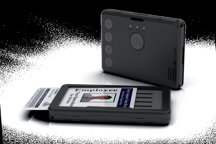
Автономный трекер TELTONIKA GH5200 с GNSS
![]()
GH5200 — автономный персональный трекер для защиты одиночек.
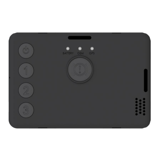
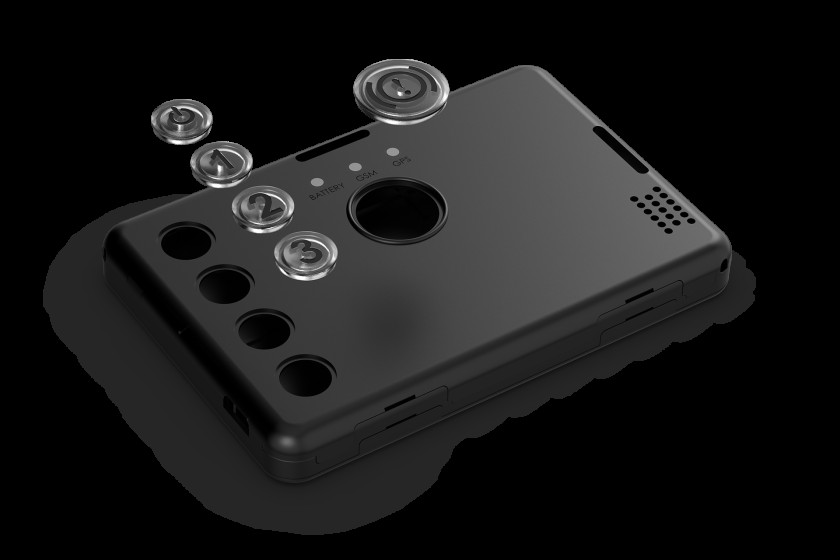
Знай свое устройство

Настройте свое устройство
Как вставить карту Micro SIM и подключить аккумулятор
- Снимите крышку.
- Вставьте карту Micro-SIM, как показано, с отключенным запросом PIN-кода. Убедитесь, что срезанный угол карты Micro-SIM направлен вперед в слот.
- Вставьте аккумулятор в устройство, как показано на рисунке. Разместите аккумулятор в месте, где он не мешает другим компонентам.
- Снова установите крышку и затяните винт.

- Установка/извлечение карты Micro-SIM должна выполняться при включенном питании устройства и отсоединенном аккумуляторе. В противном случае карта Micro-SIM может быть повреждена или устройство не обнаружит ее.
Подключение к ПК (Windows)
- Включите устройство, удерживая кнопку питания около 7 секунд.
- Подключите устройство к компьютеру с помощью кабеля Micro-USB или соединения Bluetooth:
- Использование кабеля Micro-USB
- Вам потребуется установить USB-драйверы, см. «Как установить USB-драйверы (Windows)» ниже.
- Использование Bluetooth
- GH5200 Bluetooth включен по умолчанию. Включите Bluetooth на ПК, затем выберите Добавить Bluetooth или другое устройство > Bluetooth. Выберите свое устройство с именем —
- «GH5200_last_7_imei_digits», без LE в конце. Введите пароль по умолчанию 5555, нажмите Подключить и выберите Готово.
- Теперь вы готовы использовать устройство на своем компьютере.
Как установить драйверы USB (Windows)
- Загрузите драйверы COM-порта отсюда. здесь (https://teltonika-gps.com/downloads/en/fmb120/TeltonikaCOMDriver.zip).2. Извлеките и запустите TeltonikaCOMDriver.exe.
- Нажмите Далее в окне установки драйвера.
- . В следующем окне нажмите кнопку Установить. Программа установки продолжит установку драйвера, и, в конце концов, появится окно подтверждения. Нажмите Готово, чтобы завершить настройку.
Конфигурация (Windows)
На устройстве GH5200 будут установлены заводские настройки по умолчанию. Эти настройки должны быть изменены в соответствии с потребностями пользователя. Основная конфигурация может быть выполнена с помощью программного обеспечения Teltonika Configurator. Конфигуратор работает на ОС Microsoft Windows и использует необходимый MS .NET Framework. Убедитесь, что у вас установлена правильная версия.![]()
Скачанный Конфигуратор будет в сжатом архиве. Распакуйте его и запустите Congurator.exe. После запуска программы язык можно изменить, нажав в правом нижнем углу:![]()
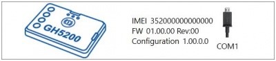
Процесс настройки начинается с нажатия на подключенном устройстве:![]()
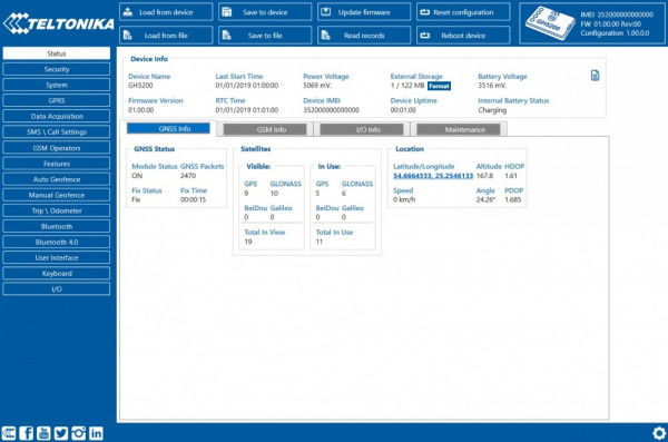
После подключения к Concurator появится окно Статус:![]()
Различные вкладки с информацией о состоянии отображают информацию о GNSS, GSM, вводе-выводе, обслуживании и т. д. GH5200 имеет один редактируемый пользователем профиль, который можно загрузить и сохранить на устройстве. После любого изменения собрания изменения необходимо сохранить на устройстве с помощью кнопки «Сохранить на устройстве». Основные кнопки следующего функционала:
- Загрузить с устройства — загружает конфигурацию с устройства.
- Сохранить на устройство — сохраняет конфигурацию на устройство.
- Загрузить из файла – загружает конфигурацию из файла.
- Сохранить в файл – сохраняет конфигурацию в файл.
- Обновить прошивку – обновляет прошивку на устройстве.
- Чтение записей – чтение записей с устройства.
- Reboot device — перезагружает устройство.
- Сбросить конфигурацию — устанавливает конфигурацию устройства по умолчанию.
Наиболее важным разделом конфигуратора является GPRS, где можно настроить все параметры вашего сервера и GPRS, и сбор данных, где можно настроить параметры сбора данных. Более подробную информацию о настройке GH5200 с помощью конфигуратора можно найти здесь.
Быстрая настройка SMS
Конфигурация по умолчанию имеет оптимальные параметры для обеспечения наилучшего качества трека и использования данных. Быстро настройте свое устройство, отправив на него эту SMS-команду
Параметры конфигурации по умолчанию
Обнаружение движения:
- Движение устройства будет определяться акселерометром
- Устройство делает запись о перемещении, если происходит одно из этих событий.
- Угловая разница между последней координатой
- Прошло 300 секунд, а текущее положение больше 10°.
- Пройденное расстояние более 100 метров
- Разница в скорости между последней координатой и текущим положением больше 10 км/ч
- Проходит 1 час, пока устройство неподвижно
- Отправка записей на сервер:
- Если устройство сделало запись, она отправляется на сервер каждые 120 секунд.
Информация по технике безопасности
Это сообщение содержит информацию о том, как безопасно эксплуатировать GH5200. Соблюдая эти требования и рекомендации, вы избежите опасных ситуаций. Вы должны внимательно прочитать эти инструкции и строго следовать им перед эксплуатацией устройства!
Меры предосторожности
- Эксплуатируйте устройство в подходящих условиях
- Не используйте устройство там, где запрещена мобильная связь.
- Безопасность дорожного движения Соблюдайте местные законы, всегда держите руки на рулевом колесе при использовании устройства. Ваша безопасность имеет первостепенное значение, когда вы едете.
- Помехи Все беспроводные устройства чувствительны к электромагнитным помехам, поэтому беспроводные устройства влияют на работу друг друга.
- Ограничьте использование устройства в больницах Пожалуйста, соблюдайте все ограничения. При необходимости поворачивайте устройство рядом с медицинскими приборами.
- Ограничьте использование устройства в транспортных средствах Пожалуйста, соблюдайте все ограничения. Беспроводные устройства могут создавать помехи для другого электронного оборудования в транспортных средствах.
- Будьте осторожны вблизи легковоспламеняющихся материалов и жидкостей Меры предосторожности при зарядке Зарядные устройства SELV LPS, персональные компьютеры или ноутбуки, к которым будет подключаться устройство, должны соответствовать требованиям стандарта IEC 60950:2005.
- Используйте только оригинальные батареи. Использование батарей несертифицированного производителя или батарей другого типа может привести к взрыву.
- Берегите аккумуляторы от влаги. При хранении поместите их в прохладное и сухое место. Избегайте длительной эксплуатации при высоких температурах. Не пытайтесь заряжать аккумулятор напрямую от электросети. Все используемые батареи должны соответствовать IEC 62133.
- Блоки питания Цепи питания, используемые для зарядки устройства, должны иметь защиту, предотвращающую утечку питания, короткие замыкания или неправильное электрическое заземление. Все бывшие в употреблении выключатели должны быть установлены в легкодоступном месте. Питание должно быть бесперебойным, а расстояние между контактами должно быть не менее 3 мм.
- Безопасное извлечение устройства Устройство должно быть отключено от компьютера или зарядного устройства, отсоединив магнитный USB-кабель от устройства.
- Во избежание механических повреждений устройство рекомендуется транспортировать в ударопрочной упаковке. Если устройство перестало работать должным образом независимо от настроек, помочь может только квалифицированный специалист. В таком случае рекомендуется связаться с местным продавцом или менеджером UAB Teltonika.
- Используйте правильную отвертку Во избежание механических повреждений крышки устройства рекомендуется использовать отвертку, которая входит в комплект поставки. Не используйте электрические отвертки.
- https://wiki.teltonika-mobility.com/view/GH5200 Получено с сайта “https://wiki.teltonika-mobility.com/wikibase/index.php?title=GH5200_First_Start&oldid=62091″
Документы / Ресурсы
Рекомендации