
Код: 4825
Снят с производства
| Производитель | FOIF |
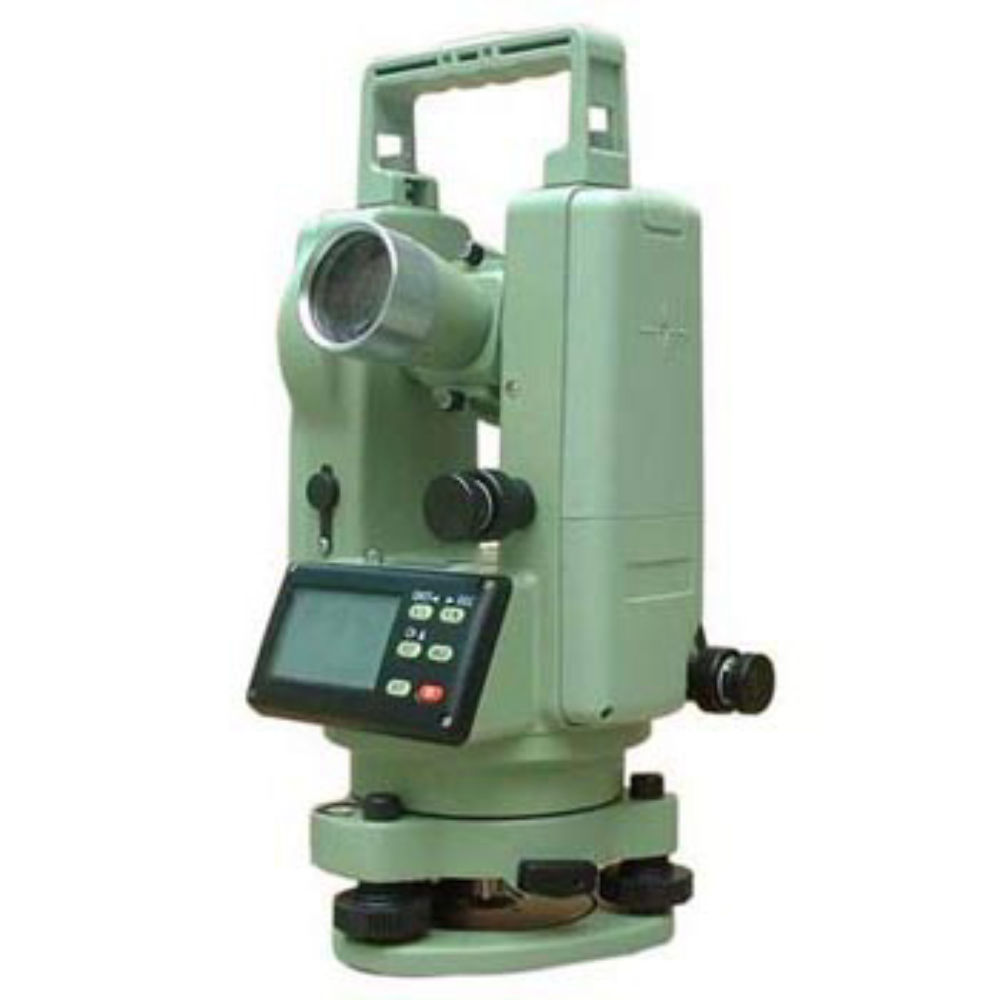
| Артикул | DT202C |
Добро пожаловать!
Войдите или зарегистрируйтесь сейчас!
Войти
-

- Регистрация:
- 7 апр 2019
- Сообщения:
- 3
- Симпатии:
- 0
Кроме известных параметров, которые прописаны в инструкции (там только одна строка; скрин прилагаю), есть ещё (нижняя строка, два значения, тоже 0 или 1; фото прилагаю). Менял их, но так и не понял, что изменилось.
К примеру, на смену начала отсчёта вертикальных углов (горизонт/зенит) они не повлияли.
Прошу помочь с информацией.Вложения:
#1
-

Форумчанин
- Регистрация:
- 15 дек 2014
- Сообщения:
- 1.241
- Симпатии:
- 1.022
- Адрес:
-
Москва
Таблица почему-то урезанная, вот вариант полной (хотя сама инструкция далеко не полная!)
Вложения:
#2
-
- Регистрация:
- 7 апр 2019
- Сообщения:
- 3
- Симпатии:
- 0
Спасибо, теперь разобрался! А ссылку на скачивание полной инструкции Вы не могли бы указать?
Я сделал вывод, что те, которые у меня, или устарели или урезаны (они и в бумаге и на компе).#3
Поделиться этой страницей
-
Contents
-
Table of Contents
-
Bookmarks
Quick Links
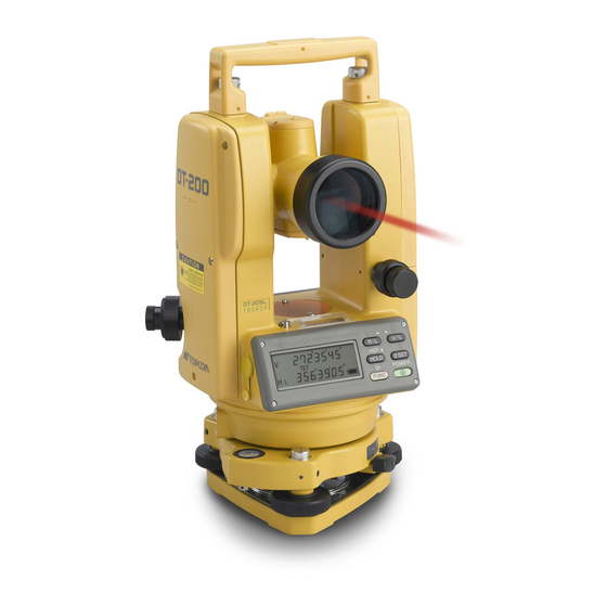
INSTRUCTION MANUAL
DIGITAL THEODOLITE
DT-200/200L
SERIES
Related Manuals for Topcon DT-200 series
Summary of Contents for Topcon DT-200 series
-
Page 1
INSTRUCTION MANUAL DIGITAL THEODOLITE DT-200/200L SERIES… -
Page 3: Foreword
FOREWORD Thank you for purchasing the TOPCON Digital Theodolite. For the best per- formance of the instruments, please carefully read these instructions and keep them in a convenient location for future reference.
-
Page 4: General Handling Precautions
General Handling Precautions Before starting work or operation, be sure to check that the instrument is functioning correctly with normal performance. Do not submerge the instrument into water. The instrument can not be submerged underwater. The instrument is designed based on the International Standard IP66, therefore it is protected from the normal rainfall.
-
Page 5
Notice on Transceiver When using high output transceiver etc., make sure it does not come near the instrument. Opening the carrying case When opening the carrying case and taking out the instrument, place the case horizontally, then open the case. -
Page 6: Display For Safe Use
•There is a risk of fire, electric shock or physical harm if you attempt to disassemble or repair the instrument yourself. This is only to be carried out by TOPCON or an authorized dealer, only! •Laser beams can be dangerous, and can cause eye injury’s if used incorrectly.
-
Page 7
•Battery can cause explosion or injury. Do not dispose in fire or heat. •Risk of fire or electric shock. Do not use any power voltage except the one given on manufactur- ers instructions. •Battery can cause outbreak of fire. Do not block up the vent of the battery. •The short circuit of a battery can cause a fire. -
Page 8: Laser Safety
The laser beam belongs not very dangerous type but we request you to keep and understand “Safety standard for users” as mentioned in the manual instruction. In case of any failure, do not disassemble the instrument. Contact TOPCON or your TOPCON dealer. Labels Find the labels which describes the caution and safety about the laser beam as follows in DT-205L/207L/209L.
-
Page 9: User
User 1) This product is for professional use only! The user is required to be a qualified surveyor or have a good knowledge of surveying, in order to understand the user and safety instructions, before operating, inspecting or adjusting. 2) Wear the required protectors (safety shoes, helmet, etc.) when operating. Exceptions from Responsibility 1) The user of this product is expected to follow all operating instructions and make periodic checks of the product’s performance.
-
Page 10: Table Of Contents
Contents FOREWORD ………………….1 General Handling Precautions …………..2 Display for Safe Use ……………… 4 Safety Cautions ………………4 Laser Safety ………………..6 User ………………….7 Exceptions from Responsibility …………..7 Contents ………………..8 Standard Set Composition …………….. 9 NOMENCLATURE AND FUNCTIONS ………… 10 1.1 Nomenclature ………………
-
Page 11: Standard Set Composition
Standard Set Composition The numerical value in parentheses shows the quantity. Instrument Carrying case with lens cap Plumb bob set Tool kit Cleaning brush, Screw driver, Rod pins, Plumb bob hook (Hexagonal wrench : Only for DT-205/207/209/209P) AA batteries (4) Plastic rain cover (1) Silicon cloth Instruction manual (1)
-
Page 12: Nomenclature And Functions
NOMENCLATURE AND FUNCTIONS 1.1 Nomenclature Sighting collimator DT-205/207/209/209P Instrument Objective lens height mark Display window *1) Horizontal tangent screw Optical plummet telescope Tribrach fixing lever (205/207 only) Horizontal Circular level motion clamp *1) DT-209/209P has one side display only. Leveling screw Centering screw (209P only)
-
Page 13
Handle Handle fixing knob Telescope focusing knob Cross-hair adjustment section cover Telescope eyepiece Battery Vertical motion clamp Vertical tangent screw Plate level Operation keys RS-232C Connector Base (205 only) Tribrach type DT-205/207: Detachable Plate level DT-209: Fixing (207 only) DT-209P: Centering… -
Page 14
DT-205L/207L/209L Sighting collimator Instrument Objective lens height mark Horizontal motion clamp Horizontal tangent screw Optical plummet telescope Display window *1) Leveling screw Circular level Tribrach fixing lever (205L/207L only) *1) DT-209L has one side display only. -
Page 15
Handle Handle fixing knob Telescope focusing knob Cross-hair adjustment section cover Telescope eyepiece Battery Vertical motion clamp Vertical tangent screw Laser axis adjusting screw (with cap) Plate level Operation keys Base Tribrach type RS-232C Connector DT-205L/207L: Detachable (205L only) DT-209L: Fixing Plate level (207L only) -
Page 16: Display
1.2 Display Display marks Display Contents Display Contents Tilt correction mode Vertical angle TILT (DT-205/205L only) Function key selection Horizontal angle right mode Horizontal angle left Percent grade Repetition angle mea- Unit display GON surement The number of repeti- 8AVG tion / Average of angle 1.3 Operating keys Function mode…
-
Page 17
Adjustment mode and Selecting mode Mode Adjustment mode of vertical angle 0 Turn the power ON while pressing datum the [0 SET] key. Turn the power ON while pressing Selecting mode 1 the [R/L] key. Turn the power ON while pressing Selecting mode 2 the [V/%] key. -
Page 18: Preparation For Measurement
PREPARATION FOR MEASUREMENT 2.1 Setting Instrument Up for Measurement Setting up the Tripod First, extend the extension legs to suitable lengths and tighten the screws on their midsections. Attaching the Instrument on the Tripod Head Place the instrument carefully on the tripod head and slide the instrument by loosening the tripod screw.
-
Page 19
Centering by Using the Plate Level 1) Rotate the instrument horizontally by using the Horizontal motion/clamp screw and place the plate level parallel with the line connecting leveling screws A and B, and then bring the bubble to the center of the plate level by turning leveling screws A and B. -
Page 20: Power Switch Key On
2.2 Power Switch Key ON Confirm the instrument is leveled. Turn the power switch ON. Every segment turns on for about 1 second. Battery Power 342°03’41” Remaining Display Press the [V/%] key. The vertical angle is displayed. 11°50’28” 342°03’41” ● Confirm the battery power remaining on the display. Replace with charged battery or charge when battery level is low.
-
Page 21: Battery Level Indicator
2.3 Battery Level Indicator The battery power indicator shows the level of battery strength. 90°10’20” TILT Measurement is possible. 123°40’50” Battery Power Measurement is impossible. Remaining Display Need to recharge or replace the battery. 1) The battery operating time will vary depending on the environmental conditions, such as ambient temperature etc.
-
Page 22: Measurement
MEASUREMENT 3.1 Measuring Horizontal Angle Right and Vertical Angle Collimate the first target «A». 90°10’20” 120°30’40” Press the [0 SET] key twice to set the horizontal angle of target «A» at 0 ° 00′ 00″. 90°10’20” 0°00’00” • One time pressing [0 SET] function is available. Refer to «6 SELECTING MODE».
-
Page 23: Switching Horizontal Angle Right / Left
3.2 Switching Horizontal Angle Right / Left Collimate the first target «A». 90°10’20” 120°30’40” Press the [R/L] key. The mode Horizontal angle right (HR) switches to Horizontal angle left (HL) 90°10’20” 239°29’20” • Every time pressing the [R/L] key, HR/HL mode switches. Measure as HR mode.
-
Page 24: Measuring From The Required Horizontal Angle
3.3 Measuring from the Required Horizontal Angle Display the required horizontal angle using the horizontal motion clamp and horizontal tangent screw. 90°10’20” 130°40’20” Press the [HOLD] key. The display of horizontal angle blinks and the horizontal angle will be held. 90°10’20”…
-
Page 25: Repetition Angle Measurement
3.5 Repetition Angle Measurement Press the [FUNC] key. 90°10’20” 120°30’40” Press the [REP] key. 0°00’00” Collimate the target «A», and press the [0SET] key twice. 0°00’00” Collimate the target «B», and press the [HOLD] key. 45°10’00” 1AVG 45°10’00” Recollimate the target «A» and press the [R/L] key. Recollimate the target «B», and press the [HOLD] key.
-
Page 26
Repeat the procedure to measure the desired number of repetition. 180°40’00” 4AVG 45°10’00” Example: 4 measurements To finish the repetition measurement, press the [FUNC] key and press the [HOLD] key. • Horizontal angle can be accumulated up to (2000°00’00» – minimum reading) (horizontal angle right). In case of 5 second reading, horizontal angle can be accumulated up to +1999°59’55». -
Page 27: Stadia Surveying
3.6 Stadia Surveying This instrument can be used for stadia surveying, Measurement by stadia is a convenient method for measuring distances with the stadia hairs of the instrument, in combination with a graduated rod, such as a leveling rod or stadia rod, which is preferable for long distances.
-
Page 28: How To Operate The Laser
HOW TO OPERATE THE LASER (DT-205L/207L/209L only) WARNING Aiming the instrument into prism or highly reflective sur- face can result in serious damage to your eye because the optical axis and laser beam source is in coincidence. Do not aim the instrument directly into prism or highly reflective sur- face.
-
Page 29: The Other Functions
THE OTHER FUNCTIONS 5.1 Buzzer Sounding for Horizontal Angle 90° Increments When the horizontal angle falls in the range of less than ± 1° of 0°, 90°, 180° or 270°, the buzzer sounds. Buzzer stops only when the horizontal angle is adjusted to 0°00’00”, 90°00’00”…
-
Page 30: Detach / Attach Of Tribrach
5.5 Detach / Attach of Tribrach Only for detachable tribrach type Alignment piece Tribrach alignment groove Securing screw Tribrach fixing lever The instrument is easily detached or attached to the tribrach, with a tribrach locking lever loosened or tightened for this purpose. ●…
-
Page 31: Selecting Mode
SELECTING MODE The following modes are available 6.1 Items of the Selecting Mode Selecting mode 1 To set the instrument the selecting mode 1, turn the power ON while press- ing the [R/L] key. Selecting mode 1 [R/L] key + Power on 0 0 0 0 0 0 0 Digit No.7 Digit No.1…
-
Page 32
Selecting mode 2 To set the instrument the selecting mode 2, turn the power ON while press- ing the [V/%] key. Selecting mode 2 [V/%] key + Power on 0 0 0 0 0 0 0 Digit No.7 Digit No.1 Selecting mode 2 Digit Items… -
Page 33: How To Set The Selecting Modes
6.2 How to Set the Selecting Modes ● Selecting Mode 1 Sample setting: Auto cut off : OFF, 90 ° buzzer : OFF Turn the power ON while pressing the [R/L] key. The instrument will be in the selecting mode 1, and the digit No.1 will blink.
-
Page 34
Press the [0 SET] key to set the setting. S E T 0 1 0 0 1 0 0 Turn the power off. -
Page 35
● Selecting mode 2 Sample setting: [0 SET] key pressing : Once, Tilt correction : OFF Turn the power ON while pressing the [V/%] key. The instrument will be in the selecting mode 2, and the digit No.1 ( 0set key pressing) will blink. 0 0 1 0 0 0 0 Blinking Press the [… -
Page 36: Handling Power Source
HANDLING POWER SOURCE 7.1 For removing Push the lock lever downward and pull out the battery. Lock lever 7.2 Replace the battery (DB-35) Hole Convex Hook Push the hook downward and take the lid out. Take out the old batteries and put new batteries as illustration shows in direction of plus and minus sides Insert a convex in a upper hole.
-
Page 37: Check And Adjustment
CHECK AND ADJUSTMENT ● Pointers on the Adjustment Adjust the eyepiece of the telescope properly prior to any checking operation which involves sighting through the telescope. Remember to focus properly, with parallax completely eliminated. Carry out the adjustments in the order of item numbers, as the adjustments are dependent one upon another.
-
Page 38: Checking /Adjusting The Plate Level
8.1 Checking /Adjusting the Plate Level Adjustment is required if the axis of the plate level is not perpendicular to the vertical axis. ● Check Place the plate level parallel to a line running through the centers of two leveling screws, say, A and B. Use these two leveling screws only and place the bubble in the center of the plate level.
-
Page 39: Checking And Adjusting The Circular Level
8.2 Checking and Adjusting the Circular Level ● Checking Carefully level the instrument with the plate level only. If the bubble of the circular level is centered properly, adjustment is not required. Otherwise, proceed with the following adjustment. ● Adjustment Shift the bubble to the center of the circular level, by adjusting three capstan adjustment screws on the bottom surface of the circular level, with the accessory adjusting pin.
-
Page 40: Adjustment Of The Vertical Cross-Hair
8.3 Adjustment of the Vertical Cross-hair Adjustment is required if the vertical cross-hair is not in a place perpendicu- lar to the horizontal axis of the telescope ( since it must be possible to use any point on the hair for measuring horizontal angles or running lines). ●…
-
Page 41
Check once more and if the point travels the entire length of the vertical cross-hair, further adjustment is not required. Eyepiece section attachment screws Eyepiece Perform following adjustment after completing the above ad- justment . Section 8.4 “Collimation of the Instrument”, Section 8.6 “Ad- justment of Vertical Angle 0 Datum”. -
Page 42: Collimation Of The Instrument
8.4 Collimation of the Instrument Collimation is required to make the line of sight of the telescope perpendicu- lar to the horizontal axis of the instrument, otherwise, it will not be possible to extend a straight line by direct means. ●…
-
Page 43
● Adjustmen Unscrew the cross-hair adjustment section cover. Find Point D at a point between Points C and B, which should be equal to 1/4th the distance between Points B and C and measured from Point C. This is because the apparent error between Points B and C is four times the actual error since the telescope has been reversed twice during the checking… -
Page 44: Checking And Adjusting The Optical Plummet Telescope
8.5 Checking and Adjusting the Optical Plummet Telescope Adjustment is required to make the line of sight of the optical plummet tele- scope coincide with the vertical axis ( otherwise the vertical axis will not be in the true vertical when the instrument is optically plumbed). ●…
-
Page 45: Adjustment Of Vertical Angle 0 Datum
8.6 Adjustment of Vertical Angle 0 Datum If when measuring the vertical angle of target A at telescope position normal (direct) and reverse settings, the amount of normal and reverse measure- ments combined is other than 360° (ZENITH-0), half of the difference from 360°…
-
Page 46: Adjustment Of Laser Beam
8.7 Adjustment of Laser Beam This adjustment must be done after completing following checking and adjusting. 8.3 “Adjustment of the Vertical Cross-hair”, 8.4 “Collimation of the Instrument”. WARNING ● Aiming the instrument into prism or highly reflective surface can re- sult in serious damage to your eye because the optical axis and la- ser beam source is in coincidence.
-
Page 47: Storage Precautions
STORAGE PRECAUTIONS ● When returning the instrument to its case, be sure to match the white posi- tioning marks provided with the case and place the instrument with the eye- piece upward. ● For cleaning the instrument after use, remove dust using a cleaning brush, then wipe off with a cloth.
-
Page 48: Optional Accessories
10 OPTIONAL ACCESSORIES Diagonal Eyepiece, Model 13 The diagonal eyepiece is used in place of the telescope eyepiece for making observations up to the zenith. Instrument eyepiece Diagonal eyepiece, model 13 Trough Compass model 5 The trough compass is simply mounted on top of the carrying handle. Back pack When transporting the instrument with this back pack, it is very convenient for carrying the instrument on the shoulder.
-
Page 49: Error Display
«Adjustment Confirm the procedure and adjust of Vertical Angle 0 Datum» is again. operated, or horizontal angle is set zero or hold. • If errors still persist after attempting to clear them, contact your dealer or TOPCON.
-
Page 50: Specifications
12 SPECIFICATIONS (DT-205/207/209/209P) Model Item Item DT-209/ DT-205 DT-207 209P Telescope Length 149mm 149mm 149mm Objective lens 45mm 45mm 40mm Magnification 30× 30× 26× Image Erect Erect Erect Field of view 1° 30′ 1° 30′ 1° 30′ Resolving power 2.5″ 2.5″…
-
Page 51
Model Item Item DT-209/ DT-205 DT-207 209P Others Dimension 149x188x313 149x188x313 DT-209: 149x188x305 DxWxH(mm) (5.87×7.1×12.3 in) (5.87×7.1×12.3 in) (5.87×7.1×12.0 in) DT-209P: 149x188x313 (5.87×7.1×12.3 in) Weight (Includ- 4.1kg 4.1kg DT-209: 3.4kg (7.5 lb) ing batteries) (9.0 lb) (9.0 lb) DT-209P: 3.8kg (8.3 lb) Instrument height 176 mm 176 mm… -
Page 52
Model Item Item DT-205L DT-207L DT-209L Optical Magnification Plummet Filed of view 3° 3° 3° Telescope Focusing 0.5m~∞ 0.5m~∞ 0.5m~∞ Level Plate level 40″/2 mm 40″/2 mm 60″/2 mm Sensitivity Circular level 10’/2mm 10’/2mm 10’/2mm Water protection Standard IP 66 IP 66 IP 66 Power Supply… -
Page 53
TOPCON (GREATBRITAIN) LTD. TOPCON POSITIONING SYSTEMS, INC. HEAD OFFICE 5758 West Las Positas Blvd., Pleasanton, CA 94588, U.S.A. Topcon House Kennet Side, Bone Lane, Newbury, Berkshire RG14 5PX U.K. Phone: 925-460-1300 Fax: 925-460-1315 www.topcon.com Phone: 44-1635-551120 Fax: 44-1635-551170 TOPCON CALIFORNIA survey.sales@topcon.co.uk laser.sales@topcon.co.uk…
Теодолит электронный FOIF DT202C — оснащены большим жидкокристаллическим дисплеем, съёмным треггером и большим жидкокристаллическим дисплеем. Зрительная труба 30Х увеличения даёт четкое и яркое изображение, за счет высококачественной оптики. Этот геодезический прибор разрабатывается и собирается высококвалифицированными инженерами на заводе FOIF (Китай) по лицензии (на оптику) фирмы LEICA. (Швейцария). Цифровое значение горизонтальных и вертикальных углов отображается на жидкокристаллическом дисплее. Это весьма полезная функция полностью исключает ошибку при считывании результатов измерений. Методика измерения — абсолютное считывание углов. Электронные теодолиты FOIF серии DT 200 имеют автоматический компенсатор, порт передачи данных RS-232C обеспечивает использование с внешними устройствами.
Теодолит электронный FOIF DT202C имеет надёжную пыле и влагозащиту, аккумуляторы обеспечивают непрерывную работу в течение 8 часов, вес — 4.8 кг. Все эти положительные качества делают геодезический прибор FOIF DT-202,205 удобным в экспедиционных и полевых условиях. Так же этот прибор широко зарекомендовал себя при строительстве сооружений, объектов, инженерных изысканиях, монтаже промышленного оборудования, высокоточных измерения.
Вы можете оплатить товар — одним из нескольких вариантов оплаты:
Наличный вариант расчета. Данный вариант расчета доступен только для заказов по Москве и Московской области. Вы оплачиваете заказ курьеру наличными или банковской картой. Курьер предоставляет следующие сопроводительные документы:
- Для физических лиц — кассовый и товарный чеки;
- Для юридических лиц — приходный кассовый ордер, кассовый чек, товарная накладная и счет-фактура.
Безналичный вариант расчета. Доставка заказа осуществляется только после поступления средств на р/с компании.
- Для физических лиц — Счет, УПД, кассовый чек. Оплатить можно через любое отделение банка, принимающее платежи от физических лиц. Внимание! При переводе банк может взимать комиссию.
- Для юридических лиц — счет, УПД.
Условия доставки:
- Бесплатная доставка до офиса СДЭК (стоимость услуг СДЭК оплачивается при получении в выбранном вами пункте выдачи)
- Бесплатная доставка по Москве (в пределах МКАД) для заказов суммой более 30000 руб.
- Стоимость доставки по Москве (в пределах МКАД) — 500 руб.
- Доставка по Московской области (за МКАД) рассчитывается индивидуально, в зависимости от удаленности района.
- Бесплатная Авто/ЖД доставка по России происходит после 100%-ной предоплаты в течение 3-7 дней, для заказов суммой более 100 000 руб.
- Стоимость Авто/ЖД доставки по России для заказов суммой менее 100 000 руб рассчитывается в индивидуальном порядке.
Компания «ГеоТах» сотрудничает со следующими транспортными компаниями:
- «Деловые линии»
- «СДЭК»
- «Первая экспедиционная компания (ПЭК)»
- Скоростная доставка по России от 1-3 дней осуществляется компанией «City Express».
Возможна срочная доставка по Москве курьерской службой «Достависта» — подробности у нашего менеджера
Самовывоз осуществляется с нашего склада по адресу: г. Москва, ул. Иркутская 11, к. 1, оф. 411.

прибор
прибор с поверкой
3 в 1
- Описание
- Отзывы
Увеличение зрительной трубы 30х
- Условия окружающей среды, рабочая температура От -20°С до +50°С
- Дисплей ЖКЭ со светодиодной подсветкой, два
- Точность угловых измерений 2”
- Наименьший угловой отсчет 1”
- Диапазон работы компенсатора ±3’
- Время непрерывной работы 80ч.
- Минимальное расстояние фокусировки 1м
- Питание NI-MH аккумулятор или 4 алкалиновые батареи типа АА
- Передача данных Через RS-232C порт
- Вес 4,8кг
Электронные теодолиты серии DT200 предназначены для измерения вертикальных и горизонтальных углов.
Прибор выполняет измерения, вычисления, отображает и сохраняет полученные данные с помощью компьютерных технологий.
При использовании электронных теодолитов исключаются ошибки снятия отсчетов — значения углов выводятся на дисплей,
расположенный с двух сторон прибора. Предусмотрена установка нулевого значения на исходное направление и фиксирование
отсчета по горизонтальному кругу. Применяются для триангуляции III-IV класса, в строительстве, в инженерных изысканиях,
для кадастровой, топографической и других видов съемок.
Прибор зарегистрирован в Государственном реестре средств измерений под № 34772-07 и допущен к
применению в Российской Федерации.
Просмотренные товары
-

Точность угловых измерений 2”
Диапазон работы компенсатора ±3’прибор
с поверкой
3 в 1