Терморегулятор EBERLE ITR 3 ( +40 до +100)
Терморегулятор EBERLE ITR 3 ( +40 до +100)- Универсальный, электронный регулятор температуры. Устанавливается в бокс на DIN-рейку. Укомплектован выносным датчиком температуры, с фиксацией режима. Применяется для управления температурным режимом в: электроустановках, производственных помещениях, распределительных щитах и для защиты от промерзания трубопроводов, водостоков. Диапазон управления температурой +40 + 100°С.
Технические характеристики:
Диапазон регулировки +40 до +100 оС
Тип — промышленный
Длина выносного датчика 1,5 м (наращивать рекомендовано до 50 м)
Ток 10 (4) А
Напряжение 230 В
Частота 50-60 Гц
Класс защиты IP 40
Один переключатель свободный от напряжения
Передающий дифференциал ~ 1К
Ограничение дипазона с шагом 5К
Световой индикатор
Класс защиты IP 40 в соответствии с EN 60529
Габариты 70×36×75 мм
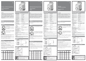
Схема подключения Габаритные размеры


Написать отзыв
Ваше Имя:
Ваш отзыв:
Внимание: HTML не поддерживается! Используйте обычный текст.
Оценка: Плохо
Хорошо
Введите код, указанный на картинке:
Montage- und Bedienungsanleitung
Temperaturregler ITR 3
528 35
U 468 931 001 311-6
Montage
Der Regler wird auf 35 mm Normschiene aufgeschnappt. Der
elektrische Anschluss erfolgt entsprechend dem aufgedruck-
ten Schaltbild.
Funktionen
Die gewünschte Temperatur wird mit-
tels Drehknopf an der Frontseite des
Reglers eingestellt.
Diese Einstellung kann mittels der
Taste unterhalb des Einstellknopfes
arretiert werden.
Ebenso ist eine Bereichseinengung
möglich. Diese wird in 5°C—Teilen
durch die Stifte an der Temperatur-
skala vorgenommen.
Bitte beachten Sie: Arretierung und Bereichseinengung
dienen als Schutz gegen unbeabsichtigtes Verstellen.
Betätigen Sie den Einstellknopf niemals gewaltsam. Lässt sich
dieser nicht oder nur schwer betätigen, überprüfen Sie, ob
eine der beiden Arretierungsfunktionen betätigt ist.
Bis die eingestellte Temperatur erreicht wird, sind die
Kontakte 2 und 3 geschlossen. Die grüne LED leuchtet.
Fernfühler
Bei Einsatz des Standardfühlers in Flüssigmedien ist die
Verwendung eines Schutzrohres erforderlich.
Ein Rohranlegefühler soll möglichst großflächig an dem zu
regelnden Rohr anliegen.
Bei Einsatz des Luftfühlers ist darauf zu achten, dass die
Schlitzöffnungen in der Luftströmung liegen.
Das Fühlerkabel kann bei einem Querschnitt von 1,5 mm
2
bis
auf 50 m verlängert werden, ohne die Genauigkeit des
Reglers zu beeinträchtigen. Bei Verlegen des Fühlerkabels in
Kabelkanälen oder in der Nähe von Starkstromleitungen
muss eine abgeschirmte Leitung verwendet werden. Der
Schirm ist an Klemme 4 anzuschließen.
Fühlerkenndaten
R R R
(°C) (Ω) (°C) (Ω) (°C) (Ω)
–55 500 25 1000 110 1774
–50 525 30 1039 120 1882
–40 577 40 1118 125 1937
–30 632 50 1202 130 1993
–20 691 60 1288 140 2107
–10 754 70 1379 150 2225
0 820 80 1472 160 2346
10 889 90 1569 170 2471
20 962 100 1670 175 2535
Achtung!
Dieses Gerät darf nur durch einen Fachmann gemäß
dem Schaltbild am Gehäuse installiert werden. Dabei
sind die bestehenden Sicherheitsvorschriften zu beach-
ten.
Dieser zum Schalttafeleinbau bestimmte elektronische
Regler ist geeignet zur Montage in trockenen und
geschlossenen Räumen mit üblicher Umgebung. Der
Regler arbeitet nach der Wirkungsweise 1 C.
Technische Daten
Netzversorgung
Nennspannung AC 220/230 V
Toleranzbereich 187 … 242 V
Nennspannung AC 240 V
Toleranzbereich 204 … 264 V
Nennspannung AC 110/115 V
Toleranzbereich 93 … 127 V
Nennspannung AC 24 V
Toleranzbereich 20,4 … 26,4 V
Frequenz 50/60 Hz
Frequenzbereich 48 … 62 Hz
Nennspannung DC 24 V
Toleranzbereich 21,6 … 26,4 V
Schaltvermögen AC 250 V, 10 (4) A
Temperaturbereiche
Sollwertangabe –40 … 20°C / 0 … 60 °C
20 … 80°C / 40 … 100°C
100 … 160°C
Umgebungstemperatur
Betrieb –10 … 50°C
Lagerung –40 … 70 °C
Stat. Hysterese 1 K
Kontaktart 1 Wechsler potentialfrei*
Bemessungsstoßspannung 2,5 KV
Temperatur für die
Kugeldruckprüfung 75°C
Spannung und Strom für 230V, 10A
Zwecke der EMV—
Störaussendungsprüfungen
*) Achtung
Die potentialfreien Kontakte dieses netzbetriebenen Gerätes ge-
währleisten nicht eine mögliche Forderung nach Schutzklein-
spannung (sichere Trennung).
Maßskizze
Schaltbild
HINWEIS:
Bei der 24 V—Version muss die Versorgung aus einem
Schutzkleinspannungsnetz erfolgen.
Notice de
montage et d’utilisation
Thermostat ITR 3
528 35
U 468 931 001 311-6
Montage
Sur rail DIN de 35 mm. Le branchement doit être fait selon le
schéma qui se trouve sur l’appereil.
Fonction
La température souhaitée est affichée
par le bouton en facade. Ce réglage
peut être bloqué par la touche située
sous le bouton.
Il est également possible de choisir
une plage de réglage de température
par l’intermédiaire de picots, par
intervalles de 5°C.
Ces deux possibilités sont prévues
pour éviter tout dérèglement accidentel de la température
progammée.
Ne pas forcer le bouton de réglage; si celui-ci offre une rési-
stance, contrôler si aucune des sécurités n’est mise.
Sonde ą distance
La sonde standard ne peut être utilisée dans un milieu liqui-
de qu’à l’intérieur d’un doigt de gant.
La sonde applique doit avoir une surface maximale en
contact avec le tuyan à surveiller.
La sonde pour veine d’air doit être placée de manière à ce
que ses ouvertures soient dans le sens du courant d’air.
Il est possible de rallonger jusqu’à 50 m le câble, en utilisant
un fil de section 1,5 mm
2
sans altérer la précision.
Si le câble est posé dans un chemin de câble ou à proximité
de câbles d’alimentation, il faut employer du câble blindé.
Raccorder le blindage à la borne 4.
Caractéristiques des sondes
R R R
(°C) (Ω) (°C) (Ω)(°C)(Ω)
–55 500 25 1000 110 1774
–50 525 30 1039 120 1882
–40 577 40 1118 125 1937
–30 632 50 1202 130 1993
–20 691 60 1288 140 2107
–10 754 70 1379 150 2225
0 820 80 1472 160 2346
10 889 90 1569 170 2471
20 962 100 1670 175 2535
ATTENTION!
Cet appareil ne peut être monté que par un spécialiste
conformément au schéma de raccordement sur le
boîtier. Respecter les consignes de sécurité en vigueur.
Ce régulateur électronique à montage en tableau est
destiné à être installé dans des locaux secs et fermés
soumis à des conditions usuelles. Ce régulateur fonc-
tionne en mode 1 C.
Caractéristiques techniques
Tension d’alimentation AC 220/230 V
Tolèrance 187 … 242 V
Tension d’alimentation AC 240 V
Tolèrance 204 … 264 V
Tension d’alimentation AC 110/115 V
Tolèrance 93 … 127 V
Tension d’alimentation AC 24 V
Tolèrance 20,4 … 26,4 V
Frequence 50/60 Hz
Tolèrance 48 … 62 Hz
Tension d’alimentation DC 24 V
Tolèrance 21,6 … 26,4 V
Pouvoir de coupure AC 250 V, 10 (4) A
Plages de temperature
Affichage de la –40 … 20°C / 0 … 60 °C
valeur de sonsigne 20 … 80°C / 40 … 100°C
100 … 160°C
Température
Ambiante –10 … 50°C
Stockage –40 … 70°C
Hystèrèsis staique 1 K
Contact 1 inverseur*
Surtension transitoire 2,5 KV
dimensionnée
Température d’essai 75°C
Brinell
Tension et courant de 230 V, 10 A
contrôle decompatibilité
électromagnétique
Plan cote
Schémas de raccordement électrique
REMARQUE:
La version 24 V doit être alimentée par un reseau basse-
tension de sécurité.
Mounting and operating instructions
Thermostat ITR 3
528 35
U 468 931 001 311-6
Mounting
The thermostat is designed for mounting on to 35 mm rail
according to EN 50 022. Electrical connections are according
to the wiring diagram.
Functions
The desired temperature is set via the
knob on the front of the controller.
The setting can be locked with the
button located below the setting
knob. A 5°C limit is possible with the
use of tappets on the temperature
scale.
Please note: Locking and range limits are provided to pro-
tect against incorrect settings. Never turn the setting knob
using force. If it cannot be turned easily, check wheter or not
the control knob is locked.
Contacts 2 and 3 are made until the set temperature is rea-
ched. The green LED lights up.
Remote sensor
When using the standard sensor in liquids a pocket must be
used. The sensor should be in contact with as large a surfa-
ce area as possible.
When using the air sensor it is important that the air ducts
are sited correctly for air flow.
The sensor cable, with a diameter of 1.5 mm
2
, can be exten-
ded up to 50 m without adverse effect on the accuracy of
the controller. When the sensor cable is laid in cable ducts
or near high current cables, it may be necessary to use scre-
ened cable. The screen shall be connected to terminal 4.
Sensor data
R R R
(°C) (Ω) (°C) (Ω) (°C) (Ω)
–55 500 25 1000 110 1774
–50 525 30 1039 120 1882
–40 577 40 1118 125 1937
–30 632 50 1202 130 1993
–20 691 60 1288 140 2107
–10 754 70 1379 150 2225
0 820 80 1472 160 2346
10 889 90 1569 170 2471
20 962 100 1670 175 2535
Note!
This device must be installed by an expert according to
the circuit diagram on the housing. The existing safety
regulations must be complied with. This electronic regu-
lator is designed to be installed in the control panel and
is suitable for installation in dry and closed rooms with
standard atmospheric conditions. The controller works
according to operation method 1C.
Technical Data
Operating voltage AC 220/230 V
Tolerance 187 … 242 V
Operating voltage AC 240 V
Tolerance 204 … 264 V
Operating voltage AC 110/115 V
Tolerance 93 … 127 V
Operating voltage AC 24 V
Tolerance 20.4 … 26.4 V
Frequence 50/60 Hz
Tolerance 48 … 62 Hz
Operating voltage DC 24 V
Tolerance 21.6 … 26.4 V
Switching Capacity AC 250 V, 10 (4) A
Temperature ranges
Nominal value –40 … 20°C / 0 … 60 °C
indication 20 … 80°C / 40 … 100°C
100 … 160°C
Ambient temperature
Operating –10 … 50°C
Storage –40 … 70°C
Static switching
differential 1 K
Contact 1 change over
Rated impulse voltage 2.5 KV
Brinell test temperature 75°C
Voltage and current for 230 V, 10 A
EMC emitted
interference testing
NOTE:
The volt-free contact of this mains operated unit does not ensu-
re the requirement for the use of safety extra-low voltage (SELV).
Dimension drawing
Wiring diagram
NOTE:
24 V Version. Supply has to be made via protected small
voltage mains.
Need a manual for your Eberle ITR 3 528 35 Thermostat? Below you can view and download the PDF manual for free. There are also frequently asked questions, a product rating and feedback from users to enable you to optimally use your product. If this is not the manual you want, please contact us.
Is your product defective and the manual offers no solution? Go to a Repair Café for free repair services.
Manual

Rating
Let us know what you think about the Eberle ITR 3 528 35 Thermostat by leaving a product rating. Want to share your experiences with this product or ask a question? Please leave a comment at the bottom of the page.
Are you satisfied with this Eberle product?
Yes No
Be the first to rate this product
0 votes
Frequently Asked Questions
Our support team searches for useful product information and answers to frequently asked questions. If you find an inaccuracy in our frequently asked questions, please let us know by using our contact form.
What is the dead zone of a thermostat? Verified
Many modern thermostats have a dead zone. If the temperature deviates less than 4°C from the set temperature, the system will not heat or cool. This so called dead zone of the thermostat prevents the system from turning on and off too often, saving energy.
This was helpful (1450)
What is the best place to mount a thermostat? Verified
The best place for a thermostat is approximately 1,5 meter above the ground. Never place the thermostat nead a radiator or other heat emitting equipment or in direct sunlight. Choose a room that is used often. In most cases this is the living room.
This was helpful (893)
Терморегулятор температуры применяется в кабельной системе обогрева, когда задается требуемая температура. Терморегулятор Eberle с выносным датчиком, универсальный, с фиксацией режима. Монтируется в боксах на рельсах.
- Рабочее напряжение — 220 В + 10/-15%, 50 Гц
- Коммутируемая мощность — 2,2 кВт
- Коммутируемый ток при 250 В — 10А
- Контактная схема — переключающий контакт
- Диапазон регулируемой температуры — -400С…+200С, +00С…+600С, +400С…+1000С
- Переключающий дифференциал — 1К
- Индикация — «нагрев/вкл»
- Сенсорная система — отрицательный температурный коэффициент
- Соединительный провод датчика — 4 м
Самовывоз и экспресс доставка по Москве
- Самовывоз с нашего склада осуществляется бесплатно по адресу: г. Люберцы, ул. 8 марта 8А.
- Самовывоз только по предварительному согласованию с менеджером.
- Доставка в пределах МКАД — 500 руб.
- Доставка в пределах МКАД на заказ от 3000 руб — БЕСПЛАТНО!
- Срок доставки 1-2 дня
Условия доставки курьерскими службами по России и в точки самовывоза
Информация по доставке несет исключительно информационный характер. Для точного расчета стоимости и сроков поставки пожалуйста свяжитесь с оператором по телефону.
Eberle ITR3 20 – терморегулятор универсального назначения. Он используется в системах обогрева и охлаждения помещений, нагрева труб, крыш или водостоков и для прочих целей. Устройство реализуется совместно с выносным датчиком, длину кабеля которого можно увеличивать до 50 м (стандартная – 1,5 м). Имеются световые индикаторы.
Термостат позволяет настраивать температуру в пределах:
- от –40°С до +20°С. Для систем обогрева кровли, желобов, водостоков
Настройка осуществляется при помощи механического регулятора с температурной шкалой. Наличие на терморегуляторе фиксатора дает возможность установить ограничение в пределах 5°С. Под регулирующим диском устройства расположена кнопка, блокирующая установленную температуру.
Терморегулятор оборудован выносным датчиком температур. Для корректной работы он должен устанавливаться в местах со свободным воздушным потоком, без прямых солнечных лучей, вдали от нагревательных приборов. При необходимости монтажа датчика в жидкую среду, используется защитная капсула.
Терморегулятор Eberle ITR3 20 для обогрева кровли, можно купить в интернет-магазине Мос-обогрев.ру по телефону 8-499-391-04-88 или оставить заявку на эл.почту. Осуществляем доставку по Москве, МО и России.
Документы
|
Вид продукции |
Терморегулятор на DIN рейку |
|
Степень защиты |
IP40 |
|
Тип датчика |
Eberle F 894 002, Eberle F 897 001 |
|
Габаритные размеры |
70х36х75 мм |
|
Минимальная температура регулирования |
-40 °С |
|
Максимальная температура регулирования |
+20 °С |
|
Вид терморегулятора |
Механический |
|
Тип монтажа терморегулятора |
На DIN рейку |
Подберите похожие по характеристикам товары, выбрав одно или несколько свойств
Мы стараемся максимально лояльно подходить к выбору способов доставки товаров из нашего магазина, чтобы наши клиенты получали необходимое качество по наименьшей цене.
Курьером по городу
Курьером (пн-пт). Курьер доставит товар в день заказа с 18 до 21.00 (при условии, что заказ сформирован до 18.00), либо вечером следующего дня (если заказ сформирован после 18.00).
Самовывозом
Вы можете забрать заказанный на сайте товар в любой день и удобное Вам время. Часы работы и контактный телефон магазина можно узнать здесь. Забронированный товар будет дожидаться Вас в течении двух рабочих дней.