Руководства, описания, инструкции
Руководство пользователя Thermo King SL
SL-100e, SL-200e, SL-400e с SR-2 и SPECTRUM SL с SR-2
TK60057-2-OP (изд. 1, 08/06)
Авторефрижераторные установки с собственным двигателем TS-200, TS-300, TS-600, TS-500, SPECTRUM TS XDS SR, RD-II, KD-II, MD-200, MD-300, MD-II, SDZ, CD-II MAX UMD-II, URD-III, UTS, RD TLE, MD TLE, RD-MT, MD-MT, MD-200 MT Руководство пользователя
Авторефрижераторные установки с собственным
двигателем TS-200, TS-300, TS-600, TS-500, SPECTRUM TS XDS SR, RD-II, KD-II, MD-200, MD-300, MD-II, SDZ, CD-II MAX UMD-II, URD-III, UTS, RD TLE, MD TLE, RD-MT, MD-MT,
MD-200 MT
TK 60019-RU-1-OP (изд. 0)
Введение…………………………………………………………… 7
Руководство Пользователя Thermo King Старых Моделей Серии С
Руководство Пользователя Thermo King Старых Моделей Серии С
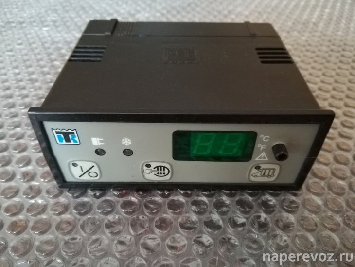
КНОПКИ И ИНДИКАТОРЫ УПРАВЛЕНИЯ
00 Световой индикатор включения; [2] Кнопка включения/выключения; [3) Световой индикатор заданной температуры; [4] Световой индикатор перегрузки по переменному току; [5] Световой индикатор работы установки; [б] Дисплей показаний температуры;0Световой индикатор показания температуры по Цельсию; [8]Световой индикатор показания температуры по Фаренгейту.
Руководство пользователя Thermo King Старых моделей серии V
Руководство пользователя Thermo King Старых моделей серии V
РАБОТА В РЕЖИМЕ ОТТАИВАНИЯ
РУЧНОЕ ВКЛЮЧЕНИЕ РЕЖИМА ОТГАИВАНИЯ*)
При нажатии кнопка ручного включения запускает режим оттаивания, если температура испарителя ниже 2°С или 35°F, при этом светодиод оттаивания должен включиться.
Установка будет работать в режиме охлаждения автоматически, когда цикл оттаивания закончится.
Руководство пользователя Direct Smart Reefer Thermo King Серии V
Руководство пользователя Direct Smart Reefer Thermo King Серии V
Установки с приводом от двигателя автомобиля и контроллером Direct Smart Reefer Руководство по эксплуатации B-100, V-100, V-200, V-300, V-400, V-500, V-700
РУССКИЙ содержание
Руководство оператора пульта управления ThermoGuard uP-T Smart Reefer
Руководство оператораThermoGuard TG-VI
Руководство оператораThermoGuard TG-VI
РАЗДЕЛ I
ПРАВИЛА БЕЗОПАСНОЙ ЭКСПЛУАТАЦИИ
Правила безопасности I-I
Общие правила I-I
Автоматический запуск/остановка I-I
Руководство пользователя Smart Reefer2
Руководство пользователя Smart Reefer2
ФУНКЦИИ ПУЛЬТА УПРАВЛЕНИЯ HMI
Пульт управления HMI (Human/Machine Interface) подключен к контроллеру и служит для управления агрегатом и отображения информации . Пульт HMI и контроллер соединены шиной CAN (Controller Area Network) . HMI также включает в себя регистратор данных о температуре груза Cargo Watch . Он расположен на дверце блока управления
Руководство оператора ThermoGuard Spectrum Multi-Temp
Раздел 1 — Информация по техникебезопасности SPECTRUM
Общие правила………………………………………………………………………………………………………………….. 1-1
Автоматический пуск и останов………………………………………………………………………………………… 1-1
Руководство пользователя SLX
SLX-100, 200 и 400 с контроллером SR-2
Введение
Общие сведения………………………………………………………………………………………………………………………………………………………………………….. 4
СЛУЖБА Thermo Assistance…………………………………………………………………………………………………………………………………………………………. 4
Коды ошибок Thermo King
Расшифровка кодов ошибок Thermo King (Термо Кинг)
Инструкции по эксплуатации органов управления Thermo King
Полезная информация о Thermo King
- Manuals
- Brands
- Thermo King Manuals
- Refrigerator
- MD-MT
- Operator’s manual
-
Bookmarks
Quick Links
MD-MT
w/TK 3.74
TK 51703-1-MM (Rev. 0, 08/02)
Copyright© 1999 Thermo King Corp., Minneapolis, MN, USA.
Printed in USA.
Related Manuals for Thermo King MD-MT
Summary of Contents for Thermo King MD-MT
-
Page 1
MD-MT w/TK 3.74 TK 51703-1-MM (Rev. 0, 08/02) Copyright© 1999 Thermo King Corp., Minneapolis, MN, USA. Printed in USA. -
Page 2
If further information is required, Thermo King Corporation should be consulted. Sale of product shown in this manual is subject to Thermo King’s terms and conditions including, but not limited to, the Thermo King Limited Express Warranty. Such terms and conditions are available upon request. -
Page 3
Ester compressor oil in tightly sealed containers. If Polyol Ester oil becomes contaminated with moisture or standard oils, dispose of properly–DO NOT USE. When servicing Thermo King R-404A unit, use only those service tools certified for and dedicated to R-404A refrigerant and Polyol Ester compressor oils. -
Page 5
Table of Contents List of Figures …………….11 Safety Precautions . -
Page 6
Table of Contents Operating Instructions (continued) Starting the Unit—Electric Operation …………56 Starting Zone 2 Evaporator . -
Page 7
Engine Mounts for MD-MT Units …….. -
Page 8
Table of Contents Refrigeration Service Operations (continued) High Pressure Relief Valve …………..120 Removal . -
Page 9
Table of Contents Electric Standby Diagnosis …………. . 143 Refrigeration Diagnosis . -
Page 10
Table of Contents… -
Page 11
List of Figures Figure 1: Typical Compartment Configurations ……….25 Figure 2: Spectrum Remote Evaporator . -
Page 12
List of Figures Figure 59: High Pressure Cutout Manifold ……….. . 109 Figure 60: Set-up and Test Evacuation Equipment . -
Page 13
Safety Precautions General Practices Auto Start/Stop 1. Always wear goggles or safety glasses. CAUTION: The unit may start Refrigerant liquid, refrigeration oil, and automatically and at any time when the battery acid can permanently damage the eyes. unit On/Off switch is in the On position. 2. -
Page 14
Safety Precautions Refrigeration Oil The following procedures must be rigidly adhered to when servicing units to avoid microprocessor Observe the following precautions when working damage or destruction. with or around synthetic or polyol ester refrigerant 1. Disconnect all power to the unit. oil: 2. -
Page 15
Safety Precautions Welding of Units or Truck Bodies Precautions When electric welding is to be performed on any 1. Be certain the Unit On/Off switch is turned portion of the temperature control unit, truck or Off before connecting or disconnecting the truck chassis when the temperature control unit is standby power plug. -
Page 16
Safety Precautions If the victim must be removed from a live circuit, pull the victim off with a non-conductive material. Use the victim’s coat, a rope, wood, or loop your belt around the victim’s leg or arm and pull the victim off. -
Page 17
Specifications Engine—TK 3.74 Engine TK 3.74 Fuel Type No. 2 Diesel fuel under normal conditions No. 1 Diesel fuel is acceptable cold weather fuel Oil Capacity: Crankcase & Oil Filter 9 quarts (8.6 liters) w/Bypass Oil Filter 10 quarts (9.6 liters) Fill to full mark on dipstick Oil Type* API Type CF-4 or CG-4 or better multigrade oil… -
Page 18
** Thermo King synthetic oil is compatible with petroleum lubricants so there is no danger if accidental mixing occurs or if an emergency required addition of petroleum oil. Mixing is not recommended, however, since it will dilute the superior… -
Page 19
Specifications R-404A Refrigeration System Compressor Model Thermo King X214 Refrigerant Charge 11.5 lb. (5.2 kg) R-404A Compressor Oil Charge 66 oz. (1.95 liters)* Compressor Oil Type Solest 35 TK No. 203-413 (Ester base) required Suction Pressure Regulator Setting 18 psig (124 kPa) -
Page 20
Specifications Belt Tension Tension No. on TK Gauge 204-427 New Belt Field Reset Engine/Compressor 75 ± 3 70 ± 3 Compressor/Jackshaft (Electric Motor) 72 ± 3 67 ± 3 Compressor/Evaporator Fan/Alternator 55 ± 5 50 ± 5 Water Pump 50 ± 5 50 ±… -
Page 21
Specifications Electrical Components Current Draw (Amps) Resistance— at 12.5 Vdc (Ohms) Glow Plug 7 to 8.3 1.5 ± 0.15 Fuel Solenoid: Pull In 18 to 36 0.3 to 0.7 Hold In 0.49 to 0.6 22 to 26 High Speed Solenoid Condenser Inlet Solenoid (15 watt) 10.4 Receiver Tank Pressure Solenoid (15 watt) -
Page 22
Specifications… -
Page 23
Maintenance Inspection Schedule A closely followed maintenance program will The schedule covers units with conventional help to keep your Thermo King unit in top coolant and units with ELC. operating condition. The following general schedule is provided to assist in monitoring that maintenance. -
Page 24
Maintenance Inspection Schedule 1,200 Annual/ Inspect/Service These Items trip Hours Hours 3,000 NOTE: The 1,200 hour maintenance interval may be extended to Hours 2,000 hours or 1 year (whichever occurs first) when equipped with EMI fuel filter and EMI bypass oil filter. Electrical •… -
Page 25
10.7 continuous horsepower condenser. (7.98 kW) at 2400 RPM. A centrifugal clutch The MD-MT operates under the control of a mounted on the engine and belt drive system TG-V microprocessor controller. The In-Cab transfer power to the compressor, water pump, Dual-Temp Controller provides safe, convenient condenser fan and alternator. -
Page 26
Unit Description The MD-MT will operate in one of the following A Spectrum remote evaporator is located in modes depending on the air temperature in the each compartment and can provide separate truck’s cargo compartment as sensed by the temperature controlled areas. -
Page 27
Unit Description Unit Operation • The flow of refrigerant through the system is controlled by the solenoid valves and the Several operating characteristics of the system check valves. during engine operation are: • The solenoid circuits are switched by the •… -
Page 28
Unit Description Reading Mode of Operation Charts The Mode of Operation Charts use the status of the 1K and 2K relays (or the R1K and R2K relays) to show the thermostat demand: D = De-energized (0 volts) E = Energized (12 volts) High Speed Cool—1K = D and 2K = E Low Speed Cool—1K = D and 2K = D Low Speed Heat—1K = E and 2K = D… -
Page 29
Unit Description Mode of Operation Charts Engine Operation* Two Compartment (with Door Sentry II) Thermostat Relays F Door R Door Solenoids Fans Fans Speed Zone 1 Zone 2 F-COOL CLOSED CLOSED HIGH R-COOL F-COOL CLOSED CLOSED R-COOL F-HEAT CLOSED CLOSED R-HEAT F-HEAT CLOSED CLOSED HIGH… -
Page 30
Unit Description Engine Operation Single Compartment (with Door Sentry II) (One Large Compartment Using Both Evaporators)* Thermostat Relays F Door R Door Solenoids Fans Fans Speed Zone 1 Zone 2 F-COOL CLOSED CLOSED HIGH R-COOL F-COOL CLOSED CLOSED R-COOL F-HEAT CLOSED CLOSED R-HEAT F-HEAT… -
Page 31
Unit Description Electric Operation* Two Compartment (with Door Sentry II) Thermostat Relays F Door R Door Elec. Solenoids Fans Fans Motor Zone 1 Zone 2 F-COOL CLOSED CLOSED D D D COOL COOL R-COOL F-COOL CLOSED CLOSED D D D COOL COOL R-COOL… -
Page 32
Unit Description Electric Operation Single Compartment (with Door Sentry II) (One Large Compartment Using Both Evaporators)* Thermostat Relays F Door R Door Elec. Solenoids Fans Fans Motor Zone 1 Zone 2 F-COOL CLOSED CLOSED D D E COOL COOL R-COOL F-COOL CLOSED CLOSED D D E… -
Page 33
Unit Description Zone 1 Suction Line Check Valve (SLCV)— Zone 1 Cool and Zone 2 Cool Open High pressure refrigerant vapor leaves the Zone 1 Suction Line Solenoid (SLS)—Open compressor and flows through the open CIS to the condenser where the refrigerant condenses into Zone 1 Hot Gas Solenoid (HGS)—Closed high pressure liquid. -
Page 34
Unit Description Zone 1 Suction Line Solenoid (SLS)—Open Zone 1 Cool and Zone 2 Heat Zone 1 Hot Gas Solenoid (HGS)—Closed The CIS is closed so high pressure refrigerant vapor leaves the compressor and flows through Zone 2 Evaporator the Zone 2 hot gas line and the open RHGS into the Zone 2 evaporator. -
Page 35
Unit Description At setpoints above 15 F Operating Modes Zone 2 Evaporator: (-9.4 C), the Zone 2 evaporator operates in the High Speed Heat is normally locked out at following modes. setpoints below 15 F (-9.4 C). • Cool Engine, Continuous Run—Two •… -
Page 36
Unit Description At setpoints above 15 F Engine, Continuous Run—Single Zone 2 Evaporator: (-9.4 C), the Zone 2 evaporator operates in the Compartment Operation following modes. At setpoints above 15 F Zone 1 Evaporator: (-9.4 C), the Zone 1 evaporator operates in the •… -
Page 37
Unit Description CYCLE-SENTRY Operation Units that are equipped with the CYCLE-SENTRY option will shut down when both evaporators are in Null. The unit starts when either thermostat calls for high speed or when Defrost is initiated in either evaporator. Features of the CYCLE-SENTRY system are: •… -
Page 38
Electric Operation Defrost Operation During electric operation, the electric motor will As the MD-MT is operated to cool the cargo box, stop when both evaporators are in Null. The frost will gradually build up on the evaporator electric motor will not start until one of the coils. -
Page 39
Unit Description Three methods of Defrost initiation are available: Microprocessor Controller TG-V: Microprocessor Controller is programmed to automatically initiate a Defrost cycle every 4 hours during pulldown until return air temperature is in-range (between approximately 7 degrees above and 7 degrees below setpoint). The Air Switch automatically places Air Switch: the unit into Defrost when the frost accumulation… -
Page 40
Unit Description Design Features Unit Model Unit Model Unit Model Unit Model MD-MT 50 MD-MT 50 MD-MT 30 MD-MT 30 (920004) (920006) (920003) (920005) TK 3.74 Diesel Engine • • • • X214 Compressor with Solest 35 Compressor • •… -
Page 41
Unit Description Unit Photographs ARD024 Figure 12: Roadside View ARD025 Figure 13: Curbside View… -
Page 42
Unit Description AMA01 Engine Oil Dipstick Coolant Tank Compressor Oil Sight Glass Receiver Tank Sight Glass Electric Motor Reset (Model 50) Electric Motor (Model 50) Figure 14: Top View… -
Page 43
Unit Description ARD041 Figure 15: Engine Side Door Open… -
Page 44
Unit Description 1. One Temp/Two Temp Switch 6. Preheat/Start Switch 2. Auto Start/Stop — Continuous Run Switch 7. Run Hourmeter (Optional on Model 50) 3. Stop Start Light (Optional) 8. Electric Operation Hourmeter (Optional on Model 50) 4. Engine Reset 9. -
Page 45
Unit Description AEA2127 Temperature Display (Zone 1) Temperature Display (Zone 2) Power Cord Indicator Light (Model 50) EFROST 10. Z EFROST NTER 12. W ELECT HISPER Figure 17: TG-V In-Cab Controller for Multi-Temp Compartment Units… -
Page 46
Unit Description aea04 NOTE: Apply Thread Sealant When Installing High Pressure Cutout Oil Seal (Location Not Shown) Crankshaft Discharge Port Cylinder Head Figure 18: X214 Compressor… -
Page 47
Unit Description aea05 Cylinder Head Oil Pump Cover Crankshaft Pressure Regulator Assembly Oil Fill Plug Oil Pump Gauge Access Serial Number 10. Suction Port Sight Glass Suction Valve Adapter Oil Drain Plug Figure 19: X214 Compressor… -
Page 48
Unit Description… -
Page 49
Operating Instructions Unit Controls • The Microprocessor Controller calls for heating or cooling. TG-V Multi-Temp Control Box • Manual Defrost initiated. WARNING: Do not operate the unit until • Engine block temperature drops below you are completely familiar with the 30F (-1 C). -
Page 50
Operating Instructions TG-V In-Cab Controller for Other situations which may cause the engine reset Multi-Compartment Units to open are: • Engine runs out of fuel. WARNING: Do not operate the TG-V until you are completely familiar with the • On/Off switch is left on accidentally without meaning of each display symbol, and the the engine being started. -
Page 51
Operating Instructions Used to select the various displays Key: During the normal operation, the standard display ELECT which can appear on the screen. is on the screen. Used to increase setpoint temperature Key: Return Air Temperature is factory standard when the setpoint symbol is on the screen. display setting (can be changed). -
Page 52
Operating Instructions Other Controls Unit Protection Devices A temperature Defrost Termination Switches: A thermal type manual reset Engine Reset Switch: sensitive switch is mounted on each evaporator switch protects the engine. The reset switch coil. It is used to control Defrost. The switch contains a heater coil that is attached to a sensor closes when the evaporator temperature drops to switch in the engine oil system, engine coolant… -
Page 53
Operating Instructions The engine low The engine oil level should be at the Engine Low Oil Pressure Cutout: Engine Oil: oil pressure cutout is a pressure sensitive switch FULL mark on the dipstick. Never overfill. located in the engine oiling system. This switch Check coolant level gauge for the correct Coolant: will trip the Engine Reset and stop the engine if… -
Page 54
CYCLE-SENTRY Equipped Units thermostat demand. The unit runs The Thermo King CYCLE-SENTRY system is continuously until it is turned off manually. designed to save refrigeration costs. The savings The start sequence, once initiated, is the vary with the commodity, ambient temperatures same for both systems. -
Page 55
Operating Instructions Examples of Products Normally CYCLE-SENTRY Operation Acceptable for CYCLE-SENTRY Operation With the selector switch placed in the • Frozen foods (in adequately insulated trailers) CYCLE-SENTRY position, the CYCLE-SENTRY system shuts down the unit • Boxed or processed meats when the compartment temperature reaches the •… -
Page 56
Operating Instructions NOTE: A unit that is equipped with 7. At the end of the preheat period, the engine CYCLE-SENTRY should be manually started if will begin cranking. The glow plugs remain it has been turned off long enough for the engine energized during the cranking period. -
Page 57
Starting Zone 2 Evaporator 4. Products should be pre-cooled before loading. 1. Start the condensing unit Zone 2 will Thermo King units are designed to maintain automatically be on. loads at the temperature at which they were loaded. Transport refrigeration units are not 2. -
Page 58
Operating Instructions Post Trip Checks 1. Wash the unit. 2. Check for leaks. 3. Check for loose or missing hardware. 4. Check for physical damage to the unit. -
Page 59
Thermo King P/N NOTE: Units manufactured with 204-615 (FLUKE 23) digital multimeter and a CYCLE-SENTRY and alternators with integral Thermo King P/N 204-613 amp clamp or an regulators MUST use replacement alternators equivalent. with integral regulators. -
Page 60
Electrical Maintenance NOTE: All voltage readings should be taken b. If there is low or no output, the alternator between the negative battery terminal, or a good is probably faulty. However, the following chassis ground, and the terminals indicated, items are potential causes for not charging: unless stated otherwise. -
Page 61
Electrical Maintenance Glow Plugs Conditions that cause the reset switch to trip: • Engine coolant (water) temperature over Glow plugs heat the combustion chamber to aid in 220 F (104 C). quick starting. The glow plugs are energized when the Preheat/Start switch is held on the Preheat or •… -
Page 62
Electrical Maintenance Low Oil Pressure Switch (LOP) If the circuit breaker opens, check the unit for a grounded wire or a grounded condition in a relay The engine oil pressure should rise immediately or solenoid. after the engine is started. The LOP will trip the reset switch and stop the engine if the oil pressure Evaporator Circuit Breaker drops below 10 ±… -
Page 63
Electrical Maintenance Unloading Timer (EUT) 6. Place the On/Off switches in the On position and press the key. The unloading timer energizes the unloading relay 7. Check for battery voltage at the 7KB wire in (EUR) for approximately 20 seconds when the the main wire harness. -
Page 64
Electrical Maintenance Defrost System Zone 1 Evaporator Defrost Cycle Diesel Operation CAUTION: This unit is equipped with The Defrost cycle can be initiated with the ANUAL Auto Start. It will start automatically if the key, by the air switch, or by the defrost EFROST key is pressed while the On/Off timer in the TG-V Controller when the defrost… -
Page 65
Electrical Maintenance Zone 1 Evaporator Defrost Cycle Zone 1 Evaporator Does Not Defrost Checkout Procedure 1. Check the evaporator temperature: Make sure the evaporator temperature is CAUTION: This unit is equipped with actually below 42 F (6 C) if the unit will not Auto Start. -
Page 66
Electrical Maintenance Zone 1 Evaporator Sticks In Defrost 1. Check the evaporator temperature: Indefinitely Be sure the evaporator temperature is actually If the unit remains stuck in Defrost indefinitely, above 52 F (11 C) if the unit will not terminate check the defrost relay, the 11 circuit and the Defrost. -
Page 67
Electrical Maintenance Zone 2 Evaporator Does Not Defrost Initiating the Defrost cycle energizes the Zone 2 defrost relays, RD and RDR4. When RD is 1. Check the evaporator temperature: energized, it energizes the RHGS circuit, which energizes the RHGS and the 26 circuit. The 26 Make sure the evaporator temperature is circuit energizes the CIS (and the RTPS and PV actually below 42 F (6 C) if the unit will not… -
Page 68
Electrical Maintenance Zone 2 Defrost Relay (RD) Zone 1 Fan Relay (FR) Zone 2 Fan Relay (RFR) Zone 1 Defrost Relay (DR) Figure 23: Defrost Relay Locations Zone 2 Evaporator Will Not Terminate 1. Check the Zone 2 defrost relays: Defrost If the unit remains on Defrost indefinitely, If the defrost termination switch does not… -
Page 69
Electrical Maintenance Zone 2 Evaporator Continuously Fails to Defrost System Components Terminate Defrost In Less than 45 Minutes Defrost Termination Switches If the unit continually fails to complete the Defrost cycle in less than 45 minutes, and cycles Each electronic defrost termination switch uses between Cool and Defrost, check the evaporator solid state components to control the Defrost coil temperature, RHGS, CIS, PV, RTPS, RTPC,… -
Page 70
Electrical Maintenance 2. Connect the negative lead of the switch to the 1. Remove plastic sensing tubing from both sides negative battery terminal. of the air switch. 3. Raise the temperature of the defrost 2. Disconnect one wire at the switch terminal. termination switch above 52 F (11 C). -
Page 71
Electrical Maintenance AGA271 Adjustment Screw Squeeze Bulb (P/N 204-494) Continuity Tester Pressure in Inches of Water (P/N 204-442) Figure 25: Air Switch Testing and Adjustment Measuring Evaporator Coil Pressure 4. Run the unit in High Speed Cool and measure Differential the evaporator coil pressure differential. -
Page 72
Diagnosis Manual for all operation and diagnosis is connected to the +12 Fan circuit, the Fan SC procedures. The MD-MT is not presently included circuit, and ground. The voltage on the Fan SC in that manual but the system is similar. -
Page 73
Electrical Maintenance Multi-Temp Relay Board The multi-temp relay board is located inside the control box. The thermostat relays and the associated control relays are located on the multi-temp relay board. The component locations are shown in the following illustration. AEA623 Zone 2 Heat/Cool Relay (R1K) 6. -
Page 74
Electrical Maintenance AC Components The In-Cab TG-V functions similarly to the standard unit mounted TG-V. However, the In-Cab TG-V Controller also has the following CAUTION: The unit uses high voltage additional features: alternating current (ac) during electric operation. Lethal voltage potentials can •… -
Page 75
Electrical Maintenance Field Test Procedure for 4. Press the key to display the setpoint(s) ELECT Multi-Temperature In-Cab TG-V and adjust the setpoint(s) to 80 F (27 C). Both Controllers setpoints must be adjusted to 80 F (27 C) to properly test the multi-temperature controller. Use tester P/N 204-831. -
Page 76
Electrical Maintenance Connector Pins for Multi-Temp In-Cab TG-V Pin # Circuit Code Harness Wire Color Code Circuit Description WHT/BLK/RED Remote Unit (Zone 2) On/Off Relay WHT/VOIL Remote Unit (Zone 2) High Speed Relay WHT/ORG On/Off Switch BLUE Not Used YELLOW Remote Unit (Zone 2) Heat Relay WHT/BLK/ORG On/Off Switch… -
Page 77
Electrical Maintenance Door Sentry II Opening Both Zone 1 and Zone 2 Doors Door Sentry II is a factory option that is designed Because power to operate the coils of relays XK1, to improve temperature control when the doors XK2 XK3 and XK4 is removed when the Zone 2 are opened during delivery. -
Page 78
Electrical Maintenance Door Sentry-II Operation Modes Zone 1 Zone 2 Zone 1 Door Open Zone 2 Door Open Both Doors Open HS Cool Cool Unit goes to low speed, All power to Zone 2 unit Zone 1 unit ERC disabled. damper solenoid control circuits and Zone 1 unit runs normal. -
Page 79
NOTE: Units equipped with the EMI 2000 Maintenance consists of replacing the switch. package do require regular inspection in accordance with Thermo King’s maintenance Engine Oil Change recommendations. The engine oil should be changed according to the NOTE: The new EMI 2000 oil filters and new “Maintenance Inspection Schedule”. -
Page 80
25 in. (635 mm) of vacuum, or at 2,000 hours, or 1 year, whichever occurs first. It cannot be interchanged with air filter elements used on previous Thermo King truck units. Spin-on Oil Filter Pressure Valve Nut… -
Page 81
Engine Maintenance Oil Bath Type A heavy duty, oil bath air cleaner filters all of the air entering the engine. Excessive restriction of the air intake system reduces the flow of air to the engine affecting horsepower output, fuel consumption and engine life. The air cleaner removes abrasive material from the air entering the engine. -
Page 82
Engine Maintenance Engine Cooling System from the side of the radiator (large header), circulates it through the cylinder block and head, The engine employs a closed, circulating type, then back to the radiator. A thermostat mounted in pressurized cooling system. Correct engine the water outlet from the cylinder head to the temperatures are controlled and maintained by a radiator automatically maintains coolant… -
Page 83
To upgrade new production engines for ELC use, The following are the Extended Life Coolants all water pump seal bellows were changed from currently approved by Thermo King for use in NBR to HNBR elastomer, and the o-rings ELC units for five years or 12,000 hours: upgraded from NBR to EPDM elastomer. -
Page 84
Engine Maintenance Antifreeze Maintenance Procedures As with all equipment containing antifreeze, periodic inspection on a regular basis is required to verify the condition of the antifreeze. Inhibitors become worn out and must be replaced by changing the antifreeze. Change green or blue-green engine coolant every two years. -
Page 85
Engine Maintenance Bleeding Cooling System After filling the radiator, run the unit up to operating temperature to check for overheating and coolant level and allow the air to be purged for a few minutes. CAUTION: Do not remove the radiator cap while the engine is hot. -
Page 86
Engine Maintenance Engine Fuel System The fuel system used on the Thermo King TK 3.74 diesel is a high pressure system used in conjunction with a prechamber. The components of the fuel system are: • Fuel tank (may be the truck fuel tank) •… -
Page 87
Engine Maintenance Fuel Pump Bypass Oil Filter To Fuel Tank Oil Pressure Switch Oil Filter Oil Pressure Gauge (Optional) Fuel Filter Diesel Fuel Heater (Optional) Figure 41: Fuel and Oil System Components… -
Page 88
Engine Maintenance Thermo King recommends that any major 3. Tighten the bleeder screw on the injection injection pump or nozzle repairs be done by a pump when clear flow of fuel appears. quality diesel injection service specialty shop. The NOTE: At initial start-up, open the bleeder… -
Page 89
Engine Maintenance Electric Fuel Pump If pump does not operate, check for: • Ground to the frame of the TK unit Operation • Clean and tighten electrical connections The electric fuel pump must be mounted next to • The pump voltage and polarity. It must be the the fuel tank. -
Page 90
Engine Maintenance Integral Fuel Solenoid When the fuel solenoid is energized, current is applied to the coil creating an electro-magnetic The fuel stop solenoid is located on the end of the field, which pulls the When in the “pulled-in” fuel injection pump. position, the plunger releases tension on the governor linkage. -
Page 91
Engine Maintenance The size of the capacitor has been changed to increase the pull-in time from 1 second to 2 seconds. This minimizes the chance that the pull-in coil would fail to open the fuel valve. The integral fuel solenoid contains two coils: the pull-in coil, and the hold-in coil. -
Page 92
Engine Maintenance Troubleshooting the Integral Fuel 5. Check the CH pin in the fuel solenoid wire Solenoid System connector for continuity to a good chassis ground. NOTE: The fuel solenoid pull-in coil will require 30 to 40 amps to turn on the fuel. The a. -
Page 93
Engine Maintenance b. Momentarily energize the pull-in coil by 12. Check the voltage on the 2B circuit at the 30 placing a jumper between the 8DP pin in terminal in the fuel solenoid relay socket. the fuel solenoid and the 2 terminal at the a. -
Page 94
Engine Maintenance Fuel Stop Solenoid Replacement NOTE: The fuel stop solenoid must be energized when it is being installed. If it is 1. Disconnect the 20 wire from the reset switch not, the plunger and the linkage may not line to prevent the reset switch from tripping. -
Page 95
Turn the screw out engine fully warmed up. to decrease the engine speed. The MD-MT has one solenoid to control the high 5. Set the engine speed at 1625 ± 25 RPM and speed function. The speed of the engine should be tighten the jam nut. -
Page 96
Engine Maintenance 2. Remove the injection line from the number 1 CAUTION: The cylinders on the engine injector and the injection pump. Remove the are numbered from the flywheel end to the delivery valve holder, delivery valve and water pump end. The number 1 cylinder is spring. -
Page 97
Engine Maintenance 10. When the injection pump has been correctly 12. Reinstall the delivery valve and spring. timed to the engine, remove the pump and put Torque the delivery valve holder to 30 ft-lb a light coat of silicone gasket sealer on the (41 N•m). -
Page 98
CAUTION: Make sure the fuel rack is off procedures. California service technicians should to prevent the engine from starting. see your local Thermo King dealer for recent bulletins. a. Turn the engine so number 1 cylinder is on compression with piston to TDC. Both push rods should turn freely. -
Page 99
Engine Maintenance Engine Mounts for MD-MT Units The engine mounting system contains three vibration mounts and two snubber mounts. 0.020 Air Gap Between Lower Snubber and Vibration Mount (91-2276) Engine Bracket When Assembled (Snubbers Only) Snubber Mount (99-4820) Snubber Bracket (91-3201) -
Page 100
(or set) the belt tension. working on any part of the unit. a. The belt tension should be set at a reading of 70 ± 3 on the Thermo King Belt Tension Gauge. b. The belt should deflect 1/2 in. (13 mm) at the center of the longest (lower) span. -
Page 101
The engine/compressor belt tension should be set enough to allow the sprocket to rotate at a reading of 70 ± 3 on the Thermo King Belt freely. If not, the reading on the torque Tension Gauge. -
Page 102
50 ± 5 deflection of the compressor/alternator belts on the Thermo King Belt Tension Gauge. If the Thermo King Belt Tension Gauge is not used, the belt should deflect 1/2 in. (13 mm) at the center of the longest span. -
Page 103
(See evacuation should always be practiced. attached tool list and evacuation procedures.) See the diagram of the Thermo King Evacuation The primary objective of evacuation is to bring Station and note the location of the valves. -
Page 104
Refrigeration Maintenance AGA654 Two Stage Vacuum Pump Thermistor To 110 Vac Power Calibration Standard Vacuum or Micron Gauge Figure 55: Evacuation Station… -
Page 105
Refrigeration Maintenance 100 Microns 500 Microns 1000 Microns 2500 Microns 5000 Microns 20,000 Microns Atmospheric Pressure Calibration Adjustment Screw Example: Meter needle shown at calibration position when Calibration Standard specifies 0.15 mm Hg. Figure 56: Vacuum Gauge… -
Page 106
Refrigeration Maintenance Refrigerant Charge Testing the Refrigerant Charge with a Loaded Truck Testing the Refrigerant Charge with 1. Install a gauge manifold (optional). an Empty Truck 2. Run both evaporators on the Cool cycle. If the unit has an insufficient charge of refrigerant, 3. -
Page 107
Refrigeration Maintenance Moisture Indicating Sight 6. By the time the discharge pressure decreases approximately 50 psig (345 kPa), the ball in Glasses the receiver tank sight glass should begin to The receiver tank is equipped with a moisture move and the liquid level should decline. indicating sight glass. -
Page 108
Refrigeration Maintenance Refrigerant Leaks Checking Compressor Oil Use a reliable leak detector (e.g., electronic The compressor oil should be checked when there detector) to leak test the refrigeration system. is evidence of oil loss (oil leaks) or when Inspect for signs of oil leakage which is the first components in the refrigeration system have been sign of a leak in the refrigeration system. -
Page 109
Refrigeration Maintenance High Pressure Cutout (HPCO) To check compressor oil level with an ambient air Run the unit temperature below 50 F (10 C): The high pressure cutout is located on the through a complete Defrost cycle. After compressor cylinder head. If the discharge completing the Defrost cycle, run the unit on Cool pressure rises above 450 psig (3103 kPa) on for ten minutes. -
Page 110
Refrigeration Maintenance Evacuating and Charging 3. Raise the discharge pressure of the compressor by blocking the condenser coil air Procedures flow by covering the roadside condenser grille with a piece of cardboard. Set-up Electrical Controls NOTE: The discharge pressure should never 1. -
Page 111
Refrigeration Maintenance 5. Once a vacuum of 100 microns has been 7. If the pressure rises above 1500 microns in 5 reached, close the vacuum valve at the minutes, check all the hoses and connections vacuum pump and stop the pump. for leaks and repeat steps 3 through 6. -
Page 112
Refrigeration Maintenance Unit Evacuation 8. After the hour of additional evacuation time, open the suction service valve. The vacuum NOTE: The electrical system must be energized gauge reading will rise. Continue to evacuate throughout this procedure. the system back down to 500 microns. When 1. -
Page 113
Refrigeration Maintenance AEA2088 Vacuum Gauge Vacuum Valve Thermistor Leave Hand Valve Closed for First 5 Minutes of Evacuation Figure 61: Unit Evacuation… -
Page 114
Refrigeration Maintenance Unit Charging 5. Connect the HGSA wire and the RHGS wire to the relay board. Connect the condenser inlet NOTE: The electrical system must be energized solenoid wires (2 pin connector) to the main throughout this procedure. wire harness. Replace the front and rear fan 1. -
Page 115
Refrigeration Maintenance AEA2088 Refrigerant Scale Evacuate or Purge Closed Closed Open for Liquid; Back Seat for Vapor Back Seat for Liquid; Open for Vapor Figure 62: Unit Charging… -
Page 116
Refrigeration Maintenance Remove Evacuation Hoses 3. Back seat the suction service valve. 1. Run the Zone 1 and Zone 2 units in High 4. Remove the hoses from the receiver outlet and Speed Cool with the receiver outlet and discharge service valves. discharge service valves back seated. -
Page 117
Refrigeration Service Operations NOTE: It is generally good practice to replace 3. Prepare to perform service on the unit’s low the filter-drier whenever the high side is opened side by equalizing the high side and low side or when the low side is opened for an extended pressures. -
Page 118
Refrigeration Service Operations Compressor 5. Back seat the suction and discharge service valves. Removal 6. Operate the unit at least 30 minutes and then inspect the oil level in the compressor. Add or 1. Pump down the compressor and equalize the remove oil if necessary. -
Page 119
Refrigeration Service Operations Drier Whenever the two-piece pulley is removed from any type of unit service, anti-seize lubricant should be applied to the outside of the tapered Removal surface on the pulley bushing. Use one of the 1. Pump down the low side and equalize the following recommended anti-seize lubricants: pressure to slightly positive. -
Page 120
Refrigeration Service Operations Accumulator 4. If no leaks are found, open the refrigeration valves and place the unit in operation. Removal High Pressure Relief Valve 1. Pump down the low side and equalize the pressure to slightly positive. Removal 2. Drain the engine cooling system. 1. -
Page 121
Refrigeration Service Operations Receiver Tank Removal 1. Remove the refrigerant charge. 2. Unsolder the inlet tube from the receiver tank. 3. Unsolder the drier line from the receiver tank outlet tube. 4. Unbolt the mounting hardware and remove the receiver tank from the unit. Installation 1. -
Page 122
Refrigeration Service Operations Condenser Inlet Check Valve Installation Replacement 1. Inspect the inside of the check valve body for damage or foreign particles which might Removal adhere to the seat and damage the new seat. If the body is damaged, replace the check valve. 1. -
Page 123
Refrigeration Service Operations Suction Line Check Valve and Purge Check Valve Replacement (SLCV, RSLCV, and PCV) Removal 1. Pump down the low side and equalize the pressure to slightly positive. 2. Unsolder the lines and remove the check valve. 1. Spring 3. -
Page 124
Refrigeration Service Operations Receiver Tank Pressure Purge Valve (PV) Solenoid Valve (RTPS) NOTE: Valves that have nylon seats must be disassembled before soldering. Removal Removal 1. Pump down the low side and equalize the pressure in the high side to slightly positive. 1. -
Page 125
Compressor Oil The pressure temperature relationship of R-404A Thermo King Corporation has chosen to use a is similar to that of R-502. The capacities of this compressor oil called Polyol Ester (POE)—also new refrigerant is similar for box temperatures called ester based oil. -
Page 126
Dedicated Equipment Gauge manifolds and manifold hoses used with other Thermo King refrigerants maybe used but CAUTION: Equipment that has been used extreme care should be taken to prevent with other refrigerants MUST NOT be contamination of the R-404A systems with other used with R-404A refrigerants. -
Page 127
Refrigeration Service Operations Stabilizer Bracket ORS Adapter Bracket Screw 12. 3/8 O-ring Flatwasher 13. Compressor Inlet Tube Lockwasher 14. Filter Assembly 15. 1/4 O-ring Cylinder Head Stud 16. 3/8 O-ring Bracket Nut 17. Clamp Flatwasher 18. Compressor Outlet Tube Sealing Washer 19. -
Page 128
Refrigeration Service Operations… -
Page 129
Hilliard Clutch Maintenance Large Truck Unit Centrifugal 107-204. Centrifugal clutch P/N 107-291 has three belt grooves and its engagement speed is Clutch Change (P/N 107-291) 600 ± 100 RPM. When this clutch is installed on a Beginning in the second quarter of 2000 most unit equipped with a two groove belt, the belt large truck units are equipped with centrifugal should be placed in the two grooves nearest to the… -
Page 130
Hilliard Clutch Maintenance aea558 (3 belt grooves) Screw 10. Grease Seal Washer Roller Bearing Inner Race Snap-Ring 12. Pulley Housing Ball Bearing 13. Elastic Stop Nuts (6) Large & Small Spacers 14. Connector Link (6) Rolling Bearing 15. Spring (6) Lockwasher (12) 16. -
Page 131
Hilliard Clutch Maintenance Clutch Maintenance Using an inspection mirror, inspect the clutch every 1000 hours of operation or yearly, whichever occurs first. If clutch removal is necessary, clean the shoes and drum, regrease bearings or replace if they are worn. Inspect anchor bushings, shoe lining and springs for wear and replace if necessary. -
Page 132
Hilliard Clutch Maintenance 8. Remove inner race of roller bearing from the 2. Remove the inner race from the roller bearing, housing shaft. apply a small amount of Loctite #270 to race I.D. and press onto the housing shaft, seating NOTE: This race was Loctited and pressed against the step. -
Page 133
Hilliard Clutch Maintenance 14. Place the hub and shoe assembly into the housing and place flatwasher over the bearing. 15. Apply Loctite #680 to 3/8-16×1 screw and install through washer into housing shaft. The housing and hub will be drawn together to the proper relative position as the screw is tightened. -
Page 134
Hilliard Clutch Maintenance… -
Page 135
Structural Maintenance Unit and Engine Mounting Bolts Fan Location Periodically check and tighten all unit and engine When mounting the fan and hub assembly on the mounting bolts. Torque the unit mounting motor or jackshaft, position the assembly in the bolts to 60 ft-lb (81.3 N•m). -
Page 136
Structural Maintenance… -
Page 137
Mechanical Diagnosis Condition Possible Cause Remedy Unit switched On—indicator Batteries discharged Charge or replace batteries lights do not come on Reset switch tripped Check engine oil, coolant level, and CYCLE-SENTRY system (optional). Push in reset switch button Corroded battery connections Clean and tighten Circuit breaker tripping Check for short circuit in unit wiring… -
Page 138
Mechanical Diagnosis Condition Possible Cause Remedy Engine stops after starting Air in injection pump Bleed fuel system Fuel filter obstructed Replace filter element High head pressure Eliminate cause of high head pressure Vent of fuel tank obstructed Unclog vent Reset switch trips Check engine oil, coolant level, and CYCLE-SENTRY system (optional). -
Page 139
Mechanical Diagnosis Condition Possible Cause Remedy Engine runs hot Dirty radiator Clean radiator Coolant level is low Add coolant Cooling system heavily scaled Clean cooling system Cylinder head gasket leaks Replace cylinder head gasket. Use correct gasket Faulty thermostat Check or replace the thermostat Loose or worn water pump belt Replace belt Oil pressure too low or drops… -
Page 140
Mechanical Diagnosis Engine Emits Excessive Smoke White Smoke Black Smoke Blue Smoke Fuel is not burning Excessive Fuel to Air Ratio Oil Consumption • Air or water in fuel • Type of fuel used • Poor compression • Incorrect timing •… -
Page 141
CYCLE-SENTRY Diagnosis Condition Possible Cause Test Procedure Run relay will not energize when Open 7A circuit from selector switch Test 7A circuit required to run relay Defective selector switch Test circuit from 7M or 7MA to 7A on switch in the CYCLE position Open 7M or 7MA circuits Test 7M and 7MA circuits Open diode from 77, R7C, 7C or 7X… -
Page 142
CYCLE-SENTRY Diagnosis Condition Possible Cause Test Procedure Unit cranks only after preheat has Defective engine temperature Test engine temperature thermistor occurred for approximately 6 thermistor minutes Open BL1 or BL2 wires from option Check BL1 and BL2 wires board to engine temperature thermistor Defective CSM Test or replace CSM… -
Page 143
Electric Standby Diagnosis Condition Possible Cause Remedy Unit switch On— lights do not Battery discharged Charge or replace battery come on Dirty battery terminals Clean and retighten terminals Fuse F1 blown Replace fuse F1 Unit switch On— but electric No standby power Provide power to unit;… -
Page 144
Electric Standby Diagnosis Condition Possible Cause Remedy Contact chatter Low battery voltage Check voltage condition. Check momentary voltage dip during starting—low voltage prevents magnet sealing Defective or incorrect coil Replace coil Poor contact in control circuit Check auxiliary switch contacts and overload relay contacts. -
Page 145
Refrigeration Diagnosis Possible Causes • • • • Overcharge of refrigerant • • • • • • Shortage of refrigerant • • • • • No refrigerant • Air through condenser too hot (ambient) • Air flow through condenser restricted •… -
Page 146
Refrigeration Diagnosis Possible Causes • • Expansion valve open too much • • Expansion valve closed too much • • Expansion valve needle eroded or leaking • • • Expansion valve partially closed by ice, dirt or wax • • •… -
Page 147
Refrigeration Diagnosis Possible Causes • • • • Leaky Zone 1 hot gas solenoid (HGS) • • Closed Zone 1 hot gas solenoid (HGS) • • • Leaky Zone 1 liquid line solenoid (LLS) • • • • • • Closed Zone 1 liquid line solenoid (LLS) •… -
Page 148
Refrigeration Diagnosis… -
Page 149
Remote Evaporator Specifications Refrigeration System Evaporator Coil Type Direct Expansion Refrigerant Type R404a Heat/Defrost Method Hot Gas Electrical Control System Voltage 12.5 Vdc Spectrum Evaporator Fan Motor: Horsepower 0.13 hp Fan Voltage 8 to 16 Vdc 1900 Full Load Amps 8.7 amps per motor Fuse F1-1, F1-2, F2-1, F2-2 30 amp… -
Page 150
Remote Evaporator Specifications… -
Page 151
Remote Evaporator Maintenance Inspection Schedule Every Annual / Pretrip 1,500 4,500 Inspect/Service These Items Hours Hours Electrical • • Inspect wire harness for damaged wires or connections. • • Inspect/replace fan motor brushes. Structural • • • Visually inspect unit for fluid leaks. •… -
Page 152
Remote Evaporator Maintenance Inspection Schedule… -
Page 153
Remote Evaporator Unit Description Discharge & Return Air 1. Coil Temperature Sensor, Ungraded) Terminal Board Bracket Sensor (Graded) 2. Hot Gas Solenoid 6. Variable Blower (12 V) 10. Terminal Board 3. Liquid Line Solenoid 7. Blower Housing 11. Terminal Board Markstrip Resistance Wire (3000 mm) 4. -
Page 154
Remote Evaporator Unit Description AJA984 Figure 82: Spectrum Evaporator-Front View AJA985 Figure 83: Spectrum Evaporator-Back View… -
Page 155
Remote Evaporator Unit Description Unit Features The Spectrum multi-temperature refrigeration system provides heavy duty temperature control • Direct Expansion Evaporator Coil for multiple compartment trucks. The system provides direct expansion cooling in all cargo • 12 Vdc Fan Motor compartments. •… -
Page 156
Remote Evaporator Unit Description… -
Page 157
Remote Evaporator Refrigeration Service Operations NOTE: It is generally good practice to replace 8. Test the unit to see that the expansion valve is the filter drier whenever the high side is opened properly installed. or when the low side is opened for an extended period of time. -
Page 158
Remote Evaporator Refrigeration Service Operations Solenoid Valves NOTE: Valves that have nylon seats must be disassembled before soldering. Removal 1. Pump down the low side and equalize the pressure to slightly positive. AEA648 2. Remove the access panels. 3. Remove the coil and disassemble the valve. Valve 4. -
Page 159
Remote Evaporator Structural Maintenance Unit Inspection Inspect the unit during the unit pretrip inspection and scheduled maintenance inspections for loose or broken wires or hardware, chaffed wires, compressor oil leaks, or other physical damage which might affect unit performance and require repair or replacement of parts. -
Page 160
Remote Evaporator Structural Maintenance… -
Page 161
Remote Evaporator System Diagnosis Condition Possible Cause Remedy Load temperature too high Refrigerant shortage Repair leak and recharge Setpoint too high Adjust setpoint Expansion valve plugged Clean or replace Partial obstruction in low side of Locate obstruction and repair refrigeration system Iced or dirty evaporator coil Defrost or clean evaporator coil Expansion valve open too much… -
Page 162
Remote Evaporator System Diagnosis… -
Page 163
Index AC components 74 ELC (extended life coolant) 83 accumulator 120 electric fuel pump 89 after start inspection 57 electric operation 56 air switch, specifications 19 electric standby diagnosis 143 air switches 70 electric standby power receptacle 51 alarm codes 74 electric standby, specifications 21 alternator 59 electrical components, specifications 21… -
Page 164
117 unit features 155 unit inspection 159 unit operation 155 maintenance inspection schedule 23 unit protection devices 155 MD-MT 30 25 MD-MT 50 25 mechanical diagnosis 137 safety precautions 13 mode of operation charts 29 auto start/stop 13… -
Page 165
Wiring and Schematic Diagrams Index Dwg No. Drawing Title Page 1E07388 MD/RD-MT Model 30 w/In-Cab Schematic Diagram 167-168 1E07389 MD/RD-MT Model 30 w/In-Cab Wiring Diagram 169-171 1E07390 MD/RD-MT Model 30 w/In-Cab & CYCLE-SENTRY Schematic Diagram 172-173 1E07391 MD/RD-MT Model 30 w/In-Cab & CYCLE-SENTRY Wiring Diagram 174-176 1E07778 MD/RD-MT Model 30 CYCLE-SENTRY Wiring Diagram… -
Page 166
Wiring and Schematic Diagrams Index… -
Page 167
MD/RD-MT Model 30 w/In-Cab Schematic Diagram—Page 1 of 2… -
Page 168
MD/RD-MT Model 30 w/In-Cab Schematic Diagram—Page 2 of 2… -
Page 169
MD/RD-MT Model 30 w/In-Cab Wiring Diagram—Page 1 of 3… -
Page 170
MD/RD-MT Model 30 w/In-Cab Wiring Diagram—Page 2 of 3… -
Page 171
MD/RD-MT Model 30 w/In-Cab Wiring Diagram—Page 3 of 3… -
Page 172
MD/RD-MT Model 30 w/In-Cab & CYCLE-SENTRY Schematic Diagram—Page 1 of 2… -
Page 173
MD/RD-MT Model 30 w/In-Cab & CYCLE-SENTRY Schematic Diagram—Page 2 of 2… -
Page 174
MD/RD-MT Model 30 w/In-Cab & CYCLE-SENTRY Wiring Diagram—Page 1 of 3… -
Page 175
MD/RD-MT Model 30 w/In-Cab & CYCLE-SENTRY Wiring Diagram—Page 2 of 3… -
Page 176
MD/RD-MT Model 30 w/In-Cab & CYCLE-SENTRY Wiring Diagram—Page 3 of 3… -
Page 177
MD/RD-MT Model 30 CYCLE-SENTRY Wiring Diagram—Page 1 of 3… -
Page 178
MD/RD-MT Model 30 CYCLE-SENTRY Wiring Diagram—Page 2 of 3… -
Page 179
MD/RD-MT Model 30 CYCLE-SENTRY Wiring Diagram—Page 3 of 3… -
Page 180
MD/RD-MT Model 50 w/In-Cab Schematic Diagram—Page 1 of 2… -
Page 181
MD/RD-MT Model 50 w/In-Cab Schematic Diagram—Page 2 of 2… -
Page 182
MD/RD-MT Model 50 w/In-Cab Wiring Diagram—Page 1 of 3… -
Page 183
MD/RD-MT Model 50 w/In-Cab Wiring Diagram—Page 2 of 3… -
Page 184
MD/RD-MT Model 50 w/In-Cab Wiring Diagram—Page 3 of 3… -
Page 185
MD/RD-MT Model 50 w/In-Cab & CYCLE-SENTRY Schematic Diagram—Page 1 of 2… -
Page 186
MD/RD-MT Model 50 w/In-Cab & CYCLE-SENTRY Schematic Diagram—Page 2 of 2… -
Page 187
MD/RD-MT Model 50 w/In-Cab & CYCLE-SENTRY Wiring Diagram—Page 1 of 3… -
Page 188
MD/RD-MT Model 50 w/In-Cab & CYCLE-SENTRY Wiring Diagram—Page 2 of 3… -
Page 189
MD/RD-MT Model 50 w/In-Cab & CYCLE-SENTRY Wiring Diagram—Page 3 of 3… -
Page 190
MD/RD-MT Model 50 CYCLE-SENTRY Wiring Diagram—Page 1 of 3… -
Page 191
MD/RD-MT Model 50 CYCLE-SENTRY Wiring Diagram—Page 2 of 3… -
Page 192
MD/RD-MT Model 50 CYCLE-SENTRY Wiring Diagram—Page 3 of 3…
Инструкции по ремонту авторефрижераторов (рефрижераторов) Thermo King (Термо Кинг) на нашем сайте нет.
Инструкции на пульты управления
![]() SR2 — пульт управления авторефрижераторов SLe и SLX
SR2 — пульт управления авторефрижераторов SLe и SLX
![]() ThermoGuard TG-VI
ThermoGuard TG-VI
![]() ThermoGuard uP-T
ThermoGuard uP-T
![]() Spectrum Multi-Temp
Spectrum Multi-Temp
Инструкции на авторефрижераторы
![]() SL-100e, SL-200e, SL-400e и SPECTRUM SL
SL-100e, SL-200e, SL-400e и SPECTRUM SL
![]() SLX-100, 200 и 400 с контроллером SR-2
SLX-100, 200 и 400 с контроллером SR-2
![]() TS-200, TS-300, TS-600, TS-500, SPECTRUM TS, XDS SR, RD-II, KD-II, MD-200, MD-300, MD-II, SDZ, CD-II MAX, UMD-II, URD-III, UTS, RD TLE, MD TLE, RD-MT, MD-MT, MD-200 MT
TS-200, TS-300, TS-600, TS-500, SPECTRUM TS, XDS SR, RD-II, KD-II, MD-200, MD-300, MD-II, SDZ, CD-II MAX, UMD-II, URD-III, UTS, RD TLE, MD TLE, RD-MT, MD-MT, MD-200 MT
![]() T-500R, T-600R, T-800R, T-1000R, T-1200R (1 часть), (2 часть).
T-500R, T-600R, T-800R, T-1000R, T-1200R (1 часть), (2 часть).
![]() UT-800, UT-1200
UT-800, UT-1200
![]() Нового поколения B-100, V-100, V-200, V-300, V-400, V-500, V-700
Нового поколения B-100, V-100, V-200, V-300, V-400, V-500, V-700
![]() Серия — С
Серия — С
![]() Серия — V
Серия — V
Как включить рефрижератор Thermo King? Инструкция для разных серий холодильных установок Thermo King.
Thermo King серия Ce
- Включите двигатель грузовика. Символ точки будет светиться.
- Нажмите на кнопку включения/выключения на внутрикабинном блоке и удерживайте её не менее 1 секунды. Включится дисплей внутрикабинного блока управления. Установка начнёт работу в соответствии с имеющимися параметрами.
- Проверьте и при необходимости измените заданное значение set point.
Автоматический пуск. В случае отключения питания установка автоматически включается при повторном включении.

Thermo King серия V, серия E, серия B
А. Работа от дизельного двигателя
- Запустите транспортное средство.
- Нажмите кнопку включения/выключения, которая находится на контроллере (HMI). Включится дисплей HMI. Установка начнёт работу в соответствии с имеющимися параметрами.
- Проверьте и при необходимости измените заданное значение set point.
B. Режим работы от резервного электропривода
- Подключите внешний источник питания к гнезду для подключения источника питания. Убедитесь в том, что напряжение и число фаз источника питания соответствуют данной установке.
- Нажмите кнопку включения/выключения, которая находится на HMI. Включится дисплей HMI. На экране появится символ работы от резервного электропривода. Установка начнёт работу в соответствии с имеющимися параметрами.
- Проверьте и при необходимости измените заданное значение set point.
- Если установка подключена к внешнему источнику питания, то при запуске двигателя автомобиля установка будет продолжать работать от электросети.

Thermo King серия SLXe
Установка включается с помощью кнопки 1, «Включение установки» (см. изображение ниже);
Кнопка 2 — Выключение установки;
Кнопки 3 — Функциональные кнопки – их назначение подписано на экране;
Кнопка 4 — Переключение режима постоянной работы и старт-стоп;
Кнопка 5 — Включение режима оттайки;
Значение 6 — Заданная температура;
Значение 7 — Фактическая температура внутри полуприцепа/фургона.

Thermo King серия T, UT
Кнопка 1 — Включение установки (см. изображение ниже);
Кнопка 2 — Выключение установки;
Кнопки 3 — Функциональные кнопки: старт-стоп, блокировка высоких оборотов, оттайка, предрейсовая проверка;
Кнопка 4 — Изменение температуры;
Кнопка 5 — Подтверждение температуры;
Значение 6 — Наработка от дизеля и электрики;
Значения 7 — Заданная и фактическая температур.
 .
.
Как включить рефрижератор? Как включить реф? Как включить холодильную установку? Как включается рефрижератор? Как включить реф на охлаждение? Включение Thermo King. Инструкция Thermo King.
- Читайте также другие наши статьи, в которых мы даём ответ на часто задаваемые вопросы.
- Холодильные установки для автотранспорта.
- Аксессуары и дополнительное оборудование.
- Остались вопросы? Наши специалисты помогут вам по телефону: +7 (343) 343-05-08.
Термокинг рефрижераторы – простота в управлении
Одноименная компания Thermoking, которая производит термокинг рефрижераторы, была образована еще в 1938-м году. Бренд является лидирующим в сфере выпуска холодильного и отопительного оборудования для транспортных средств. Устройства, выпускаемые заводами Термокинг, устанавливаются на железнодорожные вагоны, автобусы, грузовики и полуприцепы.

Инструкции на пульты управления
Поскольку термокинг рефрижераторы работают при помощи пульта дистанционного управления (сокращенно – ДУ), в комплекте с устройством прилагается подробная инструкция. Она состоит из нескольких глав:
- Главные правила по безопасному использованию. Раздел разбит на дополнительные части, посвященные отдельным составляющим (хладагент, масло, осторожность в работе с электронными частями и так далее).
- Описание назначения каждой кнопки контроллера.
- Объяснение принципов работы и эксплуатация программного обеспечения пульта.
- Правила включения и выключения рефрижератора, отстройка температурного режима, запуск мотора, управление циклами оттайки.
- Обзор основного меню пульта (изменения языка, разбор аварийных кодов).
Документ содержит более 60-ти страниц, поэтому информация в нем излагается предельно подробно. Рекомендуется полностью ознакомиться с руководством. От этого зависит, как безопасность пользователя, так и срок службы приобретенного агрегата.
Инструкции на авторефрижераторы
Подробная инструкция по эксплуатации включает в себя несколько основных моментов, которые необходимо изучить каждому пользователю:
- Сведения о приобретенной модели оборудования. В данном разделе находятся технические характеристики аппарата. Также можно схематично ознакомиться с основными принципами архитектуры модели.
- Правила по технике безопасности. Приложенное руководство эксплуатации рефрижераторных систем позволяет ознакомиться с правилами запуска и использования оборудования.
- Разбор составляющей компрессора. Глава посвящена индивидуальным особенностям сборки узла, а также нюансам функционирования компрессора (расход потока воздуха и так далее).
- Контроллер. Поскольку в комплекте с основным устройством прилагается пульт дистанционного управления, в инструкции описаны назначения всех его клавиш.
- Техническое обслуживание рефрижератора. Подробный порядок действий, описанный в документе, позволяет выполнить качественную диагностику прибора, а также необходимую периодичность.
- Таблички с предупреждениями располагаются ближе к концу.
- Талон гарантийного обслуживания так же прилагается в разделе инструкции.
Ремонт термокинг
Произвести ремонт рефрижераторов можно лишь после обнаружения первопричины поломки. Чаще всего в практике встречается следующий спектр неисправностей:
- Выход из строя пускового механизма. Аппарат не запускается;
- Поломка реле, отвечающего за контроль количества смазки и компрессора;
- Необходимость снижения уставки защитного реле;
- Регулировка давления внутри нагнетающей системы.
Для наибольшего удобства при некорректной эксплуатации на экране пульта рефрижератора высвечиваются следующие коды ошибок:
- Показатели системы не поступают на пульт ДУ, даже если рефрижератор запущен, и продолжает работу.
- Датчик температуры, отслеживающий работу испарительного механизма, вышел из строя.
- Сломан датчик, отвечающий за контроль возвратного потока воздуха.
- Цепь нагнетания воздуха вышла из строя.
- Система определения температуры окружающей среды не работает.
- Сломан механизм контроля охладительной жидкости.
- Датчик оборотов дизельного двигателя неисправен.
Температурный контроль в установках термокинг
Данный процесс выполняется автоматически. Достаточно запустить двигатель, и начать поездку. Нагрев и охлаждение воздуха зависит от заданных водителем настроек. Контроль полный, поэтому не требует вмешательства пользователя. Благодаря этому, любой продукт, находящийся внутри прицепа, не чувствует перепады температуры воздуха за бортом.
Подбор рефрижератора
Характер груза и его объемы – это параметры, позволяющие определить тип нужного авторефрижератора. Каждый продукт обладает своими требованиями к условиям перевозки.
Чтобы обеспечить приемлемые условия, необходимо настроить рефрижератор в соответствии с требованиями. Примером решения универсальных задач является модель v500 max, которая работает с двумя испарителями, чтобы управлять температурой.
Оценка статьи:
![]()
Инструкции на пульты управления
Поскольку термокинг рефрижераторы работают при помощи пульта дистанционного управления (сокращенно – ДУ), в комплекте с устройством прилагается подробная инструкция. Она состоит из нескольких глав:
- Главные правила по безопасному использованию. Раздел разбит на дополнительные части, посвященные отдельным составляющим (хладагент, масло, осторожность в работе с электронными частями и так далее).
- Описание назначения каждой кнопки контроллера.
- Объяснение принципов работы и эксплуатация программного обеспечения пульта.
- Правила включения и выключения рефрижератора, отстройка температурного режима, запуск мотора, управление циклами оттайки.
- Обзор основного меню пульта (изменения языка, разбор аварийных кодов).
Документ содержит более 60-ти страниц, поэтому информация в нем излагается предельно подробно. Рекомендуется полностью ознакомиться с руководством. От этого зависит, как безопасность пользователя, так и срок службы приобретенного агрегата.
Инструкции на авторефрижераторы
Подробная инструкция по эксплуатации включает в себя несколько основных моментов, которые необходимо изучить каждому пользователю:
- Сведения о приобретенной модели оборудования. В данном разделе находятся технические характеристики аппарата. Также можно схематично ознакомиться с основными принципами архитектуры модели.
- Правила по технике безопасности. Приложенное руководство эксплуатации рефрижераторных систем позволяет ознакомиться с правилами запуска и использования оборудования.
- Разбор составляющей компрессора. Глава посвящена индивидуальным особенностям сборки узла, а также нюансам функционирования компрессора (расход потока воздуха и так далее).
- Контроллер. Поскольку в комплекте с основным устройством прилагается пульт дистанционного управления, в инструкции описаны назначения всех его клавиш.
- Техническое обслуживание рефрижератора. Подробный порядок действий, описанный в документе, позволяет выполнить качественную диагностику прибора, а также необходимую периодичность.
- Таблички с предупреждениями располагаются ближе к концу.
- Талон гарантийного обслуживания так же прилагается в разделе инструкции.
Ремонт термокинг
Произвести ремонт рефрижераторов можно лишь после обнаружения первопричины поломки. Чаще всего в практике встречается следующий спектр неисправностей:
- Выход из строя пускового механизма. Аппарат не запускается;
- Поломка реле, отвечающего за контроль количества смазки и компрессора;
- Необходимость снижения уставки защитного реле;
- Регулировка давления внутри нагнетающей системы.
Для наибольшего удобства при некорректной эксплуатации на экране пульта рефрижератора высвечиваются следующие коды ошибок:
- Показатели системы не поступают на пульт ДУ, даже если рефрижератор запущен, и продолжает работу.
- Датчик температуры, отслеживающий работу испарительного механизма, вышел из строя.
- Сломан датчик, отвечающий за контроль возвратного потока воздуха.
- Цепь нагнетания воздуха вышла из строя.
- Система определения температуры окружающей среды не работает.
- Сломан механизм контроля охладительной жидкости.
- Датчик оборотов дизельного двигателя неисправен.
Температурный контроль в установках термокинг
Данный процесс выполняется автоматически. Достаточно запустить двигатель, и начать поездку. Нагрев и охлаждение воздуха зависит от заданных водителем настроек. Контроль полный, поэтому не требует вмешательства пользователя. Благодаря этому, любой продукт, находящийся внутри прицепа, не чувствует перепады температуры воздуха за бортом.
Подбор рефрижератора
Характер груза и его объемы – это параметры, позволяющие определить тип нужного авторефрижератора. Каждый продукт обладает своими требованиями к условиям перевозки.
Чтобы обеспечить приемлемые условия, необходимо настроить рефрижератор в соответствии с требованиями. Примером решения универсальных задач является модель v500 max, которая работает с двумя испарителями, чтобы управлять температурой.
Оценка статьи:
![]() Загрузка…
Загрузка…
Похожие публикации