- Manuals
- Brands
- Thermo King Manuals
- Industrial Equipment
- MAGNUM PLUS 098212
- Maintenance manual
-
Contents
-
Table of Contents
-
Bookmarks
Quick Links
Maintenance Manual
Container Edition
MAGNUM PLUS® ® with MP4000
Revision A
T T K K 6 6 0 0 2 2 7 7 5 5 — — 4 4 — — M M M M — — E E N N
October 2019
Related Manuals for Thermo King MAGNUM PLUS 098212
Summary of Contents for Thermo King MAGNUM PLUS 098212
-
Page 1
Maintenance Manual Container Edition MAGNUM PLUS® ® with MP4000 Revision A T T K K 6 6 0 0 2 2 7 7 5 5 — — 4 4 — — M M M M — — E E N N October 2019… -
Page 2
This manual is published for informational purposes only. Thermo King® makes no representations warranties express or implied, with respect to the information recommendations and descriptions contained herein. Information provided should not be regarded as all-inclusive or covering all contingencies. If further information is required, Thermo King Corporation Service Department should be consulted. -
Page 3
Regulations must be observed when working on refrigeration systems. At Thermo King®, we recognize the need to preserve the environment and limit the potential harm to the ozone layer that can result from allowing refrigerant to escape into the atmosphere. -
Page 4: Table Of Contents
Table of Contents S S a a f f e e t t y y P P r r e e c c a a u u t t i i o o n n s s …………………………..1 1 2 2 Danger, Warning, Caution, and Notice .
-
Page 5
T T a a b b l l e e o o f f C C o o n n t t e e n n t t s s Condenser Fan Control …………… . . 31 USDA Cold Treatment Temperature Recording (Standard). -
Page 6: A A I I R R V V E E N N T T I I L L A A T T I I O O N N L L O O G G G G I I N N G G ( ( A A V V L
T T a a b b l l e e o o f f C C o o n n t t e e n n t t s s Low Speed Fans Only…………… 55 N N a a v v i i g g a a t t i i n n g g C C o o n n t t r r o o l l l l e e r r O O p p e e r r a a t t i i n n g g M M e e n n u u .
-
Page 7: A A D D V V A A N N C C E E D D F F R R E E S S H H A A I I R R M M A A N N A A G G E E M M E E N N T T ( ( A A F F A A M M ) ) S S Y Y S S T T E E M
T T a a b b l l e e o o f f C C o o n n t t e e n n t t s s PTI (Pretrip) Tests …………….81 Manual Function Test.
-
Page 8
T T a a b b l l e e o o f f C C o o n n t t e e n n t t s s Chill Loads (Controller Setpoint at -9.9 C [14.1 F] and Above)……..99 Cool with Modulation. -
Page 9: S S P P E E C C I I A A L L F F U U N N C C T T I I O O N N K K E E Y Y S S — — U U S S E E R R A A C C T T I I V V A A T T E E D D C C O O M M M M A A N N D D S
T T a a b b l l e e o o f f C C o o n n t t e e n n t t s s Temperature Sensors …………… . . 124 Sensor Installation .
-
Page 10
T T a a b b l l e e o o f f C C o o n n t t e e n n t t s s Condenser Coil Replacement …………..143 Removal. -
Page 11
T T a a b b l l e e o o f f C C o o n n t t e e n n t t s s Diagram Index…………….187 TK 60275-4-MM-EN… -
Page 12: Danger, Warning, Caution, And Notice
Safety Precautions Danger, Warning, Caution, and Notice Thermo King® recommends that all service be performed by a Thermo King dealer and to be aware of several general safety practices. Safety advisories appear throughout this manual as required. Your personal safety and the proper operation of this unit depend upon the strict observance of these precautions.
-
Page 13
S S a a f f e e t t y y P P r r e e c c a a u u t t i i o o n n s s D D A A N N G G E E R R R R e e f f r r i i g g e e r r a a n n t t V V a a p p o o r r H H a a z z a a r r d d ! ! D D o o n n o o t t i i n n h h a a l l e e r r e e f f r r i i g g e e r r a a n n t t . -
Page 14: Refrigerant Hazards
S S a a f f e e t t y y P P r r e e c c a a u u t t i i o o n n s s Refrigerant Hazards D D A A N N G G E E R R H H a a z z a a r r d d o o u u s s P P r r e e s s s s u u r r e e s s ! ! A A l l w w a a y y s s s s t t o o r r e e r r e e f f r r i i g g e e r r a a n n t t i i n n p p r r o o p p e e r r c c o o n n t t a a i i n n e e r r s s , , o o u u t t o o f f d d i i r r e e c c t t s s u u n n l l i i g g h h t t a a n n d d a a w w a a y y f f r r o o m m i i n n t t e e n n s s e e h h e e a a t t .
-
Page 15: Low Voltage
S S a a f f e e t t y y P P r r e e c c a a u u t t i i o o n n s s W W A A R R N N I I N N G G H H a a z z a a r r d d o o u u s s V V o o l l t t a a g g e e ! ! T T r r e e a a t t a a l l l l w w i i r r e e s s a a n n d d c c o o n n n n e e c c t t i i o o n n s s a a s s i i f f t t h h e e y y w w e e r r e e h h i i g g h h v v o o l l t t a a g g e e u u n n t t i i l l a a m m e e t t e e r r a a n n d d w w i i r r i i n n g g d d i i a a g g r r a a m m i i n n d d i i c c a a t t e e o o t t h h e e r r w w i i s s e e .
-
Page 16: Electrostatic Discharge And The Controller
S S a a f f e e t t y y P P r r e e c c a a u u t t i i o o n n s s preventive equipment when handling and servicing the controller. The second cause results from electric welding on the unit and container chassis without taking precautionary steps.
-
Page 17
S S a a f f e e t t y y P P r r e e c c a a u u t t i i o o n n s s E E N N G G I I N N E E C C O O O O L L A A N N T T •… -
Page 18: Identifying Unit Safety And Warning Decals
Identifying Unit Safety and Warning Decals Serial number decals, refrigerant type decals, and warning decals appear on all Thermo King® equipment. These decals provide information that may be needed to service or repair the unit. Service technicians should read and follow the instructions on all warning decals.
-
Page 19
S S a a f f e e t t y y P P r r e e c c a a u u t t i i o o n n s s Label on Controller ID in Controller Controller ID Shown in Datalogger TK 60275-4-MM-EN… -
Page 20
Service Guide A closely followed maintenance program will help to keep your Thermo King unit in top operating condition. The following table should be used as a guide when inspecting or servicing components on this unit. Pretrip Every Annual/ Inspect/Service These Items… -
Page 21: S S E E R R V V I I C C E E G G U U I I D D E
Specifications System Net Cooling Capacity — Full Cool Table 1. MAGNUM PLUS Model — Air Cooled Condensing* Return air to evaporator 460/230V, 3 Phase, 60 Hz Power coil inlet Net Cooling Capacity Power Consumption 60 Hz Capacity B/hr 60 Hz Capacity kW 60 Hz Power kW 21.1 C (70 F) 56,700…
-
Page 22: Electrical System
S S p p e e c c i i f f i i c c a a t t i i o o n n s s Electrical System Compressor Motor Type 460/380V, 60/50 Hz, 3 Phase Kilowatts 4.48 kW @ 460V, 60 Hz Horsepower 6.0 hp @ 460V, 60 Hz 3550 RPM @ 460V, 60 Hz…
-
Page 23: Normal R-404A/R-452A System Operating Pressures (Scroll Compressor)
MP4000 Controller Specifications Temperature Controller Type MP4000 is a controller module for the Thermo King units. Additional requirements can be met by means of expansion modules. The MP4000 is solely responsible for temperature regulation of the reefer container, but other monitoring equipment can be used in conjunction with the MP4000, such as a chart recorder.
-
Page 24
S S p p e e c c i i f f i i c c a a t t i i o o n n s s Setpoint Range -40.0 to +30.0 C (-31.0 to +86.0 F) -30.0 to +30.0 C (-22.0 to +86.0 F) Digital Temperature Display -60.0 to +80.0 C (-76.0 to +176.0 F) Controller Software (Original Equipment) -
Page 25: Physical Specifications
S S p p e e c c i i f f i i c c a a t t i i o o n n s s Physical Specifications Table 4. Fresh Air Exchange Venting System (Adjustable) MAGNUM PLUS 0 to 225 m /hr (0 to 168 ft /min.) @ 60 Hz…
-
Page 26: Metric Hardware Torque Charts
S S p p e e c c i i f f i i c c a a t t i i o o n n s s Metric Hardware Torque Charts Bolt Size Bolt Type and Class* M6 N.m (Ft.-lb.) M8 N.m (Ft.-lb.) M10 N.m (Ft.-lb.) M12 N.m (Ft.-lb.)
-
Page 27: General Description
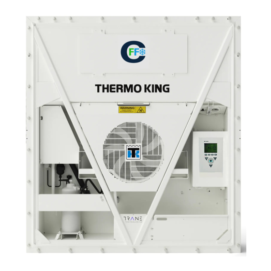
Unit Description General Description Units are all-electric, single-piece, refrigeration units with bottom air supply. The unit is designed to cool and heat containers for shipboard or overland transit. The unit mounts in the front wall of the container. Fork lift pockets are provided for installation and removal of the unit The frame and bulkhead panels are constructed of aluminum and are treated to resist corrosion.
-
Page 28: Digital Port
U U n n i i t t D D e e s s c c r r i i p p t t i i o o n n Digital Port The digital port provides cooling capacity control. The digital port is located at the top of the scroll assembly on the compressor body.
-
Page 29: Compressor Digital Control Valve
U U n n i i t t D D e e s s c c r r i i p p t t i i o o n n Part number for the MP3000 MRB fuse (F 20 amp 500V and red fuse holder) is: P/N 419318 Fuse & Holder Red MP3000. Fuse and fuse holder will be sold together as a kit.
-
Page 30: Fresh Air Exchange System
U U n n i i t t D D e e s s c c r r i i p p t t i i o o n n • Compressor Discharge Temperature Sensor • Ambient Air Fresh Air Exchange System The fresh air exchange system removes harmful gases from containers carrying sensitive perishable commodities.
-
Page 31: Condenser Fan Control
U U n n i i t t D D e e s s c c r r i i p p t t i i o o n n • Frozen Loads: Evaporator fans operate on low speed. If Optimized mode is on: •…
-
Page 32: Remote Monitoring Modem (Rmm, Rmm+) (Optional)
Condenser Fan Selection switch or a Water Pressure switch. Starting April 2005, Thermo King has added a shutoff valve on the outlet tube of the water-cooled condenser. Condenser fan switch is a software key. This switch is provided on the control box with the water-cooled condenser option.
-
Page 33: Afam Vent Door Assembly
U U n n i i t t D D e e s s c c r r i i p p t t i i o o n n Vent Door Door Control Module Interface Module Board and Cable (mounts in Control Box) Grille AFAM Vent Door Assembly…
-
Page 34
U U n n i i t t D D e e s s c c r r i i p p t t i i o o n n Unit Front View Evaporator Access Door Condenser Fan Compressor Compartment Scroll Compressor Control Box Rear Download and USDA Receptacle Panel… -
Page 35
U U n n i i t t D D e e s s c c r r i i p p t t i i o o n n Figure 3. Refrigeration System Expansion Valve Receiver Tank Low Pressure Cutout Switch Evaporator Coil Scroll Compressor Economizer Heat Exchanger… -
Page 36
U U n n i i t t D D e e s s c c r r i i p p t t i i o o n n Figure 4. Electrical Components Sensor Kit Heater Group Humidity Sensor Cable Connection Evaporator Fans Condenser Fan Motor… -
Page 37: Mp4000 Controller
Controller Description MP4000 Controller The MP4000 is an advanced microprocessor controller. It has been specially developed for the control and monitoring of refrigeration units. The controller contains the following basic features: • Temperature/Message Status Display – Temperature area: Displays return air sensor, supply air sensor, and setpoint. –…
-
Page 38: Idle Screen And Check Symbol
C C o o n n t t r r o o l l l l e e r r D D e e s s c c r r i i p p t t i i o o n n Figure 5.
-
Page 39: Display Icons
C C o o n n t t r r o o l l l l e e r r D D e e s s c c r r i i p p t t i i o o n n •…
-
Page 40: Mode Descriptions
C C o o n n t t r r o o l l l l e e r r D D e e s s c c r r i i p p t t i i o o n n Compressor On Loaded without Vapour Injection Battery Error (Datalogger Battery) Compressor On Loaded with Vapour Injection…
-
Page 41: Special Function Keys
F4 MENU Key: Press to view the extended Menu for the MP4000. Special Function Keys The Special Function keys are located around the Thermo King logo. These special function key allow the operator to move quickly to perform a specific function •…
-
Page 42: Software Versions
C C o o n n t t r r o o l l l l e e r r D D e e s s c c r r i i p p t t i i o o n n Software Versions The various software versions are listed below.
-
Page 43
C C o o n n t t r r o o l l l l e e r r D D e e s s c c r r i i p p t t i i o o n n Table 11. -
Page 44
C C o o n n t t r r o o l l l l e e r r D D e e s s c c r r i i p p t t i i o o n n Table 15. -
Page 45
C C o o n n t t r r o o l l l l e e r r D D e e s s c c r r i i p p t t i i o o n n Table 20. -
Page 46
C C o o n n t t r r o o l l l l e e r r D D e e s s c c r r i i p p t t i i o o n n Table 23. -
Page 47
C C o o n n t t r r o o l l l l e e r r D D e e s s c c r r i i p p t t i i o o n n Table 28. -
Page 48
C C o o n n t t r r o o l l l l e e r r D D e e s s c c r r i i p p t t i i o o n n Table 32. -
Page 49
C C o o n n t t r r o o l l l l e e r r D D e e s s c c r r i i p p t t i i o o n n Table 38. -
Page 50: Function Keys
Operating Instructions Function Keys Function Keys ON/OFF Key Defrost Key PTI — Pre-trip Inspection Alarm Key C/F Key Setpoint Key Menu Key Unit On/Off Key ON — Unit will operate on Cool or Heat depending on the controller setpoint temperature and the container air temperature.
-
Page 51: Initiating A Manual Defrost
O O p p e e r r a a t t i i n n g g I I n n s s t t r r u u c c t t i i o o n n s s •…
-
Page 52: Main Menu
O O p p e e r r a a t t i i n n g g I I n n s s t t r r u u c c t t i i o o n n s s 2.
-
Page 53: Full Cool Mode
O O p p e e r r a a t t i i n n g g I I n n s s t t r r u u c c t t i i o o n n s s 3.
-
Page 54: Defrost Mode
O O p p e e r r a a t t i i n n g g I I n n s s t t r r u u c c t t i i o o n n s s a.
-
Page 55: Low Speed Fans Only
O O p p e e r r a a t t i i n n g g I I n n s s t t r r u u c c t t i i o o n n s s Low Speed Fans Only N N O O T T I I C C E E C C a a r r g g o o L L o o s s s s ! !
-
Page 56: Menu Scrolling Keys
Navigating Controller Operating Menu Figure 6. MP4000 Control Panel Display Menu Scrolling Keys Moving through these seven menus, their submenus, and entering commands requires the use of four keys: EXIT — Press the F1 key each time you want to exit a submenu shown in the message display. UP/ DOWN — Press the F2 or F3 key each time you want to scroll up or down in a menu or submenu shown in the Message Display;…
-
Page 57: Changing Screen Contrast
N N a a v v i i g g a a t t i i n n g g C C o o n n t t r r o o l l l l e e r r O O p p e e r r a a t t i i n n g g M M e e n n u u •…
-
Page 58: Main Menu
Main Menu Main Menu From the Standard Display, press the MENU F4 key to enter the Main Menu as shown below. The Main Menu allows access to several other submenus using the UP F3, DOWN F3, and ENTER F4 keys. The other submenus are described below.
-
Page 59: Cold Treatment (Ct)
M M a a i i n n M M e e n n u u Figure 7. Controls Menu and Controls Overview Cold Treatment (CT) This feature is designed to maintain a temperature below the actual set point for a period of time, (per USDA specifications) and then increase the temperature to the final set point.
-
Page 60: Optiset
M M a a i i n n M M e e n n u u Figure 9. Multiple Temperature Set OptiSet™ ™ Allows all the AFAM variable to be set by selecting a specify commodity. Refer to (“Change the AFAM+ Settings Using OptiSet™,”…
-
Page 61: Pull Down Selection
M M a a i i n n M M e e n n u u • Bulb mode LOW: Evaporator fan low speed only. • Bulb mode CYCLE: Evaporator fan cycle — fans will cycle between low and high speed every 60 minutes, starting with the low speed fan operation first for 60 minutes.
-
Page 62: Dehumidify Control
M M a a i i n n M M e e n n u u Figure 13. Water Cooled Condenser Dehumidify Control During Chill mode operation, a dehumidification function is available (optional after Sep 2019) to reduce the relative humidity in the container to the desired humidity setpoint.
-
Page 63: Avl (Air Ventilation Logging)
M M a a i i n n M M e e n n u u Figure 15. Dehumidify Setpoint AVL (Air Ventilation Logging) The Fresh Air Exchange Recorder (AVL) detects vent disk movement and automatically displays a value in the LCD display for values of 0 to 125 m3/h.
-
Page 64: Fresh Air Vent Man — Afam+ Mode
M M a a i i n n M M e e n n u u Figure 17. AFAM Mode Fresh Air Vent Man — AFAM+ Mode Can be set to OFF, AFAM, or AFAM+. OFF — Will override all settings and keep the AFAM door completely closed. AFAM — Will allow and air exchange Rate and or Delay to be set.
-
Page 65: Afam Rate
M M a a i i n n M M e e n n u u Figure 19. AFAM Delay AFAM Rate Use to set AFAM door opens to desired rate, selectable from 0 CMH to 225 CMH. Figure 20. AFAM Rate AFAM+ CO2 Max Used to set the highest level of Carbon Dioxide allowed in the container.
-
Page 66: Afam+ O2 Min
M M a a i i n n M M e e n n u u Figure 21. CO2 Max AFAM+ O2 Min Used to set the lowest level of Oxygen allowed in the container. The AFAM+ door will open or close to maintain this level.
-
Page 67: Silent Mode
M M a a i i n n M M e e n n u u Figure 23. Smart PTI Silent Mode Silent mode is a way to make the reefer unit silent without manual switching it OFF and ON. The feature is normally used when the reefer unit is located near public areas where the noise from the unit is annoying and not acceptable during ie.
-
Page 68: Alarm Menu
M M a a i i n n M M e e n n u u BEE681 BEE680 BEE680 At the temperature log the flag ‘s’ will be set to indicate the halted operation. Changing the configuration of the mode is documented in the event log. Since the unit is not allowed to operate during the silent period, the normal surveillance is not ongoing.
-
Page 69: Alarm Code States
M M a a i i n n M M e e n n u u Figure 24. No Alarms or Newest Alarm Alarm Code States There are three alarm code states for Shutdown and Check alarms: • Active: A code condition has occurred and continues to exist in the unit or the code condition occurred within the past one hour but does not currently exist in the unit.
-
Page 70: Configuration Menu
M M a a i i n n M M e e n n u u For a complete list of status messages and controller actions, refer to (“Status Messages and Controller Actions,” p. 160). Figure 25. No Messages or Newest Message Configuration Menu The Configuration menu displays a list of functions that identifies unit operating features and current settings.
-
Page 71: Unit
M M a a i i n n M M e e n n u u Unit Figure 27. Unit Menu and Unit Overview • In-Range Temperature limit: Sets the temperature value for the controller’s in-range LED and datalogger functions (factory default = 1.5 C [2.7 F]).
-
Page 72: Options
M M a a i i n n M M e e n n u u Options This menu is used to turn ON/OFF a Module/Feature, select a particular option within a module, and tell the controller when a sensor is mounted. •…
-
Page 73
M M a a i i n n M M e e n n u u TK 60275-4-MM-EN… -
Page 74: System
M M a a i i n n M M e e n n u u System N N o o t t e e : : Units without a container number beginning with MAE, MSF, or MWC must be set for USDA temperature sensing. Figure 28.
-
Page 75: Clock
M M a a i i n n M M e e n n u u Clock Displays current Date and Time, which can be edited. 1. Press the F4 key. Press the F3 key to scroll down to the CONFIGURATION Menu. 2.
-
Page 76: Calibrate
M M a a i i n n M M e e n n u u Calibrate Used to calibrate sensor probes. For Cld Treatment refer to “Cold Treatment (CT),” p. 104 Icon Menu 1. Press the F2 or F3 UP/DOWN key to scroll to the Configuration selection and press the F4 key. The Configuration Menu will appear.
-
Page 77: Log View Menu
M M a a i i n n M M e e n n u u 3. Press the F4 key. The Configuration Menu will appear. 4. Press the F2 or F3 UP/DOWN key to scroll to the Classic Menu selection. 5.
-
Page 78: Info Menu
M M a a i i n n M M e e n n u u Info Menu This menu displays controller software application version, bootloader version, power module version, serial number, and option file version. It also displays expansion slots if used. Figure 30.
-
Page 79: Pti Key
Special Function Keys — User Activated Commands PTI Key Pressing the PTI key will access various PTI Commands for selecting a user activated functionality. • Manual Function Test: Refer to (“Manual Function Test,” p. 81) for detailed information. • Function Test: Refer to (“Function Test,”…
-
Page 80: Defrost Key
S S p p e e c c i i a a l l F F u u n n c c t t i i o o n n K K e e y y s s — — U U s s e e r r A A c c t t i i v v a a t t e e d d C C o o m m m m a a n n d d s s Show PTI Info Defrost Key To access the Defrost Menu, turn the unit On and allow the unit to start and stabilize and show the unit status display…
-
Page 81: Pti (Pretrip) Tests
S S p p e e c c i i a a l l F F u u n n c c t t i i o o n n K K e e y y s s — — U U s s e e r r A A c c t t i i v v a a t t e e d d C C o o m m m m a a n n d d s s PTI (Pretrip) Tests N N O O T T I I C C E E C C a a r r g g o o L L o o s s s s ! !
-
Page 82
S S p p e e c c i i a a l l F F u u n n c c t t i i o o n n K K e e y y s s — — U U s s e e r r A A c c t t i i v v a a t t e e d d C C o o m m m m a a n n d d s s •… -
Page 83
S S p p e e c c i i a a l l F F u u n n c c t t i i o o n n K K e e y y s s — — U U s s e e r r A A c c t t i i v v a a t t e e d d C C o o m m m m a a n n d d s s Table 40. -
Page 84
S S p p e e c c i i a a l l F F u u n n c c t t i i o o n n K K e e y y s s — — U U s s e e r r A A c c t t i i v v a a t t e e d d C C o o m m m m a a n n d d s s Table 40. -
Page 85: Function Test
S S p p e e c c i i a a l l F F u u n n c c t t i i o o n n K K e e y y s s — — U U s s e e r r A A c c t t i i v v a a t t e e d d C C o o m m m m a a n n d d s s Table 40.
-
Page 86
Air Ventilation Logging (AVL) The Air Ventilation Logging option detects vent disk movement and automatically displays a value on the display. This value is also logged in the datalogger. The entry records the time, date, and vent opening position. It is mounted on the fresh air vent door. -
Page 87: Starting The Afam System
Advanced Fresh Air Management (AFAM) System Starting the AFAM System 1. Press the F4 key to enter the main menu. Press the F2 or F3 key to scroll to Config menu and press F4 to expand the menu. 2. Press the F2 or F3 key to scroll to Options menu and press F4 to expand the menu. 3.
-
Page 88: Change The Afam Delay
A A d d v v a a n n c c e e d d F F r r e e s s h h A A i i r r M M a a n n a a g g e e m m e e n n t t ( ( A A F F A A M M ) ) S S y y s s t t e e m m 9.
-
Page 89: Change The Afam Rate
A A d d v v a a n n c c e e d d F F r r e e s s h h A A i i r r M M a a n n a a g g e e m m e e n n t t ( ( A A F F A A M M ) ) S S y y s s t t e e m m 4.
-
Page 90: Set Afam+ System Values
Advanced Fresh Air Management Plus (AFAM+) System An advanced microprocessor controlled fresh air management system that provides: • programmable control of the CO2 level in the container • data logging of the CO2 gas level reading • gas sensor unit •…
-
Page 91: Change The Afam Delay
A A d d v v a a n n c c e e d d F F r r e e s s h h A A i i r r M M a a n n a a g g e e m m e e n n t t P P l l u u s s ( ( A A F F A A M M + + ) ) S S y y s s t t e e m m 9.
-
Page 92: Change The Afam+ Settings Using Optiset
A A d d v v a a n n c c e e d d F F r r e e s s h h A A i i r r M M a a n n a a g g e e m m e e n n t t P P l l u u s s ( ( A A F F A A M M + + ) ) S S y y s s t t e e m m The CO2 rate sets the desired CO2 level in the container when a gas sensor unit is installed.
-
Page 93: Modify Optiset Product Settings
A A d d v v a a n n c c e e d d F F r r e e s s h h A A i i r r M M a a n n a a g g e e m m e e n n t t P P l l u u s s ( ( A A F F A A M M + + ) ) S S y y s s t t e e m m 4.
-
Page 94: System Operation Verification
A A d d v v a a n n c c e e d d F F r r e e s s h h A A i i r r M M a a n n a a g g e e m m e e n n t t P P l l u u s s ( ( A A F F A A M M + + ) ) S S y y s s t t e e m m System Operation Verification If the system appears not to be operating properly, it is best to verify that the controller can recognize if the AFAM+ option is installed.
-
Page 95
A A d d v v a a n n c c e e d d F F r r e e s s h h A A i i r r M M a a n n a a g g e e m m e e n n t t P P l l u u s s ( ( A A F F A A M M + + ) ) S S y y s s t t e e m m N N O O T T I I C C E E E E q q u u i i p p m m e e n n t t D D a a m m a a g g e e ! ! I I f f t t h h e e i i n n l l e e t t / / o o u u t t l l e e t t t t u u b b e e s s o o r r f f i i l l t t e e r r n n e e e e d d t t o o b b e e c c l l e e a a r r e e d d , , d d i i s s c c o o n n n n e e c c t t f f r r o o m m t t h h e e g g a a s s a a n n a a l l y y z z e e r r B B E E F F O O R R E E p p u u r r g g i i n n g g a a i i r r… -
Page 96: Afam+ Door Closes Automatically
Pulsating Vent Door AFAM+ Door Closes Automatically On units equipped with the AFAM option, a harness from J_B12 to the on/off switch, and a container prefix of HLXU. If the AFAM door is open it will close automatically if the on/off switch is turned off. Unit and controller will shut off and the AFAM door will be power close.
-
Page 97: Chill Loads (Setpoint At -9.9 C [14.1 F] And Above)
Operating Theory Chill Loads (Setpoint at -9.9 C [14.1 F] and Above) The unit operates on Cool with Modulation and Heat to provide accurate control of chill loads. During Cool with Modulation, the controller uses a proportional-integral derivative (PID) algorithm, and a Digital Control valve to provide accurate control of the container temperature in direct response to load demand.
-
Page 98: Chill Loads (Setpoints Of -9.9 C [14.1 F] And Above)
O O p p e e r r a a t t i i n n g g T T h h e e o o r r y y Chill Loads (Setpoints of -9.9 C [14.1 F] and Above) When the Optimized Mode is set to ON, the evaporator fans operate on low and high speed as needed to maintain the setpoint and save energy.
-
Page 99: Continuous Temperature Control Operation
O O p p e e r r a a t t i i n n g g T T h h e e o o r r y y Continuous Temperature Control Operation Chill Loads (Controller Setpoint at -9.9 C [14.1 F] and Above) The controller regulates the compressor, digital control valve, and electric heaters based on a Control Temperature Differential (Refer to “Compressor Digital Control Valve,”…
-
Page 100
O O p p e e r r a a t t i i n n g g T T h h e e o o r r y y Table 41. CFF Operating Mode Function Chart (continued) Chill Loads Setpoints at -9.9 C Frozen Loads Setpoints (14.4 F) and Above at -10 C (14 F) and… -
Page 101: Cool With Modulation
O O p p e e r r a a t t i i n n g g T T h h e e o o r r y y Cool with Modulation • Controller calls for the Cool mode whenever the Control Temperature Differential (based on supply air temperature) is above setpoint.
-
Page 102: Cool
O O p p e e r r a a t t i i n n g g T T h h e e o o r r y y Cool • After initial start-up and pull-down to 2.0 C (3.6 F) below setpoint, the controller calls for the Cool mode whenever: –…
-
Page 103: Compressor Digital Control Valve
O O p p e e r r a a t t i i n n g g T T h h e e o o r r y y • The Heat and Defrost indicators turn off and the solid state is de-energized. The controller starts the compressor to pre-cool the evaporator coil.
-
Page 104: Data Recording And Downloading Data
O O p p e e r r a a t t i i n n g g T T h h e e o o r r y y Data Recording and Downloading Data The data logger can record sensor temperatures as well as loss of power, alarms, sensor failure, setpoint change and unit shutdown events.
-
Page 105
O O p p e e r r a a t t i i n n g g T T h h e e o o r r y y Figure 34. Details of CT Log Commodity is loaded Final set point Commodity reached Pre-cool… -
Page 106
O O p p e e r r a a t t i i n n g g T T h h e e o o r r y y USDA Type screen in the Configuration menu must be set to the correct sensor setting and each USDA sensor must be calibrated to comply with USDA temperature recording requirements. -
Page 107: Multiple Temperature Setpoint (Mts)
O O p p e e r r a a t t i i n n g g T T h h e e o o r r y y S S u u r r v v e e i i l l l l a a n n c c e e d d u u r r i i n n g g c c o o l l d d t t r r e e a a t t m m e e n n t t : : During the CT period all USDA sensors can fail and the CT period will continue. The fail state will be shown in the temperature log.
-
Page 108
O O p p e e r r a a t t i i n n g g T T h h e e o o r r y y S S t t a a r r t t i i n n g g a a n n d d S S e e t t t t i i n n g g M M u u l l t t i i p p l l e e T T e e m m p p e e r r a a t t u u r r e e S S e e t t p p o o i i n n t t 1. -
Page 109
O O p p e e r r a a t t i i n n g g T T h h e e o o r r y y 5. The following screen will appear. Repeat steps 3 and 4 for Setpoint 2 and Period 2, and for each additional setpoint that is required. -
Page 110
O O p p e e r r a a t t i i n n g g T T h h e e o o r r y y 3. The Standard Display will appear and “MTS — Approaching setting 1” will disappear. After stopping MTS, the unit will continue running with the last MTS setpoint in action. -
Page 111: Controller Door Open And Close Instructions
Controller Maintenance Controller Door Open and Close Instructions O O p p e e n n Insert a flat blade screwdriver into slot Move the screwdriver handle to the left With the door catch released, pull door on side of control box door. to release the door catch from the box out and open.
-
Page 112
C C o o n n t t r r o o l l l l e e r r M M a a i i n n t t e e n n a a n n c c e e / MP4000 / command.ini 3/18/2010 / Logs (Downloads will appear here) / Firmware CM4000_3.2.0.0_140822.strip Figure 36. -
Page 113: Mp4000 Test System Tool
C C o o n n t t r r o o l l l l e e r r M M a a i i n n t t e e n n a a n n c c e e 2.
-
Page 114: Controller Replacement
C C o o n n t t r r o o l l l l e e r r M M a a i i n n t t e e n n a a n n c c e e •…
-
Page 115: Unit Protection Devices
Electrical Maintenance Unit Protection Devices Main Circuit Breaker The main power circuit breaker is located in the control box. The 25 ampere manual reset circuit breaker is located in the Control Box. It protects the 460/380V power supply circuit to the unit electric motors and control system transformer.
-
Page 116: High Pressure Cutout Manifold
E E l l e e c c t t r r i i c c a a l l M M a a i i n n t t e e n n a a n n c c e e Low Pressure Cutout Switch High Pressure Cutout Switch •…
-
Page 117: High Pressure Cutout Switch Removal/Installation
E E l l e e c c t t r r i i c c a a l l M M a a i i n n t t e e n n a a n n c c e e 3.
-
Page 118: Low Pressure Cutout Switch
E E l l e e c c t t r r i i c c a a l l M M a a i i n n t t e e n n a a n n c c e e Low Pressure Cutout Switch A low pressure cutout switch is located on the compressor suction line.
-
Page 119: Low Pressure Cutout Switch Or Suction Transducer Configuration
E E l l e e c c t t r r i i c c a a l l M M a a i i n n t t e e n n a a n n c c e e Suction Transducer Discharge Transducer Suction Service Valve…
-
Page 120: Discharge And Low Pressure Sensors (Optional)
E E l l e e c c t t r r i i c c a a l l M M a a i i n n t t e e n n a a n n c c e e 6.
-
Page 121: Reversing Power Phase On Units
E E l l e e c c t t r r i i c c a a l l M M a a i i n n t t e e n n a a n n c c e e If an evaporator fan is rotating backwards on one or both speeds, refer to the unit wiring diagram to correct motor wiring at the fan motor junction box or evaporator fan contactor (disconnect power supply before reversing leads).
-
Page 122: Extended Capacity Heaters
E E l l e e c c t t r r i i c c a a l l M M a a i i n n t t e e n n a a n n c c e e Six Short Length Heaters (680 Watts Each) Three Longer Heaters (1360 or 2000 Watts Each) Extended Capacity Heaters…
-
Page 123: Compressor Discharge Temperature Sensor
E E l l e e c c t t r r i i c c a a l l M M a a i i n n t t e e n n a a n n c c e e the evaporator cover from the rear of the unit and replace the heater or correct any defective wiring.
-
Page 124: Temperature Sensors
E E l l e e c c t t r r i i c c a a l l M M a a i i n n t t e e n n a a n n c c e e Temperature Sensors Thermistor type temperature sensors are used.
-
Page 125: Sensor Testing
E E l l e e c c t t r r i i c c a a l l M M a a i i n n t t e e n n a a n n c c e e Sensor Testing The controller constantly monitors the left hand and right hand supply sensors, return sensor and defrost (evaporator coil) sensor to determine when to initiate a demand defrost.
-
Page 126
E E l l e e c c t t r r i i c c a a l l M M a a i i n n t t e e n n a a n n c c e e Table 43. -
Page 127: Introduction
Refrigeration Maintenance Introduction The following procedures involve servicing the refrigeration system. Some of these service procedures are regulated by Federal, and in some cases, by State and Local laws. N N o o t t e e : : In the USA, EPA Section 608 Certification is required to work on refrigeration systems, using approved equipment and complying with all Federal, State, and Local laws.
-
Page 128: Oil Acid Test
R R e e f f r r i i g g e e r r a a t t i i o o n n M M a a i i n n t t e e n n a a n n c c e e •…
-
Page 129: Gauge Manifold Set
R R e e f f r r i i g g e e r r a a t t i i o o n n M M a a i i n n t t e e n n a a n n c c e e Service Valve Open to Port (Servicing Position) 1/2 Turn In Service Valve Front Seated (Check or Remove…
-
Page 130
R R e e f f r r i i g g e e r r a a t t i i o o n n M M a a i i n n t t e e n n a a n n c c e e Removing Refrigerant Quick Disconnect Access Valve Discharge Service Valve (DSV) -
Page 131: Gauge Manifold Set Installation & Removal
Gauge Manifold Set Installation & Removal Thermo King recommends the use of access valves or self-sealing, quick disconnect fittings. This limits the loss of refrigerant into the atmosphere. A separate gauge manifold set with low loss fittings (refer to Tool Catalog) should be dedicated for use with R-404A/R-452A only.
-
Page 132: Removal
R R e e f f r r i i g g e e r r a a t t i i o o n n M M a a i i n n t t e e n n a a n n c c e e Purging Gauge Manifold Suction Connection Discharge Connection…
-
Page 133: Receiver Tank Sight Glass
R R e e f f r r i i g g e e r r a a t t i i o o n n M M a a i i n n t t e e n n a a n n c c e e 2.
-
Page 134
R R e e f f r r i i g g e e r r a a t t i i o o n n M M a a i i n n t t e e n n a a n n c c e e TK 60275-4-MM-EN… -
Page 135: Using Pressurized Nitrogen
R R e e f f r r i i g g e e r r a a t t i i o o n n M M a a i i n n t t e e n n a a n n c c e e Using Pressurized Nitrogen The improper use of high pressure cylinders can cause physical damage to components, or personal injury, or cause stress that would lead to failure of components.
-
Page 136: Maximum Gas Pressures
R R e e f f r r i i g g e e r r a a t t i i o o n n M M a a i i n n t t e e n n a a n n c c e e 4.
-
Page 137
R R e e f f r r i i g g e e r r a a t t i i o o n n M M a a i i n n t t e e n n a a n n c c e e Special, self-sealing quick disconnect Iso Valve To 220/190 Vac Power… -
Page 138: Recovering Refrigerant From System
U U s s e e o o n n l l y y r r e e f f r r i i g g e e r r a a n n t t r r e e c c o o v v e e r r y y e e q q u u i i p p m m e e n n t t a a p p p p r r o o v v e e d d f f o o r r a a n n d d d d e e d d i i c c a a t t e e d d t t o o R R — — 1 1 3 3 4 4 A A r r e e c c o o v v e e r r y y . . When removing any refrigerant from a Thermo King refrigeration system, use a recovery process that prevents or absolutely minimizes the refrigerant escaping to the atmosphere.
-
Page 139: Unit Preparation And Hookup
Evacuate the system to 500 microns to achieve a final equilibrium pressure of 2000 microns or less. The final equilibrium pressure is determined with the Thermo King Evacuation Station using the following procedure (called a pressure rise test): a.
-
Page 140: Pressure Rise Test
R R e e f f r r i i g g e e r r a a t t i i o o n n M M a a i i n n t t e e n n a a n n c c e e •…
-
Page 141: Heat Saves Time
R R e e f f r r i i g g e e r r a a t t i i o o n n M M a a i i n n t t e e n n a a n n c c e e •…
-
Page 142: Compressor Replacement
R R e e f f r r i i g g e e r r a a t t i i o o n n M M a a i i n n t t e e n n a a n n c c e e Compressor Replacement Removal 1.
-
Page 143: Condenser Coil Replacement
R R e e f f r r i i g g e e r r a a t t i i o o n n M M a a i i n n t t e e n n a a n n c c e e Scroll Compressor Suction Service Valve Discharge Service Valve…
-
Page 144: Installation
R R e e f f r r i i g g e e r r a a t t i i o o n n M M a a i i n n t t e e n n a a n n c c e e 3.
-
Page 145: Economizer Expansion Valve Replacement
R R e e f f r r i i g g e e r r a a t t i i o o n n M M a a i i n n t t e e n n a a n n c c e e 2.
-
Page 146: Installation
3. Solder inlet and outlet line connections to economizer expansion valve and clean solder connections with baking soda. Apply black paint to area to prevent corrosion. N N o o t t e e : : Thermo King strongly recommends that dry nitrogen be used to purge the system during any solder operations (Refer to “Using Pressurized Nitrogen,”…
-
Page 147
R R e e f f r r i i g g e e r r a a t t i i o o n n M M a a i i n n t t e e n n a a n n c c e e Apply heat transfer paste to bulb holder before installing TXV bulb. -
Page 148: Economizer Heat Exchanger Replacement
2. Clean the two liquid and two suction lines for soldering. I I m m p p o o r r t t a a n n t t : : Thermo King strongly recommends that dry nitrogen be used to purge the system during any solder operations (Refer to “Using Pressurized Nitrogen,”…
-
Page 149: Vapor Injection Valve Replacement
R R e e f f r r i i g g e e r r a a t t i i o o n n M M a a i i n n t t e e n n a a n n c c e e Figure 40.
-
Page 150: Compressor Digital Control Valve Replacement
R R e e f f r r i i g g e e r r a a t t i i o o n n M M a a i i n n t t e e n n a a n n c c e e N N O O T T I I C C E E E E q q u u i i p p m m e e n n t t D D a a m m a a g g e e ! ! U U s s e e a a h h e e a a t t s s i i n n k k o o r r w w r r a a p p s s w w i i t t c c h h w w i i t t h h w w e e t t r r a a g g s s t t o o p p r r e e v v e e n n t t d d a a m m a a g g e e t t o o n n e e w w s s w w i i t t c c h h .
-
Page 151
R R e e f f r r i i g g e e r r a a t t i i o o n n M M a a i i n n t t e e n n a a n n c c e e N N O O T T I I C C E E E E q q u u i i p p m m e e n n t t D D a a m m a a g g e e ! ! U U s s e e a a h h e e a a t t s s i i n n k k o o r r w w r r a a p p s s w w i i t t c c h h w w i i t t h h w w e e t t r r a a g g s s t t o o p p r r e e v v e e n n t t d d a a m m a a g g e e t t o o n n e e w w s s w w i i t t c c h h . -
Page 152: Taking Care Of The Structure
Servicing the Unit Taking Care of the Structure Inspecting Unit Inspect the unit during unit pretrip inspection and every 1,000 operating hours for loose or broken wires or hardware, compressor oil leaks, or other physical damage which can affect unit performance and require repair or replacement of parts.
-
Page 153: Cleaning The Evaporator Coil
S S e e r r v v i i c c i i n n g g t t h h e e U U n n i i t t Cleaning the Evaporator Coil N N O O T T I I C C E E E E q q u u i i p p m m e e n n t t D D a a m m a a g g e e ! ! T T h h e e a a i i r r p p r r e e s s s s u u r r e e s s h h o o u u l l d d n n o o t t b b e e h h i i g g h h e e n n o o u u g g h h t t o o d d a a m m a a g g e e c c o o i i l l f f i i n n s s .
-
Page 154: Adjusting The Fresh Air Exchange System
S S e e r r v v i i c c i i n n g g t t h h e e U U n n i i t t Adjusting the Fresh Air Exchange System The fresh air exchange system has an adjustable vent door for ventilation. The evaporator fans draw in outside air through an air intake and discharge an equal amount of container air through an air outlet.
-
Page 155: Introduction
Diagnostics Introduction This section includes the following: • Controller Diagnostics • Mechanical Diagnostics • Refrigeration Diagnostics • Status Messages and Controller Actions • Alarm Codes and Corrective Actions The tables shown will help identify and fix unit problems. MP4000 Diagnostics The MP4000 can be a very helpful diagnostic tool.
-
Page 156: Mechanical Diagnostics
D D i i a a g g n n o o s s t t i i c c s s Mechanical Diagnostics Condition Possible Cause Remedy Compressor does not operate — no amperage Controller on; unit start sequence still timing. Wait up to two minutes for compressor start- draw.
-
Page 157
D D i i a a g g n n o o s s t t i i c c s s Condition Possible Cause Remedy Compressor contactor burned out. Low line voltage. Increase line voltage to at least 90 percent of compressor motor rating. -
Page 158: Refrigeration Diagnostics
D D i i a a g g n n o o s s t t i i c c s s Refrigeration Diagnostics Condition Possible Cause Remedy Load temperature too high — unit not cooling. Compressor does not operate. Refer to (“Mechanical Diagnostics,”…
-
Page 159
D D i i a a g g n n o o s s t t i i c c s s Condition Possible Cause Remedy Compressor loses oil. Refrigerant leak. Repair leak and recharge. Compressor oil migrates to system. Short cycling. -
Page 160: Status Messages And Controller Actions
D D i i a a g g n n o o s s t t i i c c s s Status Messages and Controller Actions The controller displays status messages (in Alarms Menu) on the display for several general faults. More than one status message may appear at a time.
-
Page 161
D D i i a a g g n n o o s s t t i i c c s s Status Description Controller Action/Corrective Action Message Current Too High — Check Compressor and Fans • Enter Manual Function Test menu and test (operate) each •… -
Page 162
D D i i a a g g n n o o s s t t i i c c s s Status Description Controller Action/Corrective Action Message Evaporator Coil Temperature Too Low — Check Evaporator • Use DATA menu to inspect readings. Sensor •… -
Page 163
D D i i a a g g n n o o s s t t i i c c s s Status Description Controller Action/Corrective Action Message HPCO Timer Hold — Please Wait • Controller clears message on compressor start-up. •… -
Page 164
D D i i a a g g n n o o s s t t i i c c s s Status Description Controller Action/Corrective Action Message Compressor High Temperature • The message clears itself when the compressor • When: temperature is normal. -
Page 165
D D i i a a g g n n o o s s t t i i c c s s Status Description Controller Action/Corrective Action Message Power Module Heat Exchanger High Temperature • Check for blocked air flow to the back side of the control •… -
Page 166: Alarm Codes And Corrective Actions
D D i i a a g g n n o o s s t t i i c c s s Alarm Codes and Corrective Actions N N o o t t e e : : Sensors used with the MP4000 controller do not require calibration. Check sensor resistance with an ohmmeter. Shutdown Alarm (Level 1 Alarm): Alarm light on display flashes and unit stops.
-
Page 167
D D i i a a g g n n o o s s t t i i c c s s Code Description Corrective Action Return Air Temperature Sensor Open Circuit • Check for damaged sensor wires. • When the sensor circuit resistance is higher than 1300Ω. •… -
Page 168
D D i i a a g g n n o o s s t t i i c c s s Code Description Corrective Action Evaporator Coil Temperature Sensor Open Circuit • Check for damaged sensor wires. • When the sensor circuit resistance is higher than 1300Ω. •… -
Page 169
D D i i a a g g n n o o s s t t i i c c s s Code Description Corrective Action Compressor Current Too High • Check evaporator and condenser sensor temperatures for • Occurs during pretrip (PTI) or function test only. correct value (±… -
Page 170
D D i i a a g g n n o o s s t t i i c c s s Code Description Corrective Action Heater Current Too Low • Enter Manual Function Test and turn heaters on. Check •… -
Page 171
D D i i a a g g n n o o s s t t i i c c s s Code Description Corrective Action Evaporator Fan High Speed Current Too Low • Open evaporator door and make sure all fans rotate freely. •… -
Page 172
D D i i a a g g n n o o s s t t i i c c s s Code Description Corrective Action Evaporator Fan Low Speed Current Too Low • Open evaporator door and make sure all fans rotate freely. •… -
Page 173
D D i i a a g g n n o o s s t t i i c c s s Code Description Corrective Action Power Supply Phase Error • Check fuses on the power module. • Shutdown Alarm •… -
Page 174
D D i i a a g g n n o o s s t t i i c c s s Code Description Corrective Action Capacity Test 2 Error • Enter Manual Function Test and start evaporator fans on •… -
Page 175
D D i i a a g g n n o o s s t t i i c c s s Code Description Corrective Action Condenser Coil Temperature Sensor Open Circuit • Check for damaged sensor wires. • When the sensor circuit resistance is above 1785Ω. •… -
Page 176
D D i i a a g g n n o o s s t t i i c c s s Code Description Corrective Action Ambient Air Temperature Sensor Open Circuit • Check for damaged sensor wires. • When the sensor circuit resistance is above 1785Ω. •… -
Page 177
D D i i a a g g n n o o s s t t i i c c s s Code Description Corrective Action Return Air Temperature Too Low • Using DATA menu to evaluate sensors. • Occurs during Normal Run only. •… -
Page 178
D D i i a a g g n n o o s s t t i i c c s s Code Description Corrective Action High Pressure Switch On Error • Check discharge and suction pressure gauge readings. • Occurs during pretrip (PTI) test only. -
Page 179
D D i i a a g g n n o o s s t t i i c c s s Code Description Corrective Action Delta Current Error • Enter Manual Function Test menu and test (operate) each • 100% ampere difference between current phases, max 3-phase component to locate defective connection. -
Page 180
D D i i a a g g n n o o s s t t i i c c s s Code Description Corrective Action Gas Analyzer Error • Redo AFAM+ PTI. • Occurs during Pre-Trip (PTI) test only. •… -
Page 181
D D i i a a g g n n o o s s t t i i c c s s Code Description Corrective Action Compressor temperature Sensor Open Circuit • Check for damaged sensor wires. • When the sensor circuit resistance is above 1MΩ and the •… -
Page 182
D D i i a a g g n n o o s s t t i i c c s s Code Description Corrective Action Compressor temperature Sensor Short Circuit • Check for damaged sensor wires. • When the sensor circuit resistance is below 550Ω. •… -
Page 183
D D i i a a g g n n o o s s t t i i c c s s Code Description Corrective Action Discharge Pressure Sensor Error • Using DATA menu evaluate sensor readings. • Occurs during Normal Run if the sensor is detected to be •… -
Page 184
D D i i a a g g n n o o s s t t i i c c s s Code Description Corrective Action Supply Air Temperature Sensor Error • Use the DATA menu to detect the failing sensor. •… -
Page 185
D D i i a a g g n n o o s s t t i i c c s s Code Description Corrective Action Power Module Network Error • Check connection between controller and power module. • The surveillance has not received valid status •… -
Page 186
D D i i a a g g n n o o s s t t i i c c s s Code Description Corrective Action Evaporator Section Too Hot • Observe temperature readings to locate the problem. • Occurs if supply air, return air or evaporator coil •… -
Page 187
Diagrams Diagram Index Drawing No. Title Page 1E54051 MAGNUM Wiring Diagram Figure 43, p. 188 Figure 44, p. 189 1E54052 MAGNUM Schematic Diagram Figure 45, p. 190 TK 52234 MAGNUM PLUS Refrigeration System Components Figure 46, p. 191 Figure 47, p. 192 MP4000 Menu Flow Diagram Figure 48, p. -
Page 188
Figure 43. 1E54051 (Sheet 1 of 2) RELEASED 08/Apr/2019 12:55:38 GMT TK 60275-4-MM-EN… -
Page 189
Figure 44. 1E54051 (Sheet 2 of 2) RELEASED 08/Apr/2019 12:55:38 GMT TK 60275-4-MM-EN… -
Page 190
Figure 45. 1E54052 (Sheet 1 of 1) RELEASED 08/Apr/2019 12:55:39 GMT TK 60275-4-MM-EN… -
Page 191
Figure 46. MAGNUM PLUS Refrigeration System Components Low Pressure Vapor Low Pressure Liquid TK 52234 (2/3)-4-CH (Rev. 0), 10/03 High Pressure Vapor High Pressure Liquid Stage 1 Sub-Cooled High Pressure Liquid Stage 2 Sub-Cooled High Pressure Liquid TK 60275-4-MM-EN… -
Page 192
Figure 47. MAGNUM PLUS Components Scroll Compressor Discharge Service Valve High Pressure Switch Condenser Coil Receiver Tank Pressure Relief Sight Glass Drier / Oil Filter Economizer Heat Exchanger 10. Vapor Injection Valve Economizer TXV 12. Evaporator TXV 13. Evaporator Coil 14. -
Page 193
Figure 48. MP4000 Controller Menu Guide CONTROLLER MENU GUIDE • F1 ALARM • F2 C/F F3 SETPOINT • F4 MENU • NOTE: All screens are NOT present on all units. The screen Values Menu that display on the controller are determined by the Controller Software setting and the options installed on the Temperature Values Pressure Values… -
Page 194
N N o o t t e e s s TK 60275-4-MM-EN… -
Page 195
N N o o t t e e s s TK 60275-4-MM-EN… -
Page 196
1938. For more information, visit www.thermoking.com or www.tranetechnologies.com. Thermo King has a policy of continuous product and product data improvements and reserves the right to change design and specifications without notice. We are committed to using environmentally conscious print practices.
- Manuals
- Brands
- Trane Manuals
- Trucks
- Thermo King Magnum Plus
- Operator’s manual
-
Contents
-
Table of Contents
-
Troubleshooting
-
Bookmarks
Quick Links
Operator’s Manual
Manuel de l’utilisateur
Manual del operador
Betriebshandbuch
Bruksanvisning
MagnumPlus
Revision 0
TK-61110-4-OP
November 2013
Related Manuals for Trane Thermo King Magnum Plus
Summary of Contents for Trane Thermo King Magnum Plus
-
Page 1
Operator’s Manual Manuel de l’utilisateur Manual del operador Betriebshandbuch Bruksanvisning MagnumPlus Revision 0 TK-61110-4-OP November 2013… -
Page 2
Magnum + TK 61110-4-OP (Rev. 0, 11/13) -
Page 4: Table Of Contents
TABLE OF CONTENTS TABLE OF CONTENTS Table of Contents ……1 Standard Display ……….17 Safety Instructions ……2 Glossary of Symbols ………
-
Page 5: Safety Instructions
SAFETY INSTRUCTIONS SAFETY INSTRUCTIONS a ship). Refrigerant tends to displace air and Where turning of the unit is not possible (for can cause oxygen depletion. This can result example at voltage measuring or in suffocation and possible death. troubleshooting), follow safety precautions GENERAL PRECAUTIONS below.
-
Page 6: First Aid
SAFETY INSTRUCTIONS FIRST AID LOW VOLTAGE IMMEDIATE action must be initiated after a Control circuits are low voltage (24 Vac and 12 person has received an electrical shock. Obtain Vdc). This voltage potential is not considered immediate medical assistance. dangerous. Large amount of current available (over 30 amperes) can cause severe burns if The source of shock must be immediately shorted to ground.
-
Page 7
SAFETY INSTRUCTIONS AXA0214 AXA0215 AXA0216 Controller Nameplate Unit Nameplate Compressor Nameplate AXA0217 Nameplate and Warning Locations AXA0218 BEN074… -
Page 8: Identifying Unit Safety And Warning Decals
SAFETY INSTRUCTIONS IDENTIFYING UNIT SAFETY AND WARNING DECALS Serial number decals, refrigerant type decals and warning decals appear on all Thermo King equipment. These decals provide ® information that may be needed to service or repair the unit. Service technicians should read and follow the instructions on all warning decals.
-
Page 9: Unit Inspection
UNIT INSPECTION UNIT INSPECTION A closely followed maintenance program will help to keep your Thermo King unit in top operating condition. The following service guide table should be used as a guide when inspecting or servicing components on this unit. Pretrip Inspect These Items Electrical…
-
Page 10
UNIT INSPECTION… -
Page 11: Specifications
SPECIFICATIONS SPECIFICATIONS SYSTEM NET COOLING CAPACITY— FULL COOL MAGNUM+ Model — Air Cooled Condensing* 460/230V, 3 Phase, 60 Hz Power Net Cooling Capacity Power Consump Return air to evaporator coil inlet 60 Hz Capacity B/hr 60 Hz Capacity kW 60 Hz Power kW 21.1 C (70 F) 56,700 16.603…
-
Page 12
SPECIFICATIONS MAGNUM+ 460/230V, 3 Phase, 60 Hz Power 380/190V, 3 Phase, 50 Hz Power External Static High Speed Low Speed High Speed Low Speed Pressure (water column) /min /min /min /min 0 mm (0 in.) 6,560 3,860 3,170 1,865 5,480 3,225 2,710 1,595… -
Page 13
SPECIFICATIONS Locked Rotor Amps 3.9 amps @ 460V, 60 Hz; 3.7 amps @ 380V, 50 Hz Evaporator Fan Motors: Type 460/380V, 60/50 Hz, 3 Phase Kilowatts 0.75 kW @ 460V, 60 Hz Horsepower 1.0 hp @ 460V, 60 Hz Motor: RPM (Each): High Speed 3450 RPM @ 460V, 60 Hz Low Speed… -
Page 14: Mp-4000 Controller Specifications
SPECIFICATIONS MP-4000 CONTROLLER SPECIFICATIONS Temperature Controller: Type MP-4000 is a controller module for the Thermo King Magnum+ Unit. Additional requirements can be met by means of expansion modules. The MP4000 is solely responsible for temperature regulation of the reefer container, but other monitoring equipment can be used in conjunction with the MP 4000 — such as a chart recorder.
-
Page 15
SPECIFICATIONS MP-4000 CONTROLLER SPECIFICATIONS (CONTINUED) Chilled Mode (continued) There is an interval set for defrosting, however, the defrost timer is built intelligent — it detects whether or not there is ice building up on the coil. If there is no ice building up on the coil, it extends the defrost interval, and if there is Ice building up earlier on the coil it reduces the defrost interval. -
Page 16: Physical Specifications
SPECIFICATIONS MP-4000 CONTROLLER SPECIFICATIONS (CONTINUED) Compressor Shutdown Protection (Auto Reset): Stops Compressor 148 C (298 F) Allows Compressor Start 90 C (194 F) Bulb Mode: Evaporator Fan Speed Settings Flow High: High speed only Flow Low: Low speed only Flow Cycle: Fans will cycle between low and high speed every 60 minutes Defrost Termination Temperature Setting 4 to 30 C (40 to 86 F) PHYSICAL SPECIFICATIONS…
-
Page 17: Unit Description
UNIT DESCRIPTION UNIT DESCRIPTION Each unit is equipped with 460-380V/3 Ph/ 60-50 Hz electric motors. An automatic phase correction system provides the proper electrical INTRODUCTION phase sequence for condenser fan, evaporator This chapter will briefly describe the following fan and compressor operation. items: •…
-
Page 18
UNIT DESCRIPTION MP-4000 Controller The MAGNUM+ container unit features the MP-4000 Controller following components: The MP-4000 is an advanced microprocessor • Scroll Compressor controller that has been specially developed for • Compressor Digital Control Valve Figure 2: MP-4000 Controller the control and monitoring of refrigeration •… -
Page 19: Controller Description
Controller Description CONTROLLER DESCRIPTION Press the ON/OFF key, the controller will Output signals from the controller energize and stay energized for 25 sec, by automatically regulate all unit functions pressing any of the Menu keys the 25 sec timer including: CONTROLLER DESCRIPTION will reset to 20 sec.
-
Page 20: Standard Display
Controller Description STANDARD DISPLAY Idle Screen The Standard Display is a ¼ VGA graphical After approximately 30 seconds of inactivity type display. The temperature can be displayed the display will go into hibernation and one of in Celsius or Fahrenheit. the following symbols will be displayed.
-
Page 21: Glossary Of Symbols
Controller Description Unit Status Display GLOSSARY OF SYMBOLS GLOSSARY OF SYMBOLS — Condenser Fan On — GPS Signal — Watercooled — RMM — Dehumidification The Unit Status display will show. — Defrost Looking at the display from top to bottom •…
-
Page 22: Glossary Of Mode Descriptions
Controller Description • Mode Description Descript unit The supply air is not allowed to be lower than the setpoint. Chilled heating mode can operate operation PTI is a pretrip inspection and is used to the unit where only the evaporator fan low diagnose the condition of the unit.
-
Page 23
Controller Description Hold F4 until you are returned back to the Three Special Function Keys main menu. The Special Function keys are located around • F4 MENU key: Press to view the extended the TK Logo. These special function key allow Menu for the MP4000 the operator to move quickly to perform a specific function… -
Page 24
Controller Description… -
Page 25: Navigating The Controller Operating Menu
NAVIGATING THE CONTROLLER OPERATING MENU NAVIGATING THE The MP-4000 contains an extensive operating menu. The menu is navigated via the controller Classic Main Menu CONTROLLER OPERATING keypad. There are 2 types of menu’s that can be Menu Scrolling Keys MENU displayed 1.
-
Page 26: Initiating Amanual Defrost
NAVIGATING THE CONTROLLER OPERATING MENU 2. The icon Main menu is divided into 5 icons INITIATING A (Alarms and warnings appear under “Info” MANUAL DEFROST icon) Turn the U . Allow Icon Menu Unit to start and stabilise. Complete the following steps: Lock Padlock LOCK PADLOCK…
-
Page 27: Pti
NAVIGATING THE CONTROLLER OPERATING MENU DISPLAY CHANGING ALTERNATE SETPOINT Turn the U . Allow FAHRENHEIT (F) To change the controller Unit to start and stabilise. setpoint, turn the U OR CELSIUS (C) Complete the following .Allow Unit to start and TEMPERATURES steps: stabilise.
-
Page 28
NAVIGATING THE CONTROLLER OPERATING MENU… -
Page 29: Operating Theory
OPERATING THEORY OPERATING THEORY MAGNUM+ Operating Mode Function Chart Chill Loads Frozen Loads Setpoints at -9.9 C Setpoints at -10 C (14.4 F) and Above (14 F) and Below Cool w/Mod Heat Defrost Cool Null Defrost Unit Function • • Evaporator Fans High Speed •…
-
Page 30
OPERATING THEORY Dehumidification: When the Dehumidify mode is set to On, the supply air temperature must be In-range to energize the electric heaters. • When the humidity is 2 percent or more above humidity setpoint, the controller (energizes) the heaters. Controller energizes electric heaters for heat, defrost and dehumidification: Heat mode (compressor off):… -
Page 31: Diagnosis: Troubleshooting, Warnings And Alarm
DIAGNOSIS: TROUBLESHOOTING, WARNINGS AND ALARM CODES DIAGNOSIS: TROUBLESHOOTING, WARNINGS AND ALARM CODES INTRODUCTION This chapter includes the following: • Introduction to Controller Diagnostics • Troubleshooting charts • Warnings chart • Alarm Codes chart The charts will help you identify and fix unit problems. CONTROLLER DIAGNOSTICS The MP4000 can be a very helpful diagnostic tool.
-
Page 32
DIAGNOSIS: TROUBLESHOOTING, WARNINGS AND ALARM CODES Manual Functions Test: The Manual Function Test menu allows technicians to perform specific diagnostic tests on individual components or turn several components on at the same time to perform a system test. Refer to the Manual Functions Test Menu in the Operating Instructions Section. Data: The Data menu displays general unit operating information including sensor temperatures, unit electrical data, etc. -
Page 33: Emergency Cold Line
EMERGENCY COLD LINE EMERGENCY COLD LINE AKB12 If you can’t get your rig rolling, and you have tried the Thermo King Container Service Directory (available from any Thermo King dealer) to reach a dealer without success, then call the Toll Free Emergency Marine Cold Line Number (800) 227-2506 or International number +1 (512) 712 1399 The answering service at the factory will assist you in reaching a dealer to get the help you need.
-
Page 34: Declaration
DECLARATION DECLARATION Déclaration CE de conformité pour les machines / EC declaration of conformity for machinery / EG-Konformitätserklärung für maschinen / ЕО декларацията за съответствие за машини / ES prohlášení o shodě strojního zařízení / EF-Overensstemmelseserklæring / ∆ήλωσης συμμόρφωσης EK για μηχανήματα / Declaración CE de conformidad sobre máquinas / EÜ…
-
Page 35
DECLARATION ime in naslov osebe, pooblaščene za sestavljanje tehnične dokumentacije / Namn på och adress till den person som är behörig att ställa samman den tekniska dokumentationen / kişinin adı ve adresi teknik dosyayı derlemek için yetkili / ім’я та адреса особи, уповноваженого складати технічну документацію Thermo King Container –… -
Page 36
DECLARATION Les parties/paragraphes suivants des normes harmonisées ont été appliquées. / The following parts/clauses of harmonized standards have been applied. / Folgende harmonisierten Normen oder Teile / Klauseln hieraus zur Anwendung gelangten. / Части следните хармонизирани стандарти са приложени. / byly použity následující části/ustanovení harmonizovaných technických norem / Eventuelt henvisning til de harmoniserede standarder / όροι… -
Page 37
DECLARATION La présente déclaration de conformité est établie sous la seule responsabilité du fabricant / This declaration of conformity is issued under the sole responsibility of the manufacturer / Die alleinige Verantwortung für die Ausstellung dieser Konformitätserklärung trägt der Hersteller / Настоящата декларация за съответствие е издадена на отговорността на производителя… -
Page 38
DECLARATION L’objet de la déclaration décrit ci-dessus est conforme à la législation communautaire d’harmonisation applicable / The object of the declaration described above is in conformity with the relevant Community harmonisation legislation / Der oben beschriebene Gegenstand der Erklärung erfüllt die einschlägigen Harmonisierungsrechtsvorschriften der Gemeinschaft / Предметът на декларацията, описан… -
Page 39
DECLARATION conformity assessment procedure followed / la procedure appliquee machinery / machine / il Max. Engine sound power level/ niveau de pour l’evaluation de la conformite/ procedura di valutazione della modello / Maschine / puissance acoustique/ livello di conformita seguita/ angewandtes Konformitatsbewertungsverfahren marca / machine / potenza sonora/ Schalleistungspegel / / procedimiento de evaluacioL n de la conformidad que se ha… -
Page 40
Thermo King – by Trane Technologies (NYSE: TT), a global climate innovator – is a worldwide leader in sustainable transport temperature control solutions. Thermo King has been providing transport temperature control solutions for a variety of applications, including trailers, truck bodies, buses, air, shipboard containers and railway cars since 1938.
Перейти к контенту
- Manuals
- Brands
- Trane Manuals
- Trucks
- Thermo King Magnum Plus
- Operator’s manual
-
Contents
-
Table of Contents
-
Troubleshooting
-
Bookmarks
Quick Links
Operator’s Manual
Manuel de l’utilisateur
Manual del operador
Betriebshandbuch
Bruksanvisning
MagnumPlus
Revision 0
TK-61110-4-OP
November 2013
Related Manuals for Trane Thermo King Magnum Plus
Summary of Contents for Trane Thermo King Magnum Plus
-
Page 1
Operator’s Manual Manuel de l’utilisateur Manual del operador Betriebshandbuch Bruksanvisning MagnumPlus Revision 0 TK-61110-4-OP November 2013… -
Page 2
Magnum + TK 61110-4-OP (Rev. 0, 11/13) -
Page 4: Table Of Contents
TABLE OF CONTENTS TABLE OF CONTENTS Table of Contents ……1 Standard Display ……….17 Safety Instructions ……2 Glossary of Symbols ………
-
Page 5: Safety Instructions
SAFETY INSTRUCTIONS SAFETY INSTRUCTIONS a ship). Refrigerant tends to displace air and Where turning of the unit is not possible (for can cause oxygen depletion. This can result example at voltage measuring or in suffocation and possible death. troubleshooting), follow safety precautions GENERAL PRECAUTIONS below.
-
Page 6: First Aid
SAFETY INSTRUCTIONS FIRST AID LOW VOLTAGE IMMEDIATE action must be initiated after a Control circuits are low voltage (24 Vac and 12 person has received an electrical shock. Obtain Vdc). This voltage potential is not considered immediate medical assistance. dangerous. Large amount of current available (over 30 amperes) can cause severe burns if The source of shock must be immediately shorted to ground.
-
Page 7
SAFETY INSTRUCTIONS AXA0214 AXA0215 AXA0216 Controller Nameplate Unit Nameplate Compressor Nameplate AXA0217 Nameplate and Warning Locations AXA0218 BEN074… -
Page 8: Identifying Unit Safety And Warning Decals
SAFETY INSTRUCTIONS IDENTIFYING UNIT SAFETY AND WARNING DECALS Serial number decals, refrigerant type decals and warning decals appear on all Thermo King equipment. These decals provide ® information that may be needed to service or repair the unit. Service technicians should read and follow the instructions on all warning decals.
-
Page 9: Unit Inspection
UNIT INSPECTION UNIT INSPECTION A closely followed maintenance program will help to keep your Thermo King unit in top operating condition. The following service guide table should be used as a guide when inspecting or servicing components on this unit. Pretrip Inspect These Items Electrical…
-
Page 10
UNIT INSPECTION… -
Page 11: Specifications
SPECIFICATIONS SPECIFICATIONS SYSTEM NET COOLING CAPACITY— FULL COOL MAGNUM+ Model — Air Cooled Condensing* 460/230V, 3 Phase, 60 Hz Power Net Cooling Capacity Power Consump Return air to evaporator coil inlet 60 Hz Capacity B/hr 60 Hz Capacity kW 60 Hz Power kW 21.1 C (70 F) 56,700 16.603…
-
Page 12
SPECIFICATIONS MAGNUM+ 460/230V, 3 Phase, 60 Hz Power 380/190V, 3 Phase, 50 Hz Power External Static High Speed Low Speed High Speed Low Speed Pressure (water column) /min /min /min /min 0 mm (0 in.) 6,560 3,860 3,170 1,865 5,480 3,225 2,710 1,595… -
Page 13
SPECIFICATIONS Locked Rotor Amps 3.9 amps @ 460V, 60 Hz; 3.7 amps @ 380V, 50 Hz Evaporator Fan Motors: Type 460/380V, 60/50 Hz, 3 Phase Kilowatts 0.75 kW @ 460V, 60 Hz Horsepower 1.0 hp @ 460V, 60 Hz Motor: RPM (Each): High Speed 3450 RPM @ 460V, 60 Hz Low Speed… -
Page 14: Mp-4000 Controller Specifications
SPECIFICATIONS MP-4000 CONTROLLER SPECIFICATIONS Temperature Controller: Type MP-4000 is a controller module for the Thermo King Magnum+ Unit. Additional requirements can be met by means of expansion modules. The MP4000 is solely responsible for temperature regulation of the reefer container, but other monitoring equipment can be used in conjunction with the MP 4000 — such as a chart recorder.
-
Page 15
SPECIFICATIONS MP-4000 CONTROLLER SPECIFICATIONS (CONTINUED) Chilled Mode (continued) There is an interval set for defrosting, however, the defrost timer is built intelligent — it detects whether or not there is ice building up on the coil. If there is no ice building up on the coil, it extends the defrost interval, and if there is Ice building up earlier on the coil it reduces the defrost interval. -
Page 16: Physical Specifications
SPECIFICATIONS MP-4000 CONTROLLER SPECIFICATIONS (CONTINUED) Compressor Shutdown Protection (Auto Reset): Stops Compressor 148 C (298 F) Allows Compressor Start 90 C (194 F) Bulb Mode: Evaporator Fan Speed Settings Flow High: High speed only Flow Low: Low speed only Flow Cycle: Fans will cycle between low and high speed every 60 minutes Defrost Termination Temperature Setting 4 to 30 C (40 to 86 F) PHYSICAL SPECIFICATIONS…
-
Page 17: Unit Description
UNIT DESCRIPTION UNIT DESCRIPTION Each unit is equipped with 460-380V/3 Ph/ 60-50 Hz electric motors. An automatic phase correction system provides the proper electrical INTRODUCTION phase sequence for condenser fan, evaporator This chapter will briefly describe the following fan and compressor operation. items: •…
-
Page 18
UNIT DESCRIPTION MP-4000 Controller The MAGNUM+ container unit features the MP-4000 Controller following components: The MP-4000 is an advanced microprocessor • Scroll Compressor controller that has been specially developed for • Compressor Digital Control Valve Figure 2: MP-4000 Controller the control and monitoring of refrigeration •… -
Page 19: Controller Description
Controller Description CONTROLLER DESCRIPTION Press the ON/OFF key, the controller will Output signals from the controller energize and stay energized for 25 sec, by automatically regulate all unit functions pressing any of the Menu keys the 25 sec timer including: CONTROLLER DESCRIPTION will reset to 20 sec.
-
Page 20: Standard Display
Controller Description STANDARD DISPLAY Idle Screen The Standard Display is a ¼ VGA graphical After approximately 30 seconds of inactivity type display. The temperature can be displayed the display will go into hibernation and one of in Celsius or Fahrenheit. the following symbols will be displayed.
-
Page 21: Glossary Of Symbols
Controller Description Unit Status Display GLOSSARY OF SYMBOLS GLOSSARY OF SYMBOLS — Condenser Fan On — GPS Signal — Watercooled — RMM — Dehumidification The Unit Status display will show. — Defrost Looking at the display from top to bottom •…
-
Page 22: Glossary Of Mode Descriptions
Controller Description • Mode Description Descript unit The supply air is not allowed to be lower than the setpoint. Chilled heating mode can operate operation PTI is a pretrip inspection and is used to the unit where only the evaporator fan low diagnose the condition of the unit.
-
Page 23
Controller Description Hold F4 until you are returned back to the Three Special Function Keys main menu. The Special Function keys are located around • F4 MENU key: Press to view the extended the TK Logo. These special function key allow Menu for the MP4000 the operator to move quickly to perform a specific function… -
Page 24
Controller Description… -
Page 25: Navigating The Controller Operating Menu
NAVIGATING THE CONTROLLER OPERATING MENU NAVIGATING THE The MP-4000 contains an extensive operating menu. The menu is navigated via the controller Classic Main Menu CONTROLLER OPERATING keypad. There are 2 types of menu’s that can be Menu Scrolling Keys MENU displayed 1.
-
Page 26: Initiating Amanual Defrost
NAVIGATING THE CONTROLLER OPERATING MENU 2. The icon Main menu is divided into 5 icons INITIATING A (Alarms and warnings appear under “Info” MANUAL DEFROST icon) Turn the U . Allow Icon Menu Unit to start and stabilise. Complete the following steps: Lock Padlock LOCK PADLOCK…
-
Page 27: Pti
NAVIGATING THE CONTROLLER OPERATING MENU DISPLAY CHANGING ALTERNATE SETPOINT Turn the U . Allow FAHRENHEIT (F) To change the controller Unit to start and stabilise. setpoint, turn the U OR CELSIUS (C) Complete the following .Allow Unit to start and TEMPERATURES steps: stabilise.
-
Page 28
NAVIGATING THE CONTROLLER OPERATING MENU… -
Page 29: Operating Theory
OPERATING THEORY OPERATING THEORY MAGNUM+ Operating Mode Function Chart Chill Loads Frozen Loads Setpoints at -9.9 C Setpoints at -10 C (14.4 F) and Above (14 F) and Below Cool w/Mod Heat Defrost Cool Null Defrost Unit Function • • Evaporator Fans High Speed •…
-
Page 30
OPERATING THEORY Dehumidification: When the Dehumidify mode is set to On, the supply air temperature must be In-range to energize the electric heaters. • When the humidity is 2 percent or more above humidity setpoint, the controller (energizes) the heaters. Controller energizes electric heaters for heat, defrost and dehumidification: Heat mode (compressor off):… -
Page 31: Diagnosis: Troubleshooting, Warnings And Alarm
DIAGNOSIS: TROUBLESHOOTING, WARNINGS AND ALARM CODES DIAGNOSIS: TROUBLESHOOTING, WARNINGS AND ALARM CODES INTRODUCTION This chapter includes the following: • Introduction to Controller Diagnostics • Troubleshooting charts • Warnings chart • Alarm Codes chart The charts will help you identify and fix unit problems. CONTROLLER DIAGNOSTICS The MP4000 can be a very helpful diagnostic tool.
-
Page 32
DIAGNOSIS: TROUBLESHOOTING, WARNINGS AND ALARM CODES Manual Functions Test: The Manual Function Test menu allows technicians to perform specific diagnostic tests on individual components or turn several components on at the same time to perform a system test. Refer to the Manual Functions Test Menu in the Operating Instructions Section. Data: The Data menu displays general unit operating information including sensor temperatures, unit electrical data, etc. -
Page 33: Emergency Cold Line
EMERGENCY COLD LINE EMERGENCY COLD LINE AKB12 If you can’t get your rig rolling, and you have tried the Thermo King Container Service Directory (available from any Thermo King dealer) to reach a dealer without success, then call the Toll Free Emergency Marine Cold Line Number (800) 227-2506 or International number +1 (512) 712 1399 The answering service at the factory will assist you in reaching a dealer to get the help you need.
-
Page 34: Declaration
DECLARATION DECLARATION Déclaration CE de conformité pour les machines / EC declaration of conformity for machinery / EG-Konformitätserklärung für maschinen / ЕО декларацията за съответствие за машини / ES prohlášení o shodě strojního zařízení / EF-Overensstemmelseserklæring / ∆ήλωσης συμμόρφωσης EK για μηχανήματα / Declaración CE de conformidad sobre máquinas / EÜ…
-
Page 35
DECLARATION ime in naslov osebe, pooblaščene za sestavljanje tehnične dokumentacije / Namn på och adress till den person som är behörig att ställa samman den tekniska dokumentationen / kişinin adı ve adresi teknik dosyayı derlemek için yetkili / ім’я та адреса особи, уповноваженого складати технічну документацію Thermo King Container –… -
Page 36
DECLARATION Les parties/paragraphes suivants des normes harmonisées ont été appliquées. / The following parts/clauses of harmonized standards have been applied. / Folgende harmonisierten Normen oder Teile / Klauseln hieraus zur Anwendung gelangten. / Части следните хармонизирани стандарти са приложени. / byly použity následující části/ustanovení harmonizovaných technických norem / Eventuelt henvisning til de harmoniserede standarder / όροι… -
Page 37
DECLARATION La présente déclaration de conformité est établie sous la seule responsabilité du fabricant / This declaration of conformity is issued under the sole responsibility of the manufacturer / Die alleinige Verantwortung für die Ausstellung dieser Konformitätserklärung trägt der Hersteller / Настоящата декларация за съответствие е издадена на отговорността на производителя… -
Page 38
DECLARATION L’objet de la déclaration décrit ci-dessus est conforme à la législation communautaire d’harmonisation applicable / The object of the declaration described above is in conformity with the relevant Community harmonisation legislation / Der oben beschriebene Gegenstand der Erklärung erfüllt die einschlägigen Harmonisierungsrechtsvorschriften der Gemeinschaft / Предметът на декларацията, описан… -
Page 39
DECLARATION conformity assessment procedure followed / la procedure appliquee machinery / machine / il Max. Engine sound power level/ niveau de pour l’evaluation de la conformite/ procedura di valutazione della modello / Maschine / puissance acoustique/ livello di conformita seguita/ angewandtes Konformitatsbewertungsverfahren marca / machine / potenza sonora/ Schalleistungspegel / / procedimiento de evaluacioL n de la conformidad que se ha… -
Page 40
Thermo King – by Trane Technologies (NYSE: TT), a global climate innovator – is a worldwide leader in sustainable transport temperature control solutions. Thermo King has been providing transport temperature control solutions for a variety of applications, including trailers, truck bodies, buses, air, shipboard containers and railway cars since 1938.
| Document’s Content and Additional Information | Share Manual |
|---|---|
|
Trane Thermo King Magnum Plus Operator’s manual
Pages Preview: Document Transcription:
See Details |


Transcription
MAGNUMTK 51122-4-MM (Rev. 6, 02/06)Copyright 2004 Thermo King Corp., Minneapolis, MN, USA.Printed in USA.
The maintenance information in this manual covers unit models:Base UnitMAGNUM098922MAGNUM098924MAGNUM SL098934MAGNUM SLMAGNUM 20098935098916For further information, refer to:Parts ManualsMAGNUM Parts ListOperation, Diagnosis and Refrigeration Maintenance ManualsDiagnosing Thermo King Container Refrigeration SystemsTK 51745TK 41166Electrostatic Discharge (ESD) Training GuideTK 40282Evacuation Station Operation and Field ApplicationTK 40612Tool CatalogTK 5955The information in this manual is provided to assist owners, operators and service people in the properupkeep and maintenance of Thermo King units.This manual is published strictly for informational purposes. The information so provided shouldnot be considered as all-inclusive or covering all contingencies. Thermo King Corporationshould be consulted if further information is required.Sale of product shown in this manual is subject to Thermo King’s terms and conditions.This includes, but not limited to, the Thermo King Limited Express Warranty. Such termsand conditions are available upon request. Thermo King’s warranty will not apply to anyequipment which has been “so repaired or altered outside the manufacturer’s plants as,in the manufacturer’s judgment, to effect its stability.”No warranties, express or implied, are made regarding the information,recommendations, and descriptions contained herein. This includes warranties offitness for a particular purpose or merchantability, or warranties arising from course ofdealing or usage of trade. The manufacturer is not responsible and will not be held liablein contract or in tort (including negligence) for any special, indirect or consequentialdamages. This includes injury or damage caused to vehicles, contents or persons, byreason of the installation of any Thermo King product or its mechanical failure.
Recover RefrigerantAt Thermo King, we recognize the need to preserve the environmentand limit the potential harm to the ozone layer that can result fromallowing refrigerant to escape into the atmosphere.We strictly adhere to a policy that promotes the recovery and limitsthe loss of refrigerant into the atmosphere.In addition, service personnel must be aware of Federal regulationsconcerning the use of refrigerants and the certification of technicians.For additional information on regulations and technician certificationprograms, contact your local Thermo King dealer.R-404AWARNING: Use only Polyol Ester-based refrigeration compressor oil inR-404A. See Thermo King Parts Manual for part number.Do not mix Polyol Ester and standard synthetic compressor oils. Keep PolyolEster compressor oil in tightly sealed containers. If Polyol Ester oil becomescontaminated with moisture or standard oils, dispose of properly–DO NOT USE.When servicing Thermo King R-404A unit, use only those service tools certifiedfor and dedicated to R-404A refrigerant and Polyol Ester compressor oils.Residual non-HFX refrigerants or oils will contaminate R-404A systems.
Table of ContentsList Of Figures . . . . . . . . . . . . . . . . . . . . . . . . . . . . . . . . . . . . . . . . . . . . . . . . . . . . . . . . . . . . . . . . . . . . . . . . . . 11Safety Instructions . . . . . . . . . . . . . . . . . . . . . . . . . . . . . . . . . . . . . . . . . . . . . . . . . . . . . . . . . . . . . . . . . . . . . . 13General Precautions . . . . . . . . . . . . . . . . . . . . . . . . . . . . . . . . . . . . . . . . . . . . . . . . . . . . . . . . . . . . . . . . . . . . . . 13Refrigerant Oil Precautions . . . . . . . . . . . . . . . . . . . . . . . . . . . . . . . . . . . . . . . . . . . . . . . . . . . . . . . . . . . . . . . . . 13Electrical Precautions . . . . . . . . . . . . . . . . . . . . . . . . . . . . . . . . . . . . . . . . . . . . . . . . . . . . . . . . . . . . . . . . . . . . . 13Precautions . . . . . . . . . . . . . . . . . . . . . . . . . . . . . . . . . . . . . . . . . . . . . . . . . . . . . . . . . . . . . . . . . . . . . . . . . . 13First Aid . . . . . . . . . . . . . . . . . . . . . . . . . . . . . . . . . . . . . . . . . . . . . . . . . . . . . . . . . . . . . . . . . . . . . . . . . . . . 14Low Voltage . . . . . . . . . . . . . . . . . . . . . . . . . . . . . . . . . . . . . . . . . . . . . . . . . . . . . . . . . . . . . . . . . . . . . . . . . 14Electrostatic Discharge Precautions . . . . . . . . . . . . . . . . . . . . . . . . . . . . . . . . . . . . . . . . . . . . . . . . . . . . . . . . . . 14Electrostatic Discharge and the Controller . . . . . . . . . . . . . . . . . . . . . . . . . . . . . . . . . . . . . . . . . . . . . . . . . . 14Welding of Units or Containers . . . . . . . . . . . . . . . . . . . . . . . . . . . . . . . . . . . . . . . . . . . . . . . . . . . . . . . . . . . 15Removing Refrigerant Properly . . . . . . . . . . . . . . . . . . . . . . . . . . . . . . . . . . . . . . . . . . . . . . . . . . . . . . . . . . . . . . 15Identifying Unit Safety and Warning Decals . . . . . . . . . . . . . . . . . . . . . . . . . . . . . . . . . . . . . . . . . . . . . . . . . . . . 16Locating Serial Numbers . . . . . . . . . . . . . . . . . . . . . . . . . . . . . . . . . . . . . . . . . . . . . . . . . . . . . . . . . . . . . . . . . . . 16Service Guide . . . . . . . . . . . . . . . . . . . . . . . . . . . . . . . . . . . . . . . . . . . . . . . . . . . . . . . . . . . . . . . . . . . . . . . . . . 17Specifications . . . . . . . . . . . . . . . . . . . . . . . . . . . . . . . . . . . . . . . . . . . . . . . . . . . . . . . . . . . . . . . . . . . . . . . . . . 19System Net Cooling Capacity— Full Cool . . . . . . . . . . . . . . . . . . . . . . . . . . . . . . . . . . . . . . . . . . . . . . . . . . . . . . 19Evaporator Airflow Specifications . . . . . . . . . . . . . . . . . . . . . . . . . . . . . . . . . . . . . . . . . . . . . . . . . . . . . . . . . . . . 20Electrical System Specifications . . . . . . . . . . . . . . . . . . . . . . . . . . . . . . . . . . . . . . . . . . . . . . . . . . . . . . . . . . . . . 21Refrigeration System Specifications . . . . . . . . . . . . . . . . . . . . . . . . . . . . . . . . . . . . . . . . . . . . . . . . . . . . . . . . . . 22Normal R-404A System Operating Pressures (Scroll Compressor) . . . . . . . . . . . . . . . . . . . . . . . . . . . . . . . . . . 23MP-3000a Controller Specifications . . . . . . . . . . . . . . . . . . . . . . . . . . . . . . . . . . . . . . . . . . . . . . . . . . . . . . . . . . 24Physical Specifications . . . . . . . . . . . . . . . . . . . . . . . . . . . . . . . . . . . . . . . . . . . . . . . . . . . . . . . . . . . . . . . . . . . . 26Metric Hardware Torque Charts . . . . . . . . . . . . . . . . . . . . . . . . . . . . . . . . . . . . . . . . . . . . . . . . . . . . . . . . . . . . . 28Unit Description, Features & Options . . . . . . . . . . . . . . . . . . . . . . . . . . . . . . . . . . . . . . . . . . . . . . . . . . . . . . . 29Introduction . . . . . . . . . . . . . . . . . . . . . . . . . . . . . . . . . . . . . . . . . . . . . . . . . . . . . . . . . . . . . . . . . . . . . . . . . . . . . 29General Description . . . . . . . . . . . . . . . . . . . . . . . . . . . . . . . . . . . . . . . . . . . . . . . . . . . . . . . . . . . . . . . . . . . 29Scroll Compressor . . . . . . . . . . . . . . . . . . . . . . . . . . . . . . . . . . . . . . . . . . . . . . . . . . . . . . . . . . . . . . . . . . . . . . . 30MP-3000a Controller . . . . . . . . . . . . . . . . . . . . . . . . . . . . . . . . . . . . . . . . . . . . . . . . . . . . . . . . . . . . . . . . . . . . . . 30Compressor Digital Control Valve . . . . . . . . . . . . . . . . . . . . . . . . . . . . . . . . . . . . . . . . . . . . . . . . . . . . . . . . . . . . 30Economizer Heat Exchange System . . . . . . . . . . . . . . . . . . . . . . . . . . . . . . . . . . . . . . . . . . . . . . . . . . . . . . . . . 31Temperature Sensors . . . . . . . . . . . . . . . . . . . . . . . . . . . . . . . . . . . . . . . . . . . . . . . . . . . . . . . . . . . . . . . . . . . . . 31Fresh Air Exchange System . . . . . . . . . . . . . . . . . . . . . . . . . . . . . . . . . . . . . . . . . . . . . . . . . . . . . . . . . . . . . . . . 31Fresh Air Exchange Recorder (Optional) . . . . . . . . . . . . . . . . . . . . . . . . . . . . . . . . . . . . . . . . . . . . . . . . . . . . . . 31Receiver Tank Sight Glass . . . . . . . . . . . . . . . . . . . . . . . . . . . . . . . . . . . . . . . . . . . . . . . . . . . . . . . . . . . . . . . . 32Evaporator Fans . . . . . . . . . . . . . . . . . . . . . . . . . . . . . . . . . . . . . . . . . . . . . . . . . . . . . . . . . . . . . . . . . . . . . . . . . 32Condenser Fan Control . . . . . . . . . . . . . . . . . . . . . . . . . . . . . . . . . . . . . . . . . . . . . . . . . . . . . . . . . . . . . . . . . . . . 32Unit Options . . . . . . . . . . . . . . . . . . . . . . . . . . . . . . . . . . . . . . . . . . . . . . . . . . . . . . . . . . . . . . . . . . . . . . . . . . . . 33Recording Thermometer (Optional) . . . . . . . . . . . . . . . . . . . . . . . . . . . . . . . . . . . . . . . . . . . . . . . . . . . . . . . 33Remote Monitoring Receptacle Option (4-Pin) (Optional) . . . . . . . . . . . . . . . . . . . . . . . . . . . . . . . . . . . . . . 33Remote Monitoring Modem (RMM) (Optional) . . . . . . . . . . . . . . . . . . . . . . . . . . . . . . . . . . . . . . . . . . . . . . . 33Suction and Discharge Pressure Sensors (Optional) . . . . . . . . . . . . . . . . . . . . . . . . . . . . . . . . . . . . . . . . . . 33USDA Cold Treatment Temperature Recording (Optional) . . . . . . . . . . . . . . . . . . . . . . . . . . . . . . . . . . . . . 34Water-Cooled Condenser/Receiver Tank (Optional) . . . . . . . . . . . . . . . . . . . . . . . . . . . . . . . . . . . . . . . . . . 34Condenser Fan Switch (Optional) . . . . . . . . . . . . . . . . . . . . . . . . . . . . . . . . . . . . . . . . . . . . . . . . . . . . . . . . 34Water Pressure Switch (Optional) . . . . . . . . . . . . . . . . . . . . . . . . . . . . . . . . . . . . . . . . . . . . . . . . . . . . . . . . 34Advanced Fresh Air Management (AFAM) and Advanced Fresh Air ManagementPlus (AFAM ) (Optional) . . . . . . . . . . . . . . . . . . . . . . . . . . . . . . . . . . . . . . . . . . . . . . . . . . . . . . . . . . . . 35Controller Description . . . . . . . . . . . . . . . . . . . . . . . . . . . . . . . . . . . . . . . . . . . . . . . . . . . . . . . . . . . . . . . . . . . 41Controller Description . . . . . . . . . . . . . . . . . . . . . . . . . . . . . . . . . . . . . . . . . . . . . . . . . . . . . . . . . . . . . . . . . . . . . 41Temperature Status Display . . . . . . . . . . . . . . . . . . . . . . . . . . . . . . . . . . . . . . . . . . . . . . . . . . . . . . . . . . . . . . . . 42Message Display . . . . . . . . . . . . . . . . . . . . . . . . . . . . . . . . . . . . . . . . . . . . . . . . . . . . . . . . . . . . . . . . . . . . . . . . . 42Four Special Function Keys . . . . . . . . . . . . . . . . . . . . . . . . . . . . . . . . . . . . . . . . . . . . . . . . . . . . . . . . . . . . . . . . 42Keypad . . . . . . . . . . . . . . . . . . . . . . . . . . . . . . . . . . . . . . . . . . . . . . . . . . . . . . . . . . . . . . . . . . . . . . . . . . . . . . . . 435
Table of ContentsNavigating the Controller Operating Menu . . . . . . . . . . . . . . . . . . . . . . . . . . . . . . . . . . . . . . . . . . . . . . . . . . . 45Navigating the Controller Operating Menu . . . . . . . . . . . . . . . . . . . . . . . . . . . . . . . . . . . . . . . . . . . . . . . . . . . . . 45Menu Scrolling Keys . . . . . . . . . . . . . . . . . . . . . . . . . . . . . . . . . . . . . . . . . . . . . . . . . . . . . . . . . . . . . . . . . . . . . . 45Operating Instructions . . . . . . . . . . . . . . . . . . . . . . . . . . . . . . . . . . . . . . . . . . . . . . . . . . . . . . . . . . . . . . . . . . . 47Unit On/Off Switch . . . . . . . . . . . . . . . . . . . . . . . . . . . . . . . . . . . . . . . . . . . . . . . . . . . . . . . . . . . . . . . . . . . . . . . . 47Sequence Of Operation . . . . . . . . . . . . . . . . . . . . . . . . . . . . . . . . . . . . . . . . . . . . . . . . . . . . . . . . . . . . . . . . . . . . 47Unit Start-up . . . . . . . . . . . . . . . . . . . . . . . . . . . . . . . . . . . . . . . . . . . . . . . . . . . . . . . . . . . . . . . . . . . . . . . . . 47Controller Input and Output Signals . . . . . . . . . . . . . . . . . . . . . . . . . . . . . . . . . . . . . . . . . . . . . . . . . . . . . . . . . . 47Change the Setpoint . . . . . . . . . . . . . . . . . . . . . . . . . . . . . . . . . . . . . . . . . . . . . . . . . . . . . . . . . . . . . . . . . . . . . . 48Initiating a Manual Defrost . . . . . . . . . . . . . . . . . . . . . . . . . . . . . . . . . . . . . . . . . . . . . . . . . . . . . . . . . . . . . . . . . . 48Display Alternate Controlling (Supply or Return) Air Sensor Temperature . . . . . . . . . . . . . . . . . . . . . . . . . . . . . 48Display Alternate Fahrenheit (F) or Celsius (C) Temperatures . . . . . . . . . . . . . . . . . . . . . . . . . . . . . . . . . . . . . . 49Setpoint Menu . . . . . . . . . . . . . . . . . . . . . . . . . . . . . . . . . . . . . . . . . . . . . . . . . . . . . . . . . . . . . . . . . . . . . . . . . . . 50Change the Setpoint Temperature . . . . . . . . . . . . . . . . . . . . . . . . . . . . . . . . . . . . . . . . . . . . . . . . . . . . . . . . 51Change Condenser Fan Mode . . . . . . . . . . . . . . . . . . . . . . . . . . . . . . . . . . . . . . . . . . . . . . . . . . . . . . . . . . . 51Change the Bulb Mode Setting . . . . . . . . . . . . . . . . . . . . . . . . . . . . . . . . . . . . . . . . . . . . . . . . . . . . . . . . . . . 51Change the Economy Mode Setting . . . . . . . . . . . . . . . . . . . . . . . . . . . . . . . . . . . . . . . . . . . . . . . . . . . . . . . 52Change the Humidity Mode Setting . . . . . . . . . . . . . . . . . . . . . . . . . . . . . . . . . . . . . . . . . . . . . . . . . . . . . . . 52Change the Humidity Setpoint . . . . . . . . . . . . . . . . . . . . . . . . . . . . . . . . . . . . . . . . . . . . . . . . . . . . . . . . . . . 53Changing the Advanced Fresh Air Management (AFAM) orAdvanced Fresh Air Management Plus (AFAM ) Setting . . . . . . . . . . . . . . . . . . . . . . . . . . . . . . . . . . . 53Alarms Menu . . . . . . . . . . . . . . . . . . . . . . . . . . . . . . . . . . . . . . . . . . . . . . . . . . . . . . . . . . . . . . . . . . . . . . . . . . . . 54Alarm Types . . . . . . . . . . . . . . . . . . . . . . . . . . . . . . . . . . . . . . . . . . . . . . . . . . . . . . . . . . . . . . . . . . . . . . . . . 54Alarm Code States . . . . . . . . . . . . . . . . . . . . . . . . . . . . . . . . . . . . . . . . . . . . . . . . . . . . . . . . . . . . . . . . . . . . . . . 54View the Alarm List Menu . . . . . . . . . . . . . . . . . . . . . . . . . . . . . . . . . . . . . . . . . . . . . . . . . . . . . . . . . . . . . . . 54Alarm List . . . . . . . . . . . . . . . . . . . . . . . . . . . . . . . . . . . . . . . . . . . . . . . . . . . . . . . . . . . . . . . . . . . . . . . . . . . 56Data Menu . . . . . . . . . . . . . . . . . . . . . . . . . . . . . . . . . . . . . . . . . . . . . . . . . . . . . . . . . . . . . . . . . . . . . . . . . . . . . . 57Viewing the Data Menu . . . . . . . . . . . . . . . . . . . . . . . . . . . . . . . . . . . . . . . . . . . . . . . . . . . . . . . . . . . . . . . . . 57RMM State Menu . . . . . . . . . . . . . . . . . . . . . . . . . . . . . . . . . . . . . . . . . . . . . . . . . . . . . . . . . . . . . . . . . . . . . . . . . 58Viewing the RMM State Screen . . . . . . . . . . . . . . . . . . . . . . . . . . . . . . . . . . . . . . . . . . . . . . . . . . . . . . . . . . 58Datalogger Menu . . . . . . . . . . . . . . . . . . . . . . . . . . . . . . . . . . . . . . . . . . . . . . . . . . . . . . . . . . . . . . . . . . . . . . . . . 59Viewing the Datalogger Menu . . . . . . . . . . . . . . . . . . . . . . . . . . . . . . . . . . . . . . . . . . . . . . . . . . . . . . . . . . . . 59Inspect Temp Log . . . . . . . . . . . . . . . . . . . . . . . . . . . . . . . . . . . . . . . . . . . . . . . . . . . . . . . . . . . . . . . . . . . . . 59Inspect Event Log . . . . . . . . . . . . . . . . . . . . . . . . . . . . . . . . . . . . . . . . . . . . . . . . . . . . . . . . . . . . . . . . . . . . . 60Calibrate USDA Probe (Optional) . . . . . . . . . . . . . . . . . . . . . . . . . . . . . . . . . . . . . . . . . . . . . . . . . . . . . . . . . 60Set Trip Start . . . . . . . . . . . . . . . . . . . . . . . . . . . . . . . . . . . . . . . . . . . . . . . . . . . . . . . . . . . . . . . . . . . . . . . . . 62Set Log Time . . . . . . . . . . . . . . . . . . . . . . . . . . . . . . . . . . . . . . . . . . . . . . . . . . . . . . . . . . . . . . . . . . . . . . . . . 63Inspect Event Log . . . . . . . . . . . . . . . . . . . . . . . . . . . . . . . . . . . . . . . . . . . . . . . . . . . . . . . . . . . . . . . . . . . . . 64Configuration Menu . . . . . . . . . . . . . . . . . . . . . . . . . . . . . . . . . . . . . . . . . . . . . . . . . . . . . . . . . . . . . . . . . . . . . . . 65Viewing or Setting Functions . . . . . . . . . . . . . . . . . . . . . . . . . . . . . . . . . . . . . . . . . . . . . . . . . . . . . . . . . . . . 65Misc. Functions Menu . . . . . . . . . . . . . . . . . . . . . . . . . . . . . . . . . . . . . . . . . . . . . . . . . . . . . . . . . . . . . . . . . . . . . 67View Misc. Functions Menu . . . . . . . . . . . . . . . . . . . . . . . . . . . . . . . . . . . . . . . . . . . . . . . . . . . . . . . . . . . . . 67Set Date and Time . . . . . . . . . . . . . . . . . . . . . . . . . . . . . . . . . . . . . . . . . . . . . . . . . . . . . . . . . . . . . . . . . . . . 68View or Set Run Time . . . . . . . . . . . . . . . . . . . . . . . . . . . . . . . . . . . . . . . . . . . . . . . . . . . . . . . . . . . . . . . . . . 68Set Cargo Data . . . . . . . . . . . . . . . . . . . . . . . . . . . . . . . . . . . . . . . . . . . . . . . . . . . . . . . . . . . . . . . . . . . . . . . 69Change the Temperature Display Value (C/F) . . . . . . . . . . . . . . . . . . . . . . . . . . . . . . . . . . . . . . . . . . . . . . . 69Commands Menu . . . . . . . . . . . . . . . . . . . . . . . . . . . . . . . . . . . . . . . . . . . . . . . . . . . . . . . . . . . . . . . . . . . . . . . . 70View the Commands Menu . . . . . . . . . . . . . . . . . . . . . . . . . . . . . . . . . . . . . . . . . . . . . . . . . . . . . . . . . . . . . . 70Brief PTI (Pretrip) Test . . . . . . . . . . . . . . . . . . . . . . . . . . . . . . . . . . . . . . . . . . . . . . . . . . . . . . . . . . . . . . . . . 71PTI (Full Pretrip) Test . . . . . . . . . . . . . . . . . . . . . . . . . . . . . . . . . . . . . . . . . . . . . . . . . . . . . . . . . . . . . . . . . . 75Function Test . . . . . . . . . . . . . . . . . . . . . . . . . . . . . . . . . . . . . . . . . . . . . . . . . . . . . . . . . . . . . . . . . . . . . . . . . . . . 79Manual Function Test . . . . . . . . . . . . . . . . . . . . . . . . . . . . . . . . . . . . . . . . . . . . . . . . . . . . . . . . . . . . . . . . . . 82Power Management . . . . . . . . . . . . . . . . . . . . . . . . . . . . . . . . . . . . . . . . . . . . . . . . . . . . . . . . . . . . . . . . . . . 83Manual Emergency Mode Operation . . . . . . . . . . . . . . . . . . . . . . . . . . . . . . . . . . . . . . . . . . . . . . . . . . . . . . . . . . 84Advanced Fresh Air Management (AFAM) System (Optional) . . . . . . . . . . . . . . . . . . . . . . . . . . . . . . . . . . . . . . 85AFAM Operation . . . . . . . . . . . . . . . . . . . . . . . . . . . . . . . . . . . . . . . . . . . . . . . . . . . . . . . . . . . . . . . . . . . . . . . . . 85Vent Door Assembly . . . . . . . . . . . . . . . . . . . . . . . . . . . . . . . . . . . . . . . . . . . . . . . . . . . . . . . . . . . . . . . . . . . . . . 866
Table of ContentsOperating Instructions (continued)Starting the AFAM System . . . . . . . . . . . . . . . . . . . . . . . . . . . . . . . . . . . . . . . . . . . . . . . . . . . . . . . . . . . . . . . . . 87Change the AFAM Delay . . . . . . . . . . . . . . . . . . . . . . . . . . . . . . . . . . . . . . . . . . . . . . . . . . . . . . . . . . . . . . . 87Change the AFAM Rate . . . . . . . . . . . . . . . . . . . . . . . . . . . . . . . . . . . . . . . . . . . . . . . . . . . . . . . . . . . . . . . . 88Advanced Fresh Air Management Plus (AFAM ) System . . . . . . . . . . . . . . . . . . . . . . . . . . . . . . . . . . . . . . . . . 89Set AFAM System Values . . . . . . . . . . . . . . . . . . . . . . . . . . . . . . . . . . . . . . . . . . . . . . . . . . . . . . . . . . . . . 89Change the AFAM Delay . . . . . . . . . . . . . . . . . . . . . . . . . . . . . . . . . . . . . . . . . . . . . . . . . . . . . . . . . . . . . . . 89Change the CO2 Minimum and Maximum Setting . . . . . . . . . . . . . . . . . . . . . . . . . . . . . . . . . . . . . . . . . . . . 90OPTI-SET . . . . . . . . . . . . . . . . . . . . . . . . . . . . . . . . . . . . . . . . . . . . . . . . . . . . . . . . . . . . . . . . . . . . . . . . . . . 91Setting the AFAM or AFAM System . . . . . . . . . . . . . . . . . . . . . . . . . . . . . . . . . . . . . . . . . . . . . . . . . . . . . . 91Changing the AFAM Settings Using ‘OPTISET’ (sets ‘DEMAND’ Mode) . . . . . . . . . . . . . . . . . . . . . . . . . . 92Modify Optiset Product Settings in ‘DEMAND’ . . . . . . . . . . . . . . . . . . . . . . . . . . . . . . . . . . . . . . . . . . . . . . . 92Changing the AFAM Mode to ‘DEMAND’ . . . . . . . . . . . . . . . . . . . . . . . . . . . . . . . . . . . . . . . . . . . . . . . . . . . 92Changing the AFAM Mode to ‘UNITS’ . . . . . . . . . . . . . . . . . . . . . . . . . . . . . . . . . . . . . . . . . . . . . . . . . . . . . 93Changing the AFAM Mode to ‘MANUAL’ . . . . . . . . . . . . . . . . . . . . . . . . . . . . . . . . . . . . . . . . . . . . . . . . . . . 93Testing AFAM / AFAM System . . . . . . . . . . . . . . . . . . . . . . . . . . . . . . . . . . . . . . . . . . . . . . . . . . . . . . . . . . 94AFAM Option Alarm Codes (see manual for further descriptions) –Software versions 04100100 and above . . . . . . . . . . . . . . . . . . . . . . . . . . . . . . . . . . . . . . . . . . . . . . . . 94Alarm Codes and Actions / Data Menu Display . . . . . . . . . . . . . . . . . . . . . . . . . . . . . . . . . . . . . . . . . . . . . . 96Vent Door Calibration and Linkage Adjustment . . . . . . . . . . . . . . . . . . . . . . . . . . . . . . . . . . . . . . . . . . . . . . . . . 98Vent Door Calibration . . . . . . . . . . . . . . . . . . . . . . . . . . . . . . . . . . . . . . . . . . . . . . . . . . . . . . . . . . . . . . . . . . 98Linkage / Door Adjustment . . . . . . . . . . . . . . . . . . . . . . . . . . . . . . . . . . . . . . . . . . . . . . . . . . . . . . . . . . . . . . 98Fresh Air Exchange Recorder (Optional) . . . . . . . . . . . . . . . . . . . . . . . . . . . . . . . . . . . . . . . . . . . . . . . . . . . . . 100Electronic Chart Recorder for MP3000a Controllers . . . . . . . . . . . . . . . . . . . . . . . . . . . . . . . . . . . . . . . . . . . . . 101Recorder Installation . . . . . . . . . . . . . . . . . . . . . . . . . . . . . . . . . . . . . . . . . . . . . . . . . . . . . . . . . . . . . . . . . . 101Recorder Setup . . . . . . . . . . . . . . . . . . . . . . . . . . . . . . . . . . . . . . . . . . . . . . . . . . . . . . . . . . . . . . . . . . . . . 102Main Menu . . . . . . . . . . . . . . . . . . . . . . . . . . . . . . . . . . . . . . . . . . . . . . . . . . . . . . . . . . . . . . . . . . . . . . . . . 102Configuration . . . . . . . . . . . . . . . . . . . . . . . . . . . . . . . . . . . . . . . . . . . . . . . . . . . . . . . . . . . . . . . . . . . . . . . 102Operating Theory . . . . . . . . . . . . . . . . . . . . . . . . . . . . . . . . . . . . . . . . . . . . . . . . . . . . . . . . . . . . . . . . . . . . . . 105Chill Loads: (Setpoint at -9.9 C [14.1 F] and Above) . . . . . . . . . . . . . . . . . . . . . . . . . . . . . . . . . . . . . . . . . 105Frozen Loads: (Setpoint at -10 C [14 F] and Below) . . . . . . . . . . . . . . . . . . . . . . . . . . . . . . . . . . . . . . . . . 105Compressor Vapor Injection . . . . . . . . . . . . . . . . . . . . . . . . . . . . . . . . . . . . . . . . . . . . . . . . . . . . . . . . . . . . 105High Temperature Protection . . . . . . . . . . . . . . . . . . . . . . . . . . . . . . . . . . . . . . . . . . . . . . . . . . . . . . . . . . . 106Power Limit Mode . . . . . . . . . . . . . . . . . . . . . . . . . . . . . . . . . . . . . . . . . . . . . . . . . . . . . . . . . . . . . . . . . . . . 106Evaporator Fan Control . . . . . . . . . . . . . . . . . . . . . . . . . . . . . . . . . . . . . . . . . . . . . . . . . . . . . . . . . . . . . . . 106Economy Mode Operation . . . . . . . . . . . . . . . . . . . . . . . . . . . . . . . . . . . . . . . . . . . . . . . . . . . . . . . . . . . . . 106Condenser Fan Control . . . . . . . . . . . . . . . . . . . . . . . . . . . . . . . . . . . . . . . . . . . . . . . . . . . . . . . . . . . . . . . 107Probe Test . . . . . . . . . . . . . . . . . . . . . . . . . . . . . . . . . . . . . . . . . . . . . . . . . . . . . . . . . . . . . . . . . . . . . . . . . 107Bulb Mode . . . . . . . . . . . . . . . . . . . . . . . . . . . . . . . . . . . . . . . . . . . . . . . . . . . . . . . . . . . . . . . . . . . . . . . . . 107Dehumidify Mode . . . . . . . . . . . . . . . . . . . . . . . . . . . . . . . . . . . . . . . . . . . . . . . . . . . . . . . . . . . . . . . . . . . . 107Continuous Temperature Control Operation . . . . . . . . . . . . . . . . . . . . . . . . . . . . . . . . . . . . . . . . . . . . . . . 108Frozen Loads (Controller Setpoint at -10 C [14 F] and Below): . . . . . . . . . . . . . . . . . . . . . . . . . . . . . . . . . 110Compressor Digital Control Valve . . . . . . . . . . . . . . . . . . . . . . . . . . . . . . . . . . . . . . . . . . . . . . . . . . . . . . . . . . . 112Economizer System . . . . . . . . . . . . . . . . . . . . . . . . . . . . . . . . . . . . . . . . . . . . . . . . . . . . . . . . . . . . . . . . . . . . . 113Data Recording and Downloading Data . . . . . . . . . . . . . . . . . . . . . . . . . . . . . . . . . . . . . . . . . . . . . . . . . . . . . . 113Controller Maintenance . . . . . . . . . . . . . . . . . . . . . . . . . . . . . . . . . . . . . . . . . . . . . . . . . . . . . . . . . . . . . . . . . 115Flash Loading Controller Software . . . . . . . . . . . . . . . . . . . . . . . . . . . . . . . . . . . . . . . . . . . . . . . . . . . . . . . . . . 115Controller Replacement . . . . . . . . . . . . . . . . . . . . . . . . . . . . . . . . . . . . . . . . . . . . . . . . . . . . . . . . . . . . . . . . . . 115Automatic Configuration of Spare Parts Controller . . . . . . . . . . . . . . . . . . . . . . . . . . . . . . . . . . . . . . . . . . . 116Electrical Maintenance . . . . . . . . . . . . . . . . . . . . . . . . . . . . . . . . . . . . . . . . . . . . . . . . . . . . . . . . . . . . . . . . . . 117Unit Protection Devices . . . . . . . . . . . . . . . . . . . . . . . . . . . . . . . . . . . . . . . . . . . . . . . . . . . . . . . . . . . . . . . . . . . 117Introduction . . . . . . . . . . . . . . . . . . . . . . . . . . . . . . . . . . . . . . . . . . . . . . . . . . . . . . . . . . . . . . . . . . . . . . . . . 117Main Circuit Breaker . . . . . . . . . . . . . . . . . . . . . . . . . . . . . . . . . . . . . . . . . . . . . . . . . . . . . . . . . . . . . . . . . . 117Control System Fuse . . . . . . . . . . . . . . . . . . . . . . . . . . . . . . . . . . . . . . . . . . . . . . . . . . . . . . . . . . . . . . . . . 117Control Circuit Fuses . . . . . . . . . . . . . . . . . . . . . . . . . . . . . . . . . . . . . . . . . . . . . . . . . . . . . . . . . . . . . . . . . 117Evaporator Overheat Switch . . . . . . . . . . . . . . . . . . . . . . . . . . . . . . . . . . . . . . . . . . . . . . . . . . . . . . . . . . . . 117High Pressure Cutout Switch . . . . . . . . . . . . . . . . . . . . . . . . . . . . . . . . . . . . . . . . . . . . . . . . . . . . . . . . . . . . . . 1187
Table of ContentsElectrical Maintenance (continued)High Pressure Cutout Manifold . . . . . . . . . . . . . . . . . . . . . . . . . . . . . . . . . . . . . . . . . . . . . . . . . . . . . . . . . . . . . 119High Pressure Cutout Switch Removal . . . . . . . . . . . . . . . . . . . . . . . . . . . . . . . . . . . . . . . . . . . . . . . . . . . . 120High Pressure Cutout Switch Installation . . . . . . . . . . . . . . . . . . . . . . . . . . . . . . . . . . . . . . . . . . . . . . . . . . 120Low Pressure Cutout Switch . . . . . . . . . . . . . . . . . . . . . . . . . . . . . . . . . . . . . . . . . . . . . . . . . . . . . . . . . . . . . . . 121Low Pressure Cutout Switch Removal . . . . . . . . . . . . . . . . . . . . . . . . . . . . . . . . . . . . . . . . . . . . . . . . . . . . 121Low Pressure Cutout Switch Installation . . . . . . . . . . . . . . . . . . . . . . . . . . . . . . . . . . . . . . . . . . . . . . . . . . . 122Discharge and Low Pressure Sensors (Optional) . . . . . . . . . . . . . . . . . . . . . . . . . . . . . . . . . . . . . . . . . . . . . . . 122Discharge and Low Pressure Sensors Removal . . . . . . . . . . . . . . . . . . . . . . . . . . . . . . . . . . . . . . . . . . . . . 122Discharge and Low Pressure Sensor Installation . . . . . . . . . . . . . . . . . . . . . . . . . . . . . . . . . . . . . . . . . . . . 122Condenser Fan and Evaporator Fan Rotation . . . . . . . . . . . . . . . . . . . . . . . . . . . . . . . . . . . . . . . . . . . . . . . . . . 123Check Condenser Fan Rotation . . . . . . . . . . . . . . .
Thermo King Corporation should be consulted if further information is required. Sale of product shown in this manual is subject to Thermo King’s terms and conditions. This includes, but not limited to, the Thermo King Limited Express Warranty. Such terms and conditions are available upon request.