-
Contents
-
Table of Contents
-
Troubleshooting
-
Bookmarks
Quick Links
MULTIFUNCTIONAL DIGITAL SYSTEMS
Operator’s Manual
for Copying Functions
Related Manuals for Toshiba e-STUDIO181
Summary of Contents for Toshiba e-STUDIO181
-
Page 1
MULTIFUNCTIONAL DIGITAL SYSTEMS Operator’s Manual for Copying Functions… -
Page 3: Preface
Preface Thank you for purchasing the TOSHIBA multifunctional digital systems. We have provided you with this manual for the operation of this equipment. This operator’s manual describes the following: How to use this equipment How to inspect and carry out maintenance on this equipment How to remedy mechanical and copying problems Be sure to read this manual before using this equipment.
-
Page 4: Notice To Users
Cet appareil numérique de la classe A est conforme à la norme NMB-003 du Canada. User Safety This TOSHIBA multifunctional digital systems does not produce laser radiation hazardous to the user. It is certified as a Class 1 laser product under the U.S Department of Health and Human Services (DHHS) Radiation Performance Standard according to the Radiation Control Health and Safety Act of 1968 including amendments.
-
Page 5: Before Reading This Manual
Before Reading This Manual To read manuals in the PDF file format This manual is stored in PDF (Portable Document Format) in the co-packed User Documenta- tion CD-ROM. The operator’s manual in the PDF can be displayed/printed using Adobe Reader or Adobe Acrobat Reader.
-
Page 6
©2009 — 2011 TOSHIBA TEC CORPORATION All rights reserved Under the copyright laws, this manual cannot be reproduced in any form without prior written permission of TOSHIBA TEC CORPORATION. No patent liability is assumed, however, with respect to the use of the information contained herein. -
Page 7: Table Of Contents
CONTENTS Preface………………….1 Notice to Users …………………2 Before Reading This Manual ……………3 TOSHIBA Quality Is Second to None…………9 General Precautions……………….11 Disclaimer Notice ………………17 Environmental Information…………….18 Chapter 1 PREPARATION Description of Each Component……………20 Front / Right side ………………20 Left side / Inner side …………….21 Configuration of options…………….23…
-
Page 8
Chapter 3 COPYING FUNCTIONS Default Settings ………………52 Paper Selection……………….53 Automatic paper selection (APS)………….53 Manual paper selection …………….54 Zooming In/Out Copy Image…………..56 Automatic magnification selection (AMS) ……….56 Specifying both the sizes of the original and the copy paper ….58 Specifying reproduction ratio manually…………59 Copying in Same Page Order as Originals — Sort Copying — ….61 Copying Both Sides of Card into 1 Page — ID CARD — ……63 Selecting Image Mode…………….65… -
Page 9
Chapter 6 MAINTENANCE AND INSPECTION Daily Inspection ………………96 Cleaning charger ………………97 Cleaning transfer charger …………….98 Chapter 7 SPECIFICATIONS AND OPTIONS e-STUDIO181 Specifications …………..102 Continuous copying speed …………..103 Packing list ………………..103 Specifications of Options …………….104 INDEX ……………………….105 CONTENTS… -
Page 10
CONTENTS… -
Page 11: Toshiba Quality Is Second To None
Recommended toner cartridges To assure optimal printing performance, we recommend that you use only genuine TOSHIBA toner cartridges. If you use a TOSHIBA-recommended toner cartridge, you can utilize the following three func- tions of this equipment: Cartridge detecting function: This function checks if the toner cartridge is correctly installed and notifies you if it is not.
-
Page 12: High Productivity
Genuine TOSHIBA supplies are designed to provide consistently stable image output. Copier Friendly Supplies Genuine TOSHIBA supplies are designed to help to keep the equipment and all its parts in trou- ble-free working order. Reduction of machine wear is due to TOSHIBA’s intimate knowledge of the equipment’s characteristics ensuring the highest standard of care.
-
Page 13: General Precautions
General Precautions When installing or moving Warning This equipment requires 115 V, 12 A, 50/60 Hz electric power. Do not use a power supply with a voltage other than that specified. Avoid multiple connections in the same outlet. This could cause a fire or give you an electric shock.
-
Page 14
Caution Avoid placing the equipment in a place unsuitable for its weight and also make sure the sur- face is level. Remember that if the equipment falls over, serious injuries could result. Weight of the equipment: approx. 70.1 lb. When removing the plug from the outlet, do not pull the power cable. Always hold the plug when removing it from the outlet. -
Page 15
When using the equipment Warning Do not take off the cover of the equipment; otherwise you could be injured or get an electric shock. Do not remove or connect the plug with wet hands, as this could give you an electric shock. Do not place any container with liquid (flower vases, coffee cups, etc.) on or near the equip- ment. -
Page 16
Position of Certification label, etc. Certification label Explanatory label Identification label Warning label Warning for high-temperature areas ( ventilation holes ) Warning for high-temperature areas ( fuser unit ) General Precautions… -
Page 17: During Maintenance Or Inspection
Other points Do not turn the power OFF with jammed paper left inside the equipment. This could cause malfunctions when the main switch is turned ON next time. Be sure to turn the power OFF when leaving the office or if there is a power failure. Be careful because the paper exit area and paper just after exiting are hot.
-
Page 18
First-aid measures If you inhale or touch toner, etc; carry out the following treatment. Inhalation: Remove from exposure area to fresh air immediately. Contact a physician if there is any difficulty in breathing or other signs of distress. Skin Contact: Wash with soap and water. Wash clothing before reuse. If irritation occurs or is persis- tent, seek medical attention. -
Page 19: Disclaimer Notice
Prod- ucts. 3. TOSHIBA TEC CORPORATION shall not be liable for any loss, cost, expense, claim or dam- age whatsoever caused by any of the following: (a) use or handling of the Product otherwise than in accordance with the manuals, including but not limited to Operator’s Manual, User’s Guide, and/or incorrect or careless handling or…
-
Page 20: Environmental Information
ENERGY STAR Program Toshiba Tec Corporation, as a member of the ENERGY STAR Program, attaches the ENERGY STAR logo to all products which meet the ENERGY STAR Program requirements. The ENERGY STAR Program aims at the promotion of the development and wider usage of office equipment including energy-efficient computers in order to address environmental issues such as global warming.
-
Page 21
PREPARATION This chapter describes what you need to know before using this equipment, such as how to turn the power ON or how to set copy paper. Description of Each Component …………….20 Front / Right side……………………..20 Left side / Inner side……………………..21 Configuration of options ……………………23 Control panel………………………..24 Preparation 1 — Turning Power ON……………..27… -
Page 22: Chapter 1 Preparation
1 PREPARATION Description of Each Component Front / Right side 1. Platen Cover (optional, KA-1650PC) Place an original on the original glass and start copying with this cover closed. 2. Automatic Document Feeder (optional, MR-2020) A stack of originals placed on this are scanned one sheet after another. Maximum 100 sheets (or stack height 0.62″) of originals can be placed in one go.
-
Page 23: Left Side / Inner Side
9. Drawer Maximum 250 sheets of plain paper can be placed in one go. 10. Front cover Open this cover when you replace the toner cartridge. P.85 “Replacing Toner Cartridge” Left side / Inner side 1. Original glass Use this to copy three-dimensional originals, book-type originals and special paper such as overhead transparencies or tracing paper, as well as plain paper.
-
Page 24
1 PREPARATION 7. USB terminal (4-pin) With this terminal, the equipment can be connected to your PC using a commercially avail- able USB cable. Use a USB2.0 Hi-Speed certified cable: USB cable supporting the USB2.0 Hi-Speed mode (480 Mbps of transfer speed) certified by the USB Implementers Forum. Connect the equipment with a PC directly by the USB cable. -
Page 25: Configuration Of Options
Configuration of options The options listed below are available. Contact your service technician or service representative for the details. Automatic Document Feeder ( MR-2020 ) Platen Cover ( KA-1650PC ) Expansion Memory ( GC-1240 ) Main body Paper Feed Unit ( MY-1027 ) Desk ( MH-1640 )
-
Page 26: Control Panel
1 PREPARATION Control panel 1. [SORT] button/lamp Use this to use the sorting function. P.61 “Copying in Same Page Order as Originals — Sort Copying -” 2. Media type setting button/lamps Use this button to switch the media type of paper placed on the bypass tray. P.48 “Using Bypass Tray”…
-
Page 27
8. [INTERRUPT] button/lamp Use this to interrupt the copy job in process and perform another one (= interrupt copying). For the details of interrupt copying, see the following page: P.47 “Interrupting copying and making another copy — Interrupt copy -” 9. -
Page 28
1 PREPARATION — When the originals need to be placed on the Automatic Document Feeder (optional) (When a paper jam in the Automatic Document Feeder is released) — When the Automatic Document Feeder (optional) on which the originals are placed is raised. -
Page 29: Preparation 1 — Turning Power On
Preparation 1 — Turning Power ON Turning power ON Press the power switch to “ ” (ON) side. The equipment starts warming itself up. The warm-up time takes approx. 25 seconds. When the warm-up has finished, the [START] lamp is lit to show that the equipment is ready for copying.
-
Page 30: Saving Energy When Not In Use — Energy Saving Mode
1 PREPARATION Saving energy when not in use — Energy saving mode — To reduce power consumption, the equipment automatically enters into the energy saving mode when a specified period of time has passed since its last use. You can also turn the equipment into this mode manually.
-
Page 31
Super sleep mode When the [ENERGY SAVER] button on the control panel is pressed When the Platen Cover (optional) or the Automatic Document Feeder (optional) is raised If this equipment is connected to your PC with a USB cable, change the setting so that it does not enter the super sleep mode. -
Page 32: Preparation 2 — Placing Copy Paper
*2 13 to 16 lb. Bond paper can be used if it is set on the bypass tray sheet by sheet. *3 Be sure to use the overhead transparencies that TOSHIBA recommends. When transparencies other than the TOSHIBA-recommended ones are used, this could cause an equipment malfunction.
-
Page 33: Recommended Paper
Recommended paper To ensure the best copy performance, TOSHIBA recommends the paper types listed below. If you want to use paper other than that we recommend, contact your service technician. Media type Product name Plain paper TIDAL / Hammermill 20 lb. Bond…
-
Page 34: Placing Paper In Drawers
1 PREPARATION Placing paper in drawers Follow the procedure below to place copy paper in the drawer. For the acceptable paper, see the following page: P.30 “Acceptable media types” Turn the power of the equipment ON. Pull out the drawer carefully. Pull out the drawer until it comes to a stop.
-
Page 35
Pull out the trailing guide (A), and then reinstall the guide at the position of the desired paper size. The paper size is indicated on the bottom inner surface of the drawer. While pushing the green knob of the side guides fully, widen the gap between them. -
Page 36
1 PREPARATION Place paper in the drawer. The maximum number of sheets that can be placed at one time is 250 (17 to 20 lb. Bond). Be sure that the stack height of paper is not higher than the line indicated at the inner side of the side guide and trailing guide. -
Page 37
Be sure that the stack of paper fits completely under the latches of the side guides. Change the paper size indicator to match the size of paper placed. Push the drawer straight into the equipment slowly until it comes to a stop. -
Page 38: Preparation 3 — Registering Size Of Paper Placed
1 PREPARATION Preparation 3 — Registering Size of Paper Placed When you place paper in a drawer for the first time or when you place paper whose size is differ- ent from that of the paper which has been placed in the drawer, the new paper size needs to be registered into the equipment.
-
Page 39: Registering Other Standard Sizes
Press the [COPY] button several times until the lamp of the paper size you placed in the drawer is lit. If the [FUNCTION CLEAR] button is pressed at this step, the size is not registered and the equipment will return to its normal status. Press the [START] button.
-
Page 40
1 PREPARATION Press the [DRAWER] button several times until the lamp of the drawer in which you placed paper is lit. Press the [COPY] button several times until the [OTHER] lamp is lit. “Fxx” appears in the LED display. (Two digits come at “xx”.) Key in the code number of the paper placed in the drawer. -
Page 41
HOW TO MAKE COPIES This chapter describes basic copy operations. Placing Originals…………………40 Acceptable originals ……………………..40 Placing originals on the original glass ………………..41 Placing booklet-type originals such as books or catalogs…………..42 Using Automatic Document Feeder (optional) ………………43 Placing originals on Automatic Document Feeder (optional) …………44 Making Copies………………….45 Stopping/Resuming copying………………….46 Interrupting copying and making another copy — Interrupt copy -…………47… -
Page 42: Chapter 2 How To Make Copies
2 HOW TO MAKE COPIES Placing Originals Acceptable originals Booklets, three-dimensional objects and some types of special media can be placed on the orig- inal glass, as well as plain paper. When the Automatic Document Feeder (optional) is used, a stack of plain paper originals can be automatically scanned one by one.
-
Page 43: Placing Originals On The Original Glass
Placing originals on the original glass Plain paper or some special media types which are not acceptable for the Automatic Document Feeder (optional), such as overhead transparencies or tracing paper, should be placed on the original glass. Do not place heavy objects (9 lb. or more) and do not press on it with force. Breaking the glass could injure you.
-
Page 44: Placing Booklet-Type Originals Such As Books Or Catalogs
2 HOW TO MAKE COPIES Placing booklet-type originals such as books or catalogs Place a book-type original on the original glass. Do not place heavy objects (9 lb. or more) and do not press on it with force. Breaking the glass could injure you. Raise the Platen Cover (optional) or the Automatic Document Feeder (optional).
-
Page 45: Using Automatic Document Feeder (Optional)
Using Automatic Document Feeder (optional) When a stack of originals are placed on the Automatic Document Feeder (optional), the originals are automatically scanned one by one. The following types of originals are available: Maximum number of Media types Maximum size Paper weight sheets acceptable Plain paper…
-
Page 46: Placing Originals On Automatic Document Feeder (Optional)
2 HOW TO MAKE COPIES Placing originals on Automatic Document Feeder (optional) Align all the originals. Place them face up and align the side guides to the original length. The top sheet of the originals will be scanned first. The total sheets of originals placed must not exceed 100 (13.3 to 20 lb.) or the stack height of the originals must not exceed 0.62″…
-
Page 47: Making Copies
Making Copies Follow the procedure below to make copies. The reproduction ratio or density of the copied image can be set. See the following page for the details: P.51 “COPYING FUNCTIONS” Check if paper is placed in the drawer. For the acceptable types and sizes of paper, see the following pages: P.30 “Acceptable media types”…
-
Page 48: Stopping/Resuming Copying
2 HOW TO MAKE COPIES When the number of sheets exiting has exceeded 250 To prevent exiting paper from falling off the receiving tray, the equipment causes copying to pause when approx. 250 sheets of paper have continuously exited. At this time the [START] lamp is lit and the [FUNCTION CLEAR] lamp blinks on the control panel.
-
Page 49: Interrupting Copying And Making Another Copy — Interrupt Copy
Interrupting copying and making another copy — Interrupt copy — You can interrupt copying of one job and make another copy job (= interrupt copying). The copy quantity or functions applied to the interrupted job are stored in the memory of this equipment, so that you will not need to set them again when the interrupted job resumes.
-
Page 50: Using Bypass Tray
*2 13 to 16 lb. Bond paper can be used if it is set on the bypass tray sheet by sheet. *3 Be sure to use the overhead transparencies that TOSHIBA recommends. When transparencies other than the TOSHIBA-recommended ones are used, this could cause an equipment malfunction.
-
Page 51: Bypass Copying
Bypass copying This section describes the bypass copying procedure. Place paper straight on the bypass tray face down. Then align the side guides to the paper length while holding (A). Be sure that the stack height of paper does not exceed the indicators of the side guides.
-
Page 52
2 HOW TO MAKE COPIES Press the [START] button. The paper size has been registered. Press the media type setting button until the lamp of the media type placed on the bypass tray is lit. You can select the media type from the following three: THICK PAPER 1: Thick paper (21 to 28 lb. -
Page 53
COPYING FUNCTIONS This chapter describes various functions related to copy operations, such as how to make enlargement or reduction copies, or how to adjust the quality of copy images. Default Settings…………………..52 Paper Selection …………………..53 Automatic paper selection (APS) ………………….53 Manual paper selection ……………………54 Zooming In/Out Copy Image ………………56 Automatic magnification selection (AMS)………………56 Specifying both the sizes of the original and the copy paper …………58… -
Page 54: Default Settings
3 COPYING FUNCTIONS Default Settings Initial settings established when the equipment is powered on before any of the user functions are changed are called default settings. Each setting returns to its default when the power is turned ON, when the energy saving mode is canceled, and when the [FUNCTION CLEAR] but- ton is pressed.
-
Page 55: Paper Selection
Paper Selection You can select the size of copy paper in two ways; one is automatic paper selection in which the equipment automatically selects copy paper of the same size as the original, and the other is manual paper selection in which you can select the desired paper size manually. Automatic paper selection (APS): The equipment detects the size of the original placed and automatically selects copy paper of the same size as the original.
-
Page 56: Manual Paper Selection
3 COPYING FUNCTIONS Press the APS/AMS selecting button and select APS. (The APS lamp is lit.) When the Automatic Document Feeder (optional) is not installed, the APS/AMS selecting button is not enabled. Select the other copy modes as required, and then press the [START] button.
-
Page 57
Press the [DRAWER] button several times until the lamp of the desired drawer is lit. e.g.) Selecting the drawer of the equipment Select the other copy modes as required, and then press the [START] button. Paper Selection… -
Page 58: Zooming In/Out Copy Image
3 COPYING FUNCTIONS Zooming In/Out Copy Image You can set the reproduction ratio of the copy image in the following three ways: Automatic magnification selection (AMS): Specify the size of the copy paper in advance. As the original is placed, the equipment then detects the size of the original and sets the reproduction ratio most suited to the size of copy paper automatically.
-
Page 59
Place paper in the drawer. Press the [COPY] button several times until the lamp of the desired paper size is lit. e.g.) Selecting LT size You can select the desired paper size with the [DRAWER] button in the same procedure. Press the APS/AMS selecting button until the AMS lamp is lit. -
Page 60: Specifying Both The Sizes Of The Original And The Copy Paper
3 COPYING FUNCTIONS Specifying both the sizes of the original and the copy paper Place paper in the drawer. Place the original. Press the [ORIGINAL] button several times until the lamp of the desired original size is lit. e.g.) Selecting LG for the original Press the [COPY] button several times until the lamp of the desired paper size is lit.
-
Page 61: Specifying Reproduction Ratio Manually
Specifying reproduction ratio manually Place paper in the drawer. Place the original. Press the Copy qty. / zoom display selecting button. The reproduction ratio appears on the LED display. Press the (zooming out) or (zooming in) button until the desired reproduction ratio appears. One press of each button increases or decreases the reproduction ratio by 1%.
-
Page 62
3 COPYING FUNCTIONS Press the [COPY] button several times until the lamp of the desired paper size is lit. e.g.) Selecting LT for copy paper You can select the desired paper size with the [DRAWER] button in the same proce- dure. -
Page 63: Copying In Same Page Order As Originals — Sort Copying
Copying in Same Page Order as Originals — Sort Copying — When you make several sets of copies, the copies can be made to exit in the same order as the originals in each set. This is called sort copying. Copied and sorted in 2 sets Copied in 2 sets without being sorted Place paper in the drawer.
-
Page 64
3 COPYING FUNCTIONS Set the copy quantity, select other copy modes as required, and then press the [START] button. When the original is placed on the Automatic Document Feeder (optional), copying starts. When the original is placed on the original glass, it is scanned, the [SORT] lamp and the [FUNCTION CLEAR] lamp blink, the [START] lamp is lit and “set”… -
Page 65: Copying Both Sides Of Card Into 1 Page — Id Card
Copying Both Sides of Card into 1 Page — ID CARD — The both sides of a card-sized original can be copied into one side of LT paper. This function is useful when you need to copy massive amounts of 2-sided cards. Front side Back side Place paper in the drawer.
-
Page 66
3 COPYING FUNCTIONS Place a card original on the original glass. Place the card face down, aligning and pushing it to the left rear corner of the original glass. The portion of an original which is on the upper and left edges (width of approx. 0.08″) of the original glass may not be copied. -
Page 67: Selecting Image Mode
Selecting Image Mode You can select the most suitable quality of the copied image in the following three modes depending on the originals: TEXT/PHOTO: Originals with text and photographs mixed PHOTO: Originals with photographs TEXT: Originals with text only or with text and fine illustrations only “TEXT/PHOTO”…
-
Page 68: Adjusting Density Level
3 COPYING FUNCTIONS Adjusting Density Level The automatic copy density mode, which automatically selects the most suitable density level for the copied image by detecting that of the original, is set by default at the installation of the equip- ment. You can also adjust the density level as desired manually (=manual copy density mode) in the following procedure: Place paper in the drawer.
-
Page 69: Settings And Management Of Equipment
SETTINGS AND MANAGEMENT OF EQUIPMENT This chapter describes how to switch the operation sound ON or OFF, how to check the total number of sheets you have copied and how to switch the energy saving mode. Switching Operation Sound On/Off……………68 Checking Total Number Copied…………….69 Changing of the Enabled Energy Saving Mode ………..70…
-
Page 70: Switching Operation Sound On/Off
4 SETTINGS AND MANAGEMENT OF EQUIPMENT Switching Operation Sound On/Off You can switch the operation sound of the equipment on or off. Press and hold the (light) and (dark) buttons simulta- neously for more than two seconds. “Fnc” appears on the LED display. The density adjustment lamps show the sound status as follows: All lamps on: Sound on All lamps off: Sound off…
-
Page 71: Checking Total Number Copied
Checking Total Number Copied You can check the total number of sheets ever copied or printed. The total number of sheets appears on the LED display. Press and hold the button for more than two seconds. The upper digits of the total number appear on the LED display. The total number is shown blinking.
-
Page 72: Changing Of The Enabled Energy Saving Mode
4 SETTINGS AND MANAGEMENT OF EQUIPMENT Changing of the Enabled Energy Saving Mode The settings of the enabled energy saving mode and auto sleep time (time until entering the mode) can be changed. Press and hold the button for more than two seconds. The present mode name (Sleep mode: SLP or Super sleep mode: SPS) is displayed in the LED display for approx.
-
Page 73
TROUBLESHOOTING This chapter describes how to release a paper jam, how to replace a toner cartridge and how to settle other trouble. When Message Lamp is Lit/Blinking…………..72 Paper Jams………………….75 Checking position of paper jams …………………..75 Paper jams within Automatic Document Feeder (optional) (Lower)……….76 Paper jams within Automatic Document Feeder (optional) (Upper)……….78 Paper jams on bypass tray……………………80 Paper jam behind transfer unit ………………….81… -
Page 74: When Message Lamp Is Lit/Blinking
It occasionally happens that the toner lamp may not light because the toner remaining in the cartridge does not lie evenly. When the toner lamp starts being lit, it is advisable to purchase a new TOSHIBA-recom- mended cartridge to prepare for its replacement.
-
Page 75
To assure an optimal printing performance, we recommend that you use only TOSHIBA toner cartridges. Recommended toner cartridges To assure optimal printing performance, we recommend that you use only genuine TOSHIBA toner car- tridges. If you use a TOSHIBA-recommended toner cartridge, you can utilize the following three functions of this equipment: Cartridge detecting function: This function checks if the toner cartridge is correctly installed and notifies you if it is not. -
Page 76
5 TROUBLESHOOTING 5. Service call lamp This is lit or blinks when the support of your service technician is needed. Contact your ser- vice representative. When the key of the digital keys and the [CLEAR/STOP] button are pressed simulta- neously, an error code (consisting of a letter of the alphabet and numbers) appears on the LED display. -
Page 77: Paper Jams
Paper Jams Checking position of paper jams When an original or a sheet of copy paper has jammed within the equipment, copying stops and the paper jam lamp blinks. Additionally, the paper jam position lamp blinks to show you where the paper jam has occurred. Check the position and release the jammed paper.
-
Page 78: Paper Jams Within Automatic Document Feeder (Optional) (Lower)
5 TROUBLESHOOTING When releasing jammed paper Observe the following precautions when you release jammed paper: Do not tear jammed paper. Pull out jammed paper carefully with both hands, trying not to tear it. If you release it forcibly, the jammed paper will be torn and it will make the release difficult. If it is torn, be sure that the torn part is not left inside the equipment.
-
Page 79
Open the reverse cover, and remove the original. Close the Automatic Document Feeder. Raise the lever, and open the upper cover. Paper Jams… -
Page 80: Paper Jams Within Automatic Document Feeder (Optional) (Upper)
5 TROUBLESHOOTING Raise the original feeder tray, and remove the original under the tray. Lower the original feeder tray. Close the upper cover. Paper jams within Automatic Document Feeder (optional) (Upper) Raise the lever and open the upper cover. Paper Jams…
-
Page 81
Remove the original. Turn the dial to remove the original. Open the transport guide. Paper Jams… -
Page 82: Paper Jams On Bypass Tray
5 TROUBLESHOOTING Raise the guide plate under the transport guide, and remove the original under the guide plate. Close the transport guide. Close the upper cover. Paper jams on bypass tray Pull out the paper jammed on the bypass tray. Check beneath the transport guide in the paper feeding area.
-
Page 83: Paper Jam Behind Transfer Unit
Paper jam behind transfer unit Be careful not to let your fingers be caught between the equipment and the side cover. This could injure you. Open the side cover. Pull the transfer unit toward you carefully to lay it down while hold- ing up the green lever.
-
Page 84: Paper Jams Within Fuser Unit
5 TROUBLESHOOTING Open the transport guide of the paper feeding area and check if any paper is jammed under this guide. Clear the paper if there is any. Close the transfer unit and the side cover. Paper jams within fuser unit Be careful not to let your fingers be caught between the equipment and the side cover.
-
Page 85
Open the transport guide while holding the knob. Release the jammed paper. Pull the jammed paper up or down as shown below depending on the position of the paper. Be sure not to touch the photoconductive drum when releasing the jammed paper. Pulling it up Pulling it down Return the transport guide to its original position, and then close… -
Page 86: Paper Jams Within Paper Feed Unit (Optional)
5 TROUBLESHOOTING Paper jams within Paper Feed Unit (optional) Open the side cover and check if any paper is jammed behind the transfer unit. P.81 “Paper jam behind transfer unit” Open the paper feed cover of the unit. Release the jammed paper. Close the paper feed cover of the unit.
-
Page 87: Replacing Toner Cartridge
Replacing Toner Cartridge When the toner in the toner cartridge has run out, replace the toner cartridge following the pro- cedure below. Before inserting a new toner cartridge, check the product name of the cartridge. If you can see “T-1810”, this cartridge is usable. Dispose of used toner cartridges in accordance with local regulations.
-
Page 88
5 TROUBLESHOOTING Pull out the toner cartridge. Never attempt to incinerate toner cartridges. Dispose of used toner cartridges in accordance with local regulations. Shake the new toner cartridge strongly with the label surface down to loosen the toner inside. Remove the protective sheet from the end of the cartridge. Replacing Toner Cartridge… -
Page 89
Pull out the seal in the direction of the arrow. Insert the toner cartridge along the rail. Before inserting the toner cartridge, check if the green lever is raised and raise it if not. Insert the toner cartridge until you hear a click sound. Clean the charger. -
Page 90
5 TROUBLESHOOTING Open the side cover. Pull the transfer unit toward you carefully to lay it down while hold- ing up the green lever. Remove the transfer charger cleaner from the front pocket of the transfer unit. Replacing Toner Cartridge… -
Page 91: Then Close The Transfer Unit
Wipe the transfer charger wire with the transfer charger cleaner. (1) Insert the transfer charger cleaner into the front end of the transfer charger. (2) Push the cleaner onto the front wall, and then check if the cleaner pad has contacted with the transfer charger wire.
-
Page 92: Before Calling Service Technician
[OK] button in the “Out of paper” error to prevent printed paper from dialog box in the TOSHIBA Viewer. Print- position lamp ( ) are lit and overflowing from the tray.
-
Page 93: Toner-Related Items
Or it is not installed correctly. A toner cartridge not recom- If you are using a toner cartridge other mended by TOSHIBA is than the one we recommend, the equip- being used. ment may not be able to detect whether it is installed or not.
-
Page 94: Image Trouble
5 TROUBLESHOOTING Phenomenon Usual cause Countermeasure Copy paper jams. Copy paper not acceptable Check if the copy paper is acceptable for for the equipment is being the equipment. used. P.31 “Paper types not acceptable” The size of the copy paper in Register the size of the placed copy paper the drawer or on the bypass properly.
-
Page 95
Phenomenon Usual cause Countermeasure The copy image is fogged. There is a slight gap Lower the Platen Cover (optional) or the between the original glass Automatic Document Feeder (optional) and the original. fully so that the original will contact with the original glass. -
Page 97: Maintenance And Inspection
MAINTENANCE AND INSPECTION This chapter describes how to clean this equipment to ensure you get the best possible copy performance. Daily Inspection ………………….96 Cleaning charger……………………..97 Cleaning transfer charger……………………98…
-
Page 98: Daily Inspection
6 MAINTENANCE AND INSPECTION Daily Inspection We recommend a weekly cleaning of the following items to assure you the best scanning perfor- mance: Be sure not to scratch the parts to be cleaned. Do not use solvent such as thinner or benzene to clean machinery. This could cause defor- mation or tarnishing.
-
Page 99: Cleaning Charger
Cleaning charger If the inside of the charger is dirty, staining may appear on the copied image. Clean the charger following the procedure below. Open the front cover. Clean the charger. Hold the cleaning knob of the charger and pull it out toward you carefully until it comes to a stop.
-
Page 100: Cleaning Transfer Charger
6 MAINTENANCE AND INSPECTION Cleaning transfer charger When the transfer charger wire is dirty, white steaks or unevenness of the density may appear on copied images, or the density of the whole image may be lowered. Clean the transfer charger wire following the procedure below.
-
Page 101
Wipe the transfer charger wire with the transfer charger cleaner. (1) Insert the transfer charger cleaner into the front end of the transfer charger. (2) Push the cleaner onto the front wall, and then check if the cleaner pad has contacted with the transfer charger wire. -
Page 103
SPECIFICATIONS AND OPTIONS e-STUDIO181 Specifications…………….102 Continuous copying speed………………….103 Packing list ……………………….103 Specifications of Options………………104… -
Page 104: E-Studio181 Specifications
Reproduction ratio Actual size 100±0.5% Zoom 25 — 200% (in 1% increments) Storage capacity Max. 250 sheets or until the memory is full (TOSHIBA’s own chart) Paper supply Drawer 250 sheets (20 lb. Bond) Bypass 100 sheets (20 lb. Bond) Loading capacity for the receiving Approx.
-
Page 105: Continuous Copying Speed
The values above are measured when originals are set on the original glass, 100% and non- sort multiple copies are made. TOSHIBA-recommended paper is used for the values of the specifications above. The bypass copying speed is as listed above when specifying the paper size.
-
Page 106: Specifications Of Options
250 sheets (20 lb.) Dimensions 20.9″ (W) x 22.7″ (D) x 4.9″ (H) Weight Approx. 11.0 lb. TOSHIBA-recommended paper is used for the values above. Specifications and appearance are subject to change without notice in the interest of product improvement. Specifications of Options…
-
Page 107: Index
INDEX ……..40 ……..11 Acceptable originals General precautions ……….27 Access code ……….21 AC-IN terminal …………56 …………63 ID CARD …………53 ……….65 Image mode ..26 ….9 APS/AMS selecting button/lamps Image quality optimization function ……. 66 ………..96 Automatic copy density mode Inspection ….20 ……
-
Page 108
……..40 Placing originals ……32 Placing paper in drawers ……….20 Platen Cover ……….22 Platen sheet ……..21 Power switch Precautions for Automatic Document Feeder ………….. 43 ……….22 Receiving tray ……..31 Recommended paper ….9 Recommended toner cartridge ….36 Registering size of paper placed …… -
Page 109
Printed in China DP-1810 OME090057B0… -
Page 110
MULTIFUNCTIONAL DIGITAL SYSTEMS Operator’s Manual for Copying Functions 2-17-2, HIGASHIGOTANDA, SHINAGAWA-KU, TOKYO, 141-8664, JAPAN 6LH94730000 R090620H8501-TTEC 2009 — 2011 TOSHIBA TEC CORPORATION All rights reserved Ver02 2011-02…
-
Руководства по ремонту
1
-
Инструкции по эксплуатации
1

Toshiba e-STUDIO181 инструкция по эксплуатации
(138 страниц)
- Языки:Русский
-
Тип:
PDF -
Размер:
5.55 MB -
Описание:
Многофункциональное устройство (МФУ)
Просмотр
На NoDevice можно скачать инструкцию по эксплуатации для Toshiba e-STUDIO181. Руководство пользователя необходимо для ознакомления с правилами установки и эксплуатации Toshiba e-STUDIO181. Инструкции по использованию помогут правильно настроить Toshiba e-STUDIO181, исправить ошибки и выявить неполадки.

-
Bookmarks
Quick Links
Up to 24 PPM
Black & White MFP
Small/Med Workgroup
Copy, Print, Scan, Fax*
Eco Friendly
*Optional faxing is only available with the e-STUDIO182/242.
Related Manuals for Toshiba e-studio181
Summary of Contents for Toshiba e-studio181
-
Page 1
Up to 24 PPM Black & White MFP Small/Med Workgroup Copy, Print, Scan, Fax* Eco Friendly *Optional faxing is only available with the e-STUDIO182/242. -
Page 2
Technology designed to grow your business. The same Toshiba technology and functionality used by many of the world’s largest corporations are available for smaller businesses as well. The e-STUDIO181/182/242 digital MFPs combine simplicity, functionality, and cost-efficiency in order to bring Toshiba’s leading innovation to local businesses and home offices. -
Page 3
All-in-One Digital MFP 11”x 17” Digital Image Quality Compact & Lightweight Easy Operation High Durability, Low Cost GDI Double-Sided Printing Flexible Paper Handling… -
Page 4: General Specification
Not all options and accessories may be available at the time of product launch. Please Platen Cover KA1650PC contact a local Authorized Toshiba Dealership for Availability. Toner yields are estimates Automatic Document Feeder MR2020 (100-Sheet) based on 6% coverage, letter-size page. Driver and connectivity feature support varies…
![]()
МНОГОФУНКЦИОНАЛЬНЫЕ ЦИФРОВЫЕ СИСТЕМЫ
Руководствопоэксплуатации
РАСПАКОВКА И ЗАПУСК
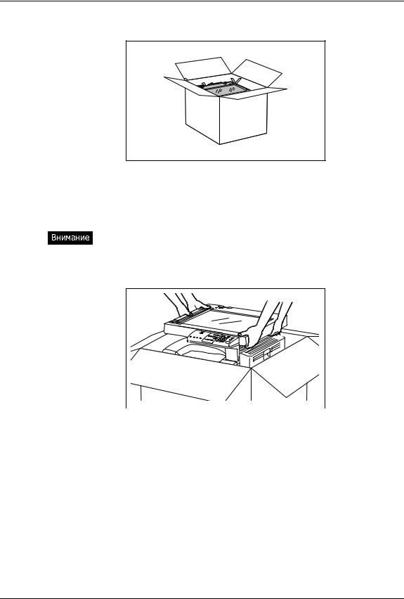
1 Откройте верхнюю сторону упаковки.
2 Взявшись вдвоем, так как показано на рисунке, достаньте аппарат из коробки и поставьте его на стол. Если на аппарате надеты синие ленты, используйте их для извлечения аппарата.
Избегайте подъема аппарата за левый передний угол, так как это может привести к деформации конструкции сканирующей системы.
РАСПАКОВКА И ЗАПУСК 1
|
3 |
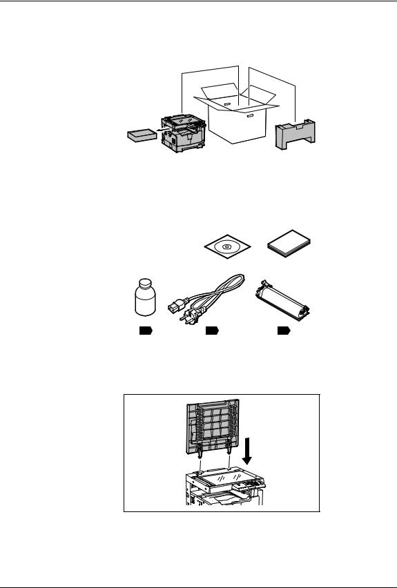
Извлеките из аппарата и из коробки картонные контейнеры с |
|||||||
|
аксессуарами. |
||||||||
4 Убедитесь, что все позиции, показанные на рисунке, имеются в наличии.
5 Снимите с крышки пластиковый пакет и вставьте ее в аппарат в открытом положении.
2 РАСПАКОВКА И ЗАПУСК
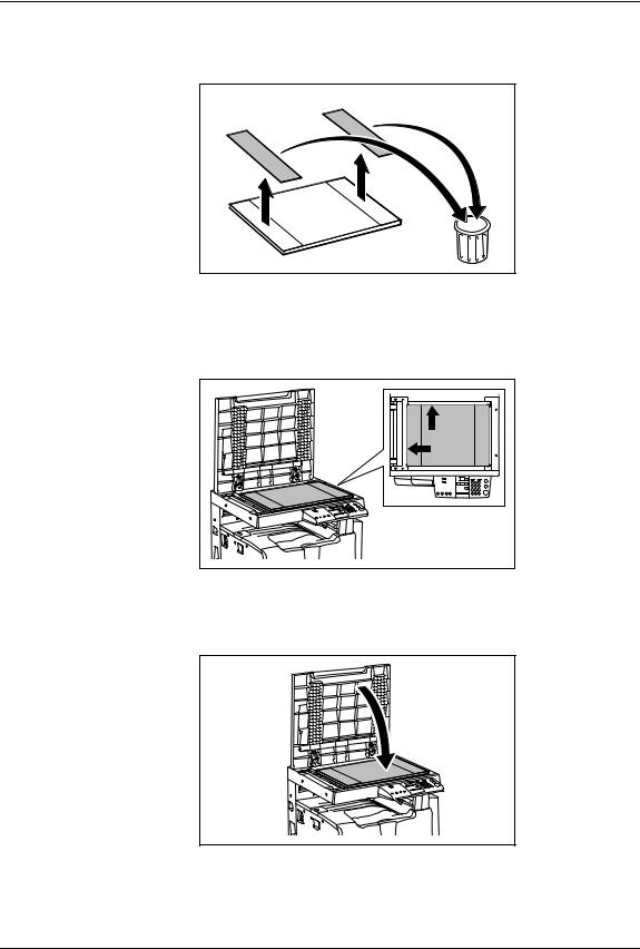
6 Удалите с поджимного листа две бумажные полосы, защищающие клейкие поверхности.
7 Положите поджимной лист на стекло оригинала и выровняйте его по линейкам оригинала, упирая в задний левый угол.
8 Аккуратно закройте крышку оригинала и слегка прижмите ее в местах клейких поверхностей.
РАСПАКОВКА И ЗАПУСК 3
|
9 |
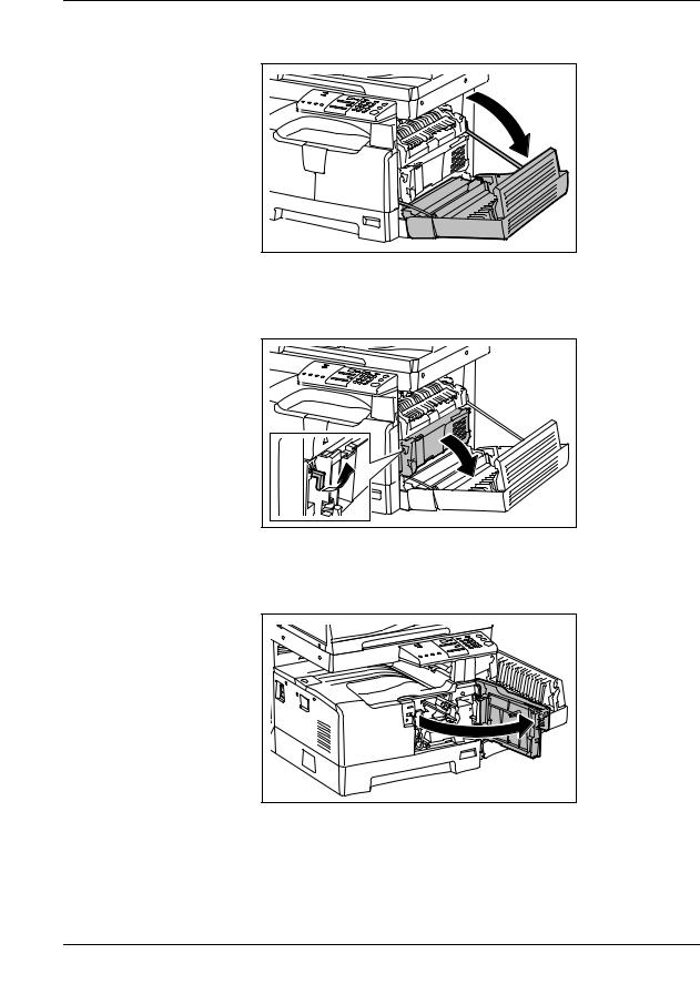
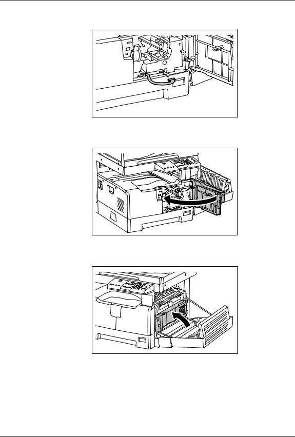
Потяните за ручку и откройте боковую крышку. |
|
10 |
Потяните за зеленый рычажок и откройте черную |
|
внутреннюю крышку. |
11 Потяните за выступ над серебристой вставкой e0STUDIO и откройте переднюю крышку.
4 РАСПАКОВКА И ЗАПУСК
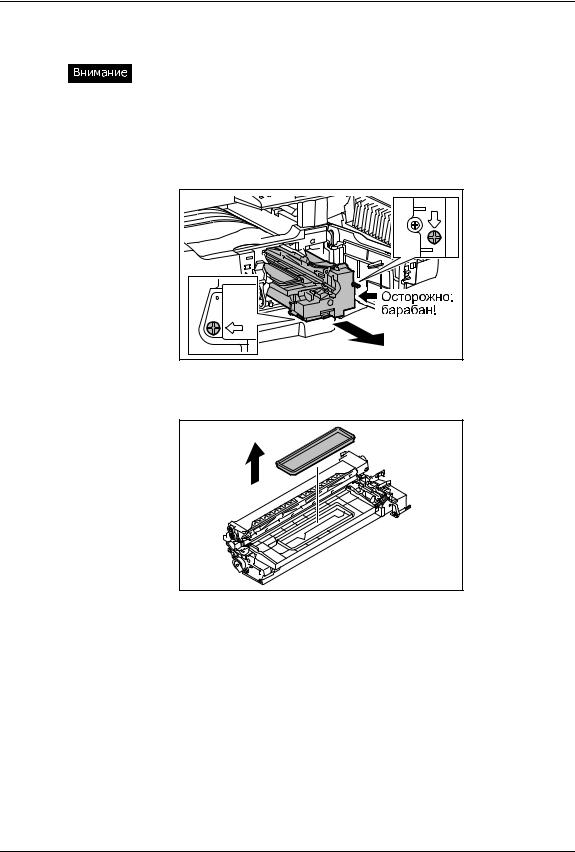
12 Выверните два длинных винта и аккуратно достаньте блок обработки из аппарата.
«Царапины и отпечатки пальцев на поверхности зеленого барабана будут оставлять грязные отметины на всех копиях, поэтому избегайте прикосновений к барабану.
«На свету характеристики барабана ухудшаются, поэтому не оставляйте блок обработки вне аппарата на длительное время или прикройте его светонепроницаемым материалом.
13 Снимите крышку с блока обработки.
РАСПАКОВКА И ЗАПУСК 5
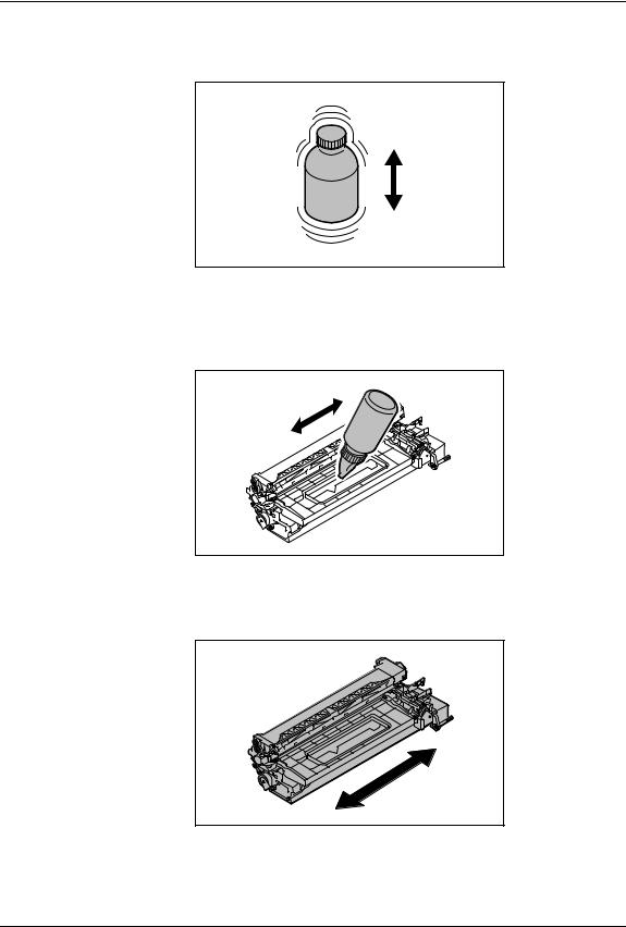
14 Потрясите бутылку с девелопером, чтобы разрыхлить слежавшийся порошок.
15 Равномерно по всей длине отверстия засыпьте девелопер в блок обработки. Постарайтесь, чтобы весь девелопер из бутылки попал внутрь блока.
16 Слегка потрясите блок обработки в направлении, указанном стрелкой, чтобы распределить девелопер внутри блока.
6 РАСПАКОВКА И ЗАПУСК
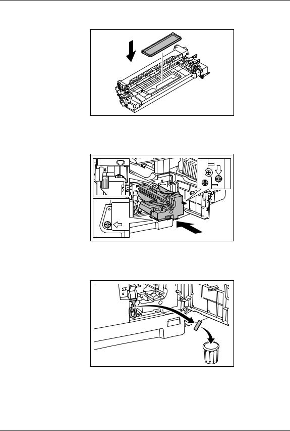
17 Установите крышку блока обработки на место.
18 Аккуратно установите блок обработки в аппарат и закрутите два длинных винта.
19 Удалите транспортировочную ленту с кабеля блока обработки.
РАСПАКОВКА И ЗАПУСК 7
|
20 |
Подключите кабель к разъему блока обработки. |
|
21 |
Закройте переднюю крышку. |
22 Закройте черную внутреннюю крышку.
8 РАСПАКОВКА И ЗАПУСК
![]()
|
23 |
Закройте боковую крышку. |
|
24 |
Подключите аппарат к розетке электропитания 220В и не |
|
менее 7А. |
25 Включите питание, используя выключатель, находящийся под крышечкой с левой стороны аппарата.
РАСПАКОВКА И ЗАПУСК 9
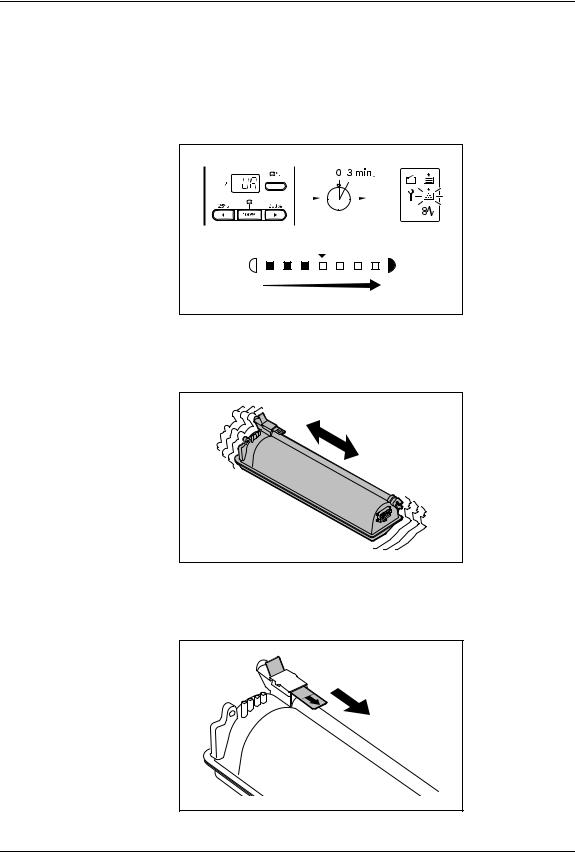
26 Аппарат автоматически выполнит процедуру самонастройки. Процесс выполнения процедуры сопровождается светодиодной индикацией на панели управления с дальнейшим изменением числового значения на дисплее. После завершения процедуры начнет мигать индикатор «Добавьте тонер».
27 Потряситепорошок. тубу с тонером, чтобы разрыхлить слежавшийся
28 Держа тубу так, как показано на рисунке, медленно удалите герметезирующую пленку.
10 РАСПАКОВКА И ЗАПУСК
|
29 |
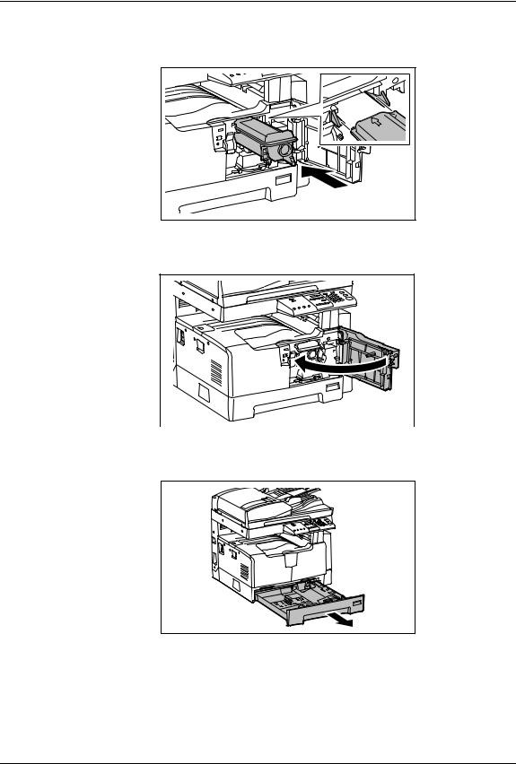
Вставьте тубу в аппарат по направляющим. Когда туба |
|
встанет на место, вы услышите щелчек. |
|
|
30 |
Закройте переднюю крышку. |
31 Слегка приподняв, выдвиньте кассету из аппарата.
РАСПАКОВКА И ЗАПУСК 11
|
32 |
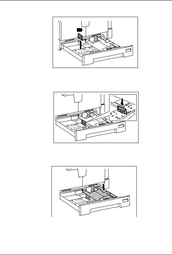
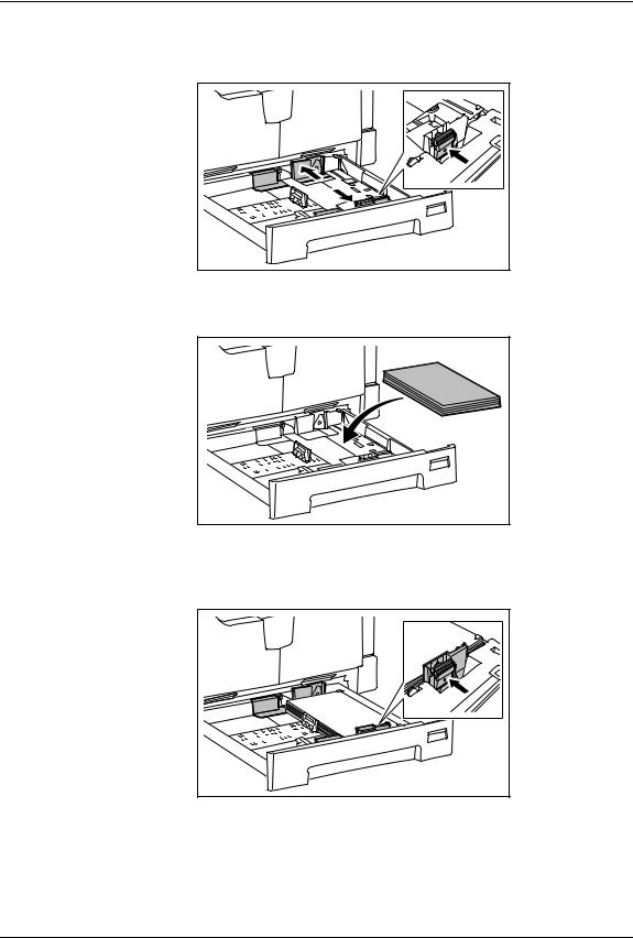
Достаньте зеленый ограничитель. |
|
34 |
|
|
33 |
Установите ограничитель в положение, соответствующее |
|
используемому формату бумаги. |
34 Опустите металлическое основание до фиксации в нижнем положении.
12 РАСПАКОВКА И ЗАПУСК
|
35 |
Нажав на зеленый фиксатор, раздвиньте боковые |
|
направляющие до краев кассеты. |
|
|
36 |
Положите в кассету не более 250 листов бумаги. |
37 Нажав на зеленый фиксатор, сдвиньте боковые направляющие по формату загруженной бумаги.
РАСПАКОВКА И ЗАПУСК 13
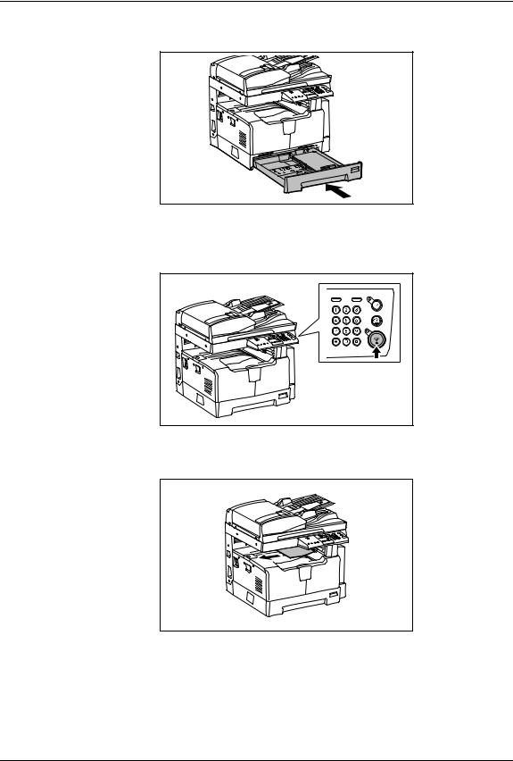
38 Задвиньте кассету в аппарат до упора.
39 Положите оригинал на стекло лицевой стороной вниз и нажмите на кнопку СТАРТ.
40 Проверьте полученную копию. Аппарат готов к работе.
14 РАСПАКОВКА И ЗАПУСК

Введение
Благодарим за покупку многофункциональной цифровой системы TOSHIBA. Мы подготовили для вас это руководство по работе на этом оборудовании.
В этом руководстве по эксплуатации описывается:
yКак пользоваться этим оборудованием
yКак проводить осмотр и техническое обслуживание этого устройства
yКак устранять механические неисправности и неполадки копирования
Перед тем, как начать работать с этим оборудованием, убедитесь, что вы прочитали это руководство. Держите это руководство под рукой в качестве справочника в будущем.
Введение 1

Информация для пользователей
После выбора подходящего места для установки e-STUDIO181/211, пожалуйста, не меняйте его. Избегайте избыточного нагрева, запыленности, вибраций и воздействия прямого солнечного света. Также обеспечьте надлежащую вентиляцию, так как копирующее устройство выделяет небольшое количество озона.
Это устройство классифицируется как лазерный продукт класса 1 в соответствии с
IEC 60825-1:1993/EN 60825-1.1994, включая поправки.
В этом устройстве используется лазерный диод с выходной мощностью 5 мВт с непрерывным излучением, длина волны 785 нм.
Осторожно:
Использование иных регулировок или управления, либо иное выполнение операции, чем определено здесь, может привести к опасному лучевому воздействию.
Внимание:
Это изделие относится к классу А. В домашних условиях оно может стать источником радиопомех, для устранения которых потребуется принять соответствующие меры.
Только для ЕС
Условия работы
Согласно требованиям электромагнитной совместимости, использование этого устройства ограничено в следующих местах:
yМедицинские учреждения: это изделие не сертифицировано в качестве изделия для использования в медицине в соответствии с директивой по медицинскому оборудованию
93/42/EEC
yЖилые помещения (например, жилые комнаты с радиоприемниками и телевизорами, расположенными неподалеку от этого изделия), потому что это изделие относится к классу А. В домашних условиях оно может стать источником радиопомех, для устранения которых потребуется принять соответствующие меры
Любые последствия применения этого изделия в условиях, не одобренных или указанных как непригодные для применения, не приводят к какой-либо ответственности компании TOSHIBA TEC.
При использовании этого продукта в таких условиях возможно возникновение электромагнитных помех у других устройств или установок, расположенных в непосредственной близости. В результате электромагнитных помех возможно нарушение работоспособности, включая утерю или повреждение данных в этом изделии или других устройствах и установках.
Помимо этого из общих соображений техники безопасности не разрешается использование настоящего изделия во взрывоопасных атмосферах.
Соответствие директивам ЕС
В соответствии с положениями применимых к этому изделию и соответствующим дополнительным приспособлениям Директив ЕС, в частности Директивы по низковольтному оборудованию 2006/95/EEC и Директивы по электромагнитной совместимости 2004/108/EEC, на этом устройстве имеется значок CE.
За эту маркировку несет ответственность компания СЕ TOSHIBA TEC GERMANY IMAGING SYSTEMS GmbH, Carl-Schurz-Str. 7, 41460 Neuss, Германия, телефон +49-(0)-2131-1245-0.
Для получения копии декларации соответствия свяжитесь со своим продавцом или компанией
TOSHIBA TEC.
2 Информация для пользователей
Только для Германии
Сведения об уровне шума устройства
Предписание 3. GPSGV: Максимальный уровень звукового давления равен или меньше 70 дБ(A)
согласно EN ISO 7779.
Только для ЕС
Следующая информация предназначена только для государств – членов ЕС:
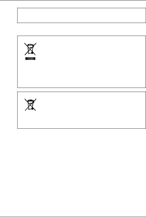
Это изделие маркировано в соответствии с требованиями директивы ЕС 2002/96/EC
(Директива по утилизации электрического и электронного оборудования — WEEE)
Использование этого символа указывает, что не разрешается утилизация данного изделия на муниципальных свалках без предварительной сортировки компонентов изделия. Обеспечив надлежащую утилизацию этого изделия, вы поможете предотвратить потенциальные негативные последствия для окружающей среды и здоровья людей, которые могли бы возникнуть в случае неправильной утилизации этого изделия.
Детальные сведения о возврате и повторной переработке этого изделия можно получить у поставщика, у которого оно было приобретено.
Следующая информация предназначена только для государств – членов ЕС:
Утилизация батарей или аккумуляторов (на основании Директивы ЕС 2006/66/EC,
Директивы по батареям и аккумуляторов и утилизации батарей и аккумуляторов)
Использование этого символа указывает, что не разрешается утилизация батарей и аккумуляторов на муниципальных свалках без предварительной сортировки компонентов изделия.
Детальные сведения о возврате и повторной переработке батарей или аккумуляторов можно получить у поставщика, у которого они были приобретены.
Информация для пользователей 3

Перед прочтением настоящего руководства
Чтобы прочитать руководства в формате PDF
Данное руководство представлено в формате файла PDF (Portable Document Format), находящееся на компакт-диске документации. Для просмотра и вывода на печать руководства по эксплуатации в формате PDF можно использовать программы Adobe Reader или Adobe Acrobat Reader. Если ни одна из этих программ не установлена на вашем компьютере, загрузите одну из них. Это можно выполнить с сайта Adobe Systems Incorporated.
Как читать это руководство Символы в настоящем руководстве
Для обеспечения правильного и безопасного использования оборудования, в настоящем руководстве описываются меры предосторожности следующих трех уровней. Необходимо внимательно изучить следующие предупреждающие обозначения и уяснить их значение и важность для прочтения настоящего руководства по эксплуатации.
Опасно !
Осторожно
Замечание
Обозначает потенциально опасную ситуацию, способную вызвать смерть или серьезную травму, либо привести к серьезному повреждению или возгоранию этого устройства или окружающего имущества.
Обозначает потенциально опасную ситуацию, способную вызвать легкие или средние травмы, либо привести к частичному повреждению устройства или окружающего имущества, или к потере данных.
Обозначает процедуру, которой необходимо следовать для обеспечения работы этого оборудования.
Кроме вышеупомянутого, в данном руководстве также приводится информация, которая может быть полезна для работы с этим оборудованием, со следующим идентификатором:
Описывает полезные сведения, помогающие в работе с оборудованием.
Совет
Ссылки на страницы руководства для получения дополнительной информации. Обратитесь к указанным разделам при необходимости.
4 Перед прочтением настоящего руководства
![]()
Ориентация оригинала/копии
Оригинал размера А4 может быть размещен в книжной или в альбомной ориентации. В настоящем руководстве в случае, когда оригинал или копия могут располагаться в альбомной ориентации, к размеру бумаги добавляется символ “-R”.
Например, оригинал формата А4 при размещении на стекле
|
Оригинал в книжной ориентации: A4 |
Оригинал в альбомной ориентации : A4-R |
Оригинал размера А3 или B4 может быть размещен только в альбомной ориентации, таким образом «-R» не добавляется к этим размерам.
Товарные знаки
yMicrosoft, Windows,Windows NT, а так же фирменный знак и наименование изделий — это товарные знаки Microsoft Corporation в США и других странах.
yAdobe, Adobe Acrobat, Adobe Reader, Adobe Acrobat Reader и PostScript — это товарные знаки компании Adobe Systems Incorporated.
yДругие компании или наименования изделий, приводимые в этом руководстве, могут быть фирменным знаком или торговой маркой каждой компании.
©2009 TOSHIBA TEC CORPORATION Все права защищены
Согласно законам об авторском праве, это руководство не может быть воспроизведено ни в какой форме без предварительного письменного разрешения корпорации TOSHIBA TEC. Однако относительно использования информации, содержащейся здесь, не предполагается никаких ограничений.
Перед прочтением настоящего руководства 5

ОГЛАВЛЕНИЕ |
||
|
Введение………………………………………………………………………………………… |
1 |
|
|
Информация для пользователей…………………………………………………… |
2 |
|
|
Перед прочтением настоящего руководства…………………………………. |
4 |
|
|
Непревзойденное качество TOSHIBA …………………………………………… |
11 |
|
|
Общие меры предосторожности ………………………………………………….. |
14 |
|
|
Уведомление об отказе от ответственности………………………………… |
19 |
|
|
Сведения об окружающей среде………………………………………………….. |
20 |
|
|
Глава 1 |
ПОДГОТОВКА |
|
|
Описание компонентов ………………………………………………………………… |
22 |
|
|
Передняя/правая сторона…………………………………………………………… |
22 |
|
|
Левая/внутренняя стороны…………………………………………………………. |
23 |
|
|
Конфигурация дополнительных приспособлений…………………………. |
25 |
|
|
Панель управления……………………………………………………………………. |
26 |
|
|
Подготовка 1 — Включение питания………………………………………………. |
29 |
|
|
Включение питания ……………………………………………………………………. |
29 |
|
|
Экономия энергии при простое — Режим экономии энергии -…………. |
30 |
|
|
Подготовка 2 — Размещение бумаги для копирования………………….. |
32 |
|
|
Допустимые типы бумаги……………………………………………………………. |
32 |
|
|
Рекомендованная бумага …………………………………………………………… |
33 |
|
|
Укладка бумаги в кассеты…………………………………………………………… |
34 |
|
|
Подготовка 3 — Регистрация размера бумаги………………………………… |
38 |
|
|
Регистрация бумаги стандартного размера (A3, A4, A4-R, A5-R, B4)38 |
||
|
Регистрация иных размеров стандартной бумаги………………………… |
39 |
|
|
Глава 2 |
КАК ДЕЛАТЬ КОПИИ |
|
|
Размещение оригиналов………………………………………………………………. |
42 |
|
|
Допустимые оригиналы………………………………………………………………. |
42 |
|
|
Размещение оригиналов на стекле…………………………………………….. |
43 |
|
|
Размещение оригиналов-буклетов, таких как книги или каталоги….. |
44 |
|
|
Использование автоподатчика документов (доп. оборудование) ….. |
45 |
|
|
Размещение оригиналов в автоподатчике документов (доп. |
||
|
оборудование) …………………………………………………………………………… |
46 |
|
|
Копирование страниц…………………………………………………………………… |
47 |
|
|
Остановка/возобновление копирования………………………………………. |
48 |
|
|
Прерывание копирования и запуск нового -…………………………………. |
49 |
|
|
Использование ручного лотка……………………………………………………… |
50 |
|
|
Подготовка – Регистрация размера бумаги, находящейся на ручном |
||
|
лотке…………………………………………………………………………………………. |
51 |
ОГЛАВЛЕНИЕ 7

|
Копирование с ручного лотка на бумагу стандартного размера ……. |
54 |
|
|
Глава 3 |
ФУНКЦИИ КОПИРОВАНИЯ |
|
|
Настройки по умолчанию……………………………………………………………… |
58 |
|
|
Выбор бумаги……………………………………………………………………………….. |
59 |
|
|
Автоматический выбор формата (АВФ)……………………………………….. |
59 |
|
|
Ручной выбор бумаги…………………………………………………………………. |
60 |
|
|
Увеличение/уменьшение копируемого изображения…………………… |
62 |
|
|
Автоматический выбор масштаба (АВМ)……………………………………… |
62 |
|
|
Задание размеров оригинала и копии…………………………………………. |
64 |
|
|
Задание масштаба вручную ……………………………………………………….. |
65 |
|
|
Копирование с сортировкой — ……………………………………………………… |
67 |
|
|
Копирование обеих сторон карты на одну страницу — КАРТА ID — .69 |
||
|
Выбор режима изображения………………………………………………………… |
71 |
|
|
Регулировка уровня плотности……………………………………………………. |
72 |
|
|
Глава 4 |
НАСТРОЙКА И РЕГУЛИРОВКА ОБОРУДОВАНИЯ |
|
|
Переключение режима включения/выключения звукового сигнала74 |
||
|
Проверка полного числа сделанных копий………………………………….. |
75 |
|
|
Изменение включенного режима экономии энергии……………………. |
76 |
|
|
Глава 5 |
ВЫЯВЛЕНИЕ И УСТРАНЕНИЕ НЕИСПРАВНОСТЕЙ |
|
|
Когда загорается или мигает индикатор сообщений……………………. |
78 |
|
|
Застрявшая бумага……………………………………………………………………….. |
81 |
|
|
Проверка положения застрявшей бумаги…………………………………….. |
81 |
|
|
Застрявшая бумага в автоподатчике документов (нижнем) (доп. |
||
|
оборудование) …………………………………………………………………………… |
82 |
|
|
Застрявшая бумага в автоподатчике документов (верхнем) (доп. |
||
|
оборудование) …………………………………………………………………………… |
84 |
|
|
Застрявшая бумага в ручном лотке…………………………………………….. |
86 |
|
|
Застрявшая бумага за узлом переноса……………………………………….. |
87 |
|
|
Застрявшая бумага в термозакрепляющем устройстве………………… |
88 |
|
|
Застрявшая бумага в бумагопротяжном устройстве (дополнительное |
||
|
оборудование) …………………………………………………………………………… |
90 |
|
|
Замена картриджа…………………………………………………………………………. |
91 |
|
|
Перед вызовом технической поддержки……………………………………… |
96 |
|
|
Общие операции………………………………………………………………………… |
96 |
8 ОГЛАВЛЕНИЕ

|
Позиции, относящиеся к тонеру………………………………………………….. |
97 |
|
Позиции, относящиеся к бумаге оригинала/копии………………………… |
98 |
|
Дефекты изображения……………………………………………………………….. |
98 |
|
Глава 6 ТЕХНИЧЕСКОЕ ОБСЛУЖИВАНИЕ И ОСМОТР |
|
|
Ежедневный осмотр …………………………………………………………………… |
102 |
|
Чистка коротрона……………………………………………………………………… |
103 |
|
Чистка проволки коротрона ………………………………………………………. |
104 |
Глава 7 ТЕХНИЧЕСКИЕ ХАРАКТЕРИСТИКИ И ДОПОЛНИТЕЛЬНОЕ ОБОРУДОВАНИЕ
|
Технические характеристики e-STUDIO181/211 ………………………….. |
108 |
|
Скорость копирования в непрерывном режиме………………………….. |
109 |
|
Упаковочный лист…………………………………………………………………….. |
109 |
|
Технические характеристики дополнительных приспособлений 110 |
|
|
УКАЗАТЕЛЬ…………………………………………………………………………………………………………….. |
111 |
ОГЛАВЛЕНИЕ 9

10 ОГЛАВЛЕНИЕ
Картридж |
|
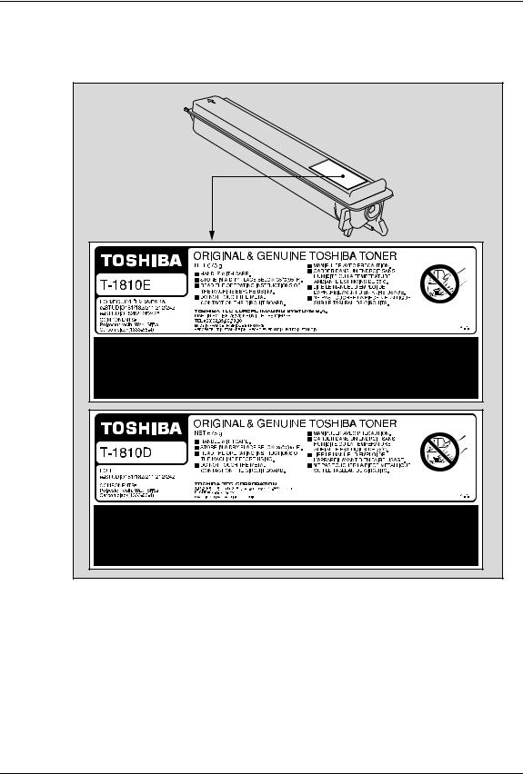
Для получения наилучших отпечатков, мы рекомендуем использовать только |
|
оригинальные картриджи TOSHIBA. |
|
При использовании картриджей, рекомендованных компанией TOSHIBA, вы можете |
|
воспользоваться следующими тремя функциями данной машины: |
Функция проверки наличия картриджа:
Проверяет, правильно ли установлен картридж, и уведомляет вас в случае ошибки.
Функция проверки наличия тонера
Уведомляет вас в случае, если в картридже заканчивается тонер.
Непревзойденное качество TOSHIBA 11

Функция оптимизации качества изображения:
Эта функция управляет соответствующим качеством изображения в соответствии с характеристиками тонера, что позволяет применить распечатки изображения с оптимальным качеством.
При использовании картриджа, отличного от рекомендованного, машина не сможет определить, установлен картридж или нет. Даже если тонер установлен правильно, индикаторы тонера горят или мигают и печать может быть запрещена. Также вы можете настроить функции качества изображения и проверки оставшегося тонера.
Если вас раздражает это сообщение при использовании картриджа, отличного от рекомендованного, свяжитесь с уполномоченным представителем сервисной службы. По умолчанию функция проверки наличия картриджа может быть отключена. Но помните, что отключив проверку наличия картриджа, вы не сможете пользоваться тремя этими функциями, упомянутыми выше, даже если вы будете использовать рекомендованный корпорацией TOSHIBA картридж
Расходные материалы и запасные части
Надежность
Оригинальные расходные материалы TOSHIBA проходят строжайшую проверку, поэтому все они соответствуют высоким уровням качества.
Высокая производительность
Оригинальные расходные материалы TOSHIBA создавались в ответ на потребности нашего наполненного конкуренцией мира и обеспечивают высокоскоростное получение копий по вашему требованию без всяких проблем.
Стабильное качество изображения
Оригинальные расходные материалы TOSHIBA предназначены для обеспечения неизменно стабильного вывода изображений.
Удобство использования расходных материалов для копира
Оригинальные расходные материалы TOSHIBA разработаны с целью поддержания устройства и всех его деталей в отличном рабочем состоянии. Благодаря уменьшению износа, обеспечиваемому глубокими знаниями компанией TOSHIBA всех характеристик устройства, гарантируется наивысший стандарт ухода за изделием.
Идеально подходящие расходные материалы
С самого начала расходные материалы и устройства TOSHIBA разрабатываются друг для друга. При разработке нового устройства компания TOSHIBA также создает и новый тонер для него. При использовании оригинальных расходных материалов TOSHIBA с продукцией TOSHIBA гарантируются оптимальные характеристики.
Тонер
Оптимальное качество изображения
Тонер TOSHIBA производится с использованием высококачественных сверхтонких материалов в условиях жесткого контроля; а это гарантирует, что ваше копирующее устройство TOSHIBA будет неизменно создавать четкие высококачественные изображения.
12 Непревзойденное качество TOSHIBA

Преимущество по цене
Оригинальный тонер Toshiba снижает издержки. При воспроизведении используется только необходимое количество тонера, в результате чего устройство продолжает работать до самого полного использования тонера. Так вы снижаете издержки использования каждого картриджа.
Гармония с окружающей средой
Оригинальный тонер Toshiba изготавливается с учетом требований минимального воздействия на окружающую среду. На каждом картридже мы помещаем тисненые или наклеиваемые метки, указывающие, что он может повторно использоваться. Помимо этого, для улучшения рабочих условий были значительно снижены допустимые уровни опасной для здоровья пыли и озона.
Удобство для пользователя
Перед выпуском тонера в продажу мы проверяем его, чтобы убедиться, что он соответствует строжайшим гигиеническим стандартам. Поэтому работать с ним можно без опаски.
Общие сведения
О пользе обслуживания и поддержки
Технические специалисты TOSHIBA проходят сертификацию, что позволяет им поддерживать состояние вашего оборудования на оптимальном уровне. Чтобы гарантировать неизменно высокое качества изображения, используйте для проведения периодического обслуживания вашего копировального аппарата службу технической поддержки Toshiba.
Непревзойденное качество TOSHIBA 13

Общие меры предосторожности
При установке или перемещении
Опасно
yЭто устройство требует питание 220-240 В, 8 А, 50/60 Гц. В исполнении на 100 В для Саудовской Аравии необходимо питание 127 В, 12 А, 50/60 Гц.
Не используйте источники питания с другим напряжением.
Не подключайте несколько устройств к одной розетке. Это может привести к пожару или поражению электрическим током. Если вы решите увеличить количество розеток, обратитесь к электрикам.
yВо избежание пожара или поражения электрическим током в случае пробоя на корпус всегда подключайте эту систему к розетке с заземлением. Обратитесь в службу технической поддержки за консультацией. Убедитесь, что используется 3-проводная заземленная розетка.
Там, где используются 2-контактные разъемы, для обеспечения безопасной работы эти системы необходимо заземлять. Никогда не используйте в качестве заземления газовые, водопроводные трубы и любые другие не предназначенные для этого объекты.
yПлотно вставьте шнур питания в розетку. Плохой контакт может нагреваться и привести к пожару или поражению электрическим током.
yНе повреждайте, не обрывайте и не пытайтесь починить шнур питания. Следует избегать следующего обращения со шнуром питания.
—скручивания
—перегибания
—вытягивания
—установки на него каких-либо предметов
—нагрева
—размещения вблизи него нагревательных приборов.
Это может привести к пожару или поражению электрическим током. Если шнур питания поврежден, обратитесь в службу технической поддержки.
yНе пытайтесь самостоятельно установить устройство или поменять место установки. Это может привести к травме или повреждению устройства. В случае, если необходимо установить или переместить устройство, свяжитесь с представителем сервисной службы.
yНе реже одного раза в год вынимайте вилку из розетки для очистки контактов. Накопление пыли и грязи может привести к пожару из-за нагрева, вызванного утечкой тока.
14 Общие меры предосторожности
![]()
Осторожно
yНе допускайте размещения устройства на поверхности, не способной выдержать его вес, а также убедитесь, что поверхность горизонтальна.
Помните, что при падении устройства возможны серьезные травмы. Вес оборудования: около 32,9 кг (для ЕС), около 31,8 кг (помимо ЕС)
yВынимая вилку из розетки, не тяните за шнур питания. Всегда держитесь за вилку, вынимая ее из розетки. Если тянуть за шнур питания, провода могут порваться, что может привести к пожару или поражению электрическим током.
yУбедитесь, что вентиляционные отверстия открыты.
При значительном повышении температуры внутри системы может возникнуть пожар.
Прочие рекомендации
yСетевая розетка должна находиться вблизи устройства и быть легко доступной.
yУбедитесь, что вокруг устройства достаточно места для облегчения замены деталей и обслуживания и удаления застрявшей бумаги.
Если места недостаточно, некоторые операции, такие как подача с ручного лотка, становятся трудно выполнимыми, а система может выйти из строя.
Для оптимальной работы, очистите пространство как минимум на 80 сантиметров справа и по 10 сантиметров слева и спереди устройства.
10 см
10 см
80 см
yУбедитесь, что кабель надежно закреплен так, что по нему никто не может пройти.
yНеблагоприятные внешние условия могут влиять на безопасность работы и характеристики этого устройства, а оно само даже может выйти из строя.
—Избегайте размещения вблизи окна или под прямыми солнечными лучами.
—Избегайте размещения в местах со значительными перепадами температуры.
—Избегайте запыленных мест.
—Избегайте мест с повышенной вибрацией.
yУбедитесь, что воздух проходит свободно и имеется достаточно вентиляции. Без надлежащей вентиляции в воздухе помещения появится неприятный запах, вызванный выделением озона.
Общие меры предосторожности 15

При использовании устройства
Опасно
yНе открывайте корпус оборудования; это может привести к травме или поражению электрическим током.
yНе вставляйте и не вынимайте вилку шнура питания из розетки мокрыми руками, так как вы можете получить поражение электрическим током.
yНе кладите емкости с водой (вазы с цветами, чашки с кофе и т. д.) на устройство или поблизости от него. Это может привести к пожару или поражению электрическим током.
yДержите скрепки для бумаги подальше от вентиляционных отверстий. Это может привести к пожару или поражению электрическим током.
yЕсли система слишком нагрелась, появились дым, странный запах или шум, выполните следующее.
Выключите питание, выньте вилку шнура из розетки и обратитесь в службу технической поддержки.
yЕсли устройство не будет использоваться в течение ближайшего месяца, на это время выньте вилку шнура питания из розетки в целях безопасности.
Если произойдет пробой изоляции, может возникнуть пожар или поражение электрическим током.
Осторожно
yНе кладите тяжелые предметы (тяжелее 4 кг) на стекло и не давите на него. Если стекло лопнет, вы можете получить травму.
yНе кладите тяжелые предметы (тяжелее 4 кг) на устройство. Если они упадут, вы можете получить травму.
yБерегите пальцы, закрывая лоток. Вы можете их прищемить.
yНе прикасайтесь к печке или металлическим деталям вокруг нее. Поскольку они очень горячие, вы можете обжечься, а рефлекторные движения могут привести к повреждению рук о внутренние детали устройства.
yНе засовывайте пальцы между устройством и боковой крышкой. Вы можете их прищемить.
yНе прикасайтесь к соединительной детали на задней стороне автоподатчика документов (дополнительное оборудование). Вы можете защемить и поранить пальцы открывая или закрывая автоподатчик документов (дополнительное оборудование).
16 Общие меры предосторожности

Расположение сертификационных табличек и т. д.
Поясняющая табличка
Идентификационая табличка
For EU
Except for EU
Предупреждающая табличка
|
Предупреждение для областей с высокой температурой (вентиляционные отверстия) |
|
Предупреждение для областей с высокой температурой (печка) |
Общие меры предосторожности 17

Прочие рекомендации
yНе выключайте питания, если внутри устройства осталась застрявшая бумага. Это может привести к неисправностям при следующем включении питания.
yУбедитесь, что питание выключено, когда вы покидаете офис, или если имеются отказы питания.
yБудьте осторожны, поскольку выходной тракт и бумага в нем непосредственно после выхода имеют высокую температуру.
yНе кладите на приемный лоток ничего, кроме бумаги. Это может нарушить нормальную работу устройства и привести к поломкам.
yНе прикасайтесь к поверхностям барабана и коротрона. Это может привести к проблемам с изображением.
yВо время печати не открывайте и не закрывайте крышки и ручной лоток и не вытягивайте кассеты.
Во время профилактики и обслуживания
Опасно
yНикогда не пытайтесь самостоятельно разобрать или отремонтировать это устройство. Вы можете вызвать пожар или получить поражение электрическим током.
Для обслуживания или ремонта внутренних компонентов этого устройства всегда обращайтесь в службу технической поддержки.
yПри чистке полов не допускайте попадания внутрь устройства жидкостей, таких как вода и масло. Это может привести к пожару или поражению электрическим током.
Осторожно
yВсегда поддерживайте вилку шнура питания и розетку в чистом состоянии. Не допускайте накопления на них пыли и грязи. Это может привести к пожару или поражению электрическим током из-за нагрева, вызванного электрическими утечками.
Прочие рекомендации
yНе используйте для очистки поверхностей копировального аппарата растворители, такие как бензин или растворитель для лаков.
—Это может привести к деформации поверхности или изменению ее цвета.
—При использовании химических очищающих салфеток обращайте внимание на предупреждения производителя.
При работе с расходными материалами
Опасно
yНикогда не пытайтесь сжечь картриджи. Это может привести к взрыву. Не выбрасывайте использованные картриджи. Свяжитесь с представителем сервисной службы.
18 Общие меры предосторожности

Уведомление об отказе от ответственности
Изложенное ниже относится к исключению и ограничению ответственности компании TOSHIBA TEC CORPORATION (включая ее работников, агентов и субподрядчиков) перед любым покупателем или пользователем («Пользователь») устройства e-STUDIO181/211, включая и относящиеся к нему аксессуары, дополнительные устройства и входящее в комплект программное обеспечение («Продукт»).
1Исключение и ограничение ответственности, относящиеся к этому уведомлению, действительны в максимально разрешенной действующим законодательством степени. Во избежание недоразумений, ни какая часть этого уведомления не может быть изъята, чтобы исключить или ограничить ответственность компании TOSHIBA TEC за смерть или телесные повреждения, вызванные небрежностью компании TOSHIBA TEC или намеренными искажениями информации, предоставляемой компанией TOSHIBA TEC.
2.Все гарантии, условия и другие положения, вытекающие из предписаний закона, исключены в максимально разрешенной действующим законодательством степени, и никакие подразумеваемые гарантии не даются или не применяются в отношении данного Продукта.
3.Компания TOSHIBA TEC не несет ответственности за любые потери, убытки, затраты, претензии или ущерб, вызванные чем-либо из нижеследующего:
(a)использование или обращение с Продуктом иными способами, чем описанные в руководствах, в частности, в руководстве по эксплуатации, руководстве пользователя, или же неправильное или небрежное обращение или использование Продукта;
(b)любые причины, препятствующие правильной эксплуатации или функционированию Продукта, которые проистекают или же могут быть приписаны любым действиям, упущениям, событиям или несчастным случаям, находящимися за пределами приемлемого контроля компании TOSHIBA TEC, включая, в частности действие непреодолимых обстоятельств, войну, восстание, гражданские волнения, злоумышленное или преднамеренное повреждение, пожар, наводнение, ураган, стихийное бедствие, землетрясение, напряжение питания, выходящее за нормальные значения, или другие катастрофы;
(c)добавление, модернизация, разборка, перемещение или ремонт любыми лицами, кроме сервисных инженеров, уполномоченных компанией TOSHIBA TEC CORPORATION; или:
(d)использование бумаги, расходных материалов или запчастей, отличных от рекомендованных компанией TOSHIBA TEC.
Уведомление об отказе от ответственности 19

4.При условии применимости п.1 компания TOSHIBA TEC не несет ответственности перед Клиентом за:
(a)утрату прибыли, снижение продаж или оборота, нанесенные репутации, утрату продукции, отсутствие ожидаемой экономии, потерю нематериальных активов или возможностей для развития бизнеса, потеря клиентов, утрату или невозможность использования любого программного обеспечения или данных, потери, понесенные по любому контракту или в связи с ним, или:
(b)любые дополнительные, случайные, сопутствующие или косвенные потери, убытки, затраты, расходы, финансовые потери или претензии на компенсацию;
каким бы то ни было образом связанные или возникающие в связи с настоящим Продуктом или же с использованием или обращением с данным Продуктом, даже если компания TOSHIBA TEC и осведомлена возможностью такового ущерба.
Компания TOSHIBA TEC CORPORATION не несет ответственности ни за какие убытки, затраты, расходы, претензии или ущерб, вызванные неспособностью использования (включая, в частности, неисправность, неправильное функционирование, зависание, инфицирование вирусами или другие проблемы), возникающие в результате использования данного Продукта с оборудованием, предметами или программным обеспечением, которые компания TOSHIBA TEC CORPORATION не поставляла ни непосредственно, ни косвенным образом.
20 Уведомление об отказе от ответственности

Сведения об окружающей среде
Программа ENERGY STAR®
Корпорация Toshiba Tec Corporation, являясь партнером программы ENERGY STAR, наносит логотип ENERGY STAR на все изделия, которые сответствуют стандартам программы ENERGY STAR.
Цель программы ENERGY STAR заключается в поощрении разработки и широкого использования офисного оборудования, включая энергосберегающие технологии для компьютеров, предназначенные для предотвращения загрязнения окружающей среды, связанного с глобальным потеплением. Производители, участвующие в этой программе, могут наносить логотип Energy Star на изделия после подтверждения соответствия со стандартами программы энергосберегающих технологий. Кроме того, эти стандарты и логотип обычно используются Управлением по охране окружающей среды США (EPA) и странами-участниками.
Конкретные продукты, страны или регионы
Чтобы определить, соответствует ли данный продукт требованиям программы ENERGY STAR, посмотрите, имеется ли на нем соответствующий логотип.
Если если вопросы, свяжитесь с представителем сервисной службы.
Особенности экономии энергии
В данном изделии использованы функции сохранения энергии, предназначеные для снижения потребления энергии.
Режим низкого питания
Устройство автоматически переходит в этот режим через заданное время *1 с момента последнего использования. В этом режиме на светодиодном дисплее появляется “ALP”.
Спящий режим / режим с минимальным потреблением энергии
Настоящее оборудование автоматически переходит в этот режим через заданное время *2
с момента последнего использования.*3 В этом режиме на светодиодном дисплее появляется “SLP”. В режиме с минимальным потреблением энергии светодиодный дисплей не горит.
*1 Если хотите изменить интервал при вводе в режим низкого питания, свяжитесь с технической службой.
*2 При вводе в спящий режим / режим с минимальным потреблением энергии можно изменить интервал.
С.76 “Изменение включенного режима экономии энергии” *3 Необходимые условия для отмены спящего режима / режима с минимальным потреблением
энергии см. следующую страницу:
С.30 “Отмена режима экономии энергии”
Сведения об окружающей среде 21

ПОДГОТОВКА
В этой главе описываются общие сведения, которые вы должны знать перед началом использования данного оборудования — как включить питание, как сделать копию и т.д.
|
Описание компонентов……………………………………………………………………………. |
22 |
|
Передняя/правая стороны……………………………………………………………………………………………….. |
22 |
|
Левая/внутренняя стороны………………………………………………………………………………………………. |
23 |
|
Конфигурация дополнительного оборудования…………………………………………………………………. |
25 |
|
Панель управления…………………………………………………………………………………………………………. |
26 |
|
Подготовка 1 — Включение питания …………………………………………………………. |
29 |
|
Включение питания…………………………………………………………………………………………………………. |
29 |
|
Экономия энергии при простое — Режим экономии энергии — ……………………………………………… |
30 |
|
Подготовка 2 — Размещение бумаги для копирования……………………………… |
32 |
|
Допустимые типы бумаги…………………………………………………………………………………………………. |
32 |
|
Рекомендованная бумага ………………………………………………………………………………………………… |
34 |
|
Укладка бумаги в кассеты………………………………………………………………………………………………… |
35 |
|
Подготовка 3 — Регистрация размера бумаги …………………………………………… |
39 |
|
Регистрация бумаги стандартного размера (A3, A4, A4-R, A5-R, B4) ………………………………….. |
39 |
|
Регистрация иных размеров стандартной бумаги……………………………………………………………… |
40 |

1 ПОДГОТОВКА
Описание компонентов
Передняя/правая стороны
3
10
9
8
6
7
1.Поджимной лист (дополнительное оборудование, KA-1650PC)
Поместите оригинал на стекло, закройте крышку и запустите операцию копирования. (В зависимости от машины, это уже может быть установлено.)
2.Автоподатчик документов (доп. оборудование, MR-2020)
При размещении оригиналов в автоподатчике, они автоматически сканируются поочередно. Максимум 100 листов оригиналов (или же стопка бумаги высотой до 16 мм) может быть помещено в автоподатчик документов.
(Максимальное число страниц зависит от типа носителя оригинала).
С.46 “Размещение оригиналов в автоподатчике документов (дополнительное оборудование)”
С.81 “Застрявшая бумага”
3.Карман для руководства оператора (сзади) (дополнительное оборудование, KK-1660)
Храните данное руководство по эксплуатации в этом кармане.
4.Боковая сторона
5.Ручной лоток
Используйте ручной лоток для копирования на особых типах носителей, таких как пленка для проекторов или калька.
С.50 “Использование ручного лотка” С.81 “Застрявшая бумага”
6.Крышка податчика бумаги (бумагопротяжного устройства (дополнительное оборудование)
7.Индикатор размера бумаги
22 Описание компонентов
![]()
8.Бумагопротяжное устройство (дополнительное оборудование, MY-1027)
Добавляет еще одну кассету для данного оборудования. Может быть загружено до 250 листов обычной бумаги.
9.Кассета
До 250 листов обычной бумаги может быть загружено в одну кассету.
10.Передняя крышка
Откройте эту крышку, когда заменяете картридж. С.91 “Замена картриджа”
Левая/внутренняя стороны
9
5
1.Стекло для размещения оригинала
Используйте при копировании трехмерных оригиналов, двустороннего копирования и специальных видов бумаги, таких как пленка для проекторов или калька, а также и для обычной бумаги.
С.42 “Размещение оригиналов”
2.Панель управления
Предназначена для запуска копирования, ввода числа копий и прочих параметров. С.26 “Панель управления”
3.Рекомендованные картриджи
С.11 “Картридж” С.91 “Замена картриджа”
4.Выключатель питания
Включает / Выключает питание оборудования. С.29 “Подготовка 1 — Включение питания”
Описание компонентов 23

1ПОДГОТОВКА
5.Ограничитель выходного тракта
Предназначен для предотвращения падения бумаги из выходного тракта. Откройте его, если вы делаете большое количество копий на бумагу большого размера (например А3, В4).
6.Разъем питания
Используется для подключения устройства при помощи прилагаемого шнура питания.
7.Разъем USB (4-контактный)
При помощи этого разъема вы можете подключить устройство к вашему компьютеру стандартным USB кабелем.
Замечания
yИспользуйте высокоскоростной интерфейс USB2.0 с сертифицированным кабелем: USB-кабель, поддерживающий высокоскоростной режим USB2.0 (скорость передачи 480 Мбит/с), сертифицированный в соответствии с USB Implementers Forum.
yПодключение этого устройства к компьютеру через USB-кабель. При подключении к компьютеру через USB-концентратор, это устройство не определяется.
8.Приемный лоток
9.Область сканирования
Здесь сканируются оригиналы, поданные при помощи автоподатчика документов (дополнительное оборудование, MR-2020).
С.102 “Ежедневный осмотр”
10.Линейка оригинала
Используйте линейку для проверки размера оригинала, размещенного на стекле.
11.Поджимной лист
С.102 “Ежедневный осмотр”
24 Описание компонентов
 Loading…
-
Руководства по ремонту
1
-
Инструкции по эксплуатации
1
Toshiba e-STUDIO181 инструкция по эксплуатации
(138 страниц)
- Языки:Русский
-
Тип:
PDF -
Размер:
5.55 MB -
Описание:
Многофункциональное устройство (МФУ)
Просмотр
На NoDevice можно скачать инструкцию по эксплуатации для Toshiba e-STUDIO181. Руководство пользователя необходимо для ознакомления с правилами установки и эксплуатации Toshiba e-STUDIO181. Инструкции по использованию помогут правильно настроить Toshiba e-STUDIO181, исправить ошибки и выявить неполадки.
Specifications:244/244826-estudio181.pdf file (25 Jan 2023) |
Accompanying Data:
Toshiba e-STUDIO181 All in One Printer, Speakers PDF Operator’s Manual (Updated: Wednesday 25th of January 2023 07:53:41 AM)
Rating: 4.8 (rated by 62 users)
Compatible devices: MJ-1027, 2500c, E-STUDIO151, TY-WSP200, e-STUDIO350, MJ-1028, E-studio 2050c, e-STUDIO6540C.
Recommended Documentation:
Text Version of Operator’s Manual
(Ocr-Read Summary of Contents of some pages of the Toshiba e-STUDIO181 Document (Main Content), UPD: 25 January 2023)
-
87, Replacing Toner Cartridge 85 Replacing Toner Cartridge When the toner in the toner cartridge has run out, replace the toner cartridge following the pro- cedure below. y Before inserting a new toner cartridge, check the product name of the cartridge. If you can see “T-1810”, this cartridge is usable.…
-
65, Copying Both Sides of Card into 1 Page — ID CARD — 63 Copying Both Sides of Card into 1 Page — ID CARD — The both sides of a card-sized original can be copied into one side of LT paper. This function is useful when you need to copy massive amounts of 2-sided cards. 1 Place paper in the drawer. …
-
4, Toshiba e-STUDIO181 2 Notice to Users Notice to Users FCC NOTICE This equipment has been tested and found to comply with the limits for a Class A digital device, pursuant to Part 15 of the FCC Rules. These limits are designed to provide reasonable protection against harmful interference when the equipment is operated in a commer…
-
29, Toshiba e-STUDIO181 Preparation 1 — Turning Power ON 27 Preparation 1 — Turning Power ON Turning power ON 1 Press the power switch to “ ” (ON) side. The equipment starts warming itself up. The warm-up time takes approx. 25 seconds. When the warm-up has finished, the [START] lamp is lit to show that the equipment is ready f…
-
32, 1 PREPARATION 30 Preparation 2 — Placing Copy Paper Preparation 2 — Placing Copy Paper Place copy paper in an appropriate paper source before you start copying. Acceptable media types Standard size plain paper (17 to 20 lb. Bond) can be used for the drawers in the equipment and the Paper Feed Unit (optional). Se…
-
Toshiba e-STUDIO181 User Manual
-
Toshiba e-STUDIO181 User Guide
-
Toshiba e-STUDIO181 PDF Manual
-
Toshiba e-STUDIO181 Owner’s Manuals
Recommended: HeatDish Plus, NV-DCF3 Series, TX-26LM70FA
-
Lexmark E260
Lexmark E260, E260d, andE260dn SeriesUser’s GuideMay 2008 www.lexmark.comLexmark and Lexmark with diamond design are trademarks of Lexmark International, Inc., registered in the United States and/or other countries.All other trademarks are the property of their respective owners.© 2008 Lexmark International, …
E260 156
-
Lexmark CX310 series
Quick ReferenceLearning about the printerUsing the printer control panel12345678910Use the To1 Display• View printing, copying, e‑mailing, andscanning options.• View printer status and error messages.2 Select button• Select menu options.• Save settings.3 Arrow buttons Scroll through menus or settings …
CX310 series 16
-
Konica Minolta bizhub 652
Copy OperationsUser’s GuideUser’s Guide*XXXXXXXX00**XXXXXXXX00*Konica Minolta Business Solutions Europe GmbHEuropaallee 17 30855 Langenhagen • GermanyTel.: +49 (0) 511 74 04-0Fax: +49 (0) 511 74 10 50www.konicaminolta.eu© 2009 Konica MinoltaBusiness Solutions Europe GmbHAll rights reserved. Pr …
bizhub 652 294
-
Kyocera TASKalfa 650c
6LH09633000 (1/4)2009.8305JN56811 According to the equipment model, these illustrations may differ from the appearances. 適用される機体のモデルによって、イラストと外観が異なることがあります。 Selon le modèle, il est possible que ces illustrations changent. Je nach Modell kön …
TASKalfa 650c 4
Additional Information:
Popular Right Now:
Operating Impressions, Questions and Answers:
Смотреть руководство для Toshiba e-studio 181 ниже. Все руководства на ManualsCat.com могут просматриваться абсолютно бесплатно. Нажав кнопку «Выбор языка» вы можете изменить язык руководства, которое хотите просмотреть.

MANUALSCAT | RU
Вопросы и ответы
У вас есть вопрос о Toshiba e-studio 181, но вы не можете найти ответ в пользовательском руководстве? Возможно, пользователи ManualsCat.com смогут помочь вам и ответят на ваш вопрос. Заполните форму ниже — и ваш вопрос будет отображаться под руководством для Toshiba e-studio 181. Пожалуйста, убедитесь, что вы опишите свои трудности с Toshiba e-studio 181 как можно более детально. Чем более детальным является ваш вопрос, тем более высоки шансы, что другой пользователь быстро ответит на него. Вам будет автоматически отправлено электронное письмо, чтобы проинформировать вас, когда кто-то из пользователей ответит на ваш вопрос.
Задать вопрос о Toshiba e-studio 181
- Бренд:
- Toshiba
- Продукт:
- принтеры
- Модель/название:
- e-studio 181
- Тип файла:
- Доступные языки:
- голландский
Сопутствующие товары Toshiba e-studio 181
![]()
SERVICE MANUAL
MULTIFUNCTIONAL DIGITAL SYSTEMS
e-STUDIO181/211
Model: DP-1810/2110
Publish Date: December 2009
File No. SMJ09001300
R091021I2400-TTEC
Ver00_2009-12

Trademarks
•The official name of Windows 95 is Microsoft Windows 95 Operating System.
•The official name of Windows 98 is Microsoft Windows 98 Operating System.
•The official name of Windows Me is Microsoft Windows Millennium Edition Operating System.
•The official name of Windows 2000 is Microsoft Windows 2000 Operating System.
•The official name of Windows XP is Microsoft Windows XP Operating System.
•Microsoft, Windows, Windows NT, Windows Vista and the brand names and product names of other Microsoft products are trademarks or registered trademarks of Microsoft Corporation in the U.S. and/or other countries.
•Apple, AppleTalk, Macintosh, and Mac are trademarks of Apple Computer, Inc. in the U.S. and other countries.
•PostScript is a trademark of Adobe Systems Incorporated.
•NOVELL, NetWare, and NDS are trademarks or registered trademarks of Novell, Inc.
•Mylar is a registered trademark of DuPont Teijin Films U.S. Limited Partnership.
•Molykote is a registered trademark of Dow Corning Corporation.
•FLOIL is a registrated treadmark of Kanto Kasei Ltd. CORPORATION.
•TopAccess is a trademark of Toshiba Tec Corporation.
•Felica is a trademark of Sony Corporation.
•iCLASS is a trademark of HID Corporation.
•MIFARE is a trademark of Royal Philips Electronics.
•Other company names and product names in this manual are the trademarks of their respective companies.
© 2009 TOSHIBA TEC CORPORATION All rights reserved
Under the copyright laws, this manual cannot be reproduced in any form without prior written permission of TOSHIBA TEC CORPORATION. No patent liability is assumed, however, with respect to the use of the information contained herein.
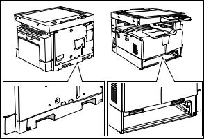
GENERAL PRECAUTIONS REGARDING THE SERVICE FOR e-STUDIO181/211
The installation and service should be done by a qualified service technician.
1)Transportation/Installation
—When transporting/installing the equipment, remove the drawer, employ two persons and be sure to hold the positions as shown in the figure.
The equipment is quite heavy and weighs approximately 34 kg (74.96 lb), therefore pay full attention when handling it.
—Be sure not to hold the movable parts or units (e.g. the control panel, ADU or RADF) when transporting the equipment
—Be sure to use a dedicated outlet with AC 110 V / 13.2 A, 115 V or 127 V / 12 A, 220-240 V or 240 V / 8 A for its power source.
—The equipment must be grounded for safety.
—Select a suitable place for installation. Avoid excessive heat, high humidity, dust, vibration and direct sunlight.
—Provide proper ventilation since the equipment emits a slight amount of ozone.
—To insure adequate working space for the copying operation, keep a minimum clearance of 80 cm (32”) on the left, 80 cm (32”) on the right and 10 cm (4”) on the rear.
—The equipment shall be installed near the socket outlet and shall be easily accessible.
—Be sure to fix and plug in the power cable securely after the installation so that no one trips over it.
—When the equipment is used after the option is removed, be sure to install the parts or the covers which have been taken off so that the inside of the equipment is not exposed.
2)General Precautions at Service
—Be sure to turn the power OFF and unplug the power cable during service (except for the service should be done with the power turned ON).
—Unplug the power cable and clean the area around the prongs of the plug and socket outlet once a year or more. A fire may occur when dust lies on this area.
—When the parts are disassembled, reassembly is the reverse of disassembly unless otherwise noted in this manual or other related documents. Be careful not to install small parts such as screws, washers, pins, E-rings, star washers in the wrong places.
—Basically, the equipment should not be operated with any parts removed or disassembled.
—The PC board must be stored in an anti-electrostatic bag and handled carefully using a wristband since the ICs on it may be damaged due to static electricity.
Caution: Before using the wristband, unplug the power cable of the equipment and make sure that there are no charged objects which are not insulated in the vicinity.
—Avoid expose to laser beam during service. This equipment uses a laser diode. Be sure not to expose your eyes to the laser beam. Do not insert reflecting parts or tools such as a screwdriver on the laser beam path. Remove all reflecting metals such as watches, rings, etc. before starting service.
—Be sure not to touch high-temperature sections such as the exposure lamp, fuser unit, damp heater and areas around them.
—Be sure not to touch high-voltage sections such as the chargers, developer, high-voltage transformer and power supply unit. Especially, the board of these components should not be touched since the electric charge may remain in the capacitors, etc. on them even after the power is turned OFF.
—Make sure that the equipment will not operate before touching potentially dangerous places (e.g. rotating/operating sections such as gears, belts pulleys, fans and laser beam exit of the laser optical unit).
—Be careful when removing the covers since there might be the parts with very sharp edges underneath.
—When servicing the equipment with the power turned ON, be sure not to touch live sections and rotating/operating sections. Avoid exposing your eyes to laser beam.
—Use designated jigs and tools.
—Use recommended measuring instruments or equivalents.
—Return the equipment to the original state and check the operation when the service is finished.
3)Important Service Parts for Safety
—The breaker, door switch, fuse, thermostat, thermofuse, thermistor, batteries, IC-RAMs including lithium batteries, etc. are particularly important for safety. Be sure to handle/install them properly. If these parts are short-circuited and their functions become ineffective, they may result in fatal accidents such as burnout. Do not allow a short-circuit and/or do not use the parts not recommended by Toshiba TEC Corporation.
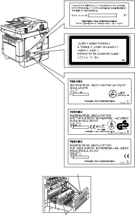
4)Cautionary Labels
—During servicing, be sure to check the rating plate and cautionary labels such as “Unplug the power cable during service”, “CAUTION. HOT”, “CAUTION. HIGH VOLTAGE”, “CAUTION. LASER BEAM”, etc. to see if there is any dirt on their surface and if they are properly stuck to the equipment.
Certification label (For UC)
Explanatory label
Identification label
For UC
For EU
For others
Warning for high-temperature areas (ventilation holes)
Warning for high-temperature areas (fuser unit)

5)Disposal of the Equipment, Supplies, Packing Materials, Used Batteries and IC-RAMs
—Regarding the recovery and disposal of the equipment, supplies, packing materials, used batteries and IC-RAMs including lithium batteries, follow the relevant local regulations or rules.
Caution:
Dispose of used batteries and IC-RAMs including lithium batteries according to this manual.
Attention:
Se débarrasser de batteries et IC-RAMs usés y compris les batteries en lithium selon ce manuel.
Vorsicht:
Entsorgung der gebrauchten Batterien und IC-RAMs (inclusive der Lithium-Batterie) nach diesem Handbuch.

ALLEGEMEINE SICHERHEITSMASSNAHMEN IN BEZUG AUF DIE WARTUNG FÜR e-STUDIO181/211
Die Installation und die Wartung sind von einem qualifizierten ServiceTechniker durchzuführen.
1)Transport/Installation
—Zum Transportieren/Installieren des Gerätes werden 2 Personen benötigt. Die Kassette zuerst herausnehmen und nur an den in der Abbildung gezeigten Stellen tragen.
Das Gerät ist sehr schwer und wiegt etwa 34 kg; deshalb muss bei der Handhabung des Geräts besonders aufgepasst werden.
—Beim Transportieren des Geräts nicht an den beweglichen Teilen oder Einheiten halten.
—Eine spezielle Steckdose mit Stromversorgung von AC 110 V / 13.2 A, 115 V oder 127 V / 12 A, 220-240 V / 8 A als Stromquelle verwenden.
—Das Gerät ist aus Sicherheitsgründen zu erden.
—Einen geeigneten Standort für die Installation wählen. Standorte mit zuviel Hitze, hoher Luftfeuchtigkeit, Staub, Vibrieren und direkter Sonneneinstrahlung sind zu vermeiden.
—Für ausreichende Belüftung sorgen, da das Gerät etwas Ozon abgibt.
—Um einen optimalen Kopierbetrieb zu gewährleisten, muss ein Abstand von mindestens 80 cm links, 80 cm rechts und 10 cm dahinter eingehalten werden.
—Das Gerät ist in der Nähe der Steckdose zu installieren; diese muss leicht zu erreichen sein.
—Nach der Installation muss das Netzkabel richtig hineingesteckt und befestigt werden, damit niemand darüber stolpern kann.
2)Allgemeine Sicherheitsmassnahmen in bezug auf die Wartung
—Während der Wartung das Gerät ausschalten und das Netzkabel herausziehen (ausser Wartung, die bei einem eingeschalteten Gerät, durchgeführt werden muss).
—Das Netzkabel herausziehen und den Bereich um die Steckerpole und die Steckdose die Umgebung in der Nähe von den Steckerzacken und der Steckdose wenigstens einmal im Jahr reinigen. Wenn Staub sich in dieser Gegend ansammelt, kann dies ein Feuer verursachen.
—Wenn die Teile auseinandergenommen werden, wenn nicht anders in diesem Handbuch usw erklärt, ist das Zusammenbauen in umgekehrter Reihenfolge durchzuführen. Aufpassen, dass kleine Teile wie Schrauben, Dichtungsringe, Bolzen, E-Ringe, Stern-Dichtungsringe, Kabelbäume nicht an den verkehrten Stellen eingebaut werden.
—Grundsätzlich darf das Gerät mit enfernten oder auseinandergenommenen Teilen nicht in Betrieb genommen werden.
—Das PC-Board muss in einer Anti-elektrostatischen Hülle gelagert werden. Nur Mit einer Manschette bei Betätigung eines Armbandes anfassen, sonst könnte es sein, dass die integrierten Schaltkreise durch statische Elektrizität beschädigt werden.
Vorsicht: Vor Benutzung der Manschette der Betätigung des Armbandes, das Netzkabel des Gerätes herausziehen und prüfen, dass es in der Nähe keine geladenen Gegenstände, die nicht isoliert sind, gibt.
—Setzen Sie sich während der Wartungsarbeiten nicht dem Laserstrahl aus. Dieses Gerät ist mit einer Laserdiode ausgestattet. Es ist unbedingt zu vermeiden, direkt in den Laserstrahl zu blicken. Keine reflektierenden Teile oder Werkzeuge, wie z. B. Schraubendreher, in den Pfad des Laserstrahls halten. Vor den Wartungsarbeiten sämtliche reflektierenden Metallgegenstände, wie Uhren, Ringe usw., entfernen.
—Auf keinen Fall Hochtemperaturbereiche, wie die Belichtungslampe, die Fixiereinheit, die Heizquelle und die umliegenden Bereiche, berühren.
—Auf keinen Fall Hochspannungsbereiche, wie die Ladeeinheiten, die Entwicklereinheit, den Hochspannungstransformator, und das Netzgerät, berühren. Insbesondere sollten die Platinen dieser Komponenten nicht berührt werden, da die Kondensatoren usw. auch nach dem Ausschalten des Geräts noch elektrisch geladen sein können.
—Vor dem Berühren potenziell gefährlicher Bereiche (z. B. drehbare oder betriebsrelevante Bereiche, wie Zahnräder, Riemen, Riemenscheiben, Lüfter und die Laseraustrittsöffnung der optischen Lasereinheit) sicherstellen, dass das Gerät sich nicht bedienen lässt.
—Beim Entfernen von Abdeckungen vorsichtig vorgehen, da sich darunter scharfkantige Komponenten befinden können.
—Bei Wartungsarbeiten am eingeschalteten Gerät dürfen keine unter Strom stehenden, drehbaren oder betriebsrelevanten Bereiche berührt werden. Nicht direkt in den Laserstrahl blicken.
—Ausschließlich vorgesehene Werkzeuge und Hilfsmittel verwenden.
—Empfohlene oder gleichwertige Messgeräte verwenden.
—Nach Abschluss der Wartungsarbeiten das Gerät in den ursprünglichen Zustand zurück versetzen und den einwandfreien Betrieb überprüfen.
3)Sicherheitsrelevante Wartungsteile
—Der Leistungsschutzschalter, der Türschalter, die Sicherung, der Thermostat, die Thermosicherung, der Thermistor, die IC-RAMs einschließlich der Lithiumakkus usw. sind besonders sicherheitsrelevant. Sie müssen unbedingt korrekt gehandhabt und installiert werden. Wenn diese Teile kurzgeschlossen und funktionsunfähig werden, kann dies zu schwerwiegenden Schäden, wie einem Abbrand, führen. Kurzschlüsse sind zu vermeiden, und es sind ausschließlich Teile zu verwenden, die von der Toshiba TEC Corporation empfohlen sind.
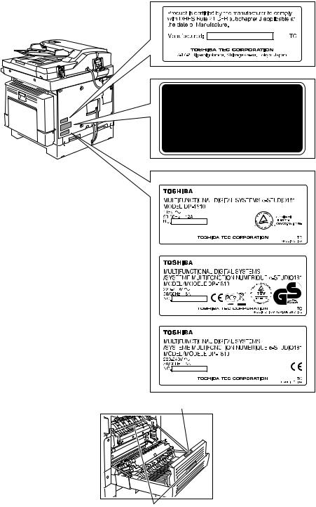
4)Warnetiketten
—Im Rahmen der Wartung unbedingt das Leistungsschild und die Etiketten mit Warnhinweisen überprüfen [z. B. „Unplug the power cable during service“ („Netzkabel vor Beginn der Wartungsarbeiten abziehen“), „CAUTION. HOT“ („VORSICHT, HEISS“), „CAUTION. HIGH VOLTAGE“ („VORSICHT, HOCHSPANNUNG“), „CAUTION. LASER BEAM“ („VORSICHT, LASER“) usw.], um sicherzustellen, dass sie nicht verschmutzt sind und korrekt am Gerät angebracht sind.
Certification label (For UC)
Explanatory label
Identification label
For UC
For EU
For others
Warning for high-temperature areas (ventilation holes)
Warning for high-temperature areas (fuser unit)

5)Entsorgung des Geräts, der Verbrauchsund Verpackungsmaterialien, alter Akkus und IC-RAMs
—In Bezug auf die Entsorgung und Wiederverwertung des Geräts, der Verbrauchsund Verpackungsmaterialien, alter Akkus und IC-RAMs, einschließlich Lithiumakkus, sind die einschlägigen nationalen oder regionalen Vorschriften zu befolgen.
Caution:
Dispose of used batteries and IC-RAMs including lithium batteries according to this manual.
Attention:
Se débarrasser de batteries et IC-RAMs usés y compris les batteries en lithium selon ce manuel.
Vorsicht:
Entsorgung der gebrauchten Batterien und IC-RAMs (inclusive der Lithium-Batterie) nach diesem Handbuch.
![]()
•Laseremissionseinheit
Diese Einheit besteht aus der Laserdiode, dem Fokussierungsobjektiv, der Blende und dem Zylinderobjektiv.
—Laserdiode
Diese Laserdiode zeichnet sich durch eine geringe Regeldifferenz, eine kleine Laservariation und einen niedrigen Schwellenstrom aus.
Die Blende der Laseremissionseinheit ist unter dem Fokussierobjektiv angeordnet, um die Form der Laserstrahlen in der primären und sekundären Scanrichtung festzulegen.
Die Laserdiode gibt Laserstrahlen als Reaktion auf die Signale der Laseremissionssteuerung (ein/ aus) von der Lasertreiber-PC-Platine (LDR) aus. Die durch das Fokussierobjektiv geführten Laserstrahlen werden auf die Trommeloberfläche fokussiert.
—Vorsichtsmaßnahmen im Zusammenhang mit Lasern
Dieses Gerät enthält eine Laserdiode, die einen unsichtbaren Laserstrahl emittiert.
Da man diesen Laserstrahl nicht sehen kann, ist bei der Handhabung der Komponenten der optischen Lasereinheit, bei der Durchführung von Arbeiten und bei der Justierung des Laserstrahls äußerste Vorsicht geboten. Arbeiten dürfen niemals anhand anderer als den vorgeschriebenen Anleitungen durchgeführt werden; andernfalls kann es zu einer Schädigung Exposition durch Laserstrahlung kommen.
Die Lasereinheit ist vollständig mit einer Schutzabdeckung versiegelt. Solange ausschließlich die Arbeitsschritte der vorgeschriebenen Anleitungen durchgeführt werden, tritt der Laserstrahl nicht aus, und es besteht keine Gefahr, der Laserstrahlung ausgesetzt zu werden.
Das folgende Laser-Warnetikett ist an der Abdeckung vorne rechts angebracht.
•Warnhinweise:
—Setzen Sie sich während der Wartungsarbeiten nicht dem Laserstrahl aus.
Dieses Gerät ist mit einer Laserdiode ausgestattet. Es ist unbedingt zu vermeiden, direkt in den Laserstrahl zu blicken. Keine reflektierenden Teile oder Werkzeuge, wie z. B. Schraubendreher, in den Pfad des Laserstrahls halten. Vor den Wartungsarbeiten sämtliche reflektierenden Metallgegenstände, wie Uhren, Ringe usw., entfernen.
—Bei Wartungsarbeiten am eingeschalteten Gerät dürfen keine unter Strom stehenden, drehbaren oder betriebsrelevanten Bereiche berührt werden. Nicht direkt in den Laserstrahl blicken.
—Im Rahmen der Wartung unbedingt das Leistungsschild und die Etiketten mit Warnhinweisen überprüfen [z. B. „Unplug the power cable during service“ („Netzkabel vor Beginn der Wartungsarbeiten abziehen“), „CAUTION. HOT“ („VORSICHT, HEISS“), „CAUTION. HIGH VOLTAGE“ („VORSICHT, HOCHSPANNUNG“), „CAUTION. LASER BEAM“ („VORSICHT, LASER“) usw.], um sicherzustellen, dass sie nicht verschmutzt sind und korrekt am Gerät angebracht sind.
CONTENTS
|
1. SPECIFICATIONS / ACCESSORIES / OPTIONS / SUPPLIES …………………………….. |
1-1 |
|
|
1.1 |
Specifications……………………………………………………………………………………………………….. |
1-1 |
|
1.2 |
Accessories …………………………………………………………………………………………………………. |
1-4 |
|
1.3 |
Options ……………………………………………………………………………………………………………….. |
1-5 |
|
1.4 |
Supplies………………………………………………………………………………………………………………. |
1-6 |
|
1.5 |
System List ………………………………………………………………………………………………………….. |
1-7 |
|
2. OUTLINE OF THE MACHINE …………………………………………………………………………… |
2-1 |
||
|
2.1 |
Sectional View ……………………………………………………………………………………………………… |
2-1 |
|
|
2.2 |
Electric Parts Layout……………………………………………………………………………………………… |
2-4 |
|
|
2.2.1 |
Scanner, control panel ………………………………………………………………………………… |
2-4 |
|
|
2.2.2 Power supply section, switches…………………………………………………………………….. |
2-5 |
||
|
2.2.3 Laser optical unit, fuser unit, toner cartridge section………………………………………… |
2-6 |
||
|
2.2.4 |
Developer unit section…………………………………………………………………………………. |
2-7 |
|
|
2.2.5 |
Driving section……………………………………………………………………………………………. |
2-8 |
|
|
2.2.6 |
Drawer section …………………………………………………………………………………………… |
2-9 |
|
|
2.2.7 |
Bypass unit………………………………………………………………………………………………. |
2-10 |
|
|
2.3 Symbols and Functions of Various Components……………………………………………………… |
2-11 |
||
|
2.4 |
General Description…………………………………………………………………………………………….. |
2-15 |
|
|
2.4.1 |
System block diagram ……………………………………………………………………………….. |
2-15 |
|
|
2.4.2 |
Construction of boards ………………………………………………………………………………. |
2-16 |
|
|
2.5 Disassembly and Replacement of Covers………………………………………………………………. |
2-18 |
||
|
2.5.1 |
Front cover ………………………………………………………………………………………………. |
2-18 |
|
|
2.5.2 |
Inner tray …………………………………………………………………………………………………. |
2-18 |
|
|
2.5.3 |
Left cover…………………………………………………………………………………………………. |
2-18 |
|
|
2.5.4 |
Tray rear cover …………………………………………………………………………………………. |
2-19 |
|
|
2.5.5 |
Front right cover ……………………………………………………………………………………….. |
2-19 |
|
|
2.5.6 |
Front upper cover ……………………………………………………………………………………… |
2-19 |
|
|
2.5.7 |
ADU cover ……………………………………………………………………………………………….. |
2-20 |
|
|
2.5.8 |
Right front cover ……………………………………………………………………………………….. |
2-20 |
|
|
2.5.9 |
Right rear cover………………………………………………………………………………………… |
2-21 |
|
|
2.5.10 Rear cover……………………………………………………………………………………………….. |
2-21 |
||
|
2.6 Disassembly and Replacement of PC boards …………………………………………………………. |
2-22 |
||
|
2.6.1 |
MAIN board (MAIN)…………………………………………………………………………………… |
2-22 |
|
|
2.6.2 |
SRAM board (SRAM) ………………………………………………………………………………… |
2-23 |
|
|
2.6.3 Fuse PC board (FUS)………………………………………………………………………………… |
2-24 |
||
|
2.6.4 Switching regulator unit (PS)………………………………………………………………………. |
2-24 |
||
|
2.6.5 Switching regulator cooling fan (M6) ……………………………………………………………. |
2-27 |
||
|
2.7 Removal and Installation of Options………………………………………………………………………. |
2-28 |
||
|
2.7.1 MR-2020 (Automatic Document Feeder (ADF))/ |
|||
|
MR-3023 (Reversing Automatic Document Feeder (RADF)) …………………………… |
2-28 |
||
|
2.7.2 MY-1027 (Paper Feed Unit (PFU))………………………………………………………………. |
2-30 |
|
3. COPY PROCESS ……………………………………………………………………………………………. |
3-1 |
|
|
3.1 |
General Description of Copying Process………………………………………………………………….. |
3-1 |
|
3.2 |
Details of Copying Process…………………………………………………………………………………….. |
3-2 |
|
3.3 |
Comparison with e-STUDIO165/205 ……………………………………………………………………… |
3-13 |
|
4. GENERAL OPERATION………………………………………………………………………………….. |
4-1 |
|
|
4.1 |
Overview of Operation …………………………………………………………………………………………… |
4-1 |
|
4.2 |
Description of Operation………………………………………………………………………………………… |
4-2 |
|
4.2.1 Warming-up……………………………………………………………………………………………….. |
4-2 |
|
|
4.2.2 Ready state (ready for copying) ……………………………………………………………………. |
4-2 |
|
|
© 2009 TOSHIBA TEC CORPORATION All rights reserved |
e-STUDIO181/211 |
|
|
CONTENTS |
1
|
4.2.3 |
Drawer feed copying …………………………………………………………………………………… |
4-3 |
||
|
4.2.4 |
Bypass feed copying …………………………………………………………………………………… |
4-4 |
||
|
4.2.5 |
Interruption copying…………………………………………………………………………………….. |
4-4 |
||
|
4.3 |
Detection of Abnormality………………………………………………………………………………………… |
4-5 |
||
|
4.3.1 |
Types of abnormality …………………………………………………………………………………… |
4-5 |
||
|
4.3.2 |
Description of abnormality……………………………………………………………………………. |
4-6 |
||
|
5. |
CONTROL PANEL………………………………………………………………………………………….. |
5-1 |
||
|
5.1 |
Control Panel and LED Display ……………………………………………………………………………… |
5-1 |
||
|
5.2 |
Items Displayed on Control Panel …………………………………………………………………………… |
5-2 |
||
|
5.3 |
Relation between Equipment State and Operation…………………………………………………….. |
5-4 |
||
|
5.4 |
Operation…………………………………………………………………………………………………………….. |
5-5 |
||
|
5.4.1 |
Block diagram…………………………………………………………………………………………….. |
5-5 |
||
|
5.4.2 |
LED display circuit………………………………………………………………………………………. |
5-5 |
||
|
5.5 |
Disassembly and Replacement ………………………………………………………………………………. |
5-6 |
||
|
5.5.1 |
Control panel unit ……………………………………………………………………………………….. |
5-6 |
||
|
5.5.2 Control panel PC board (LPNL) ……………………………………………………………………. |
5-6 |
|||
|
6. |
SCANNER ……………………………………………………………………………………………………… |
6-1 |
||
|
6.1 |
General Description………………………………………………………………………………………………. |
6-1 |
||
|
6.2 |
Construction…………………………………………………………………………………………………………. |
6-2 |
||
|
6.3 |
Functions …………………………………………………………………………………………………………….. |
6-3 |
||
|
6.4 |
Description of Operation………………………………………………………………………………………… |
6-5 |
||
|
6.4.1 |
Scanning operation …………………………………………………………………………………….. |
6-5 |
||
|
6.4.2 Scan motor drive circuit……………………………………………………………………………….. |
6-6 |
|||
|
6.5 |
Contact Image Sensor Unit Control Circuit……………………………………………………………….. |
6-8 |
||
|
6.5.1 Exposure LED control circuit ………………………………………………………………………… |
6-8 |
|||
|
6.5.2 |
CCD control circuit ……………………………………………………………………………………… |
6-9 |
||
|
6.6 |
Disassembly and Replacement …………………………………………………………………………….. |
6-10 |
||
|
6.6.1 |
Original glass……………………………………………………………………………………………. |
6-10 |
||
|
6.6.2 |
Scanner top cover …………………………………………………………………………………….. |
6-11 |
||
|
6.6.3 |
Scan motor (M1)……………………………………………………………………………………….. |
6-11 |
||
|
6.6.4 CIS home position sensor (S1) …………………………………………………………………… |
6-13 |
|||
|
6.6.5 |
Platen sensor (S2)…………………………………………………………………………………….. |
6-13 |
||
|
6.6.6 |
CIS unit (CIS) …………………………………………………………………………………………… |
6-14 |
||
|
6.6.7 |
CIS case………………………………………………………………………………………………….. |
6-16 |
||
|
6.6.8 CIS unit drive belt-1 ………………………………………………………………………………….. |
6-17 |
|||
|
6.6.9 CIS unit drive belt-2…………………………………………………………………………………… |
6-18 |
|||
|
7. |
LASER OPTICAL UNIT …………………………………………………………………………………… |
7-1 |
||
|
7.1 |
General Description………………………………………………………………………………………………. |
7-1 |
||
|
7.2 |
Structure ……………………………………………………………………………………………………………… |
7-2 |
||
|
7.3 |
Laser Diode Control Circuit…………………………………………………………………………………….. |
7-5 |
||
|
7.4 |
Polygonal Motor Control Circuit ………………………………………………………………………………. |
7-6 |
||
|
7.5 |
Disassembly and Replacement ………………………………………………………………………………. |
7-7 |
||
|
7.5.1 |
Laser optical unit ………………………………………………………………………………………… |
7-7 |
||
|
8. |
DRIVE UNIT …………………………………………………………………………………………………… |
8-1 |
||
|
8.1 |
General Description………………………………………………………………………………………………. |
8-1 |
||
|
8.2 |
Configuration ……………………………………………………………………………………………………….. |
8-2 |
||
|
8.3 |
Functions ……………………………………………………………………………………………………………. |
8-3 |
||
|
8.4 |
Main Motor Control Circuit……………………………………………………………………………………… |
8-4 |
||
|
8.5 |
Disassembly and Replacement ………………………………………………………………………………. |
8-6 |
||
|
8.5.1 |
Main motor (M3) …………………………………………………………………………………………. |
8-6 |
||
|
8.5.2 |
Toner motor (M2) ……………………………………………………………………………………….. |
8-6 |
||
|
8.5.3 Main motor drive unit…………………………………………………………………………………… |
8-7 |
|||
|
e-STUDIO181/211 |
© 2009 TOSHIBA TEC CORPORATION All rights reserved |
|||
|
CONTENTS |
2
|
9. PAPER FEEDING SYSTEM……………………………………………………………………………… |
9-1 |
||
|
9.1 |
General Description………………………………………………………………………………………………. |
9-1 |
|
|
9.2 |
Configuration ……………………………………………………………………………………………………….. |
9-2 |
|
|
9.3 |
Functions …………………………………………………………………………………………………………….. |
9-3 |
|
|
9.4 |
Operation…………………………………………………………………………………………………………….. |
9-5 |
|
|
9.4.1 |
Drawer………………………………………………………………………………………………………. |
9-5 |
|
|
9.4.2 |
Bypass tray………………………………………………………………………………………………… |
9-7 |
|
|
9.4.3 |
General operation……………………………………………………………………………………….. |
9-9 |
|
|
9.5 |
Disassembly and Replacement …………………………………………………………………………….. |
9-10 |
|
|
9.5.1 |
Bypass unit………………………………………………………………………………………………. |
9-10 |
|
|
9.5.2 |
Bypass tray………………………………………………………………………………………………. |
9-11 |
|
|
9.5.3 |
Bypass separation pad ……………………………………………………………………………… |
9-11 |
|
|
9.5.4 |
Bypass roller unit………………………………………………………………………………………. |
9-12 |
|
|
9.5.5 |
Bypass pickup roller …………………………………………………………………………………. |
9-14 |
|
|
9.5.6 |
Bypass feed roller …………………………………………………………………………………….. |
9-14 |
|
|
9.5.7 |
Bypass paper sensor (S8)………………………………………………………………………….. |
9-14 |
|
|
9.5.8 |
Bypass pickup solenoid (SOL2) ………………………………………………………………….. |
9-15 |
|
|
9.5.9 |
Bypass pickup clutch / Bypass feed clutch……………………………………………………. |
9-16 |
|
|
9.5.10 |
Damp heater unit (DH3) / Dummy plate ……………………………………………………….. |
9-18 |
|
|
9.5.11 |
Paper empty sensor (S7) …………………………………………………………………………… |
9-18 |
|
|
9.5.12 |
Pickup roller …………………………………………………………………………………………….. |
9-19 |
|
|
9.5.13 |
Registration clutch (CLT1)………………………………………………………………………….. |
9-20 |
|
|
9.5.14 |
Pickup solenoid (SOL1)……………………………………………………………………………… |
9-20 |
|
|
9.5.15 |
Drawer pickup clutch …………………………………………………………………………………. |
9-21 |
|
|
9.5.16 |
Registration roller (rubber) …………………………………………………………………………. |
9-22 |
|
|
9.5.17 |
Registration roller (metal) …………………………………………………………………………… |
9-23 |
|
|
9.5.18 |
Feed gear unit ………………………………………………………………………………………….. |
9-24 |
|
|
9.5.19 |
Drawer detection switch (SW5) …………………………………………………………………… |
9-24 |
|
|
9.5.20 |
Registration sensor (S4)…………………………………………………………………………….. |
9-25 |
|
10. DRUM RELATED SECTION …………………………………………………………………………… |
10-1 |
|
|
10.1 |
General Description…………………………………………………………………………………………….. |
10-1 |
|
10.2 |
Configuration ……………………………………………………………………………………………………… |
10-2 |
|
10.3 |
Functions …………………………………………………………………………………………………………… |
10-3 |
|
10.4 |
High-Voltage Output Control Circuit ………………………………………………………………………. |
10-5 |
|
10.4.1 General description …………………………………………………………………………………… |
10-5 |
|
|
10.4.2 Description of Operation…………………………………………………………………………….. |
10-6 |
|
|
10.5 |
Drum Temperature Detection Circuit ……………………………………………………………………… |
10-7 |
|
10.5.1 General description …………………………………………………………………………………… |
10-7 |
|
|
10.5.2 Circuit configuration…………………………………………………………………………………… |
10-7 |
|
|
10.6 |
Temperature/Humidity Detection Circuit…………………………………………………………………. |
10-8 |
|
10.6.1 General Description…………………………………………………………………………………… |
10-8 |
|
|
10.6.2 Circuit configuration…………………………………………………………………………………… |
10-8 |
|
|
10.7 |
Disassembly and Replacement …………………………………………………………………………….. |
10-9 |
|
10.7.1 Process unit……………………………………………………………………………………………… |
10-9 |
|
|
10.7.2 Drum cleaner unit ……………………………………………………………………………………. |
10-10 |
|
|
10.7.3 Discharge LED (ERS) ……………………………………………………………………………… |
10-11 |
|
|
10.7.4 Main charger ………………………………………………………………………………………….. |
10-12 |
|
|
10.7.5 Main charger grid …………………………………………………………………………………… |
10-12 |
|
|
10.7.6 Main charger cleaner……………………………………………………………………………….. |
10-13 |
|
|
10.7.7 Needle electrode ……………………………………………………………………………………. |
10-13 |
|
|
10.7.8 Drum …………………………………………………………………………………………………….. |
10-14 |
|
|
10.7.9 Drum cleaning blade ………………………………………………………………………………. |
10-14 |
|
|
10.7.10Drum separation finger …………………………………………………………………………… |
10-14 |
|
|
10.7.11Recovery blade ……………………………………………………………………………………… |
10-15 |
|
|
© 2009 TOSHIBA TEC CORPORATION All rights reserved |
e-STUDIO181/211 |
|
|
CONTENTS |
3
|
10.7.12Transfer/Separation charger…………………………………………………………………….. |
10-15 |
||
|
10.7.13Charger wire …………………………………………………………………………………………. |
10-16 |
||
|
10.7.14Transfer unit…………………………………………………………………………………………… |
10-17 |
||
|
10.7.15Ozone filter …………………………………………………………………………………………… |
10-18 |
||
|
10.7.16Exhaust fan (M5) ……………………………………………………………………………………. |
10-19 |
||
|
10.7.17Temperature/humidity sensor (S3) ……………………………………………………………. |
10-20 |
||
|
10.7.18Toner cartridge interface PC board (CTIF) …………………………………………………. |
10-21 |
||
|
11. DEVELOPMENT SYSTEM……………………………………………………………………………… |
11-1 |
||
|
11.1 |
General Description…………………………………………………………………………………………….. |
11-1 |
|
|
11.2 |
Construction……………………………………………………………………………………………………….. |
11-2 |
|
|
11.3 |
Functions …………………………………………………………………………………………………………… |
11-3 |
|
|
11.3.1 Function of each unit …………………………………………………………………………………. |
11-3 |
||
|
11.3.2 Functions of the toner cartridge PC board (CTRG) ………………………………………… |
11-4 |
||
|
11.3.3 Recovered toner supply mechanism ……………………………………………………………. |
11-6 |
||
|
11.4 |
Toner Motor Control Circuit ………………………………………………………………………………….. |
11-7 |
|
|
11.5 |
Auto-Toner Circuit……………………………………………………………………………………………….. |
11-8 |
|
|
11.5.1 General description …………………………………………………………………………………… |
11-8 |
||
|
11.5.2 Function of auto-toner sensor …………………………………………………………………….. |
11-9 |
||
|
11.6 |
Disassembly and Replacement …………………………………………………………………………… |
11-11 |
|
|
11.6.1 Developer unit ………………………………………………………………………………………… |
11-11 |
||
|
11.6.2 Developer material …………………………………………………………………………………. |
11-12 |
||
|
11.6.3 Filling developer unit with developer material………………………………………………. |
11-13 |
||
|
11.6.4 Auto-toner sensor (S6) …………………………………………………………………………….. |
11-14 |
||
|
11.6.5 Drum thermistor (THMS4) ………………………………………………………………………… |
11-14 |
||
|
11.6.6 Guide roller / Developer sleeve …………………………………………………………………. |
11-14 |
||
|
11.6.7 Mixer……………………………………………………………………………………………………… |
11-18 |
||
|
11.6.8 Replacement of Oil Seal…………………………………………………………………………… |
11-20 |
||
|
12. FUSER / EXIT UNIT ………………………………………………………………………………………. |
12-1 |
||
|
12.1 |
General Description…………………………………………………………………………………………….. |
12-1 |
|
|
12.2 |
Configurations…………………………………………………………………………………………………….. |
12-2 |
|
|
12.3 |
Functions …………………………………………………………………………………………………………… |
12-3 |
|
|
12.4 |
Operation…………………………………………………………………………………………………………… |
12-4 |
|
|
12.5 |
Fuser Unit Control Circuit …………………………………………………………………………………….. |
12-5 |
|
|
12.5.1 Configuration ……………………………………………………………………………………………. |
12-5 |
||
|
12.5.2 Temperature detection section……………………………………………………………………. |
12-6 |
||
|
12.6 |
Disassembly and Replacement …………………………………………………………………………… |
12-11 |
|
|
12.6.1 Fuser/Paper exit unit ……………………………………………………………………………….. |
12-13 |
||
|
12.6.2 Pressure roller unit / Fuser roller unit ………………………………………………………… |
12-13 |
||
|
12.6.3 Exit roller ……………………………………………………………………………………………….. |
12-14 |
||
|
12.6.4 Exit sensor (S5) ……………………………………………………………………………………… |
12-15 |
||
|
12.6.5 Separation finger …………………………………………………………………………………… |
12-17 |
||
|
12.6.6 Center heater lamp / Side heater lamp (LAMP1/LAMP2)………………………………. |
12-17 |
||
|
12.6.7 Fuser roller ……………………………………………………………………………………………. |
12-18 |
||
|
12.6.8 Pressure roller ……………………………………………………………………………………….. |
12-19 |
||
|
12.6.9 Center thermistor / Side thermistor / Edge thermistor (THMS1/THMS2/THMS3) 12-20 |
|||
|
12.6.10Fuser thermostat (THMO1)………………………………………………………………………. |
12-21 |
||
|
13. POWER SUPPLY UNIT …………………………………………………………………………………. |
13-1 |
||
|
13.1 |
Construction……………………………………………………………………………………………………….. |
13-1 |
|
|
13.2 |
Operation of DC Output Circuit……………………………………………………………………………… |
13-2 |
|
|
13.3 |
Output Channel ………………………………………………………………………………………………….. |
13-3 |
|
|
13.4 |
Fuse………………………………………………………………………………………………………………….. |
13-4 |
|
|
13.5 |
Configuration of Power Supply Unit……………………………………………………………………….. |
13-5 |
|
|
13.6 |
AC Wire Harness………………………………………………………………………………………………… |
13-6 |
|
|
e-STUDIO181/211 |
© 2009 TOSHIBA TEC CORPORATION All rights reserved |
||
|
CONTENTS |
4
|
14. EXTERNAL COUNTERS ……………………………………………………………………………….. |
14-1 |
|
|
14.1 |
Outline ………………………………………………………………………………………………………………. |
14-1 |
|
14.2 |
Signal………………………………………………………………………………………………………………… |
14-1 |
|
14.2.1 Pin Layout ……………………………………………………………………………………………….. |
14-1 |
|
|
14.2.2 Details of the signals …………………………………………………………………………………. |
14-2 |
|
|
14.3 |
Notices………………………………………………………………………………………………………………. |
14-3 |
|
14.3.1 Setting code …………………………………………………………………………………………….. |
14-3 |
|
|
14.3.2 Setting value change and restrictions when using the totalizer (DocuLyzerNW) … |
14-3 |
|
|
14.3.3 Setting value change and restrictions when using the coin controller……………….. |
14-3 |
|
|
14.3.4 Simultaneous Installation of External Counters……………………………………………… |
14-3 |
|
|
15. PC BOARDS ………………………………………………………………………………………………… |
15-1 |
|
© 2009 TOSHIBA TEC CORPORATION All rights reserved |
e-STUDIO181/211 |
|
CONTENTS |
5
|
e-STUDIO181/211 |
© 2009 TOSHIBA TEC CORPORATION All rights reserved |
|
CONTENTS |
6

1.SPECIFICATIONS / ACCESSORIES / OPTIONS / SUPPLIES
Values in [ ] are for e- STUDIO211 in case that the specification is different among e-STUDIO181 and e-STUDIO211.
|
Copy process |
Indirect electrophotographic process (dry) |
|||||
|
Type |
Desktop type |
|||||
|
Original table |
Fixed type (the left rear corner used as guide to place originals) |
|||||
|
Accepted originals |
Sheet, book and 3-dimensional object. The automatic document feeder |
|||||
|
(ADF) only accepts paper which are not pasted or stapled. (Single-sided |
||||||
|
originals: 50 to 127 g/m2/13 to 34 lb. Bond) Carbon paper are not acceptable |
||||||
|
either. |
||||||
|
Maximum size: A3/LD |
||||||
|
Copy speed (Copies/min.) |
||||||
|
e-STUDIO181 |
||||||
|
Paper size |
Drawer |
Bypass feed |
PFU |
|||
|
Size specified |
Size not specified |
|||||
|
A4, B5, LT |
18 |
16 |
11 |
16 |
||
|
A5-R, ST-R |
— |
16 |
11 |
— |
||
|
A4-R, B5-R, LT-R |
15.5 |
15.5 |
11 |
15.5 |
||
|
B4, LG, FOLIO, COMPUTER |
13 |
13 |
11 |
13 |
||
|
A3, LD |
11 |
11 |
11 |
11 |
||
|
e-STUDIO211 |
||||||
|
Paper size |
Drawer |
Bypass feed |
PFU |
|||
|
Size specified |
Size not specified |
|||||
|
A4, B5, LT |
21 |
20 |
11 |
20 |
||
|
A5-R, ST-R |
— |
20 |
11 |
— |
||
|
A4-R, B5-R, LT-R |
15.5 |
15.5 |
11 |
15.5 |
||
|
B4, LG, FOLIO, COMPUTER |
13 |
13 |
11 |
13 |
||
|
A3, LD |
11 |
11 |
11 |
11 |
*“–” means “Not acceptable”.
*The copy speed in the above table are available when originals are manually placed for single side, multiple copying.
*When the ADF is used, the copy speed of 16[20] sheets per minute is only available under the
|
following conditions: |
||
|
• |
Original/Mode: |
Single side original/A4/LT size. APS/automatic density are not selected. |
|
• |
Number of sheets: |
16[20] or more. |
•Reproduction ratio: 100%
|
© 2009 TOSHIBA TEC CORPORATION All rights reserved |
e-STUDIO181/211 |
SPECIFICATIONS / ACCESSORIES / OPTIONS / SUPPLIES |
1 — 1
Copy speed for thick paper (Copies/min.) e-STUDIO181/211
Thick 1 (81 g/m2 to 105 g/m2, 21.3 lb. Bond to 28 lb. Bond): Bypass feed on a sheet by sheet basis only Thick 2 (106 g/m2 to 163 g/m2, 28 lb. Bond to 90 lb. Index): Bypass feed on a sheet by sheet basis only
Copy paper
|
Drawer |
PFU |
Bypass copy |
Remarks |
|||
|
Size |
A3, A4, A4-R, |
B4, B5, |
A3 to A5-R, LD to ST-R, FOLIO, |
|||
|
B5-R, LD, LG, LT, LT-R, |
COMPUTER, 13″LG, 8.5″ x 8.5″, 8K, |
|||||
|
FOLIO, COMPUTER, |
16K, 16K-R |
|||||
|
13″LG, 8.5″ x 8.5″, 8K, |
(Non-standard or user-specified sizes |
|||||
|
16K, 16K-R |
can be set.) |
|||||
|
Weight |
64 to 80 g/m2 |
50 to 163 g/m2(Single paper feeding) |
||||
|
64 to 80 g/m2(Continuous feeding) |
||||||
|
Special |
– |
Tracing paper, labels, OHP film |
These special papers |
|||
|
paper |
(thickness: 80 µm or thicker), |
recommended by Toshiba |
||||
|
Tec |
||||||
|
First copy time ………………… |
Approx. 7.6 sec. (A4, 100%, original placed manually) |
|||||
|
Approx. 7.7 sec. (LT, 100%, original placed manually) |
||||||
|
Warming-up time……………… |
Approx. 25 sec. (temperature: 20°C) |
|||||
|
Multiple copying ………………. |
Up to 999 copies; Key in set numbers |
|||||
|
Reproduction ratio …………… |
Actual ratio: 100±0.5% |
|||||
|
Zooming: 25 to 200% in increments of 1% |
||||||
|
Resolution/Gradation |
……….. |
Scanning: 600 dpi x 600 dpi |
||||
|
Printing: Equivalent to 2400 dpi x 600 dpi |
||||||
|
Gradation: 256 steps |
||||||
|
Eliminated portion ……………. |
Leading edges: 3.0±2.0 mm, Side/trailing edges: 2.0±2.0 mm (copy) |
|||||
|
Leading / trailing edges: 5.0±2.0 mm, Side edges: 5.0±2.0 mm (print) |
||||||
|
Paper feeding ……………………. |
Standard drawer: |
|||||
|
1 drawer (stack height 28 mm, equivalent to 250 sheets; 64 to |
||||||
|
80 g/m2 (17 to 22 lb. Bond)) |
||||||
|
Bypass feeding: |
||||||
|
Stack height 11.8 mm: equivalent to 100 sheets; 64 to 80 g/m2 |
||||||
|
(17 to 22 lb. Bond) |
||||||
|
Paper Feed Unit (PFU): |
||||||
|
Option (One drawer: stack height 28 mm, equivalent to 250 |
||||||
|
sheets; 64 to 80 g/m2 (17 to 22 lb. Bond)) |
||||||
|
Capacity of originals in the automatic document feeder (Option) |
||||||
|
………………………………………….. |
A3 to A5-R, LD to ST-R: |
|||||
|
100 sheets / 80 g/m2 (Stack height 16 mm or less) |
||||||
|
Toner supply ……………………… |
Automatic toner density detection/supply |
|||||
|
Toner cartridge replacing method (There is a recovered toner supply |
||||||
|
mechanism.) |
||||||
|
Density control…………………… |
Automatic density mode and manual density mode selectable in 7 |
|||||
|
steps |
||||||
|
e-STUDIO181/211 |
© 2009 TOSHIBA TEC CORPORATION All rights reserved |
SPECIFICATIONS / ACCESSORIES / OPTIONS / SUPPLIES
1 — 2
![]()
|
Weight……………………………. |
Approx. 31.8 kg ( 70.11 lb.) (for NAD and others) |
|
|
Approx. 32.9 kg ( 72.53 lb.) (for MJD and CND) |
||
|
Approx. 34.2 kg ( 75.40 lb.) (for AUD) |
||
|
Power requirements…………. |
AC 110 V / 13.2 A, 115 V or 127 V / 12 A |
1 |
|
220-240 V or 240 V / 8 A (50/60 Hz) |
*The acceptable value of each voltage is ±10%.
|
Power consumption …………. |
1.5 kW or less (100 V series) |
1.6kW or less (200 V series)
*The electric power is supplied to the ADF and PFU through the equipment.
Total counter …………………… Electronical counter
Dimensions of the equipment
………………………………………….. W 600 x D 643 x H 462.5 (mm): See the figure below
D
H
W
Fig. 1-1
|
© 2009 TOSHIBA TEC CORPORATION All rights reserved |
e-STUDIO181/211 |
|
SPECIFICATIONS / ACCESSORIES / OPTIONS / SUPPLIES |
1 — 3
|
1.2 |
Accessories |
|
|
Unpacking/setup instruction |
1 set |
|
|
Operator’s manual |
1 pc. |
|
|
Operator’s manual pocket |
1 pc. (for NAD) |
|
|
Power cable |
1 pc. |
|
|
CD-ROM |
2 pcs. |
|
|
Rubber cap |
6 pcs. (for MJD, ASD, ASU and SAD) |
|
|
2 pcs. (for NAD, CND, AUD, TWD, KRD and ARD) |
||
|
Transfer charger wire cleaner |
1 pc. |
|
|
(installed inside of the transfer cover) |
||
|
Drum (installed inside of the equipment) |
1 pc. |
|
|
Developer material |
1 pc. |
|
|
Nozzle |
1 pc. (for NAD) |
|
|
Toner cartridge |
1 pc. |
|
|
Warranty sheet |
1 pc. (for NAD and CND) |
|
|
Setup report |
1 set (for NAD, MJD and CND) |
|
|
Customer satisfaction card |
1 pc. (for MJD) |
|
|
Packing list |
1 pc. (for CND) |
|
|
Customer survey sheet |
1 pc. (for CND) |
|
|
Certificate of conformance |
1 pc. (for CND) |
|
*Machine version
|
NAD: |
North America |
|
ASD: |
Hong Kong / Latin America |
|
AUD: |
Australia |
|
MJD: |
Europe |
|
ASU: |
Asia / Saudi Arabia |
|
SAD: |
Saudi Arabia |
|
ARD: |
Latin America |
|
CND: |
China |
|
TWD: |
Taiwan |
|
KRD: |
Korea |
|
JPD: |
Japan |
|
e-STUDIO181/211 |
© 2009 TOSHIBA TEC CORPORATION All rights reserved |
|
SPECIFICATIONS / ACCESSORIES / OPTIONS / SUPPLIES |
1 — 4

1.3Options
|
Platen Cover |
KA-1650PC/PCC |
1 |
|
Automatic Document Feeder (ADF) |
MR-2020 |
|
|
Paper Feed Unit (PFU) |
MY-1027 |
|
|
Expansion Memory |
GC-1240 |
|
|
Damp Heater |
MF-1640U/E |
|
|
Harness Kit |
GQ-1130 |
|
|
Desk |
MH-1640 |
|
|
Operator’s Manual Pocket |
KK-1660/1660C |
|
© 2009 TOSHIBA TEC CORPORATION All rights reserved |
e-STUDIO181/211 |
|
SPECIFICATIONS / ACCESSORIES / OPTIONS / SUPPLIES |
1 — 5
1.4Supplies
|
Drum |
OD-1600 (except for China) |
|
OD-2320 (for China) |
|
|
Developer material |
D-2320 (except for China) |
|
D-2320C (for China) |
|
|
Toner cartridge |
PS-ZT1810(1)(for North America) |
|
PS-ZT1810A(1)(for Latin America) |
|
|
PS-ZT1810D(1)(for Asia) |
|
|
PS-ZT1810D5k(1)(for Asia) |
|
|
PS-ZT1810C(1)(for China) |
|
|
PS-ZT1810C10k(1)(for China) |
|
|
PS-ZT1810C5k(1)(for China) |
|
|
PS-ZT1810T(1)(for Taiwan) |
|
|
PS-ZT1810T5k(1)(for Taiwan) |
|
|
PS-ZT1810E(1)(for Europe) |
|
|
PS-ZT1810E5K(1)(for Europe) |
|
e-STUDIO181/211 |
© 2009 TOSHIBA TEC CORPORATION All rights reserved |
|
SPECIFICATIONS / ACCESSORIES / OPTIONS / SUPPLIES |
1 — 6
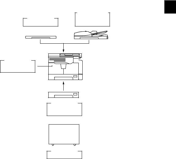
1.5System List
1
Automatic
Document Feeder
(ADF)
MR-2020
Expansion
Memory
GC-1240
Paper Feed
Unit (PFU)
MY-1027
Desk
MH-1640
Fig. 1-2
|
© 2009 TOSHIBA TEC CORPORATION All rights reserved |
e-STUDIO181/211 |
|
SPECIFICATIONS / ACCESSORIES / OPTIONS / SUPPLIES |
1 — 7
|
e-STUDIO181/211 |
© 2009 TOSHIBA TEC CORPORATION All rights reserved |
|
SPECIFICATIONS / ACCESSORIES / OPTIONS / SUPPLIES |
1 — 8
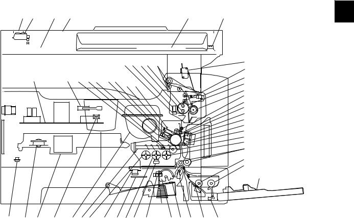
2.OUTLINE OF THE MACHINE
2.1Sectional View
1. Front side
|
A2 |
A3 |
A4 |
A1 |
A5 |
A6 |
||||||||||||||
|
J6 J7 J5 J4 |
J8 |
K5 |
|||||
|
J3 |
|||||||
|
K4 |
K2 |
I5 |
I9 F3 |
F2F1 |
H2 H3 |
J9 |
|
|
J1 |
|||||||
|
J2 |
|||||||
|
I7 |
|||||||
|
H4 |
|||||||
|
H5 |
|||||||
|
H1 |
|||||||
|
G2 |
|||||||
|
G1 |
|||||||
|
G3 |
|||||||
|
I1 |
|||||||
|
I2 |
|||||||
|
C5 |
|||||||
|
E2 |
|||||||
|
E1 |
E5
|
K3 |
B2 |
B1 |
K1 |
I8 |
I4 |
I11 I10 I3 |
I6 |
C3 |
C1 C2 C4 |
E4 |
||||
|
F4 |
E3 |
|||||||||||||
|
Fig. 2-1 |
|
A1 |
Original glass |
||
|
A2 |
ADF original glass |
||
|
A3 |
Contact image sensor unit (CIS) |
||
|
A4 |
Scanner damp heater (Left side) |
DH1 |
|
|
A5 |
Scanner damp heater (Right side) |
DH2 |
|
|
A6 |
Scanner damp heater thermostat |
THMO2 |
|
|
B1 |
Laser optical unit |
||
|
B2 |
Polygonal motor |
M4 |
|
|
C1 |
Pickup roller |
||
|
C2 |
Separation claw |
||
|
C3 |
Paper empty sensor |
S7 |
|
|
C4 |
Registration sensor |
S4 |
|
|
C5 |
Registration roller |
||
|
E1 |
Bypass pickup roller |
||
|
E2 |
Bypass feed roller |
||
|
E3 |
Bypass separation pad |
||
|
E4 |
Bypass paper sensor |
S8 |
|
|
E5 |
Bypass tray |
||
|
© 2009 TOSHIBA TEC CORPORATION All rights reserved |
e-STUDIO181/211 |
||
OUTLINE OF THE MACHINE |
2 — 1
|
F1 |
Needle electrode |
|
|
F2 |
Main charger |
|
|
F3 |
Main charger grid |
|
|
F4 |
Toner cartridge |
|
|
G1 |
Transfer charger wire |
|
|
G2 |
Separation charger wire |
|
|
G3 |
Transfer guide roller |
|
|
H1 |
Drum |
|
|
H2 |
Discharge LED |
|
|
H3 |
Drum cleaning blade |
|
|
H4 |
Recovery blade |
|
|
H5 |
Drum separation finger |
|
|
I1 |
Developer sleeve (Magnetic roller) |
|
|
I2 |
Mixer-1 |
|
|
I3 |
Mixer-2 |
|
|
I4 |
Mixer-3 |
|
|
I5 |
Doctor blade |
|
|
I6 |
Auto-toner sensor |
S6 |
|
I7 |
Toner recovery auger |
|
|
I8 |
Toner recycle auger |
|
|
I9 |
Drum thermistor |
THMS4 |
|
I10 |
Drum damp heater |
DH3 |
|
I11 |
Drum damp heater thermostat |
THMO3 |
|
J1 |
Fuser roller |
|
|
J2 |
Pressure roller |
|
|
J3 |
Fuser roller separation finger |
|
|
J4 |
Center heater lamp |
LAMP1 |
|
J5 |
Side heater lamp |
LAMP2 |
|
J6 |
Center/Side/Edge thermistor |
THMS1/2/3 |
|
J7 |
Fuser thermostat |
THMO1 |
|
J8 |
Exit roller |
|
|
J9 |
Exit sensor |
S5 |
|
K1 |
Front cover opening/closing switch |
SW4 |
|
K2 |
Front cover opening/closing interlock switch |
SW3 |
|
K3 |
Temperature/humidity sensor |
S3 |
|
K4 |
Switching regulator |
|
|
K5 |
ADU cover opening/closing interlock switch |
SW2 |
|
e-STUDIO181/211 |
© 2009 TOSHIBA TEC CORPORATION All rights reserved |
|
OUTLINE OF THE MACHINE |
2 — 2
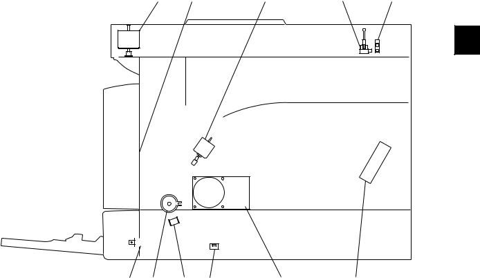
2. Rear side
|
M1 |
M5 |
M2 |
S2 |
S1 |
|
SOL2 CLT1 SOL1 SW5 |
M3 |
M6 |
Fig. 2-2
|
M1 |
Scan motor |
|
M2 |
Toner motor |
|
M3 |
Main motor |
|
M5 |
Exhaust fan |
|
M6 |
Switching regulator cooling fan |
|
S1 |
CIS home position sensor |
|
S2 |
Platen sensor |
|
SW5 |
Drawer detection switch |
|
CLT1 |
Registration clutch |
|
SOL1 |
Pickup solenoid |
|
SOL2 |
Bypass pickup solenoid |
|
© 2009 TOSHIBA TEC CORPORATION All rights reserved |
e-STUDIO181/211 |
|
OUTLINE OF THE MACHINE |
2 — 3
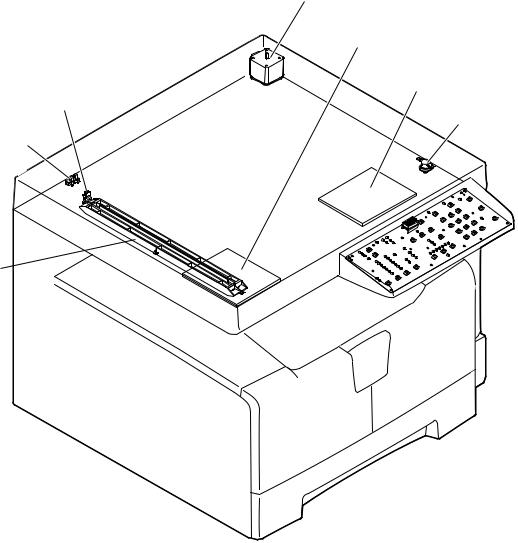
2.2Electric Parts Layout
2.2.1Scanner, control panel
M1
DH1
DH2
S1
THMO2
S2
CIS 

 LPNL
LPNL
Fig. 2-3
|
e-STUDIO181/211 |
© 2009 TOSHIBA TEC CORPORATION All rights reserved |
|
OUTLINE OF THE MACHINE |
2 — 4
![]()
2.2.2Power supply section, switches
SW3
SW2
PS
SW4
SW1
Fig. 2-4
|
© 2009 TOSHIBA TEC CORPORATION All rights reserved |
e-STUDIO181/211 |
|
OUTLINE OF THE MACHINE |
2 — 5

2.2.3Laser optical unit, fuser unit, toner cartridge section
S5
LAMP1
LAMP2
THMO1
THMS1
THMS2
THMS3
Fig. 2-5
|
e-STUDIO181/211 |
© 2009 TOSHIBA TEC CORPORATION All rights reserved |
|
OUTLINE OF THE MACHINE |
2 — 6

2.2.4Developer unit section
ERS
S6
THMS4
FUS
THMO3
DH3
Fig. 2-6
|
© 2009 TOSHIBA TEC CORPORATION All rights reserved |
e-STUDIO181/211 |
|
OUTLINE OF THE MACHINE |
2 — 7

2.2.5Driving section
CLT1
M3
SRAM
MAIN
SOL1
S4
Fig. 2-7
|
e-STUDIO181/211 |
© 2009 TOSHIBA TEC CORPORATION All rights reserved |
|
OUTLINE OF THE MACHINE |
2 — 8

Fig. 2-8
|
© 2009 TOSHIBA TEC CORPORATION All rights reserved |
e-STUDIO181/211 |
|
OUTLINE OF THE MACHINE |
2 — 9

2.2.7Bypass unit
S8
SOL2
Fig. 2-9
|
e-STUDIO181/211 |
© 2009 TOSHIBA TEC CORPORATION All rights reserved |
|
OUTLINE OF THE MACHINE |
2 — 10

2.3Symbols and Functions of Various Components
The column «P-I» shows the page and item number in the parts list. 1. Motors
|
Symbol |
Name |
Function |
Remarks |
P-I |
|
M1 |
SCAN-MOT |
Driving the CIS |
Fig. 2-3 |
10-1 |
|
Scan motor |
||||
|
M2 |
TNR-MOT |
Supplying the toner |
Fig. 2-5 |
12-15 |
|
Toner motor |
||||
|
M3 |
MAIN-MOT |
Driving the drum, developer unit, |
Fig. 2-7 |
12-2 |
|
Main motor |
registration roller, Pickup roller, feed |
|||
|
roller, cleaner unit |
||||
|
M4 |
M/DC-POL |
Driving the polygonal mirror |
Fig. 2-5 |
5-13 |
|
Polygonal motor |
||||
|
M5 |
EXT-FAN-MOT |
Exhausting ozone and cooling down |
Fig. 2-6 |
11-23 |
|
Exhaust fan |
the equipment inside |
|||
|
M6 |
PS-FAN-MOT |
Cooling down the switching regulator |
Fig. 2-4 |
5-11 |
|
Switching regulator cooling fan |
||||
|
© 2009 TOSHIBA TEC CORPORATION All rights reserved |
e-STUDIO181/211 |
|
OUTLINE OF THE MACHINE |
2 — 11
|
2. Sensors and switches |
||||
|
Symbol |
Name |
Function |
Remarks |
P-I |
|
S1 |
HOME-SNR |
Detecting CIS home position |
Fig. 2-3 |
9-101 |
|
CIS home position sensor |
||||
|
S2 |
PLTN-SNR |
Detecting the opening/closing of platen |
Fig. 2-3 |
9-101 |
|
Platen sensor |
cover or RADF |
|||
|
S3 |
TEMP/HUMI-SNR |
Detecting the temperature and humidity |
Fig. 2-4 |
5-16 |
|
Temperature/humidity sensor |
inside the equipment |
|||
|
S4 |
RGST-SNR |
Detecting the transporting paper at the |
Fig. 2-7 |
15-107 |
|
Registration sensor |
registration roller section |
|||
|
S5 |
EXIT-SNR |
Detecting the transporting paper at the |
Fig. 2-5 |
24-8 |
|
Exit sensor |
exit section |
|||
|
S6 |
ATTNR-SNR |
Detecting the density of toner in the |
Fig. 2-6 |
21-46 |
|
Auto-toner sensor |
developer unit |
|||
|
S7 |
EMP-SNR |
Detecting presence/absence of paper |
Fig. 2-8 |
15-107 |
|
Paper empty sensor |
in the drawer |
|||
|
S8 |
SFB-SNR |
Detecting presence/absence of paper |
Fig. 2-9 |
13-101 |
|
Bypass paper sensor |
on the bypass tray |
|||
|
SW1 |
MAIN-SW |
Turning ON/OFF of the equipment |
Fig. 2-4 |
5-4 |
|
Main switch |
||||
|
SW2 |
ADU-COV-INTLCK-SW |
Controlling cutoff and supply of the 24V |
Fig. 2-4 |
6-8 |
|
ADU cover opening/closing interlock |
voltage by opening/closing of the ADU |
|||
|
switch |
cover |
|||
|
SW3 |
FRNT-COV-INTLCK-SW |
Controlling cutoff and supply of the 24V |
Fig. 2-4 |
1-5 |
|
Front cover opening/closing interlock |
voltage by opening/closing of the front |
|||
|
switch |
cover |
|||
|
SW4 |
FRNT-COV-SW |
Detecting the opening/closing of the |
Fig. 2-4 |
1-101 |
|
Front cover opening/closing switch |
front cover |
|||
|
SW5 |
CST-SW |
Detecting presence/absence of the |
Fig. 2-8 |
16-110 |
|
Drawer detection switch |
drawer |
|||
3. Electromagnetic clutches
|
Symbol |
Name |
Function |
Remarks |
P-I |
|
CLT1 |
RGST-CLT |
Driving the registration roller |
Fig. 2-7 |
16-21 |
|
Registration clutch |
||||
4. Solenoids
|
Symbol |
Name |
Function |
Remarks |
P-I |
|
SOL1 |
CST-SOL |
Controlling the power transmission of |
Fig. 2-7 |
16-9 |
|
Pickup solenoid |
the feed roller |
|||
|
SOL2 |
SFB-SOL |
Controlling the power transmission of |
Fig. 2-9 |
14-15 |
|
Bypass pickup solenoid |
the bypass pickup roller |
|||
|
e-STUDIO181/211 |
© 2009 TOSHIBA TEC CORPORATION All rights reserved |
|
OUTLINE OF THE MACHINE |
2 — 12

|
5. |
PC boards |
|||||
|
Symbol |
Name |
Function |
Remarks |
P-I |
||
|
MAIN |
PWA-F-MAIN |
Controlling the whole system and |
Fig. 2-7 |
7-1 |
||
|
Main PC board (MAIN board) |
image processing |
|||||
|
SRAM |
PWA-F-SRAM |
Storing the setting information of the |
Fig. 2-7 |
7-33 |
2 |
|
|
SRAM PC board (SRAM board) |
equipment |
|||||
|
LDR |
PWA-F-LDR |
Driving the laser diode |
Fig. 2-5 |
5-13 |
||
|
Laser driving PC board (LDR board) |
||||||
|
SNS |
PWA-F-SNS |
Detecting the laser beam position |
Fig. 2-5 |
5-13 |
||
|
H-sync signal detection PC board |
||||||
|
(SNS board) |
||||||
|
LPNL |
PWA-F-LPNL |
Detecting the button entry and |
Fig. 2-3 |
4-15 |
||
|
Control panel PC board |
controlling LED on the control panel |
|||||
|
(LPNL board) |
||||||
|
CTIF |
PWA-F-CTIF |
Interface for detecting the toner |
Fig. 2-5 |
7-30 |
||
|
Toner cartridge interface PC board |
cartridge |
|||||
|
(CTIF board) |
(Detecting the CTRG board) |
|||||
|
CTRG |
PWA-F-CTRG |
Storing the status of the toner cartridge |
Fig. 2-5 |
103-3 |
||
|
Toner cartridge PC board |
||||||
|
(CTRG board) |
||||||
|
FUS |
PWA-F-FUS |
Supplying power to each damp heater |
Fig. 2-6 |
7-12 |
||
|
Fuse PC board (FUS board) |
* Optional for NAD/MJD/CND model, |
|||||
|
standard for other models |
6. Lamps and heaters
|
Symbol |
Name |
Function |
Remarks |
P-I |
|
LAMP1 |
CNTR-LAMP |
Heating the center section of the fuser |
Fig. 2-5 |
23-12 |
|
Center heater lamp |
roller |
|||
|
LAMP2 |
SIDE-LAMP |
Heating the section of both sides of the |
Fig. 2-5 |
23-13 |
|
Side heater lamp |
fuser roller |
|||
|
ERS |
LP-ERS |
Removing the residual charge from the |
Fig. 2-6 |
20-13 |
|
Discharge LED |
drum surface |
|||
|
DH1 |
SCN-DH-L |
Preventing condensation in the |
Fig. 2-3 |
9-17 |
|
Scanner damp heater (Left) |
scanner unit |
|||
|
* Optional for NAD/MJD/CND model, |
||||
|
standard for other models |
||||
|
DH2 |
SCN-DH-R |
Preventing condensation in the |
Fig. 2-3 |
9-18 |
|
Scanner damp heater (Right) |
scanner unit |
|||
|
* Optional for NAD/MJD/CND model, |
||||
|
standard for other models |
||||
|
DH3 |
DRM-DH |
Preventing condensation of the drum |
Fig. 2-6 |
8-6 |
|
Drum damp heater |
* Optional for NAD/MJD/CND model, |
|||
|
standard for other models |
||||
|
© 2009 TOSHIBA TEC CORPORATION All rights reserved |
e-STUDIO181/211 |
|
OUTLINE OF THE MACHINE |
2 — 13
7. Thermistors and thermostats
|
Symbol |
Name |
Function |
Remarks |
P-I |
|
THMS1 |
THMS-C-HTR |
Detecting the surface temperature at |
Fig. 2-5 |
23-6 |
|
Center thermistor |
the center of the fuser roller (for |
|||
|
controlling the center heater lamp) |
||||
|
THMS2 |
THMS-S-HTR |
Detecting the surface temperature at |
Fig. 2-5 |
23-6 |
|
Side thermistor |
the rear side of the fuser roller (for |
|||
|
controlling the side heater lamp) |
||||
|
THMS3 |
THMS-EDG-HTR |
Detecting the surface temperature at |
Fig. 2-5 |
23-6 |
|
Edge thermistor |
the edge of the rear side of the fuser |
|||
|
roller (for preventing overheating) |
||||
|
THMS4 |
THMS-DRM |
Detecting the temperature on the drum |
Fig. 2-6 |
21-49 |
|
Drum thermistor |
surface |
|||
|
THMO1 |
THERMO-FSR |
Preventing overheating in the fuser unit |
Fig. 2-5 |
23-5 |
|
Fuser thermostat |
||||
|
THMO2 |
THERMO-SCN-DH |
Preventing overheating of the scanner |
Fig. 2-3 |
9-20 |
|
Scanner damp heater thermostat |
damp heater |
|||
|
* Optional for NAD/MJD/CND model, |
||||
|
standard for other models |
||||
|
THMO3 |
THERMO-DRM-DH |
Preventing overheating of the drum |
Fig. 2-6 |
8-7 |
|
Drum damp heater thermostat |
damp heater |
|||
|
* Optional for NAD/MJD/CND model, |
||||
|
standard for other models |
||||
8. Others
|
Symbol |
Name |
Function |
Remarks |
P-I |
|
CIS |
CIS |
Reading originals |
Fig. 2-3 |
9-8 |
|
Contact image sensor unit |
||||
|
PS |
PS-ACC |
• Generating DC voltage and |
Fig. 2-4 |
5-2 |
|
Switching regulator |
supplying it to each section of the |
|||
|
equipment |
||||
|
• Generating high voltage and |
||||
|
supplying it to the main charger, |
||||
|
developer, transfer and separation |
||||
|
units |
||||
|
• Supplying AC power to the heater |
||||
|
lamp |
||||
|
e-STUDIO181/211 |
© 2009 TOSHIBA TEC CORPORATION All rights reserved |
|
OUTLINE OF THE MACHINE |
2 — 14
![]()
2.4General Description
2.4.1System block diagram
|
Solenoids |
Clutches |
Bypass unit |
||||||||||||||||||||||
|
I/O |
||||||||||||||||||||||||
|
Control panel |
Download JIG |
Sensors |
Switches |
Motors |
PFU |
Copy key card / |
Coin controller |
|||||||||||||||||
|
USB connector (device) |
16 |
SDRAM |
64 MB |
16 |
: Option |
|||||||||||||||||||
|
SRAM |
128 kB |
16 |
8 |
ASIC |
(I/O port) |
|||||||||||||||||||
|
SDRAM bus (16 bit) |
16 |
SDRAM |
16 MB |
SRAM board |
Battery |
CPU bus (16 bit) |
16 |
Flash ROM |
2 MB |
|||||||||||||||
|
SoC |
(System controller) |
|||||||||||||||||||||||
|
8 |
||||||||||||||||||||||||
|
AFE |
Driver |
D/A converter |
A/D converter |
|||||||||||||||||||||
|
MAIN board |
||||||||||||||||||||||||
|
DC |
DC |
(High voltage) |
||||||||||||||||||||||
|
ADF |
CIS |
Scan motor |
M |
Power supply unit |
AC LVPS |
HVPS |
Laser optical unit |
LDR board |
Laser diode ASIC |
SNS board |
Laser beam sensor |
Developer unit |
Auto-toner sensor |
Drum thermistor |
Temperature/humidity |
sensor |
Fuser unit |
Thermistors |
||||||
|
Fig. 2-10 |
|
© 2009 TOSHIBA TEC CORPORATION All rights reserved |
e-STUDIO181/211 |
|
OUTLINE OF THE MACHINE |
2 — 15

2.4.2Construction of boards
[ 1 ] Construction diagram of boards
This system consists of the following including the MAIN board as a main board.
|
Scanner unit |
Control panel |
||||||||||||||
|
CIS |
LPNL |
||||||||||||||
|
Toner cartridge |
|||||||||||||||
|
FUS |
SRAM |
||||||||||||||
|
MAIN |
CTIF |
CTRG |
|||||||||||||
|
HVPS |
|||||||||||||||
|
AC input |
PS-ACC |
Laser optical unit |
|||||||||||||
|
LVPS |
|||||||||||||||
|
LDR |
|||||||||||||||
|
Main switch |
Cover opening/closing |
SNS |
|||||||||||||
|
interlock switches |
|||||||||||||||
|
: DC power supply line |
|||||||||||||||
|
: AC power supply line |
|||||||||||||||
|
: Signal line |
|||||||||||||||
Fig. 2-11
[ 2 ] Function of each board
•MAIN board:
This is the board taking the leading part in all systems. It consists of the SoC, ASIC, memory (SDRAM, Flash ROM), etc. In the SoC (System control), which is a core of this MAIN board, the functions of the CPU, image processing, page memory control, CODEC, external interface (USB) control, etc. are embedded and performed by one chip.
Based on the data input from the control panel, the SoC controls each system, such as the ASIC, each memory, CIS unit and laser optical unit, and thus permitting the scanning of originals and the printing of data.
•SRAM board:
This is the board on which the SRAM for storing the user’s setting information and counter value and its backup function are mounted. When the MAIN board is replaced, attaching this board to the new MAIN board can assume the data of the previous equipment.
•LPNL board:
This is the board on which each button switch and LED on the control panel are mounted.
•CTRG board:
This is the board on which the IC chip for storing information about the toner cartridge (number of prints, identification data, etc.) is mounted.
•CTIF board:
This is the interface board with the CTRG board in the toner cartridge. Information written in the IC chip on the CTRG board is read into the SoC on the MAIN board through this board.
•LDR board:
This is the board on which the laser diode and the ASIC are mounted. The laser is emitted based on the image data signal output from the SoC on the MAIN board.
|
e-STUDIO181/211 |
© 2009 TOSHIBA TEC CORPORATION All rights reserved |
|
OUTLINE OF THE MACHINE |
2 — 16

|
• |
SNS board: |
|
|
This is the board on which the light sensor for detecting the radiating position of the laser is |
||
|
mounted. It outputs the H-sync signal to the SoC on the MAIN board. |
||
|
• |
PS-ACC: |
|
|
This is the unit to generate each DC (high/low) voltage, which is used in the equipment, from the |
2 |
|
|
external AC electric power input. This is then provided to each electric part. |
||
•FUS board:
This is the board to provide AC electric power for driving the damp heater.
*Optional for NAD/MJD/CND model, standard for other models.
•CIS:
This is the unit witch performs optical-to-electrical conversion to convert the light reflected by the original into the electrical signals. It consists of a light source (LEDs), optical system, CCD sensor, etc.
|
© 2009 TOSHIBA TEC CORPORATION All rights reserved |
e-STUDIO181/211 |
|
OUTLINE OF THE MACHINE |
2 — 17

2.5Disassembly and Replacement of Covers
2.5.1Front cover
(1)Open the front cover.
(2)Release the upper hinge.
(3)Take off the front cover while lifting it up.
2.5.2Inner tray
|
(1) Remove 2 screws and take off the Inner tray. |
Inner tray |
|
Fig. 2-13 |
2.5.3Left cover
(1)Take off the Inner tray.
P.2-18 «2.5.2 Inner tray»
(2)Remove 4 screws and take off the left cover.
|
e-STUDIO181/211 |
© 2009 TOSHIBA TEC CORPORATION All rights reserved |
|
OUTLINE OF THE MACHINE |
2 — 18

2.5.4Tray rear cover
(1)Take off the left cover.
P.2-18 «2.5.3 Left cover»
(2)Take off the tray rear cover.
|
2 |
Tray rear cover |
|
Fig. 2-15 |
2.5.5Front right cover
(1)Take off the front cover.
P.2-19 «2.5.5 Front right cover»
(2)Pull out the toner cartridge.
(3)Open the ADU cover.
(4)Remove 2 screws and take off the front right cover.
Front right cover
Fig. 2-16
2.5.6Front upper cover
(1)Remove 1 screw and take off the front upper cover.
Front upper cover |
|
Fig. 2-17 |
|
© 2009 TOSHIBA TEC CORPORATION All rights reserved |
e-STUDIO181/211 |
|
OUTLINE OF THE MACHINE |
2 — 19

2.5.7ADU cover
(1)Open the bypass tray.
(2)Open the ADU cover.
(3)Open the transfer unit and release the ADU stopper on the front side.
(4)Remove 1 screw and take off the ADU stopper on the rear side.
Note:
Be careful not to fall off the ADU cover when the screws are removed from the ADU stopper.
(5)Take off the ADU cover while sliding it toward the right.
|
ADU stopper |
ADU stopper |
|
Fig. 2-18 |
2.5.8Right front cover
(1)Take off the front cover.
P.2-18 «2.5.1 Front cover»
(2)Open the ADU cover.
(3)Pull out the drawer.
(4)Remove 2 screws and take off the right front cover.
Right front cover |
|
Fig. 2-20 |
|
e-STUDIO181/211 |
© 2009 TOSHIBA TEC CORPORATION All rights reserved |
|
OUTLINE OF THE MACHINE |
2 — 20

2.5.9Right rear cover
(1)Open the ADU cover.
(2)Remove 1 screw and take off the ADU stopper on the rear side.
(3)Take off the 2 screw and take off the right rear cover.
|
2 |
Right rear cover |
|
Fig. 2-21 |
2.5.10Rear cover
(1)Remove 5 screws and take off the rear cover.
|
© 2009 TOSHIBA TEC CORPORATION All rights reserved |
e-STUDIO181/211 |
|
OUTLINE OF THE MACHINE |
2 — 21

2.6Disassembly and Replacement of PC boards
Note:
If the PC board has to be replaced due to an operational defect, this may have been caused by a contact failure of the connector. Before replacing the board, disconnect and then reconnect the connector to check if this action eliminates the operational defect.
2.6.1MAIN board (MAIN)
(1) Take off the rear cover.
P.2-21 «2.5.10 Rear cover»
(2) Disconnect 15 connectors.
Note:
Connect the flat harness to the MAIN board with its erectrode side down. An error “CA2” will be displayed if the connection is incorrect.
Fig. 2-23
(3) Remove 6 screws and take off the MAIN board.
Notes:
1. When replacing the MAIN board, also attach the SRAM board to the new MAIN board from the old MAIN board.
2. Be sure to perform “08-389” after the SRAM board has been replaced.
3. Be sure to perform «05-310» with the platen cover or the ADF closed after replacing the MAIN board.
MAIN board
Fig. 2-24
|
e-STUDIO181/211 |
© 2009 TOSHIBA TEC CORPORATION All rights reserved |
|
OUTLINE OF THE MACHINE |
2 — 22

2.6.2SRAM board (SRAM)
(1)Take off the rear cover.
|
P.2-21 «2.5.10 Rear cover» |
|
|
(2) Release 1 lock support and take off the |
2 |
|
SRAM board. |
|
|
Notes: |
SRAM board |
|
1. Be sure to perform “08-388” after the |
|
|
SRAM board has been replaced. |
|
|
2. Perform «05-310» with the platen cover |
|
|
and the ADF closed after replacing the |
|
|
SRAM board. |
3.Make sure that the direction of the battery on the SRAM board is correct when replacing it.
|
Fig. 2-25 |
|
SRAM board |
|
Battery |
|
Fig. 2-26 |
|
© 2009 TOSHIBA TEC CORPORATION All rights reserved |
e-STUDIO181/211 |
|
OUTLINE OF THE MACHINE |
2 — 23

2.6.3Fuse PC board (FUS)
Note:
This fuse PC board is copacked with the damp heater unit. (The damp heater unit is optional for NAD, CND and MJD.)
(1)Take off the rear cover.
P.2-21 «2.5.10 Rear cover»
(2)Remove 2 screws and take off the cover.
(3)Disconnect 2 connectors, remove 1 screw, and then take off the fuse PC board by lifting it up.
|
Connector |
|
Fuse PC board |
|
Fig. 2-28 |
2.6.4Switching regulator unit (PS)
|
Note: |
|
|
When the fuse PC board is installed as |
|
|
options, remove the rear cover ( |
P.2-21 |
|
«2.5.10 Rear cover») and disconnect |
|
|
connectors before performing the |
|
|
procedure below. |
|
|
Connector |
|
|
Fig. 2-29 |
|
e-STUDIO181/211 |
© 2009 TOSHIBA TEC CORPORATION All rights reserved |
|
OUTLINE OF THE MACHINE |
2 — 24
Loading…