-
Contents
-
Table of Contents
-
Troubleshooting
-
Bookmarks
Quick Links
Business Networking Solution
Installation Guide
16-Port 10/100Mbps + 2-Port Gigabit Unmanaged PoE Switch
TL-SL1218MP
Related Manuals for TP-Link TL-SL1218MP
Summary of Contents for TP-Link TL-SL1218MP
-
Page 1
Business Networking Solution Installation Guide 16-Port 10/100Mbps + 2-Port Gigabit Unmanaged PoE Switch TL-SL1218MP… -
Page 3
Conventions • Some models featured in this guide may be unavailable in your country or region. For local sales information, visit https://www.tp-link.com. • The figures in Chapter 2 to Chapter 3 are for demonstration purposes only. Your switch may differ in appearance from that depicted. -
Page 4: Table Of Contents
Contents Chapter 1 Introduction ——————————— 1 Product Overview …………1 Appearance ……………1 Chapter 2 Installation ——————————— 4 Package Contents …………4 Safety Precautions …………4 Installation Tools …………..6 Product Installation …………6 Chapter 3 Connection ——————————— 8 Ethernet Port …………..8 SFP Port …………….8 Verify Installation ………….8 Power On …………….9 Initialization …………….9 Appendix A Troubleshooting ————————…
-
Page 5: Chapter 1 Introduction
TL-SL1218MP is a 16-Port 10/100Mbps + 2-Port Gigabit Unmanaged Switch that requires no configuration. TL-SL1218MP is also a Power Sourcing Equipment (PSE*). 16 of the RJ45 ports on the switch support Power over Ethernet (PoE*) function, which can automatically detect and supply power for those powered devices (PDs*) complying with IEEE 802.3af and IEEE 802.3at.
-
Page 6
16-Port 10/100Mbps + 2-Port Gigabit Unmanaged PoE Switch Indication For Port 1-16: On: Running at 10/100Mbps but no activity. Flashing: Running at 10/100Mbps and is transmitting or receiving data. Off: No device is linked to the corresponding port. For Port 17/17F-18/18F: Link/Act Green On: Running at 1000Mbps but no activity. -
Page 7
The switch already comes with lightning protection mechanism. You can also ground the switch through the PE (Protecting Earth) cable of AC cord or with Ground Cable. For detailed information, please refer to the Lightning Protection Guide from the training center of our website: https://www.tp-link.com/en/configuration-guides/lightning_protection_guide/?configurationId=2962 Introduction… -
Page 8: Chapter 2 Installation
16-Port 10/100Mbps + 2-Port Gigabit Unmanaged PoE Switch Chapter 2 Installation Package Contents Make sure that the package contains the following items. If any of the listed items is damaged or missing, please contact your distributor. One Switch One Power Cord This Installation Guide Two mounting brackets and the fittings…
-
Page 9
16-Port 10/100Mbps + 2-Port Gigabit Unmanaged PoE Switch Please keep a proper temperature and humidity in the equipment room. Too high/low humidity may lead to bad insulation, electricity leakage, mechanical property changes and corrosions. Too high temperature may accelerate aging of the insulation materials and can thus significantly shorten the service life of the device. -
Page 10: Installation Tools
Note: For detailed lightning protection measures, please refer to the Lightning Protection Guide from the training center of our website: https://www.tp-link.com/en/configuration-guides/lightning_protection_guide/?configurationId=2962 Installation Site When installing the device on a rack or a flat workbench, please note the following items: The rack or workbench is flat and stable, and sturdy enough to support the weight of 5.5kg at least.
-
Page 11
16-Port 10/100Mbps + 2-Port Gigabit Unmanaged PoE Switch Rack Installation ■ To install the device in an EIA standard-sized, 19-inch rack, follow the instructions described below: 1. Check the grounding and stability of the rack. 2. Secure the supplied rack-mounting brackets to each side of the device with supplied screws, as illustrated in the following figure. -
Page 12: Chapter 3 Connection
16-Port 10/100Mbps + 2-Port Gigabit Unmanaged PoE Switch Chapter 3 Connection Ethernet Port Connect an Ethernet port of the switch to the computer by RJ45 cable as the following figure shows. Figure 3-1 Connecting the RJ45 Port RJ45 Port RJ45 Cable SFP Port The following figure demonstrates the connection of SFP port to an SFP module.
-
Page 13: Power On
16-Port 10/100Mbps + 2-Port Gigabit Unmanaged PoE Switch Power On Plug in the negative connector of the provided power cord into the power socket of the device, and the positive connector into a power outlet as the following figure shows. Figure 3-3 Connecting to Power Supply 100 -24…
-
Page 14: Appendix A Troubleshooting
16-Port 10/100Mbps + 2-Port Gigabit Unmanaged PoE Switch Appendix A Troubleshooting Q1. Why is the PWR LED not lit? The PWR LED should be lit when the power system is working normally. If the PWR LED is not lit, please check as follows: A1: Make sure the switch is connected to the power source with the AC power cord properly.
-
Page 15: Appendix B Specifications
16-Port 10/100Mbps + 2-Port Gigabit Unmanaged PoE Switch Appendix B Specifications Standard IEEE802.3i, 802.3u, 802.3ab, 802.3z, 802.3af, 802.3at, 802.3x Protocol CSMA/CD 16 10/100Mbps RJ45 Ports (Auto-Negotiation/Auto MDI/MDIX) Interface 2 10/100/1000Mbps RJ45 Ports (Auto-Negotiation/Auto MDI/MDIX) 2 1000Mbps SFP Slots (Combo) Port Standard 10BASE-T: UTP category 3, 4, 5 cable 100BASE-TX/1000Base-T: UTP category 5, 5e or above cable 1000BASE-X: MMF, SMF…
-
Page 16
Any changes or modifications not expressly approved by the party responsible for compliance could void the user’s authority to operate the equipment. We, TP-Link USA Corporation, has determined that the equipment shown as above has been shown to comply with the applicable technical standards, FCC part 15. There is no unauthorized change is made in the equipment and the equipment is properly maintained and operated. -
Page 17
Safety Information • Keep the device away from water, fire, humidity or hot environments. • Do not attempt to disassemble, repair, or modify the device. • Do not use damaged charger or USB cable to charge the device. Please read and follow the above safety information when operating the device. We cannot guarantee that no accidents or damage will occur due to improper use of the device. -
Page 18
Explanation of the symbols on the product label Symbol Explanation AC voltage Indoor use only RECYCLING This product bears the selective sorting symbol for Waste electrical and electronic equipment (WEEE). This means that this product must be handled pursuant to European directive 2012/19/EU in order to be recycled or dismantled to minimize its impact on the environment. -
Page 20
For technical support, User Guide and other information, please visit https://www.tp-link.com/support, or simply scan the QR code. © 2018 TP-Link 7106508198 REV1.0.0…
Displayed below is the user manual for TL-SL1218MP by TP-Link which is a product in the Network Switches category.
This manual has pages.

Business Networking Solution
Installation Guide
TL-SL1218MP
16-Port 10/100Mbps + 2-Port Gigabit Unmanaged PoE Switch

About this Installation Guide
This Installation Guide describes the hardware characteristics, installation methods and the
points that should be attended to during installation. This Installation Guide is structured as
follows:
Chapter 1 Introduction
This chapter describes the external components of the switch.
Chapter 2 Installation
This chapter illustrates how to install the switch.
Chapter 3 Connection
This chapter illustrates how to do the physical connection of the switch.
Appendix A Troubleshooting
Appendix B Hardware Specifications
Audience
This Installation Guide is for:
Network Engineer Network Administrator
Conventions
• Some models featured in this guide may be unavailable in your country or region. For local sales
information, visit https://www.tp-link.com.
• The figures in Chapter 2 to Chapter 3 are for demonstration purposes only. Your switch may differ
in appearance from that depicted.
• This Guide uses the specific formats to highlight special messages. The following table lists the
notice icons that are used throughout this guide.
Remind to be careful. A caution indicates a potential which may result in device damage.
Remind to take notice. The note contains the helpful information for a better use of the
product.
Related Document
This Installation Guide is also available in PDF on our website. To obtain the latest
documentation and product information, please visit the official website:
https://www.tp-link.com

Contents
Chapter 1 Introduction ——————————— 1
1.1 Product Overview …………………………………………………..1
1.2 Appearance ……………………………………………………………..1
Chapter 2 Installation ——————————— 4
2.1 Package Contents ………………………………………………….4
2.2 Safety Precautions …………………………………………………4
2.3 Installation Tools ……………………………………………………..6
2.4 Product Installation ………………………………………………..6
Chapter 3 Connection ——————————— 8
3.1 Ethernet Port …………………………………………………………..8
3.2 SFP Port ……………………………………………………………………8
3.3 Verify Installation …………………………………………………….8
3.4 Power On ………………………………………………………………….9
3.5 Initialization ………………………………………………………………9
Appendix A Troubleshooting ———————— 10
Appendix B Specications ————————— 11
1
16—Port 10/100Mbps + 2-Port Gigabit Unmanaged PoE Switch
Introduction
Chapter 1 Introduction
1.1 Product Overview
TL-SL1218MP is a 16-Port 10/100Mbps + 2-Port Gigabit Unmanaged Switch that requires no
configuration. TL-SL1218MP is also a Power Sourcing Equipment (PSE*). 16 of the RJ45 ports on
the switch support Power over Ethernet (PoE*) function, which can automatically detect and supply
power for those powered devices (PDs*) complying with IEEE 802.3af and IEEE 802.3at.
Note:
■*PSE is a device (switch or hub for instance) that will provide power in a PoE setup.
■*PoE is a technology that describes a system to transmit electrical power, along with data, to
remote devices over standard twisted-pair cable in an Ethernet network.
■*PD is a device powered by a PSE and thus consumes energy. Examples include powering
IP telephones, wireless LAN access points, network cameras, network hubs, embedded
computers and so on.
1.2 Appearance
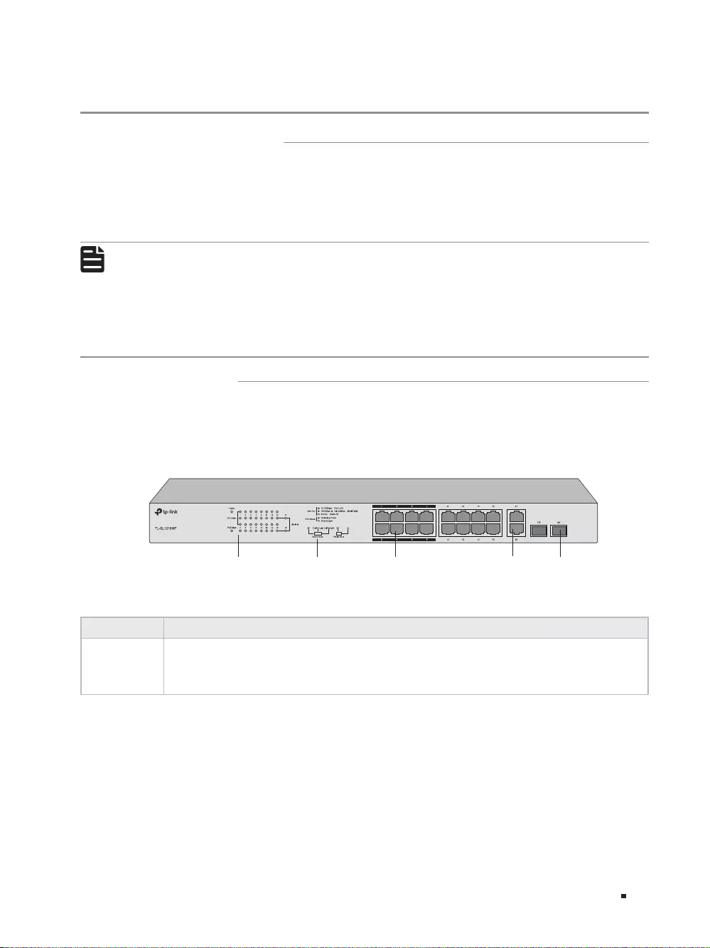
■Front Panel
The front panel of TL—SL1218MP is shown as the following figure.
Figure 1-1 Front Panel of TL—SL1218MP
10/100Mbps
RJ45 Port (Port 1-16)
LEDs Switches 10/100/1000Mbps
RJ45 Port (Port 17-18)
SFP Port
(Port 17F-18F)
LEDs
LED Indication
PWR On: The switch is powered on.
Off: The switch is powered off.

2
16—Port 10/100Mbps + 2-Port Gigabit Unmanaged PoE Switch
Introduction
LED Indication
Link/Act
For Port 1-16:
On: Running at 10/100Mbps but no activity.
Flashing: Running at 10/100Mbps and is transmitting or receiving data.
Off: No device is linked to the corresponding port.
For Port 17/17F-18/18F:
Green On: Running at 1000Mbps but no activity.
Green Flashing: Running at 1000Mbps and is transmitting or receiving data.
Yellow On: Running at 10/100Mbps but no activity.
Yellow Flashing: Running at 10/100Mbps and is transmitting or receiving data.
Off: No device is linked to the corresponding port.
PoE Status
On: The port is connecting to a PD and supplying power for it.
Flashing: The PoE power circuit may be in short or the power current may be overloaded.
Off: No PD is connected to the corresponding port, or no power is supplied according to
the power limits of the port.
PoE Max
On: Total power supply ≥ 185W.
Flashing: Total power supply ≥ 185W and last for more than 2 minutes.
Off: Total power supply ≤ 185W.
Switches
Switch Indication
Extend Mode
Off: Port 1-16 run at 10/100 Mbps and support PoE power supply up to 100m away.
On (Port1-8): Port 1—8 run at 10 Mbps and support PoE power supply up to 250m away.
On (Port1-16): Port 1-16 run at 10 Mbps and support PoE power supply up to 250m away.
Priority Mode
Off: All the ports transmit data in the same priority.
On: Port 1-8 transmit data in a higher priority than Port 9—18. When congestion occurs,
packets which are transmitted by the ports with higher priority occupy the whole
bandwidth.
10/100Mbps RJ45 Port (Port 1-16)
The ports are designed to connect to devices with a bandwidth of 10Mbps or 100Mbps. The ports can
provide power and transmit data for PDs. The maximum PoE power is 30W for each PoE port and 192W
for all the PoE ports. The ports can also connect to non-PoE devices, but only transmit data.
10/100/1000Mbps RJ45 Port (Port 17—18)
The ports are designed to connect to devices with a bandwidth of 10Mbps, 100Mbps or 1000Mbps.
SFP Port (Port 17F—18F)
The ports are designed to install the SFP module. An SFP Port (Port 17F-18F) and the associated
10/100/1000Mbps RJ45 Port (Port 17-18) are called a “Combo” port, which means they cannot be used
simultaneously, otherwise only the SFP port works.
3
16—Port 10/100Mbps + 2-Port Gigabit Unmanaged PoE Switch
Introduction
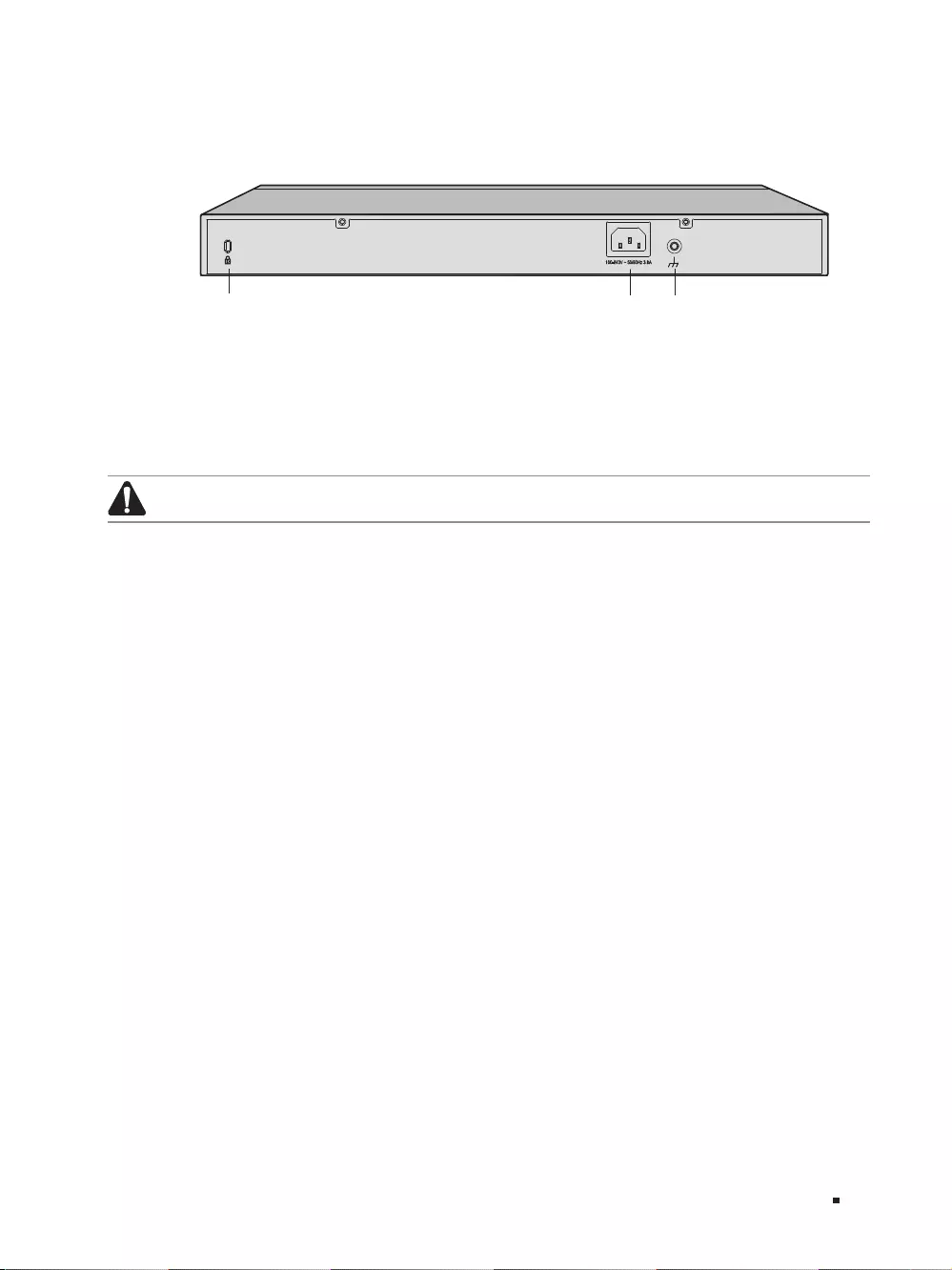
■Rear Panel
The rear panel is shown as the following figure.
Figure 1-2 Rear Panel
Kensington Security Slot Power Socket Grounding Terminal
Kensington Security Slot
Secure the lock (not provided) into the security slot to prevent the device from being stolen.
Power Socket
Connect the female connector of the power cord here, and the male connector to the AC power outlet.
Please make sure the voltage of the power supply meets the requirement of the input voltage (100-240V~
50/60Hz).
Note:
Please use the provided power cord.
Grounding Terminal
The switch already comes with lightning protection mechanism. You can also ground the
switch through the PE (Protecting Earth) cable of AC cord or with Ground Cable. For detailed
information, please refer to the Lightning Protection Guide from the training center of our website:
https://www.tp-link.com/en/conguration-guides/lightning_protection_guide/?congurationId=2962
4
16—Port 10/100Mbps + 2-Port Gigabit Unmanaged PoE Switch
Installation
Chapter 2 Installation
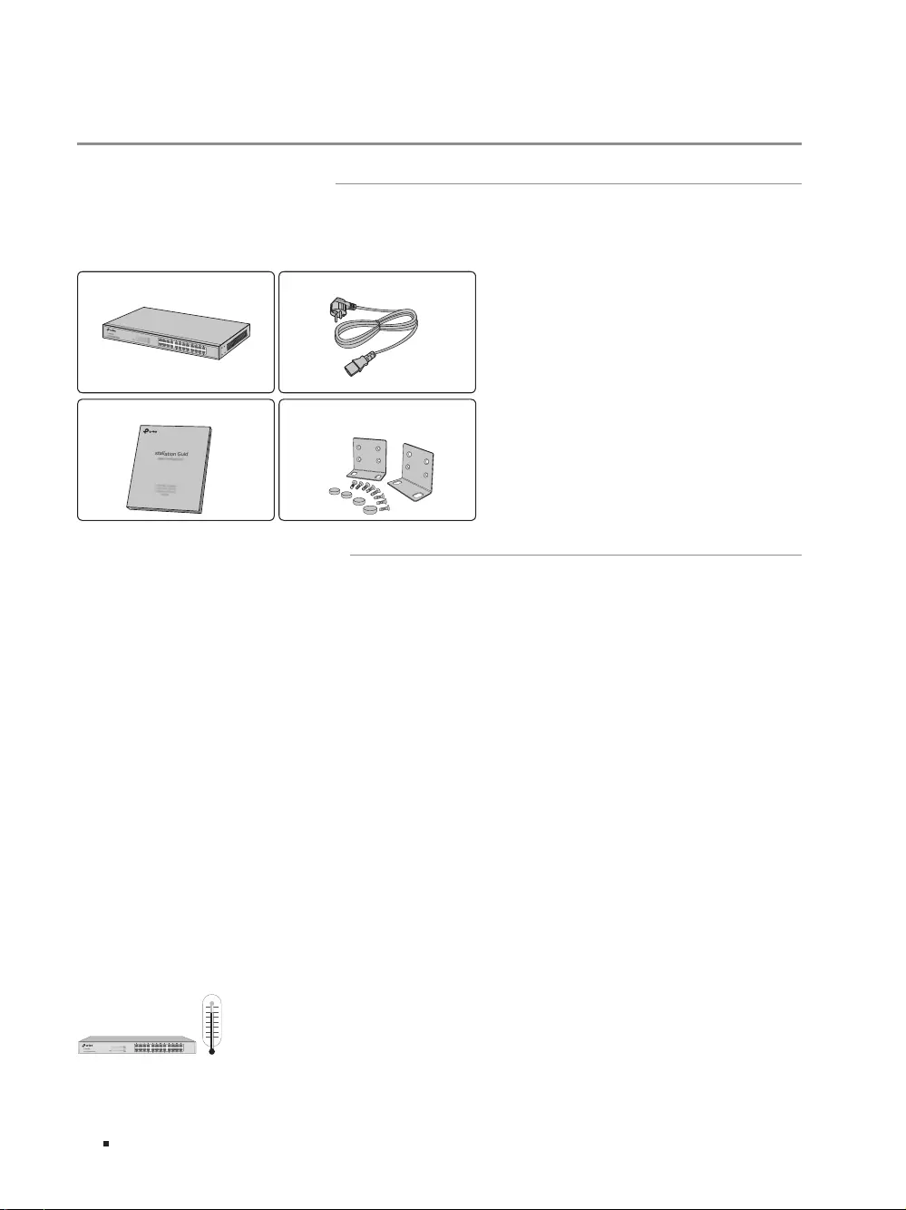
2.1 Package Contents
Make sure that the package contains the following items. If any of the listed items is damaged or
missing, please contact your distributor.
One Switch One Power Cord
Two mounting brackets and the
ttings
This Installation Guide
Installation Guide
Business Networking Solution
2.2 Safety Precautions
To avoid any device damage and bodily injury caused by improper use, please observe the following
rules.
■Safety Precautions
■Keep the power off during the installation.
■Wear an ESD-preventive wrist strap, and make sure that the wrist strap has a good skin contact and is
well grounded.
■Use only the power cord provided with the switch.
■Make sure that the supply voltage matches the specifications indicated on the rear panel of the
switch.
■Ensure the vent hole is well ventilated and unblocked.
■Do not open or remove the cover of the switch.
■Before cleaning the device, cut off the power supply. Do not clean it by the waterish cloth, and never
use any other liquid cleaning method.
■Place the device with its bottom surface downward.
■Site Requirements
Temperature/Humidity
0℃
5
16—Port 10/100Mbps + 2-Port Gigabit Unmanaged PoE Switch
Installation
Please keep a proper temperature and humidity in the equipment room. Too high/low humidity may
lead to bad insulation, electricity leakage, mechanical property changes and corrosions. Too high
temperature may accelerate aging of the insulation materials and can thus significantly shorten
the service life of the device. For normal temperature and humidity of the device, please check the
following table.
Environment Temperature Humidity
Operating 0℃ to 50℃10% to 90%RH Non-condensing
Storage -40℃ to 70℃5% to 90%RH Non-condensing
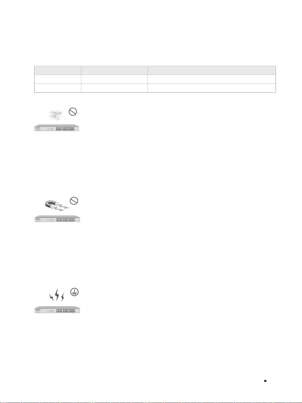
Clearness
The dust accumulated on the switch can be absorbed by static electricity and result in poor contact
of metal contact points. Some measures have been taken for the device to prevent static electricity,
but too strong static electricity can cause deadly damage to the electronic elements on the internal
circuit board. To avoid the effect of static electricity on the operation of the switch, please attach
much importance to the following items:
■Dust the device regularly, and keep the indoor air clean.
■Keep the device well grounded and ensure static electricity has been transferred.
Electromagnetic Interference
Electronic elements including capacitance and inductance on the device can be affected by
external interferences, such as conducted emission by capacitance coupling, inductance coupling,
and impedance coupling. To decrease the interferences, please make sure to take the following
measures:
■Use the power supply that can effectively filter interference from the power grid.
■Keep the device far from high-frequency, strong-current devices, such as radio transmitting station.
■Use electromagnetic shielding when necessary.
Lightning Protection
Extremely high voltage currents can be produced instantly when lightning occurs and the air in
the electric discharge path can be instantly heated up to 20,000℃. As this instant current is strong
enough to damage electronic devices, more effective lightning protection measures should be
taken.
■Ensure the rack and device are well earthed.
■Make sure the power socket has a good contact with the ground.
6
16—Port 10/100Mbps + 2-Port Gigabit Unmanaged PoE Switch
Installation
■Keep a reasonable cabling system and avoid induced lightning.
■Use the signal SPD (Surge Protective Device) when wiring outdoor.
Note:
For detailed lightning protection measures, please refer to the Lightning Protection Guide
from the training center of our website:
https://www.tp-link.com/en/conguration-guides/lightning_protection_guide/?congurationId=2962
Installation Site
When installing the device on a rack or a flat workbench, please note the following items:
■The rack or workbench is flat and stable, and sturdy enough to support the weight of 5.5kg at least.
■The rack or workbench has a good ventilation system. The equipment room is well ventilated.
■The rack is well grounded. Keep the power socket less than 1.5 meters away from the device.
2.3 Installation Tools
■Phillips screwdriver
■ESD-preventive wrist wrap
■Cables
Note:
These tools are not provided with our product. If needed, please self purchase them.
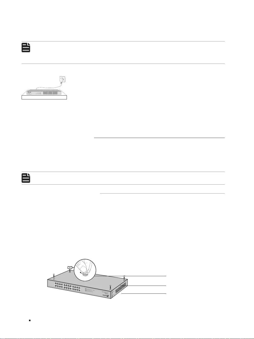
2.4 Product Installation
■Desktop Installation
To install the device on the desktop, please follow the steps:
1. Set the device on a flat surface strong enough to support the entire weight of the device with all
fittings.
2. Remove the adhesive backing papers from the rubber feet.
3. Turnover the device and attach the supplied rubber feet to the recessed areas on the bottom at
each corner of the device.
Figure 2-1 Desktop Installation
Feet
Bottom of the Device
Notch
7
16—Port 10/100Mbps + 2-Port Gigabit Unmanaged PoE Switch
Installation
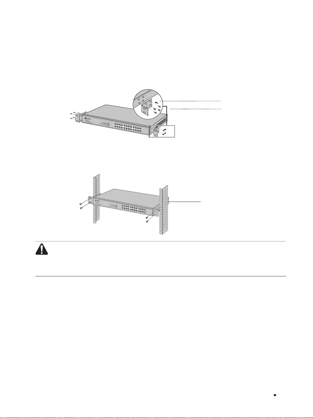
■Rack Installation
To install the device in an EIA standard—sized, 19-inch rack, follow the instructions described below:
1. Check the grounding and stability of the rack.
2. Secure the supplied rack-mounting brackets to each side of the device with supplied screws, as
illustrated in the following figure.
Figure 2-2 Bracket Installation
Rack-mounting Bracket
Screw
3. After the brackets are attached to the device, use suitable screws (not provided) to secure the
brackets to the rack, as illustrated in the following figure.
Figure 2-3 Rack Installation
Rack
Caution:
■Please set 5 to 10cm gaps around the device for air circulation.
■Please avoid any heavy thing placed on the device.
■Please mount devices in sequence from the bottom to top of the rack and ensure a certain
clearance between devices for the purpose of heat dissipation.
8
16—Port 10/100Mbps + 2-Port Gigabit Unmanaged PoE Switch
Connection
Chapter 3 Connection
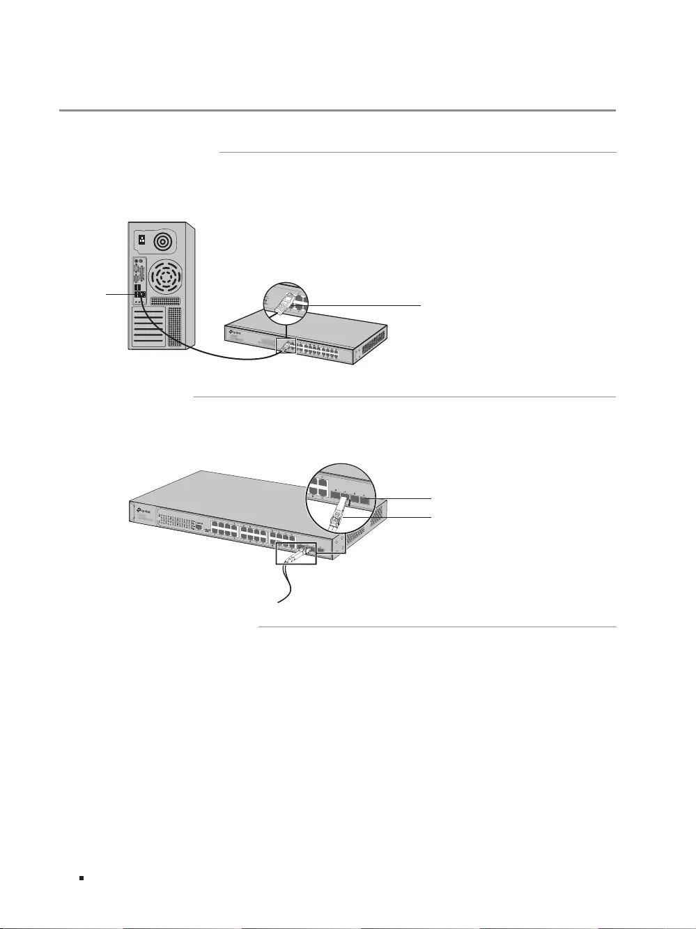
3.1 Ethernet Port
Connect an Ethernet port of the switch to the computer by RJ45 cable as the following figure shows.
Figure 3-1 Connecting the RJ45 Port
RJ45 Port
RJ45 Cable
3.2 SFP Port
The following figure demonstrates the connection of SFP port to an SFP module.
Figure 3-2 Inserting the SFP Module
SFP Slot
SFP Module
3.3 Verify Installation
After completing the installation, please verify the following items:
■There are 5 to 10cm of clearance around the sides of the device for ventilation and the air flow is
adequate.
■The voltage of the power supply meets the requirement of the input voltage of the device.
■The power socket, device and rack are well grounded.
■The device is correctly connected to other network devices.
9
16—Port 10/100Mbps + 2-Port Gigabit Unmanaged PoE Switch
Connection
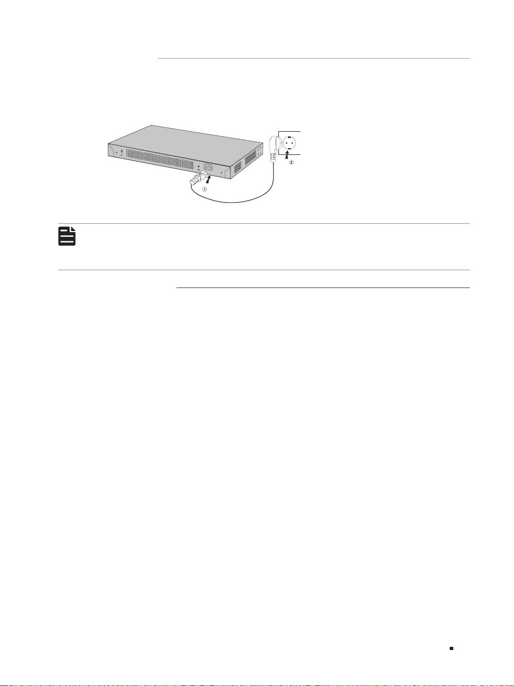
3.4 Power On
Plug in the negative connector of the provided power cord into the power socket of the device, and
the positive connector into a power outlet as the following figure shows.
Figure 3-3 Connecting to Power Supply
100-240V~50/60Hz 0.5A
Note:
The figure is to illustrate the application and principle. The power plug you get from the
package and the socket in your situation will comply with the regulation in your country, so
they may dier from the gure above.
3.5 Initialization
After the device is powered on, it begins the Power-On Self-Test. A series of tests run automatically
to ensure the device functions properly. During this time, the LED indicators will respond as follows:
1. The PWR LED indicator will light up and keep on.
2. After the initialization, the Link/Act LED indicator for Port 17/17F-18/18F will first turn green, then
turn yellow and finally turn off again.
3. After the initialization, the other LED indicators will flash momentarily and then turn off again.

10 Appendix A Troubleshooting
16—Port 10/100Mbps + 2-Port Gigabit Unmanaged PoE Switch
Appendix A Troubleshooting
Q1. Why is the PWR LED not lit?
The PWR LED should be lit when the power system is working normally. If the PWR LED is not lit,
please check as follows:
A1: Make sure the switch is connected to the power source with the AC power cord properly.
A2: Make sure the voltage of the power supply meets the requirements of the input voltage of the
switch.
A3: Make sure the power source is on.
Q2. Why is the Link/Act LED not lit when a device is connected to the corresponding port?
It is recommended that you check the following items:
A1: Make sure that the cable connectors are firmly plugged into the switch and the device.
A2: Make sure the connected device is turned on and working well.
Q3. Why are port 7-16 not supplying power for PoE devices?
If total power consumption of connected PoE devices exceeds 192W, the system will cut off the
power to ports with larger serial numbers to compensate for the overload. For example, port 1-5
and port 7 are consuming 30W respectively, if an additional PoE device with 25W is inserted to
port 6, the system will cut off the power to port 7.

11
Appendix B Specications
16—Port 10/100Mbps + 2-Port Gigabit Unmanaged PoE Switch
Appendix B Specifications
Standard IEEE802.3i, 802.3u, 802.3ab, 802.3z, 802.3af, 802.3at, 802.3x
Protocol CSMA/CD
Interface
16 10/100Mbps RJ45 Ports
(Auto-Negotiation/Auto MDI/MDIX)
2 10/100/1000Mbps RJ45 Ports
(Auto-Negotiation/Auto MDI/MDIX)
2 1000Mbps SFP Slots (Combo)
Port Standard 10BASE-T: UTP category 3, 4, 5 cable
100BASE-TX/1000Base-T: UTP category 5, 5e or above cable
1000BASE-X: MMF, SMF
PoE Port (RJ45) PoE Port: Port 1-16
Total Power Supply: 192W
Switching Capacity 7.2Gbps
Mac Address Table 8K
Transfer Method Store-and-Forward
Power Supply 100~240V AC, 50/60Hz
Fan Quantity 2
Operating Temperature 0℃ to 50℃ (32℉ to 122℉)
Storage Temperature -40℃ to 70℃ (-40℉ to 158℉)
Operating Humidity 10% to 90%RH Non-condensing
Storage Humidity 5% to 90%RH Non-condensing

FCC STATEMENT
Product Name: 16-Port 10/100Mbps + 2-Port Gigabit Unmanaged PoE Switch
Model Number: TL-SL1218MP
Responsible party:
TP-Link USA Corporation, d/b/a TP-Link North America, Inc.
Address: 145 South State College Blvd. Suite 400, Brea, CA 92821
Website: http://www.tp-link.com/us/
Tel: +1 626 333 0234
Fax: +1 909 527 6803
E-mail: sales.usa@tp-link.com
This equipment has been tested and found to comply with the limits for a Class A digital device,
pursuant to part 15 of the FCC Rules. These limits are designed to provide reasonable protection
against harmful interference when the equipment is operated in a commercial environment. This
equipment generates, uses, and can radiate radio frequency energy and, if not installed and used in
accordance with the instruction manual, may cause harmful interference to radio communications.
Operation of this equipment in a residential area is likely to cause harmful interference in which case
the user will be required to correct the interference at his own expense.
This device complies with part 15 of the FCC Rules. Operation is subject to the following two
conditions:
1) This device may not cause harmful interference.
2) This device must accept any interference received, including interference that may cause
undesired operation.
Any changes or modifications not expressly approved by the party responsible for compliance could
void the user’s authority to operate the equipment.
We, TP-Link USA Corporation, has determined that the equipment shown as above has been shown
to comply with the applicable technical standards, FCC part 15. There is no unauthorized change is
made in the equipment and the equipment is properly maintained and operated.
Issue Date: 2018/10/31
CE Mark Warning
This is a class A product. In a domestic environment, this product may cause radio interference, in
which case the user may be required to take adequate measures.
TP-Link hereby declares that the device is in compliance with the essential requirements and
other relevant provisions of directives 2014/30/EU, 2014/35/EU, 2009/125/EC and 2011/65/EU.
The original EU declaration of conformity may be found at http://www.tp—link.com/en/ce

Safety Information
• Keep the device away from water, fire, humidity or hot environments.
• Do not attempt to disassemble, repair, or modify the device.
• Do not use damaged charger or USB cable to charge the device.
Please read and follow the above safety information when operating the device. We cannot
guarantee that no accidents or damage will occur due to improper use of the device. Please use this
product with care and operate at your own risk.
BSMI Notice
安全諮詢及注意事項
• 請使用原裝電源供應器或只能按照本產品注明的電源類型使用本產品。
• 清潔本產品之前請先拔掉電源線。請勿使用液體、噴霧清潔劑或濕布進行清潔。
• 注意防潮,請勿將水或其他液體潑灑到本產品上。
• 插槽與開口供通風使用,以確保本產品的操作可靠並防止過熱,請勿堵塞或覆蓋開口。
• 請勿將本產品置放於靠近熱源的地方。除非有正常的通風,否則不可放在密閉位置中。
• 請不要私自打開機殼,不要嘗試自行維修本產品,請由授權的專業人士進行此項工作。
此為甲類資訊技術設備,于居住環境中使用時,可能會造成射頻擾動,在此種情況下,使用者會被要求採取某些適
當的對策。
限用物質含有情況標示聲明書
產品元件名稱
限用物質及其化學符號
鉛
Pb
鎘
Cd
汞
Hg
六價鉻
CrVI
多溴聯苯
PBB
多溴二苯醚
PBDE
PCB ○○○○○○
外殼○○○○○○
電源供應板 —○○○○○
備考1. «超出0.1 wt %» 及 «超出0.01 wt %» 系指限用物質之百分比含量超出百分比含量基準值。
備考2. «○«系指該項限用物質之百分比含量未超出百分比含量基準值。
備考3. «
−«系指該項限用物質為排除項目。
Industry Canada Statement
CAN ICES-3 (A)/NMB-3(A)

Explanation of the symbols on the product label
Symbol Explanation
AC voltage
Indoor use only
RECYCLING
This product bears the selective sorting symbol for Waste electrical and
electronic equipment (WEEE). This means that this product must be handled
pursuant to European directive 2012/19/EU in order to be recycled or
dismantled to minimize its impact on the environment.
User has the choice to give his product to a competent recycling organization
or to the retailer when he buys a new electrical or electronic equipment.
この装置は、クラスA情報技術装置です。この装置を家庭環境で使用すると電波妨害を引き起こす
ことがあります。この場合には使用者が適切な対策を講ずるよう要求されることがあります。
VCCI—A


© 2018 TP-Link 7106508198 REV1.0.0
For technical support, User Guide and other information, please visit
https://www.tp-link.com/support, or simply scan the QR code.
![]()
Business Networking Solution
Installation Guide
Unmanaged PoE/PoE+ Switch

About this Installation Guide
This Installation Guide describes the hardware characteristics, installation methods and the points that should be attended to during installation.
This Installation Guide is structured as follows:
Chapter 1 Introduction
This chapter describes the external components of the switch.
Chapter 2 Installation
This chapter illustrates how to install the switch.
Chapter 3 Connection
This chapter illustrates how to do the physical connection of the switch.
Appendix A Troubleshooting Appendix B Hardware Specifications
Audience
This Installation Guide is for:
|
Network Engineer |
Network Administrator |
Conventions
•Some models featured in this guide may be unavailable in your country or region. For local sales information, visit https://www.tp-link.com.
•PoE budget calculations are based on laboratory testing. Actual PoE power budget is not guaranteed and will vary as a result of client limitations and environmental factors.
•The figures in Chapter 2 and Chapter 3 are for demonstration purposes only. Your switch may differ in appearance from that depicted.
•This guide uses the specific formats to highlight special messages. The following table lists the notice icons that are used throughout this guide.
Remind to be careful. A caution indicates a potential which may result in device damage.
Remind to take notice. The note contains the helpful information for a better use of the product.
Related Document
This Installation Guide is also available in PDF on our website. To obtain the latest documentation and product information, visit the official website: https://www.tp-link.com.

Contents
Chapter 1 Introduction———————————— 1
|
1.1 |
Product Overview…………………………………………………… |
1 |
|
1.2 |
Appearance…………………………………………………………….. |
1 |
Chapter 2 Installation— ——————————— 6
|
2.1 |
Package Contents………………………………………………….. |
6 |
|
2.2 |
Safety Precautions…………………………………………………. |
6 |
|
2.3 |
Installation Tools…………………………………………………….. |
8 |
|
2.4 |
Product Installation………………………………………………… |
8 |
Chapter 3 Connection— ——————————— 10
|
3.1 |
Ethernet Port…………………………………………………………… |
10 |
|
3.2 |
SFP Port…………………………………………………………………… |
10 |
|
3.3 |
Verify Installation……………………………………………………. |
10 |
|
3.4 |
Power On………………………………………………………………….. |
11 |
|
3.5 |
Initialization……………………………………………………………… |
11 |
Appendix A Troubleshooting— ———————— 12
Appendix B Specifications— ————————— 13

Unmanaged PoE/PoE+ Switch
Chapter 1 Introduction
1.1Product Overview
TL-SL1218MP and TL-SL1226P are Power Sourcing Equipment (PSE*) which require no configurations. The 10/100 Mbps RJ45 ports on the switch support the Power over Ethernet (PoE*) function, which can automatically detect and supply power to those powered devices (PDs*) complying with IEEE 802.3af and IEEE 802.3at.
Note:
■■ *PSE is a device (switch or hub for instance) that will provide power in a PoE setup.
*PoE is a technology that describes a system to transmit electrical power, along with data, to remote devices over standard twisted-pair cable in an Ethernet network.
*PD is a device powered by a PSE and thus consumes energy. Examples include powering IP telephones, wireless LAN access points, network cameras, network hubs, embedded computers and so on.
1.2Appearance
■■ Front Panel
The front panel of TL-SL1218MP is shown as the following figure.
Figure 1-1 Front Panel of TL-SL1218MP
|
10/100/1000 |
Mbps |
|||||||||||||||||||||||||||||||||||||||||||||||
|
10/100 |
Mbps |
|||||||||||||||||||||||||||||||||||||||||||||||
|
LEDs |
Switches |
SFP Port |
||||||||||||||||||||||||||||||||||||||||||||||
|
RJ45 Port (Port 1-16) |
RJ45 Port (Port 17-18) |
(Port 17F-18F) |
LEDs
|
LED |
Indication |
|
|
PWR |
On: The switch is powered on. |
|
|
Off: The switch is powered off. |
||
Introduction  1
1

Unmanaged PoE/PoE+ Switch
|
LED |
Indication |
|
|
For Port 1–16: |
||
|
On: Running at 10/100Mbps but no activity. |
||
|
Flashing: Running at 10/100Mbps and is transmitting or receiving data. |
||
|
Off: No device is linked to the corresponding port. |
||
|
Link/Act |
For Port 17–18/17F–18F: |
|
|
Green On: Running at 1000Mbps but no activity. |
||
|
Green Flashing: Running at 1000Mbps and is transmitting or receiving data. |
||
|
Yellow On: Running at 10/100Mbps but no activity. |
||
|
Yellow Flashing: Running at 10/100Mbps and is transmitting or receiving data. |
||
|
Off: No device is linked to the corresponding port. |
||
|
On: The port is connecting to a PD and supplying power for it. |
||
|
PoE Status |
Flashing: The PoE power circuit may be in short or the power current may be overloaded. |
|
|
Off: No PD is connected to the corresponding port, or no power is supplied according to |
||
|
the power limits of the port. |
||
|
PoE Max |
On: Total power supply ≥ 185W. |
|
|
Flashing: Total power supply ≥ 185W and last for more than 2 minutes. |
||
|
Off: Total power supply ≤ 185W. |
Switches
Switch Indication
Off: Port 1–16 run at 10/100 Mbps and support PoE power supply up to 100m away. Extend Mode On (Port1–8): Port 1–8 run at 10 Mbps and support PoE power supply up to 250m away.
On (Port1–16): Port 1–16 run at 10 Mbps and support PoE power supply up to 250m away.
Off: All the ports transmit data in the same priority.
Priority Mode On: Port 1–8 transmit data in a higher priority than Port 9–18. When congestion occurs, packets which are transmitted by the ports with higher priority occupy the whole bandwidth.
10/100Mbps RJ45Port (Port 1–16)
The ports are designed to connect to devices with a bandwidth of 10Mbps or 100Mbps. The ports can provide power and transmit data for PDs. The maximum PoE power is 30W for each PoE port and 192W for all the PoE ports. The ports can also connect to non-PoE devices, but only transmit data.
10/100/1000Mbps RJ45 Port (Port 17–18)
The ports are designed to connect to devices with a bandwidth of 10Mbps, 100Mbps or 1000Mbps.
SFP Port (Port 17F–18F)
The ports are designed to install the SFP module. An SFP Port (Port 17F–18F) and the associated 10/100/1000Mbps RJ45 Port (Port 17–18) are called a “Combo” port, which means they cannot be used simultaneously; otherwise, only the SFP port works.
2  Introduction

Unmanaged PoE/PoE+ Switch
The front panel of TL-SL1226P is shown as the following figure.
Figure 1-2 Front Panel of TL-SL1226P
|
LEDs |
Switches |
10/100 Mbps |
10/100/1000 Mbps |
SFP Port |
|||||||||||||||||||||||||||||||||||||||||||||||||||||||||||||||||||||||
|
RJ45 Port (Port 1-24) |
RJ45 Port (Port 25-26) |
(Port 25F-26F) |
|||||||||||||||||||||||||||||||||||||||||||||||||||||||||||||||||||||||||
|
LEDs |
|||||||||||||||||||||||||||||||||||||||||||||||||||||||||||||||||||||||||||
|
LED |
Indication |
||||||||||||||||||||||||||||||||||||||||||||||||||||||||||||||||||||||||||
|
PWR |
On: The switch is powered on. |
||||||||||||||||||||||||||||||||||||||||||||||||||||||||||||||||||||||||||
|
Off: The switch is powered off. |
|||||||||||||||||||||||||||||||||||||||||||||||||||||||||||||||||||||||||||
|
For Port 1–24: |
|||||||||||||||||||||||||||||||||||||||||||||||||||||||||||||||||||||||||||
|
On: Running at 10/100 Mbps but no activity. |
|||||||||||||||||||||||||||||||||||||||||||||||||||||||||||||||||||||||||||
|
Flashing: Running at 10/100 Mbps and is transmitting or receiving data. |
|||||||||||||||||||||||||||||||||||||||||||||||||||||||||||||||||||||||||||
|
Off: No device is linked to the corresponding port. |
|||||||||||||||||||||||||||||||||||||||||||||||||||||||||||||||||||||||||||
|
Link/Act |
For Port 25–26/25F–26F: |
||||||||||||||||||||||||||||||||||||||||||||||||||||||||||||||||||||||||||
|
Green On: Running at 1000 Mbps but no activity. |
|||||||||||||||||||||||||||||||||||||||||||||||||||||||||||||||||||||||||||
|
Green Flashing: Running at 1000 Mbps and is transmitting or receiving data. |
|||||||||||||||||||||||||||||||||||||||||||||||||||||||||||||||||||||||||||
|
Yellow On: Running at 10/100 Mbps but no activity. |
|||||||||||||||||||||||||||||||||||||||||||||||||||||||||||||||||||||||||||
|
Yellow Flashing: Running at 10/100 Mbps and is transmitting or receiving data. |
|||||||||||||||||||||||||||||||||||||||||||||||||||||||||||||||||||||||||||
|
Off: No device is linked to the corresponding port. |
On: The port is connecting to a PD and supplying power for it.
PoE Status Flashing: The PoE power circuit may be in short or the power current may be overloaded. Off: No PD is connected to the corresponding port, or no power is supplied according to the power limits of the port.
On: Total power supply ≥ 243 W.
PoE Max Flashing: Total power supply ≥ 243 W and last for more than 2 minutes.
Off: Total power supply ≤ 243 W.
Switches
Switch Indication
Extend Mode switch 1–8, 9–16 and 17–24 can control the rate and power supply distance of corresponding ports.
Extend Mode Off: The corresponding ports (1–8/9–16/17–24) run at 10/100 Mbps and support PoE power supply up to 100m away.
On: The corresponding ports (1–8/9–16/17–24) run at 10 Mbps and support PoE power supply up to 250 m away.
Introduction  3
3
 Loading…
Посмотреть инструкция для TP-Link TL-SL1218MP бесплатно. Руководство относится к категории переключатели, 1 человек(а) дали ему среднюю оценку 7.5. Руководство доступно на следующих языках: английский. У вас есть вопрос о TP-Link TL-SL1218MP или вам нужна помощь? Задайте свой вопрос здесь
Не можете найти ответ на свой вопрос в руководстве? Вы можете найти ответ на свой вопрос ниже, в разделе часто задаваемых вопросов о TP-Link TL-SL1218MP.
Какие сертификаты TP-Link TL-SL1218MP имеет?
TP-Link TL-SL1218MP имеет следующие сертификаты: CE, FCC, RoHS.
Какая высота TP-Link TL-SL1218MP?
TP-Link TL-SL1218MP имеет высоту 44 mm.
Какая ширина TP-Link TL-SL1218MP?
TP-Link TL-SL1218MP имеет ширину 440 mm.
Какая толщина TP-Link TL-SL1218MP?
TP-Link TL-SL1218MP имеет толщину 180 mm.
Инструкция TP-Link TL-SL1218MP доступно в русский?
Да, руководствоTP-Link TL-SL1218MP доступно врусский .
Не нашли свой вопрос? Задайте свой вопрос здесь