-
Contents
-
Table of Contents
-
Bookmarks
Quick Links
User Guide
Unmanaged Pro Switch
TL-SG105E/TL-SG108E/TL-SG116E
1910012413 REV4.0.1
May 2018
Related Manuals for TP-Link TL-SG105E
Summary of Contents for TP-Link TL-SG105E
-
Page 1
User Guide Unmanaged Pro Switch TL-SG105E/TL-SG108E/TL-SG116E 1910012413 REV4.0.1 May 2018… -
Page 2: Table Of Contents
CONTENTS About This Guide Intended Readers …………………………..1 Conventions …………………………….. 1 More Information …………………………… 1 Introduction Product Overview …………………………..4 Appearance Description …………………………5 Front Panel ………………………………….5 Rear Panel ………………………………….6 Logging Into the Switch …………………………7 Managing System System ………………………………10 Overview ………………………………….10 Supported Features ………………………………10 Configuring System Info …………………………
-
Page 3
Configuring IGMP Snooping ……………………….31 Configuring LAG …………………………..32 Configuration Examples …………………………33 Example for Configuring IGMP Snooping ……………………..33 Network Requirements …………………………..33 Configuration Scheme …………………………..33 Configuration Steps …………………………..34 Example for Configuring LAG …………………………..35 Network Requirements …………………………..35 Configuration Steps …………………………..35 Appendix: Default Parameters ……………………….. 36 Monitoring Monitoring …………………………….. -
Page 4
Configuring QoS QoS ………………………………..60 Overview ………………………………….60 Supported Features ………………………………60 Configuring Basic QoS …………………………61 Configuring QoS in Port Based Mode ……………………….62 Configuring QoS in 802.1P Based Mode ……………………..62 Configuring QoS in DSCP Based Mode ………………………..63 Configuring Bandwidth Control ……………………… 64 Configuring Storm Control ………………………. -
Page 5: About This Guide
All screenshots, images, parameters and descriptions documented in this guide are used for demonstration only. Throughout the guide, we will take TL-SG105E as the switch to be configured for example. The information in this document is subject to change without notice. Every effort has…
-
Page 6
The Installation Guide (IG) can be found where you find this guide or inside the package of the switch. Specifications can be found on the product page at https://www.tp-link.com. A Technical Support Forum is provided for you to discuss our products at http://forum.tp-link.com. -
Page 7: Introduction
Part 1 Introduction CHAPTERS 1. Product Overview 2. Appearance Description 3. Logging Into the Switch…
-
Page 8: Product Overview
Introduction Product Overview Product Overview The TL-SG105E/TL-SG108E/TL-SG116E Unmanaged Pro Switch is an ideal upgrade from an unmanaged switch, designed for Small Office and Home Office networks. The switch supports the following features: Traffic monitoring: Port mirroring, loop prevention and cable test enable the administrator to monitor traffic of the network effectively.
-
Page 9: Appearance Description
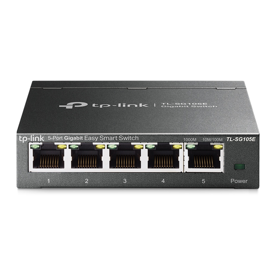
Introduction Appearance Description Appearance Description Front Panel The front panel of TL-SG105E is shown as the following figure. Figure 2-1 Front Panel of TL-SG105E The front panel of TL-SG108E is shown as the following figure. Figure 2-2 Front Panel of TL-SG108E The front panel of TL-SG116E is shown as the following figure.
-
Page 10: Rear Panel
Introduction Appearance Description 2.2 Rear Panel The rear panel of TL-SG105E is shown as the following figure. Figure 2-4 Rear Panel of TL-SG105E The rear panel of TL-SG108E is shown as the following figure. Figure 2-5 Rear Panel of TL-SG108E The rear panel of TL-SG116E is shown as the following figure.
-
Page 11: Logging Into The Switch
Introduction Logging Into the Switch Logging Into the Switch To configure your switch through a web browser on your PC, follow these steps: 1) Connect your switch to the network and connect your PC to the switch. 2) Find out the IP address of the switch. By default, the switch receives an IP address from a DHCP server (or a router that functions as a DHCP server) in your network.
-
Page 12
Introduction Logging Into the Switch Figure 3-2 Logging Into the Switch 7) The typical web interface displays below. You can view the running status of the switch and configure the switch on this interface. Figure 3-3 Launching the Web Interface User Guide… -
Page 13: Managing System
Part 2 Managing System CHAPTERS 1. System 2. Configuring System Info 3. Configuring IP 4. Configuring User Account 5. Backing up and Restoring the Switch 6. Rebooting the Switch 7. Reseting the Switch 8. Upgrading the Firmware 9. Appendix: Default Parameters…
-
Page 14: System
System Reset is used to reset the switch to the factory default setting. All the settings will be cleared after the switch is reset. Firmware Upgrade To upgrade the firmware is to get more functions and better performance. Go to the website to download the updated firmware. https://www.tp-link.com User Guide…
-
Page 15: Configuring System Info
Managing System Configuring System Info Configuring System Info With system information configuration, you can: View the system information Specify the device description 2.1 Viewing the System Information Choose the menu System > System Info to load the following page. You can view the basic system information of the switch.
-
Page 16: Configuring Ip
Managing System Configuring IP Configuring IP You can configure the system IP address in the following two ways: Configure the System IP Address Using DHCP Configure the System IP Address Manually Configuring the System IP Address Using DHCP Choose the menu System >…
-
Page 17
Managing System Configuring IP Subnet Mask Specify the subnet mask of the switch.. Default Gateway Specify the default gateway of the switch. 3) Click Apply. User Guide… -
Page 18: Configuring User Account
Managing System Configuring User Account Configuring User Account With user account management, you can modify the administrator’s username and password in order to refuse illegal users. Choose the menu System > User Account to load the following page. Figure 4-1 Configuring User Account Follow these steps to configure the user account: 1) Specify the new username, enter the old password, specify a new password and confirm the new password.
-
Page 19: Backing Up And Restoring The Switch
Managing System Backing up and Restoring the Switch Backing up and Restoring the Switch With backup and restore, you can: Save the current configuration. Restore to the previous configuration. 5.1 Saving the Current Configuration Choose the menu System > System Tools > Backup and Restore to load the following page.
-
Page 20: Restoring To The Previous Configuration
Managing System Backing up and Restoring the Switch 5.2 Restoring to the Previous Configuration Choose the menu System > System Tools > Backup and Restore to load the following page. Figure 5-2 Restoring the Configuration Follow these steps to restore the switch to the previous configuration: 1) In the Config Restore section, click Browse to load the following page.
-
Page 21
Managing System Backing up and Restoring the Switch 2) Click Open and the following page will be displayed. In the Config Restore section, click Restore Config to restore the switch to the previous configuration. It will take effect after the switch automatically reboots. Figure 5-4 Restoring to the Previous Configuration Note: It will take several minutes to restore the configuration. -
Page 22: Rebooting The Switch
Managing System Rebooting the Switch Rebooting the Switch Choose the menu System > System Tools > System Reboot to load the following page. Click Reboot. Figure 6-1 Rebooting the Switch Note: It will take several minutes to reboot the switch. Wait without any operation while the switch •…
-
Page 23: Reseting The Switch
Managing System Reseting the Switch Reseting the Switch Choose the menu System > System Tools > System Reset to load the following page. Figure 7-1 Reseting the Switch Follow these steps to reset the switch. 1) Click Reset, and the following page will pop up. Figure 7-2 Being Sure to Reset the Switch 2) Click OK to reset the switch.
-
Page 24: Upgrading The Firmware
Managing System Upgrading the Firmware Upgrading the Firmware For TL-SG105E and TL-SG108E Choose the menu System > System Tools > Firmware Upgrade to load the following page. Figure 8-1 Being Ready to Upgrade the Firmware Follow these steps to upgrade the firmware: 1) Click Ready to load the following page.
-
Page 25
Managing System Upgrading the Firmware 3) Click Browse to load the following page. Specify the firmware file path and select the firmware to upgrade. Figure 8-4 Browsing the Firmware File 4) Click Open. The following page will be displayed. Click Upgrade. Figure 8-5 Upgrading the Firmware User Guide… -
Page 26
Managing System Upgrading the Firmware Note: It will take several minutes to upgrade the firmware. Wait without any operation. • Select the proper software version matching with the hardware to upgrade. • To avoid damage, do not power down the switch while upgrading the firmware. •… -
Page 27
Managing System Upgrading the Firmware Follow these steps to upgrade the firmware: 1) Click Choose File to load the following page. Specify the firmware file path and select the firmware to upgrade. Figure 8-7 Browsing the Firmware File 2) Click Open and the following page will be displayed. Click Upgrade. Figure 8-8 Upgrading the Firmware User Guide… -
Page 28
Managing System Upgrading the Firmware Note: It will take several minutes to upgrade the firmware. Wait without any operation. • Select the proper software version matching with the hardware to upgrade. • To avoid damage, do not power down the switch while upgrading the firmware. •… -
Page 29: Appendix: Default Parameters
Managing System Appendix: Default Parameters Appendix: Default Parameters Default settings of System Info are listed in the following table. Table 9-1 Default Settings of System Info Parameter Default Setting Device Description The model name of the switch. Default settings of IP Setting are listed in the following table. Table 9-2 Default Settings of IP Address Configuration Parameter…
-
Page 30: Switching
Part 3 Switching CHAPTERS 1. Switching 2. Configuring Ports 3. Configuring IGMP Snooping 4. Configuring LAG 5. Configuration Examples 6. Appendix: Default Parameters…
-
Page 31: Switching
Switching Switching Switching 1.1 Overview With the switching feature, you can configure port setting, IGMP Snooping and LAG. 1.2 Supported Features The switch supports the following features about switching: Port Setting You can configure port status, speed, duplex mode and flow control for ports. IGMP Snooping In a point-to-multipoint network, packets can be sent in three ways: unicast, broadcast and multicast.
-
Page 32
Switching Switching a known multicast group will be transmitted to the designated receivers instead of being broadcast in the Layer2 network. The following figure shows how IGMP snooping works. Figure 1-1 IGMP Snooping Multicast packets transmission Multicast packets transmission with without IGMP Snooping IGMP Snooping Multicast router Multicast router… -
Page 33: Configuring Ports
Switching Configuring Ports Configuring Ports Choose the menu Switching > Port Setting to load the following page. Figure 2-1 Configuring Ports Follow these steps to configure the port parameters. 1) Select the desired ports and set basic parameters for the ports. Status Enable or disable the port.
-
Page 34
Switching Configuring Ports Note: It is recommended to set the ports on both ends of a link with the same speed and duplex • mode. Keep the port that is connected to the management device enabled, or you cannot access the •… -
Page 35: Configuring Igmp Snooping
Switching Configuring IGMP Snooping Configuring IGMP Snooping Choose the menu Switching > IGMP Snooping to load the following page. Figure 3-1 Configuring IGMP Snooping Follow these steps to configure IGMP Snooping. 1) Enable IGMP Snooping. Enable or disable report message suppression according to your needs.
-
Page 36: Configuring Lag
The max number of LAG groups that the switch can support is as follows: • 1 for TL-SG105E; 2 for TL-SG108E; 8 for TL-SG116E Each LAG group has 2 port members at least and 4 port members at most. •…
-
Page 37: Configuration Examples
Switching Configuration Examples Configuration Examples 5.1 Example for Configuring IGMP Snooping 5.1.1 Network Requirements Host B, Host C and Host D are in the same VLAN of the switch. All of them want to receive multicast streams sent to the same multicast group. As shown in the following topology, Host B, Host C and Host D are connected to port 1, port 2 and port 3 respectively.
-
Page 38: Configuration Steps
Switching Configuration Examples Demonstrated with TL-SG105E, the following section provides configuration steps. 5.1.3 Configuration Steps 1) Choose the menu VLAN > 802.1Q VLAN to load the following page. Select the 802.1Q VLAN Configuration as Enable. Click Apply. Specify the VLAN ID as 2. Specify the VLAN name as VLAN2.
-
Page 39: Example For Configuring Lag
Switch B Hosts Servers Demonstrated with TL-SG105E, the following section provides configuration steps. The configuration steps are similar for both switches, here we take Switch A for example. 5.2.2 Configuration Steps Choose the menu Switching > LAG to load the following page. Add Port 1, Port 2 and Port 3 to LAG 1.
-
Page 40: Appendix: Default Parameters
Switching Appendix: Default Parameters Appendix: Default Parameters Default settings of Port are listed in the following table. Table 6-1 Default Settings of Port Configuration Parameter Default Setting Status Enabled Speed/Duplex Auto Flow Control Default settings of IGMP Snooping are listed in the following table. Table 6-2 Default Settings of IGMP Snooping Configuration Parameter…
-
Page 41: Monitoring
Part 4 Monitoring CHAPTERS 1. Monitoring 2. Viewing Port Statistics 3. Configuring Port Mirror 4. Testing Cables 5. Configuring Loop Prevention 6. Appendix: Default Parameters…
-
Page 42: Monitoring
Monitoring Monitoring Monitoring 1.1 Overview With the monitoring feature, you can monitor the traffic on the switch. 1.2 Supported Features Port Statistics Port Statistics is used to display the information of each port, which facilitates you to monitor the traffic and locate faults promptly. Port Mirror Port Mirror is used to monitor network traffic by forwarding copies of incoming and outgoing packets from one or multiple ports (mirrored ports) to a specified port (mirroring…
-
Page 43: Viewing Port Statistics
Monitoring Viewing Port Statistics Viewing Port Statistics Choose the menu Monitoring > Port Statistics to load the following page. Figure 2-1 Viewing Port Statistics You can view the statistics of each port. You can click Clear to clear the data, also you can click Refresh to refresh the data.
-
Page 44: Configuring Port Mirror
Monitoring Configuring Port Mirror Configuring Port Mirror Choose the menu Monitoring > Port Mirror to load the following page. Figure 3-1 Configuring Port Mirror Follow these steps to configure port mirror: 1) Enable the port mirror feature globally. Specify a mirroring port. Click Apply. Port Mirror Enable or disable the port mirror feature globally.
-
Page 45
Monitoring Configuring Port Mirror Ingress For each port, select whether the ingress packets are mirrored. With this option enabled, the packets received by the port will be copied to the mirroring port. With this option disabled, the packets received by the port will not be copied to the mirroring port. -
Page 46: Testing Cables
Monitoring Testing Cables Testing Cables Choose the menu Monitoring > Cable Test to load the following page. Figure 4-1 Testing Cables Follow these steps to diagnose the cable: 1) Select your desired ports for test. Click Apply to test cables connected to the selected ports.
-
Page 47: Configuring Loop Prevention
Monitoring Configuring Loop Prevention Configuring Loop Prevention Choose the menu Monitoring > Loop Prevention to load the following page. Figure 5-1 Configuring Loop Prevention Follow these steps to configure loop prevention: 1) Enable or disable loop prevention. Loop Prevention Enable or disable the loop prevention feature globally. 2) Click Apply.
-
Page 48: Appendix: Default Parameters
Monitoring Appendix: Default Parameters Appendix: Default Parameters Default settings of Port Mirror are listed in the following table. Table 6-1 Default Settings of Port Mirrror Configuration Parameter Default Setting Port Mirror Disable Default settings of Loop Prevention are listed in the following table. Table 6-2 Default Settings of Loop Preventikon Configuration Parameter…
-
Page 49: Configuring Vlan
Part 5 Configuring VLAN CHAPTERS 1. Overview 2. Configuring MTU VLAN 3. Configuring Port Based VLAN 4. Configuring 802.1Q VLAN 5. Configuration Example for 802.1Q VLAN 6. Appendix: Default Parameters…
-
Page 50: Overview
Configuring VLAN Overview Overview VLAN (Virtual Local Area Network) is a network technique that solves broadcasting issues in local area networks. It is usually applied in the following occasions: To restrict broadcast domain: VLAN technique divides a big local area network into several VLANs, and all VLAN traffic remains within its VLAN.
-
Page 51
Configuring VLAN Overview switch will first insert a VLAN tag to the frame, using the PVID (Port VLAN ID) of the port as its VID, and then forward it as a tagged frame. Note: The switch works in one and only one VLAN mode at any time. When a specific VLAN mode is enabled, the other two VLAN modes will be disabled automatically and the corresponding VLAN configuration will be lost. -
Page 52: Configuring Mtu Vlan
Configuring VLAN Configuring MTU VLAN Configuring MTU VLAN Choose the menu VLAN > MTU VLAN to load the following page. Figure 2-1 Configuring MTU VLAN Follow these steps to configure MTU VLAN: 1) Select MTU VLAN configuration as Enable. Click Apply. MTU VLAN Enable or disable the MTU VLAN mode.
-
Page 53: Configuring Port Based Vlan
Configuring VLAN Configuring Port Based VLAN Configuring Port Based VLAN Choose the menu VLAN > Port Based VLAN to load the following page. Figure 3-1 Configuring Port Based VLAN Follow these step to configure port based VLAN: 1) Select the port based VLAN configuration as Enable. Click Apply. Port Based Enable or disable the port based VLAN mode.
-
Page 54: Configuring 802.1Q Vlan
Configuring VLAN Configuring 802.1Q VLAN Configuring 802.1Q VLAN To complete the 802.1Q configuration, follow these steps: 1) Configure the VLAN, including creating a VLAN and adding the ports to the VLAN. 2) Configure the PVID. 4.1 Configuring the VLAN Choose the menu VLAN > 802.1Q VLAN to load the following page. Figure 4-1 Configuring 802.1Q VLAN Follow these steps to configure the VLAN: 1) Select the 802.1Q VLAN Configuration as Enable.
-
Page 55: Configuring The Pvid
Configuring VLAN Configuring 802.1Q VLAN VLAN Name Enter a VLAN name for identification. The VLAN name should not be more than 10 characters using digits, letters, hyphens and underlines only. Untagged / Set the port as an untagged port, as a tagged port or not as a member port Tagged / Not in the VLAN.
-
Page 56
Configuring VLAN Configuring 802.1Q VLAN Note: The PVID configuration will takes effect only when 802.1Q VLAN mode is enabled. • You can specify a PVID only when the corresponding VLAN exists. • User Guide… -
Page 57: Configuration Example For 802.1Q Vlan
Configuring VLAN Configuration Example for 802.1Q VLAN Configuration Example for 802.1Q VLAN 5.1 Network Requirements Offices of Department A and Department B in the company are located in different places, and some computers in different offices are connected to the same switch. It is required that computers can communicate with each other in the same department but not with computers in the other department.
-
Page 58: Network Topology
Configuring VLAN Configuration Example for 802.1Q VLAN 5.3 Network Topology The figure below shows the network topology. Host A1 and Host A2 are in Department A, while Host B1 and Host B2 are in Department B. Switch A and Switch B are located in two different places.
-
Page 59: Configuration Steps
Configuration Example for 802.1Q VLAN 5.4 Configuration Steps Demonstrated with TL-SG105E, the following section provides configuration steps. The configuration steps on both switches are similar, here we take Switch A for example. 1) Choose the menu VLAN > 802.1Q VLAN to load the following page. Select 802.1Q VLAN configuration as Enable.
-
Page 60
Configuring VLAN Configuration Example for 802.1Q VLAN 2) Choose the menu VLAN > 802.1Q VLAN to load the following page. Specify the VLAN ID as 2, specify the VLAN name as Dept_A. Add port 2 to the VLAN as an untagged port. Add port 4 to the VLAN as a tagged port. -
Page 61
Configuring VLAN Configuration Example for 802.1Q VLAN 3) Choose the menu VLAN > 802.1Q VLAN to load the following page. Specify the VLAN ID as 3, specify the VLAN name as Dept_B. Add port 3 to the VLAN as an untagged port. Add port 4 to the VLAN as a tagged port. -
Page 62: Appendix: Default Parameters
Configuring VLAN Appendix: Default Parameters Appendix: Default Parameters Default settings of VLAN are listed in the following tables. Table 6-1 Default Settings of MTU VLAN Configuration Parameter Default Setting MTU VLAN Configuration Disable Table 6-2 Default Settings of Port Based VLAN Configuration Parameter Default Setting Port Based VLAN Configuration…
-
Page 63: Configuring Qos
Part 6 Configuring QoS CHAPTERS 1. QoS 2. Configuring Basic QoS 3. Configuring Bandwidth Control 4. Configuring Storm Control 5. Configuration Example for Basic QoS 6. Appendix: Default Parameters…
-
Page 64: Qos
Configuring QoS 1.1 Overview With network scale expanding and applications developing, internet traffic is dramatically increased, thus resulting in network congestion, packet drops and long transmission delay. Typically, networks treat all traffic equally on FIFO (First In First Out) delivery basis, but nowadays many special applications like VoD, video conferences, VoIP, etc.
-
Page 65: Configuring Basic Qos
Configuring QoS Configuring Basic QoS Configuring Basic QoS Configuration Guidelines Select the QoS mode according to your network requirements. Three QoS modes are supported on the switch: Port Based, 802.1P Based and DSCP Based. Port Based The port based QoS mode supports four priority queues, which are labeled as 1 (Lowest), 2 (Normal), 3 (Medium) and 4 (Highest).
-
Page 66: Configuring Qos In Port Based Mode
Configuring QoS Configuring Basic QoS 2.1 Configuring QoS in Port Based Mode Choose the menu QoS > QoS Basic to load the following page. Figure 2-1 Configuring Basic QoS in Port Based Mode Follow these steps to configure QoS in port based mode: 1) In the Global Config section, select QoS mode as Port Based.
-
Page 67: Configuring Qos In Dscp Based Mode
Configuring QoS Configuring Basic QoS Follow these steps to configure QoS in 802.1P based mode: 1) Select QoS mode as 802.1P Based. QoS Mode Select the QoS mode. 802.1P Based: In 802.1P based mode, the tagged packets are mapped to 4 priority levels based on the Pri value in 802.1Q tag (Lowest = 1, 2;…
-
Page 68: Configuring Bandwidth Control
Configuring QoS Configuring Bandwidth Control Configuring Bandwidth Control Choose the menu QoS > Bandwidth Control to load the following page. Figure 3-1 Configuring Bandwidth Control Follow these steps to configure bandwidth control: 1) Select the desired ports and configure the ingress rate and egress rate for the ports. Ingress Rate Configure the bandwidth for receiving packets on the port.
-
Page 69: Configuring Storm Control
Configuring QoS Configuring Storm Control Configuring Storm Control Choose the menu QoS > Storm Control to load the following page. Figure 4-1 Configuring Storm Control Follow these steps to configure storm control: 1) Select the desired ports and configure the upper rate limit for forwarding broadcast packets, multicast packets and UL-frames (Unknown unicast frames).
-
Page 70
Configuring QoS Configuring Storm Control Note: For a port, the storm control feature and the ingress rate control feature cannot be enabled at • the same time. If you enable storm control for a port, ingress rate control will be disabled for that port automatically. -
Page 71: Configuration Example For Basic Qos
RD department. Follow these procedures to configure QoS in port based mode. 1) Enable port based mode. 2) Map port 1 and port 2 to different priorities queues. Demonstrated with TL-SG105E, the following section provides configuration steps. User Guide…
-
Page 72: Configuration Steps
Configuring QoS Configuration Example for Basic QoS 5.3 Configuration Steps 1) Choose the menu QoS > QoS Basic to load the following page. In the Global Config section, select QoS mode as Port Based. Click Apply. Figure 5-2 Configuring Basic QoS in Port Based Mode 2) In the Port Based Priority Setting section, specify the priority queue for port 1 as 1(Lowest) and click Apply.
-
Page 73: Appendix: Default Parameters
Configuring QoS Appendix: Default Parameters Appendix: Default Parameters Default settings of QoS basic configuration are listed in the following table. Table 6-1 Default Settings of QoS Basic Configuration Parameter Default Setting QoS Mode DSCP/802.1P Based Priority Queue 1 (Lowest) Default settings of Bandwidth Control configuration are listed in the following table. Table 6-2 Default Settings of Bandwidth Control Configuration Parameter…
-
Page 74
No part of the specifications may be reproduced in any form or by any means or used to make any derivative such as translation, transformation, or adaptation without permission from TP-Link Technologies Co., Ltd. Copyright © 2018 TP-Link Technologies Co., Ltd. All rights reserved. http://www.tp-link.com… -
Page 75
We, TP-Link USA Corporation, has determined that the equipment shown as above has been shown to comply with the applicable technical standards, FCC part 15. There is no unauthorized change is made in the equipment and the equipment is properly maintained and operated. -
Page 76
We, TP-Link USA Corporation, has determined that the equipment shown as above has been shown to comply with the applicable technical standards, FCC part 15. There is no unauthorized change is made in the equipment and the equipment is properly maintained and operated. -
Page 77
EU declaration of conformity TP-Link hereby declares that the device is in compliance with the essential requirements and other relevant provisions of directives 2014/53/EU, 2009/125/EC and 2011/65/EU. The original EU declaration of conformity may be found at http://www.tp-link.com/en/ce Industry Canada Statement (For TL-SG105E/TL-SG108E) -
Page 78
Продукт сертифіковано згідно с правилами системи УкрСЕПРО на відповідність вимогам нормативних документів та вимогам, що передбачені чинними законодавчими актами України. Safety Information Keep the device away from water, fire, humidity or hot environments. Do not attempt to disassemble, repair, or modify the device. Do not use damaged charger or USB cable to charge the device. -
Page 79
RECYCLING This product bears the selective sorting symbol for Waste electrical and electronic equipment (WEEE). This means that this product must be handled pursuant to European directive 2012/19/EU in order to be recycled or dismantled to minimize its impact on the environment. User has the choice to give his product to a competent recycling organization or to the retailer when he buys a new electrical or electronic equipment.
-
Contents
-
Table of Contents
-
Bookmarks
Quick Links
User Guide
TL-SG105
TL-SG108
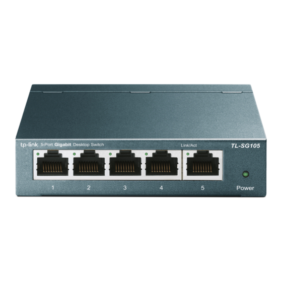
5/8-Port Gigabit Desktop Switch
REV1.0.1
7106504303
Related Manuals for TP-Link TL-SG105
Summary of Contents for TP-Link TL-SG105
-
Page 1: User Guide
User Guide TL-SG105 TL-SG108 5/8-Port Gigabit Desktop Switch REV1.0.1 7106504303…
-
Page 3: Copyright And Trademarks
COPYRIGHT & TRADEMARKS Specifications are subject to change without notice. is a registered trademark of TP-LINK TECHNOLOGIES CO., LTD. Other brands and product names are trademarks or registered trademarks of their respective holders. No part of the specifications may be reproduced in any form or by any means or used to make any derivative such as translation, transformation, or adaptation without permission from TP-LINK TECHNOLOGIES CO.,…
-
Page 4: Fcc Statement
FCC STATEMENT This equipment has been tested and found to comply with the limits for a Class B digital device, pursuant to part 15 of the FCC Rules. These limits are designed to provide reasonable protection against harmful interference in a residential installation. This equipment generates, uses and can radiate radio frequency energy and, if not installed and used in accordance with the instructions, may cause harmful interference to radio communications.
-
Page 5: Ce Mark Warning
Any changes or modifications not expressly approved by the party responsible for compliance could void the user’s authority to operate the equipment. CE Mark Warning This is a class B product. In a domestic environment, this product may cause radio interference, in which case the user may be required to take adequate measures.
-
Page 6: Package Contents
TL-SG105/TL-SG108 5/8-port Gigabit Desktop Switch without any explanation. Note: The two devices of TL-SG105 and TL-SG108 are sharing this User Guide. For simplicity, we will take TL-SG108 for example throughout this Guide. The differences between TL-SG105 and TL-SG108 are shown as following: …
-
Page 7: Chapter 1 Introduction Of The Product
The TL-SG105/TL-SG108 switch is plug-and-play. In addition, the Auto- MDI/MDIX cable detection on all ports eliminates the demand of crossover cable or Uplink port. Each port can be used as general ports or Uplink ports, and any port can be simply plugged into a server, a hub, a router, a switch or a PC, using the straight cable or crossover cable.
-
Page 8: Features
Supports QoS (802.1p/Q-based) function 4K entry MAC address table of TL-SG105/TL-SG108 with auto- learning and auto-aging Supports for Jumbo frames of up to 9KB LED indicators for monitoring power, link, speed and activity …
-
Page 9: Chapter 2 Identifying External Components
Chapter 2 Identifying External Components This chapter describes the front panel and rear panel of the switch. 2.1 Front Panel Figure 2-1 TL-SG108 Switch Front Panel The following parts are located on the front panel: Ports (1-8): The TL-SG108 switch is equipped with 8 10/100/ 1000Mbps Auto-Sensing RJ45 ports where you will connect your network devices.
-
Page 10: Rear Panel Overview
2.2 Rear Panel Figure 2-2 TL-SG108 Switch Rear Panel The following parts are located on the rear panel: Kensington Security Slot: The switch provides one security slot. Power socket: The power socket, located at the right side of the rear panel, is where you will connect the power adapter.
-
Page 11: Mounting The Switch On A Wall
To ensure the stable cable connection, please keep the switch horizontal on the desktop, with white cover facing up. 3.2 Mounting the Switch on a Wall There are two wall-mounting slots on the bottom panel of the switch. To mount the switch on a wall, please follow the steps below. Drill two holes into the wall.
-
Page 12: Status Indication
3.3 Power On Power on the switch and it will automatically initialize and its LED indicators will respond as follows: Name Time Status Indication Power All the time Power on second second LEDs device connected (port 1-8) corresponding port. second~ There is a 10/100/1000Mbps device connected to the corresponding port.
-
Page 13: Appendix A: Specifications
Network Media(Cable) UTP category 5, 5e cable (maximum 100m) EIA/TIA-568 100Ω STP (maximum 100m) 1000Base-T: UTP category 5 cable (maximum 100m) EIA/TIA-568 100Ω STP (maximum 100m) 5 10/100/1000Mbps Auto-Negotiation RJ45 ports (TL-SG105) Number of Ports 8 10/100/1000Mbps Auto-Negotiation RJ45 ports (TL-SG108)
-
Page 14
LED indicators Power, LEDs Transfer Method Store-and-Forward automatically learning, automatically aging MAC Address Learning 10Base-T: 14880pps/Port Frame Filter Rate 100Base-Tx: 148800pps/Port 1000Base-T: 1488000pps/Port 10Base-T: 14880pps/Port Frame Forward Rate 100Base-Tx: 148800pps/Port 1000Base-T: 1488000pps/Port Environmental and Physical Operating Temperature 0 ~40 (32 ~104 ) ℃… -
Page 15: Appendix B: Troubleshooting
Appendix B: Troubleshooting 1. The Power LED is not lit Check to see if the AC power cord is connected to the switch properly, and make sure the power source is ON. 2. The Link/Act LED is not lit when a device is connected to the corresponding port Check to see if the cable connectors are firmly plugged into the switch and the device, and verify the connected device is turned on…
This manual is also suitable for:
Tl-sg108
![]()
User Guide
Easy Smart Switch
1910012769 REV5.1.0
May 2020
|
CONTENTS |
|
|
About This Guide |
|
|
Intended Readers…………………………………………………………………………………………………………………………………………….. |
1 |
|
Conventions……………………………………………………………………………………………………………………………………………………… |
1 |
|
More Information……………………………………………………………………………………………………………………………………………… |
2 |
|
Introduction |
|
|
Product Overview…………………………………………………………………………………………………………………………………………….. |
4 |
|
Logging Into the Switch………………………………………………………………………………………………………………………………….. |
5 |
|
Managing System |
|
|
System……………………………………………………………………………………………………………………………………………………………….. |
8 |
|
Overview…………………………………………………………………………………………………………………………………………………………………………………. |
8 |
|
Supported Features……………………………………………………………………………………………………………………………………………………………. |
8 |
|
Configuring System Info…………………………………………………………………………………………………………………………………. |
9 |
|
Viewing the System Information…………………………………………………………………………………………………………………………………….. |
9 |
|
Specifying the Device Description………………………………………………………………………………………………………………………………… |
9 |
|
Configuring IP………………………………………………………………………………………………………………………………………………… |
10 |
|
Configuring LED (Only for Certain Devices)……………………………………………………………………………………………… |
12 |
|
Configuring User Account…………………………………………………………………………………………………………………………… |
13 |
|
Backing up and Restoring the Switch………………………………………………………………………………………………………… |
14 |
|
Saving the Current Configuration……………………………………………………………………………………………………………………………….. |
14 |
|
Restoring to the Previous Configuration………………………………………………………………………………………………………………….. |
15 |
|
Rebooting the Switch……………………………………………………………………………………………………………………………………. |
17 |
|
Resetting the Switch…………………………………………………………………………………………………………………………………….. |
18 |
|
Upgrading the Firmware………………………………………………………………………………………………………………………………. |
19 |
|
Appendix: Default Parameters……………………………………………………………………………………………………………………. |
21 |
|
Switching |
|
|
Switching………………………………………………………………………………………………………………………………………………………… |
23 |
|
Overview………………………………………………………………………………………………………………………………………………………………………………. |
23 |
|
Supported Features…………………………………………………………………………………………………………………………………………………………. |
23 |
|
Configuring Ports………………………………………………………………………………………………………………………………………….. |
25 |
|
Configuring IGMP Snooping………………………………………………………………………………………………………………………… |
27 |
|
Configuring LAG…………………………………………………………………………………………………………………………………………….. |
28 |
|
Configuration Examples……………………………………………………………………………………………………………………………….. |
30 |
|
Example for Configuring IGMP Snooping…………………………………………………………………………………………………………………. |
30 |
|
Network Requirements……………………………………………………………………………………………………………………………………….. |
30 |
|
Configuration Scheme……………………………………………………………………………………………………………………………………….. |
30 |
|
Configuration Steps…………………………………………………………………………………………………………………………………………….. |
31 |
|
Example for Configuring LAG……………………………………………………………………………………………………………………………………….. |
32 |
|
Network Requirements……………………………………………………………………………………………………………………………………….. |
32 |
|
Configuration Steps…………………………………………………………………………………………………………………………………………….. |
33 |
|
Appendix: Default Parameters……………………………………………………………………………………………………………………. |
34 |
|
Monitoring |
|
|
Monitoring………………………………………………………………………………………………………………………………………………………. |
36 |
|
Overview………………………………………………………………………………………………………………………………………………………………………………. |
36 |
|
Supported Features…………………………………………………………………………………………………………………………………………………………. |
36 |
|
Viewing Port Statistics…………………………………………………………………………………………………………………………………. |
37 |
|
Configuring Port Mirror………………………………………………………………………………………………………………………………… |
39 |
|
Testing Cables……………………………………………………………………………………………………………………………………………….. |
41 |
|
Configuring Loop Prevention………………………………………………………………………………………………………………………. |
43 |
|
Appendix: Default Parameters……………………………………………………………………………………………………………………. |
44 |
|
Configuring VLAN |
|
|
Overview…………………………………………………………………………………………………………………………………………………………. |
46 |
|
Configuring MTU VLAN………………………………………………………………………………………………………………………………… |
48 |
|
Configuring Port Based VLAN…………………………………………………………………………………………………………………….. |
49 |
|
Configuring 802.1Q VLAN……………………………………………………………………………………………………………………………. |
50 |
|
Configuring the VLAN……………………………………………………………………………………………………………………………………………………… |
50 |
|
Configuring the PVID……………………………………………………………………………………………………………………………………………………….. |
52 |
|
Configuration Example for 802.1Q VLAN………………………………………………………………………………………………….. |
53 |
|
Network Requirements…………………………………………………………………………………………………………………………………………………… |
53 |
|
Configuration Scheme……………………………………………………………………………………………………………………………………………………. |
53 |
|
Configuration Steps…………………………………………………………………………………………………………………………………………………………. |
55 |
|
Appendix: Default Parameters……………………………………………………………………………………………………………………. |
59 |
|
Configuring QoS |
|
|
QoS………………………………………………………………………………………………………………………………………………………………….. |
61 |
|
Overview………………………………………………………………………………………………………………………………………………………………………………. |
61 |
|
Supported Features…………………………………………………………………………………………………………………………………………………………. |
61 |
|
Configuring Basic QoS ………………………………………………………………………………………………………………………………… |
62 |
|
Configuring QoS in Port Based Mode……………………………………………………………………………………………………………………….. |
63 |
|
Configuring QoS in 802.1P Based Mode………………………………………………………………………………………………………………….. |
64 |
|
Configuring QoS in DSCP/802.1P Based Mode…………………………………………………………………………………………………….. |
64 |
|
Configuring Bandwidth Control…………………………………………………………………………………………………………………… |
65 |
|
Configuring Storm Control………………………………………………………………………………………………………………………….. |
67 |
|
Configuration Example for Basic QoS……………………………………………………………………………………………………….. |
69 |
|
Network Requirements…………………………………………………………………………………………………………………………………………………… |
69 |
|
Configuration Scheme……………………………………………………………………………………………………………………………………………………. |
69 |
|
Configuration Steps…………………………………………………………………………………………………………………………………………………………. |
70 |
|
Appendix: Default Parameters……………………………………………………………………………………………………………………. |
72 |
|
Configuring PoE (Only for Certain Devices) |
|
|
Overview…………………………………………………………………………………………………………………………………………………………. |
74 |
|
Configuring PoE…………………………………………………………………………………………………………………………………………….. |
75 |
|
Configuring PoE Auto Recovery…………………………………………………………………………………………………………………. |
77 |
|
Appendix: Default Parameters……………………………………………………………………………………………………………………. |
79 |
About This Guide |
Intended Readers |
About This Guide
This Configuration Guide provides information for configuring the Easy Smart Switch via the web interface. Read this guide carefully before operation.
You can also configure the switch using the Easy Smart Configuration Utility. For more information, refer to the Easy Smart Configuration Utility User Guide. Go to the website https://www.tp-link.com/support, search the model number of your switch, and you can find this guide on the product Support web page.
Intended Readers
This Guide is intended for network managers familiar with IT concepts and network terminologies.
Conventions
When using this guide, notice that features available in Easy Smart Switch may vary by model and software version. The availability of Easy Smart Switch may also vary by region or ISP. All images, steps, and descriptions in this guide are only examples and may not reflect your actual experience. Throughout the guide, we will take TL-SG1016PE as the switch to be configured for example.
Some models featured in this guide may be unavailable in your country or region. For local sales information, visit https://www.tp-link.com.
The information in this document is subject to change without notice. Every effort has been made in the preparation of this document to ensure accuracy of the contents, but all statements, information and recommendations in this document do not constitute the warranty of any kind, express or implied. Users must take full responsibility for their application of any products.
In this Guide, the following conventions are used:
PoE budget calculations are based on laboratory testing. Actual PoE power budget is not guaranteed and will vary as a result of client limitations and environmental factors.
The symbol  stands for Note. Notes contain suggestions or references that help you make better use of your device.
Menu Name > Submenu Name > Tab page indicates the menu structure. SYSTEM > System Info > System Summary means the System Summary page under the System Info menu option that is located under the SYSTEM menu.
Bold font indicates a button, toolbar icon, menu or menu item.
User Guide 
 1
1
|
About This Guide |
More Information |
More Information
■■ The latest software and documentations can be found at Download Center at https://www.tp-link.com/support.
■■ The Installation Guide (IG) can be found where you find this guide or inside the package of the switch.
■■ The authentication information can be found where you find this guide.
■■ Specifications can be found on the product page at https://www.tp-link.com.
■■ To ask questions, find answers, and communicate with TP-Link users or engineers, please visit https://community.tp-link.com to join TP-Link Community.
■■ Our Technical Support contact information can be found at the Contact Technical Support page at https://www.tp-link.com/support.
User Guide 
 2
2
Part 1
Introduction
CHAPTERS
1.Product Overview
2.Logging Into the Switch

|
Introduction |
Product Overview |
1Product Overview
Easy Smart Switch is an ideal upgrade from Unmanaged Switch, designed for Small Office and Home Office networks. The switch supports the following features:
■■ Traffic monitoring: Port mirroring, loop prevention and cable test enable the administrator to monitor traffic of the network effectively.
■■ VLAN: MTU VLAN, Port based VLAN and 802.1Q VLAN can restrict broadcast domain, enhance network security and help manage devices easily.
■■ QoS: Port based QoS, 802.1P based QoS and DSCP/802.1P based QoS optimize traffic on your business network, and keep latency-sensitive traffic moving smoothly. Bandwidth control helps distribute and utilize network bandwidth reasonably. Storm control helps avoid network broadcast storm.
■■ PoE: PoE (Power over Ethernet) is a remote power supply function. With this function, the switch can supply power to the connected devices over twisted-pair cables.
Note:
●● The PoE feature is only available on certain devices. To check whether your device supports this feature, refer to the datasheet.
●● PoE configuration is only available on certain devices. To check whether your device supports this feature, refer to the actual web interface.
User Guide  4
4

|
Introduction |
Logging Into the Switch |
2Logging Into the Switch
To configure your switch through a web browser on your PC, follow these steps:
1)Connect your switch to the network and connect your PC to the switch.
2)Find out the IP address of the switch.
■■ By default, the switch receives an IP address from a DHCP server (or a router that functions as a DHCP server) in your network. You can find out this IP address on the DHCP server.
■■ If the switch cannot receive an IP address from a DHCP server, it uses the static IP address of 192.168.0.1, with a subnet mask of 255.255.255.0.
3)Configure IP address on your PC to make sure the switch and PC are in the same subnet.
■■ If the switch uses an IP address assigned by a DHCP server, set your PC to obtain an IP address automatically from the DHCP server.
■■ If the switch uses the static IP address of 192.168.0.1, configure your PC’s IP address as 192.168.0.x (”x” ranges from 2 to 254), and subnet mask as
255.255.255.0.
4)Launch a web browser on your PC. The supported web browsers include, but are not limited to, the following types:
■■ IE 8.0, 9.0, 10.0, 11.0 ■■ Firefox 26.0, 27.0
■■ Chrome 32.0, 33.0
5)In the address bar of the web browser, enter the IP address of the switch. Here we suppose the switch uses the static IP address 192.168.0.1.
Figure 2-1 Entering the IP Address of the Switch in the Browser
User Guide 
 5
5

|
Introduction |
Logging Into the Switch |
6)Enter the username and password in the pop-up login window. Enter admin for both username and password in lower case letters.
Figure 2-2 Logging Into the Switch
Note:
The first time you log in, change the password to better protect your network and devices.
7)The typical web interface displays below. You can view the running status of the switch and configure the switch on this interface.
Figure 2-3 Launching the Web Interface
User Guide 
 6
6
Part 2
Managing System
CHAPTERS
1.System
2.Configuring System Info
3.Configuring IP
4.Configuring LED (Only for Certain Devices)
5.Configuring User Account
6.Backing up and Restoring the Switch
7.Rebooting the Switch
8.Resetting the Switch
9.Upgrading the Firmware
10.Appendix: Default Parameters
1System
1.1Overview
In System module, you can view the system information and configure the system parameters and features of the switch.
1.2Supported Features
System Info
The System Info is mainly used to view the system information and configure the device description.
IP Setting
Each device in the network possesses a unique IP address. You can access the switch using IP address of the switch. You can set IP address of the switch manually or using DHCP.
User Account Management
User Account Management is mainly used to modify the administrator’s username and password in order to refuse illegal users.
Backup and Restore
Backup and Restore is used to download the current configuration and save it as a file to your computer, and upload a backup configuration file to restore your switch to the previous configuration.
System Reboot
System Reboot is used to reboot the switch.
System Reset
System Reset is used to reset the switch to the factory default setting. All the settings will be cleared after the switch is reset.
Firmware Upgrade
To upgrade the firmware is to get more functions and better performance. Go to the website https://www.tp-link.com to download the updated firmware.
User Guide 
 8
8

|
Managing System |
Configuring System Info |
2Configuring System Info
With system information configuration, you can: ■■ View the system information
■■ Specify the device description
2.1Viewing the System Information
Choose the menu System > System Info to load the following page. You can view the basic system information of the switch.
Figure 2-1 Viewing the System Summary
2.2Specifying the Device Description
Choose the menu System > System Info to load the following page. Specify a new device description for the switch, and click Apply.
Figure 2-2 Specifying the Device Description
User Guide 
 9
9
|
Managing System |
Configuring IP |
3Configuring IP
You can configure the system IP address in the following two ways: ■■ Configure the System IP Address Using DHCP
■■ Configure the System IP Address Manually
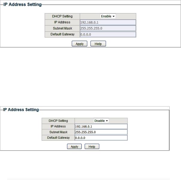
Configuring the System IP Address Using DHCP
Choose the menu System > IP Setting to load the following page.
Figure 3-1 Configuring System IP Address Using DHCP
Follow these steps to configure the system IP address using DHCP:
1)Select DHCP setting as Enable from the drop-down list .
2)Click Apply. The switch will obtain IP settings from the DHCP server.
Configuring the System IP Address Manually
Choose the menu System > IP Setting to load the following page.
Figure 3-2 Configuring System IP Address Manually
Follow these steps to configure the system IP address manually:
1)Select DHCP setting as Disable from the drop-down list.
2)Specify the IP address, subnet mask and default gateway.
|
IP Address |
Specify the system IP of the switch. You can use this IP address to access |
|
the switch. |
User Guide  10
10

|
Managing System |
Configuring IP |
|
Subnet Mask |
Specify the subnet mask of the switch.. |
|
Default Gateway |
Specify the default gateway of the switch. |
3) Click Apply.
User Guide 
 11
11
Managing System Configuring LED (Only for Certain Devices)
4Configuring LED (Only for Certain Devices)
Note:
LED configuration is only available on certain devices. To check whether your device supports this feature, refer to the actual web interface.
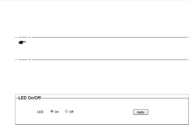
With this function, you can turn on or turn off the LED with one click.
Choose the menu System > LED On/Off to load the following page. Choose the LED status and click Apply.
Figure 4-1 Configuring LED On/Off
User Guide 
 12
12
|
Managing System |
Configuring User Account |
5Configuring User Account
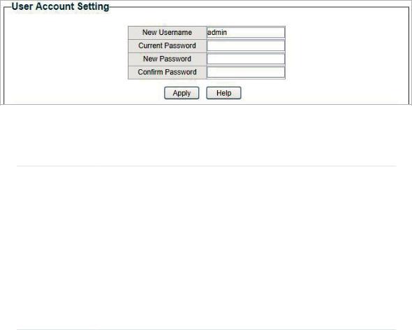
With user account management, you can modify the administrator’s username and password in order to refuse illegal users.
Choose the menu System > User Account to load the following page.
Figure 5-1 Configuring User Account
Follow these steps to configure the user account:
1)Specify the new username, enter the current password, specify a new password and confirm the new password.
|
New Username |
Create a user name for login. Requirement for the user name varies among |
|
different devices. If your user name fails to meet the requirement, check |
|
|
the prompt information. |
|
|
Current |
Enter the current password of the switch. By default, the password is |
|
Password |
admin. |
|
New Password |
Specify a new password for login. Requirement for the password varies |
|
among different devices. If your password fails to meet the requirement, |
|
|
check the prompt information. |
|
|
Confirm |
Retype the new password. |
|
Password |
2) Click Apply.
User Guide 
 13
13
|
Managing System |
Backing up and Restoring the Switch |
6Backing up and Restoring the Switch
With backup and restore, you can: ■■ Save the current configuration.
■■ Restore to the previous configuration.
6.1Saving the Current Configuration
Choose the menu System > System Tools > Backup and Restore to load the following page. In the Config Backup section, click Backup Config to save the configuration file to your PC.
Figure 6-1 Backing Up the Configuration
Note:
It will take several minutes to save the configuration file. Wait without any operation.
User Guide 
 14
14
|
Managing System |
Backing up and Restoring the Switch |
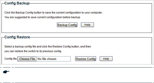
6.2Restoring to the Previous Configuration
Choose the menu System > System Tools > Backup and Restore to load the following page.
Figure 6-2 Restoring the Configuration
Follow these steps to restore the switch to the previous configuration:
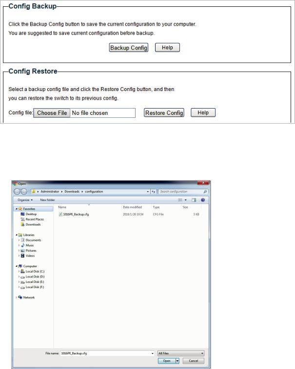
1)In the Config Restore section, click Choose File to load the following page. Specify the configuration file path and select the configuration file.
Figure 6-3 Choosing the Configuration File
User Guide 
 15
15
|
Managing System |
Backing up and Restoring the Switch |
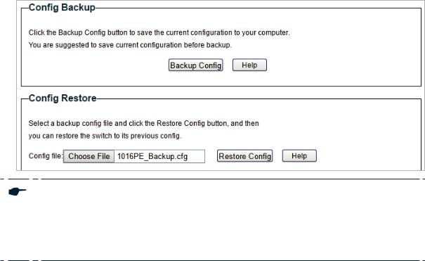
2)Click Open and the following page will be displayed. In the Config Restore section, click Restore Config to restore the switch to the previous configuration. It will take effect after the switch automatically reboots.
Figure 6-4 Restoring to the Previous Configuration
Note:
●● It will take several minutes to restore the configuration. Wait without any operation. ●● To avoid any damage, do not power down the switch while being restored.
●● After being restored, the current configuration of the switch will be lost.
User Guide 
 16
16
![]()
|
Managing System |
Rebooting the Switch |
7Rebooting the Switch
Choose the menu System > System Tools > System Reboot to load the following page. Click Reboot.
Figure 7-1 Rebooting the Switch
Note:
●● It will take several minutes to reboot the switch. Wait without any operation while the switch reboots.
●● To avoid any damage, do not power down the switch while the switch reboots.
User Guide  17
17
|
Managing System |
Resetting the Switch |
8Resetting the Switch
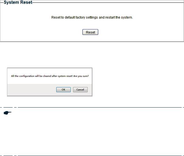
Choose the menu System > System Tools > System Reset to load the following page.
Figure 8-1 Resetting the Switch
Follow these steps to reset the switch.
1) Click Reset, and the following page will pop up.
Figure 8-2 Being Sure to Reset the Switch
2) Click OK to reset the switch.
Note:
●● After the switch is reset, it will reboot automatically.
●● It will take several minutes to reboot the switch. Wait without any operation while the switch reboots.
●● To avoid any damage, do not power down the switch during the reset. ●● After the switch is reset, all the settings will be restored to the default.
User Guide  18
18
|
Managing System |
Upgrading the Firmware |
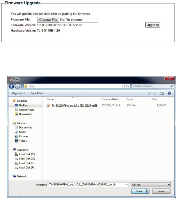
9Upgrading the Firmware
Choose the menu System > System Tools > Firmware Upgrade to load the following page.
Figure 9-1 Being Ready to Upgrade the Firmware
Follow these steps to upgrade the firmware:
1)Click Choose File to load the following page. Specify the firmware file path and select the firmware to upgrade.
Figure 9-2 Browsing the Firmware File
User Guide 
 19
19
|
Managing System |
Upgrading the Firmware |
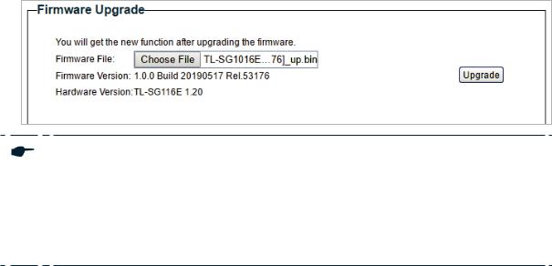
2) Click Open and the following page will be displayed. Click Upgrade.
Figure 9-3 Upgrading the Firmware
Note:
●● It will take several minutes to upgrade the firmware. Wait without any operation. ●● Select the proper software version matching with the hardware to upgrade.
●● To avoid damage, do not power down the switch while upgrading the firmware. ●● It is recommended to backup the configuration before upgrading.
User Guide 
 20
20

|
Managing System |
Appendix: Default Parameters |
10Appendix: Default Parameters
Default settings of System Info are listed in the following table.
Table 10-1 Default Settings of System Info
|
Parameter |
Default Setting |
|
Device Description |
The model name |
|
of the switch. |
Default settings of IP Setting are listed in the following table.
Table 10-2 Default Settings of IP Address Configuration
|
Parameter |
Default Setting |
|
DHCP Setting |
Enable |
|
IP Address |
192.168.0.1 |
|
Subnet Mask |
255.255.255.0 |
|
Default Gateway |
0.0.0.0 |
Default settings of User Account are listed in the following table.
Table 10-3 Default Settings of User Account Configuration
|
Parameter |
Default Setting |
|
New Username |
admin |
User Guide 
 21
21
Part 3
Switching
CHAPTERS
1.Switching
2.Configuring Ports
3.Configuring IGMP Snooping
4.Configuring LAG
5.Configuration Examples
6.Appendix: Default Parameters
 Loading…
Руководство по установке
Гигабитный коммутатор Easy Smart PoE+
Светодиод Пояснение
Питания
На: Включение питания
Мигает: Ненормальная работа или сброс
Off: Выключить
Ссылка/Действие; Восходящий1, Восходящий2
Зеленый горит:
Скорость 1000 Мбит / с, но нет активности.
Зеленый мигает:
Работает на скорости 1000 Мбит / с и передает или принимает данные.
Желтый горит:
Работает со скоростью 10/100 Мбит / с, но без активности.
Желтый мигающий:
Работает со скоростью 10/100 Мбит / с и передает или принимает данные.
Off:
К соответствующему порту не подключено ни одно устройство.
Статус PoE
На: Обеспечение питания PoE
Мигает: Ошибка PoE
Off: Не обеспечивает питание PoE
PoE МАКС.
Для TL-SG105PE:
На: 58 Вт ≤ Общая мощность < 65 Вт
Мигает: Общая мощность ≥ 65 Вт
Off: Общая мощность < 58 Вт
Для TL-SG105MPE:
На: 113 Вт ≤ Общая мощность < 120 Вт
Мигает: Общая мощность ≥ 120 Вт
Off: Общая мощность < 113 Вт
Для TL-SG108PE:
На: 57 Вт ≤ Общая мощность < 64 Вт
Мигает: Общая мощность ≥ 64 Вт
Off: Общая мощность < 57 Вт
Для TL-SG1210MPE:
На: 116 Вт ≤Общая мощность < 123 Вт
Мигает: Общая мощность ≥ 123 Вт
Off: Общая мощность < 116 Вт
Примечание: Для простоты возьмем для примера TL-SG108PE.ample в этом Руководстве.
Подключения

Конфигурация
Переключатель подключи и работай. Для настройки коммутатора вы можете использовать Webна основе графического интерфейса пользователя или утилиты настройки.
Утилита сейчас поддерживается только в Windows.
Посмотрите на график Web-на основе графического интерфейса
- Узнайте IP-адрес коммутатора.
По умолчанию коммутатор получает IP-адрес от DHCP-сервера (обычно это маршрутизатор с включенной функцией DHCP) в вашей сети. Узнать этот IP-адрес можно на DHCP-сервере.
Если коммутатор не может получить IP-адрес от DHCP-сервера, он использует статический IP-адрес 192.168.0.1 с маской подсети 255.255.255.0. - Настройте IP-адрес на своем ПК, чтобы коммутатор и ПК находились в одной подсети.
Если коммутатор использует IP-адрес, назначенный DHCP-сервером, настройте компьютер на автоматическое получение IP-адреса от DHCP-сервера.
Если коммутатор использует 192.168.0.1 в качестве IP-адреса, настройте IP-адрес вашего ПК как 192.168.0.x («x» находится в диапазоне от 2 до 254), а маску подсети — как 255.255.255.0. - Запустить web браузера на вашем ПК, введите IP-адрес коммутатора в адресной строке и нажмите Enter. Войдите в систему с администратором как имя пользователя, так и пароль.
Теперь вы можете настроить коммутатор с помощью Webна основе графического интерфейса. Для получения дополнительной информации см. Руководство пользователя.
Перейдите на https://www.tp-link.com/support, выполните поиск по номеру модели вашего коммутатора, и вы сможете найти это руководство в разделе поддержки продукта. web стр.
Примечание:
- Для некоторых устройств вам может потребоваться изменить пароль при первом входе в систему, чтобы лучше защитить вашу сеть и устройства.
- Если коммутатор получит новый IP-адрес от DHCP-сервера, ваше соединение с коммутатором будет потеряно. Введите новый IP-адрес в браузере, чтобы снова получить доступ к коммутатору.
Использование утилиты настройки
- Перейдите на https://www.tp-link.com/support и найдите номер модели вашего коммутатора. Загрузите утилиту Easy Smart Configuration Utility из службы поддержки продукта. web страницу на вашем ПК.
- Распакуйте загруженный file, запустите мастер установки и следуйте инструкциям по установке утилиты Easy Smart Configuration.
- Дважды щелкните значок
 на рабочем столе, а Домашняя страница утилиты отобразит список переключателей TP-Link в локальной сети.
- Нажмите
 узнать IP параметры коммутатора.
– Если коммутатор использует IP-адрес, назначенный DHCP-сервером, настройте ПК на автоматическое получение IP-адреса от DHCP-сервера.
– Если коммутатор использует 192.168.0.1 в качестве IP-адреса, настройте IP-адрес вашего ПК как 192.168.0.x («x» находится в диапазоне от 2 до 254) и маску подсети как 255.255.255.0. - Дважды щелкните переключатель, который вы хотите настроить. Войдите в систему с администратором как имя пользователя, так и пароль.
Теперь вы можете настроить коммутатор с помощью утилиты настройки. Для получения дополнительной информации см. Руководство пользователя Easy Smart Configuration Utility.
Перейдите на https://www.tp-link.com/support, выполните поиск по номеру модели вашего коммутатора, и вы сможете найти это руководство в разделе поддержки продукта. web стр.
Характеристики
Общие характеристики
| Стандарт | IEEE802.3i, IEEE802.3u, IEEE802.3ab, IEEE802.3af, IEEE 802.3at, IEEE802.3x, IEEE802.1p, IEEE802.1q Для TL-SG1210MPE: IEEE802.3z |
| Интерфейс | Для TL-SG105PE/TL-SG105MPE/TL-SG108PE: 5/8 портов 10/100/1000 Мбит / с RJ45 автосогласование, автоматический MDI/MDIX; Порты PoE: порт 1– порт 4 Для TL-SG1210MPE: 10 портов 10/100/1000 Мбит/с RJ45 автосогласование, автоматический MDI/MDIX; 1 порт SFP 1000 Мбит / с (комбинированный); Порты PoE: порт 1-порт 8 |
| Скорость передачи данных | Ethernet: 10 Мбит/с (полудуплекс), 20 Мбит/с (полный дуплекс) Fast Ethernet: 100 Мбит/с (полудуплекс), 200 Мбит/с (полный дуплекс) Gigabit Ethernet: 2000 Мбит / с (полный дуплекс) |
| Сетевые СМИ (Кабель) | 10Base-T: кабель UTP категорий 3, 4, 5 (максимум 100 м) EIA / TIA-568 100 Ом STP (максимум 100 м) 100Base-TX: кабель UTP категории 5, 5e (максимум 100 м) EIA / TIA-568 100 Ом STP (максимум 100 м) 100BASE-FX/LX10/BX10: MMF, SMF (только для TL-SG1210MPE) 1000Base-T: кабель UTP категории 5e или выше (максимум 100 м) EIA/TIA-568 100 Ом STP (максимум 100 м) 1000BASE-SX / LX / LX10 / BX10: MMF, SMF (только для TL-SG1210MPE) |
| Напряжение питания | Внешний адаптер питания Вход: 100-240 В переменного тока, 50/60 Гц Выход: 53.5 В постоянного тока / 2.43 А (для TL-SG1210MPE) 53.5 В постоянного тока / 1.31 А (для TL-SG105PE / TL-SG108PE) 53.5 В постоянного тока/2.43 А (для TL-SG105MPE) |
| Бюджет PoE | TL-SG105PE: 65 Вт TL-SG105MPE: 120 Вт TL-SG108PE: 64 Вт TL-SG1210MPE: 123 Вт |
| Коммутационная способность | TL-SG105PE/TL-SG105MPE: 10 Гбит/с TL-SG108PE: 16 Гбит / с TL-SG1210MPE: 20 Гбит / с |
| Таблица MAC-адресов | TL-SG105PE / TL-SG105MPE: 2K, автоматическое обучение, автоматическое старение TL-SG108PE / TL-SG1210MPE: 4K, автоматическое обучение, автоматическое старение |
| Возможность крепления к стене | Да |
| Расстояние между монтажными отверстиями | TL-SG105PE/TL-SG105MPE: 39 мм TL-SG108PE: 94 мм TL-SG1210MPE: 150 мм |
Часто задаваемые вопросы (FAQ)
Q1. Почему не горит индикатор питания?
– Индикатор питания должен гореть, когда система питания работает нормально. Если индикатор питания не горит, попробуйте следующее:
– A1: Убедитесь, что адаптер питания правильно подключен к коммутатору с источником питания.
– A2: Убедитесь, что громкостьtage блока питания соответствует требованиям входного напряженияtagе переключателя.
– A3: Убедитесь, что источник питания включен.
– A4: На странице конфигурации включения/выключения светодиодов проверьте, горит ли состояние светодиода. По умолчанию светодиодный индикатор включен.
Q2. Почему светодиод Link / Act не горит, когда устройство подключено к соответствующему порту?
– Пожалуйста, попробуйте следующее:
– A1: Убедитесь, что кабельные разъемы надежно подключены к коммутатору и устройству.
– A2: Убедитесь, что подключенное устройство включено и работает нормально.
– A3: длина кабеля не должна превышать 100 метров (328 футов). Если включен режим расширения, оно должно быть менее 250 метров (820 футов).
– A4: На странице конфигурации включения/выключения светодиодов проверьте, горит ли состояние светодиода. По умолчанию светодиодный индикатор включен.
Q3. Почему порт PoE / PoE + не обеспечивает питание устройств PoE?
– Когда общее энергопотребление подключенных устройств PoE превышает максимальное значение, порт PoE с меньшим номером порта имеет более высокий приоритет. Система отключит питание портов с большим номером порта, чтобы обеспечить подачу питания на другие порты. Взять TL-SG108PE как бывшийampле. Порты 1, 2 и 4 потребляют 15.4 Вт соответственно. Если к порту 18 подключить дополнительное устройство PoE мощностью 3 Вт, система отключит питание порта 4, чтобы компенсировать перегрузку.
Условия окружающей среды и физические характеристики
| Сертификация | FCC, CE, RoHS |
| Рабочая Температура | От 0 ˚C до 40 ˚C (от 32 ˚F до 104 ˚F) |
| Температура хранения | От -40 ˚C до 70 ˚C (от -40 ˚F до 158 ˚F) |
| Влажность при эксплуатации | От 10% до 90% без конденсации |
| Влажность хранения | От 5% до 90% без конденсации |
![]() Чтобы задать вопросы, найти ответы и пообщаться с пользователями или инженерами TP-Link, посетите https://community.tp-link.com присоединиться к сообществу TP-Link.
Чтобы задать вопросы, найти ответы и пообщаться с пользователями или инженерами TP-Link, посетите https://community.tp-link.com присоединиться к сообществу TP-Link.![]() Для получения технической поддержки и другой информации посетите https://www.tp-link.com/supportили просто отсканируйте QR-код.
Для получения технической поддержки и другой информации посетите https://www.tp-link.com/supportили просто отсканируйте QR-код.

http://www.tp-link.com/support
![]() Декларация соответствия ЕС
Декларация соответствия ЕС
TP-Link настоящим заявляет, что устройство соответствует основным требованиям и другим соответствующим положениям директив 2014/30 / EU, 2014/35 / EU, 2009/125 / EC, 2011/65 / EU и (EU) 2015 / 863.
Оригинал декларации соответствия ЕС можно найти на https://www.tp-link.com/en/support/ce/
Декларация соответствия Великобритании
TP-Link настоящим заявляет, что устройство соответствует основным требованиям и другим соответствующим положениям Правил электромагнитной совместимости 2016 г. и Правил безопасности электрического оборудования 2016 г.
Оригинал декларации о соответствии для Великобритании можно найти по адресу https://www.tp-link.com/support/ukca/
Информация по технике безопасности
- Держите устройство подальше от воды, огня, влажности или жарких сред.
- Не пытайтесь разбирать, ремонтировать или модифицировать устройство. Если вам нужна услуга, свяжитесь с нами.
- Положите устройство нижней стороной вниз.
- Не используйте поврежденное зарядное устройство или USB-кабель для зарядки устройства.
- Не используйте другие зарядные устройства, кроме рекомендованных.
- Адаптер должен быть установлен рядом с оборудованием и должен быть легко доступен.
- Вилка шнура питания используется как устройство отключения, розетка должна быть легко доступна.