-
Page 1
Patient Monitor MPR6-03 User Manual RM 501.01.000-01-01 UM Version 7, 05/2020… -
Page 3: Table Of Contents
CONTENT 1. DEVICE DESCRIPTION ……………………….6 1.1. I …………………………6 NTRODUCTION 1.1.1. Intended Use …………………………. 6 1.1.2. Basics of Operation and Construction ………………….7 1.1.3. General …………………………. 9 1.1.4. Revision History ……………………….10 1.1.5. Symbols and Marks ……………………… 11 1.1.6. General Specifications ……………………..14 1.2.
-
Page 4
2.2.5. Analysis of Heart Rate Variability (HRV) ………………..91 2.2.6. Synthesis of ECG Leads ……………………..92 2.2.7. Features of the Operation with a Pacemaker (PM) ……………… 92 2.2.8. Features of the Operation in the Operating Rooms ……………… 93 2.2.9. Disinfection of the Patient Cable ………………….93 2.2.10. -
Page 5
3.10.1. Basic Principles of cNIBP Method ………………….. 162 3.10.2. dPWTT Measurement and NIBP Trigger Conditions …………….163 3.10.3. Continuous Arterial Blood Pressure Calculation …………….. 165 3.10.4. Operation of cNIBP Mode ……………………166 3.10.5. Limitations of cNIBP Method ………………….. 167 3.11. MAINSTREAM CO SENSOR …………………… -
Page 6: Device Description
1. Device Description 1.1. Introduction 1.1.1. Intended Use The present operating manual applies to the portable bedside monitor MPR6-03- «Triton» (here- inafter referred to as the device). The device is designed for long-term and continuous monitoring of the following patient parame-…
-
Page 7: Basics Of Operation And Construction
1.1 Introduction to monitor vital functions during operations, in the postoperative period, during inva- sive diagnostic interventions and intensive care; to work in extreme conditions of disaster medicine; for screening. 1.1.2. Basics of Operation and Construction The operation of the pulse oximetry module is based on different spectral absorption of oxy- hemoglobin and reduced blood hemoglobin.
-
Page 8
1.1 Introduction Computer network support allows the device to operate as part of a centralized monitoring com- puter network (CMS), view on a computer and save in its memory the data recorded by the de- vice. The built-in thermal printer provides a printout of the parameters recorded by the device (in- stalled by special order). -
Page 9: General
1.1 Introduction 1.1.3. General The present operating manual is an integral part of the device and is included in its delivery kit. The present document is provided for informational purposes only, it is not allowed to copy, re- produce, translate into another language, save in an information retrieval system, transmit in any form or convert it into a form suitable for storage on electronic media without written per- mission manufacturer Before starting to work with the device, carefully read the present User Manual.
-
Page 10: Revision History
1.1 Introduction To ensure the operability of the device and increase its service life during operation, it is NEC- ESSARY: protect the device from dropping and knocking, especially on the surface of the liquid crystal display; do not allow pressing the touch buttons on the device display with hard objects with sharp corners to avoid damage to the touch panel;…
-
Page 11: Symbols And Marks
1.1 Introduction 1.1.5. Symbols and Marks Symbols, icons and marks used on the device housing Russian Conformity mark Type approval mark (measurement means according legislation of the Russian Fed- eration) ATTENTION, refer to the operating documents! Refer to the operating documents! Serial number Manufacturing date IP21…
-
Page 12
1.1 Introduction Infoport “Infoports” for mainstream CO CAPNO sensor, depth of anesthesia module Ethernet Connector to a local computer network Port for USB Flash memory devices POWER Device power supply LED Charger and internal battery warning LED OPEN Built-in thermal printer cover latch POWER Power supply LED for built-in thermal printer ERROR… -
Page 13
1.1 Introduction Reset to the factory settings Start NIBP measurement Stop NIBP measurement Trends in a graphical form Trends in a table form Curve fragments window Switch the trend scale (figure — current scale) Button for moving along the trends or selecting the serial number of the recorded frag- ment of the curves at the review Button for moving page-by page Start / cancel printing on a thermal printer (in the tabular trend window and in the wave-… -
Page 14: General Specifications
1.1 Introduction 1.1.6. General Specifications Parameter Description General Multiparameter patient monitor for the Intended use long-term and continuous monitoring of the vital functions of the patient. Operation modes (patient groups) Adult, pediatric, neonatal 220 ± 22 V / 50 Hz AC power Operation from a fully charged built-in battery At least 120 min…
-
Page 15
1.1 Introduction Continuous non-invasive blood pressure measurement available (cNIBP)– SysAD, DiaAD, MapAD, PWTT Monitoring of central hemodynamics parameters by the available volume compression oscillometry: non-invasive meas- urement of cardiac output (CO), stroke volume (SV), sys- temic vascular resistance (SVR) with the calculation of a number of related parameters 2.6 Temperature (T), skin and central, 2 channels available… -
Page 16
1.1 Introduction 3.15 Detection range of QRS-complex amplitude 0.05 — 10 mV Pulse oximetry channel Displaying of pulse rate, perfusion, SpO Digital Displaying of the photoplethysmogram Continious Scaling of the photoplethysmogram Automatic indication range 10 — 100 % measurement range 70 — 100 % ±2 % Absolute accuracy of SpО… -
Page 17
1.1 Introduction Non-invasive monitoring of cardiac output (channel of the central hemodynamics) Measurement method — volumetric compression oscil- Available lometry Measured parameters: — SV – stroke volume 10 — 250 ml — СО – cardiac output 1.0 — 20 lpm Calculated parameters: — CI –… -
Page 18
1.1 Introduction ART (Arterial blood pressure), PA (Pulmonary artery pressure), CVP (Central venous pressure), Types (markers) of the measured pressure: ICP (Intracranial pressure) 10.5 RAP (Right atrial pressure), LAP (Left atrial pressure) RVP (Right ventricular pressure) UA (Umbilical arterial pressure) 10.6 Invasive pressure measurement range: -50…… -
Page 19
1.1 Introduction Measurement range: — СО 13.3 concentration 0 — 15 % — СО partial pressure 0 — 115 mmHg Measurement accuracy of СО concentration: ±0.2 % — absolute in the range 0 — 5 % ±4 % — relative in the range 5,1 — 10 % ±6 % — relative in the range 10,1 — 15 % 13.4… -
Page 20
1.1 Introduction Displayed graphic parameters: EEG curve in one measured lead with adjustment of Available the window size (5, 10, 30, 60 s) and EEG scale (10 — 1000 mV) Trends of brain activity index and EMG level with ad- Available 15.3 justable trend length (5, 10, 30, 60 min) -
Page 21
1.1 Introduction 19.4 Temporarily disable the audible alarm for 2 min Available 19.5 System of text messages to the user about alarm Available HR/PR, SpO , SysAD, DiaAD, MapAD, ЧД, Т, StDev. 19.6 Setting of alarm limits for parameters EtCO , FiCO , EtO , FiO… -
Page 22: Getting Started
1.2 Getting Started 1.2. GETTING STARTED 1.2.1. Appearance and Controls Figure 1-1. Appearance of the Patient Monitor MPR6-03 Front panel Screen (color TFT-display) with the touch control panel. The «BATTERY» indicator informs about the operation of the charger and the internal rechargeable battery: off — battery is charged;…
-
Page 23
11 — Manipulator (encoder) to control the device. 12 — Lamp «ALARM» for additional attention, blinks red when an alarm is triggered. Figure 1-2. Patient Monitor MPR6-03, front view The surface of the liquid crystal display of the device shall be protected from shock and other mechanical influences to avoid unevenness, scratch- es, as well as damage to the touch panel and display. -
Page 24
10 — sensor. 11 — Pneumatic connector for the respiratory mechanics module. 12 — Connector for microflow line for sampling. Figure 1-4. Patient Monitor MPR6-03, side view (panel of ports and connectors) Bacterial filter Clips for attaching to the connector panel… -
Page 25: Operating Conditions
“POWER” LED — indicates power supply. Paper exit slot. Cover of the built-in thermal printer. Figure 1-6. Patient Monitor MPR6-03, side view (the built-in thermal printer cover) 1.2.2. Operating Conditions Ambient temperature 10…35 °С. Note. The operating time from the built-in battery is standardized for charging and discharging at tem- peratures from +20 ºС…
-
Page 26: Safety Instructions
1.2 Getting Started 1.2.3. Safety Instructions For safety device meets the requirements of GOST R 50444, GOST R IEC 60601-1, GOST R IEC 60601-1-6, GOST IEC 60601-1-8, GOST R IEC 62304, GOST R IEC 62366, GOST 31515.1, GOST 31515.3, GOST 30324.30, GOST R IEC 60601-2-27, GOST R IEC 60601-2-49, GOST R 50267.34, GOST ISO 9919, GOST ISO 10993-1, GOST R ISO 80601-2-55, GOST R ISO 15223-1, GOST Р…
-
Page 27
1.2 Getting Started fixing equipment and accessories outside the center of gravity. when placing the trolley-mounted device on an inclined plane, the swivel wheels with a brake must be at the bottom to prevent the device from slipping; be careful when transporting the device on the trolley; to prevent overturning when moving, hold the trolley handle with both hands. -
Page 28: Preparing To Turn On The Device
1.2 Getting Started 1.2.4. Preparing to Turn on the Device The device is intended only for visual display and automatic registration of the basic vital physiological parameters of the patient and cannot relieve medical personnel from the obligation of continuous physical observation of the patient.
-
Page 29: Disinfection
1.2 Getting Started Do not try to switch on the device immediately after switch it off. The delay between switching off the device and its subsequent switching on must be at least 5 seconds. During this time pressing the » «…
-
Page 30: Device Control
1.3 Device Control 1.3. DEVICE CONTROL The device is controlled by the touch screen, control buttons “F”, “123”, “CAPNO”, “NIBP”, “FREEZE”, « » and the encoder. 1.3.1. Display (Screen Configuration) Cardiometry window. You can set here display mode (one or three ECG curves) and numerical pa- rameters of the arrhythmia analysis.
-
Page 31: Touch Panel
1.3 Device Control 1.3.2. Touch Panel The device is controlled using the touch screen. Press the screen to change the operation mode of the output window or to change the parameter. A more detailed description of the control of the device using the touch screen is described in the following sections. 1.3.3.
-
Page 32: Configuring Of Curves On The Screen
1.3 Device Control 1.3.5. Configuring of Curves on the Screen To change the measurement channel, press on the name of the curve: You will see at the screen the list of available channels (depending on options in the device): Select the channel you want to display by pressing: Histgrm heart rate variability window PPG SpO (pulse oximetry) window…
-
Page 33: Setting Of Date And Time
1.3 Device Control 1.3.6. Setting of Date and Time Click on the date and time field: You will see the window for setting the date and time: Select the required field for correction by clicking on it, it will be highlighted in a different color. Use the buttons to set the required value.
-
Page 34: Setting Of Sound Alarm Volume
1.3 Device Control 1.3.7. Setting of Sound Alarm Volume Click on the sound control icon: The volume setting window will be displayed: Select the required field for correction by clicking on it, it will be highlighted in a different color. Use buttons to set the required value.
-
Page 35: Setting Of General Parameters, Modes Of Gas Analysis And Displaying Of Hr/ Pr And Rr
1.3 Device Control 1.3.8. Setting of General Parameters, Modes of Gas Analysis and Displaying of HR/ PR and RR When FREEZE mode is activated, it is not possible to enter the general pa- rameters menu. To select the display mode for HR / PR, RR and enter the menu for setting of general parame- ters, click on the corresponding icons on the device screen: HR or PR source selection…
-
Page 36
1.3 Device Control Setting of parameters in accordance with it.1.3.10. Click on the field with the corresponding parameter, select it and set the required value (digital parameters in accordance with p. 1.3.10). The appearance of the general parameters window may change depending on the set of options in the device. -
Page 37: Setting Of Profile
1.3 Device Control 1.3.9. Setting of Profile The device has several groups of profiles (i.e. options for setting parameters by module) stored in non-volatile memory. Profiles define: for the NIBP module — the limit value of the pressure generated in the cuff and the limit time for pressure measurement;…
-
Page 38
1.3 Device Control For all profiles it is possible to set the patient’s weight with an accuracy of 0.1 kg, the minimum value of the patient’s weight is 0.4 kg To restore the factory settings of the profile, click the corresponding icon: If the profile parameters were changed during operation by the user and differ from the factory settings, the display will show the window for returning to factory settings: If you press the «Yes»… -
Page 39
1.3 Device Control Profiles Unit Adult Pediatric Neonatal Bottom threshold RR 1/min Top threshold RR 1/min Bottom threshold Т ºC Top threshold Т ºC Bottom threshold segment Top threshold ST- segment Maximum cuff pressure mmHg Bottom threshold EtСО mmHg Top threshold EtСО mmHg Bottom threshold FiСО… -
Page 40: Setting Of Digital Parameters And Alarm Thresholds
1.3 Device Control 1.3.10. Setting of Digital Parameters and Alarm Thresholds Setting the values of digital parameters and alarm thresholds in the device is performed in the same way. To set the alarm thresholds of all displayed digital parameter, click on the displayed value of the top (or bottom) threshold of the corresponding parameter: You will see the window for setting the alarm threshold (for example, the window for setting the top alarm threshold by the Et value of the multigas module):…
-
Page 41
1.3 Device Control Turn the encoder knob in the required direction. To confirm the changed parameters, press the «OK» button (or the encoder button), to discard changes — «Cancel» Ranges for the alarm thresholds: Setting Symbol Parameter Step Range 350…13 Top threshold of HR/PR, 1/min Bottom threshold of HR/PR, 1/min 12…349… -
Page 42
1.3 Device Control Setting Symbol Parameter Step Range Top threshold of expiratory gas concentration 0.5…10.0 EtAх* Bottom threshold of expiratory gas concentra- 0.1…10.0 tion Top threshold of inspiratory gas concentration 0.5…10.0 FiAх* Bottom threshold of inspiratory gas concentra- 0.1…10.0 tion Top threshold of systolic BP for the channel 1 (2), mmHg 0 … -
Page 43: Setting Of Ecg-Channel Parameters
1.3 Device Control 1.3.11. Setting of ECG-channel Parameters The parameters of the ECG module are controlled using fields and icons located in the cardi- ometry window: To change a parameter, click on the field of its current value and select the required new value in the appeared window.
-
Page 44
1.3 Device Control After switching on the ECG synthesis mode S12, leads V1 — V6 become available for selection to display. S12 lead synthesis mode is available only when using a 5-electrode ECG cable. To control the generation of messages about the heart rhythm deviations, click on the arrhyth- mias list icon. -
Page 45: Setting Of Respiratory Parameters Module
1.3 Device Control 1.3.12. Setting of Respiratory Parameters Module To set the sweep speed of the respiratory parameters module and the required apnea interval, click on the corresponding field of the values of these parameters located in the respirogram window: Press on the required sweep speed and set the apnea interval in accordance with p.1.3.10.
-
Page 46: Settings Of Pulse Oxymetry Module
1.3 Device Control 1.3.13. Settings of Pulse Oxymetry Module Control of the parameters of the pulse oximetry module (the sweep speed and averaging time of digital parameters) is carried out using the fields and icons in ECG module window: To change a parameter, click on the display field of its current value and select the required new value in the window that appears after clicking.
-
Page 47: Settings Of Nibp Module
1.3 Device Control 1.3.14. Settings of NIBP Module Set the units of BP measurement, the measurement period of the NIBP module and select au- tomatic or manual modes of blood pressure measurement by clicking on the corresponding fields in the window of the NIBP channel: Changing of the units of Setting of the BP measure- measurement mmHg / kPa…
-
Page 48: Settings Of The Thermometry Module
1.3 Device Control 1.3.15. Settings of the Thermometry Module In the thermometry channel you can switch the measurement mode on T2 channel to the tem- perature difference measurement mode T1-T2. To switch the mode, click on the mode name in the thermometry channel window: After switching on the T1-T2 mode, the value of the temperature difference between the chan- nels T1 and T2 will be displayed on the T2 display channel:…
-
Page 49: Settings Of The Capnometry Module
1.3 Device Control 1.3.16. Settings of the Capnometry Module The parameters of the capnometry channel are controlled using the fields and icons in the cap- nogram window: Capnometer Setting the apnea zero setting interval and compensation of the O according it. 1.3.10) To change a parameter, click on the display field of its current value and select the required new value in the window that appears after clicking.
-
Page 50: Settings Of Multigas Module
1.3 Device Control 1.3.17. Settings of Multigas Module The parameters of the gas analysis module are controlled using fields and icons in the window of the graphical curves of the multigas channel: Set gas parameters in the field of corresponding gas: To change a parameter, click on the display field of its current value and select the required new value in the window that appears after clicking.
-
Page 51: Settings Of The Ibp Module
1.3 Device Control 1.3.18. Settings of the IBP Module The parameters of the invasive blood pressure measurement (IBP) module are controlled using fields and icons located in the IBP graphic window: To change a parameter, click on the display field of its current value and select the required new value in the window that appears after clicking.
-
Page 52: System Reset
1.3 Device Control 1.3.19. System Reset To make system reset press the button “ ” before turning the device on. Do not release it until the graphs appear on the screen. The screen view and all the device parameters will take their default values.
-
Page 53: Alarms
1.4 Alarms 1.4. ALARMS 1.4.1. Alarm System The alarms generated by the device can be: caused by the patient’s condition (the patient’s parameters measured by the device go out the set thresholds); caused by incorrect operator actions when monitoring a parameter or malfunctions of the device (technical alarms).
-
Page 54: Alarm Messages
1.4 Alarms The sound signal of a technical malfunction can be silenced by pressing the » » button until the next technical malfunction appears. The volume of the technical fault signal can be set in the window for setting the volume of sound signals (see p.
-
Page 55: Silencing The Audible Alarm
1.4 Alarms 1.4.3. Silencing the Audible Alarm The device has the following options to disable the sound alarm: Immediate temporary silencing — press the alarm off symbol on the touch screen (Fig. 1-8, position 19) or the » » button on the front panel of the device. Flashing symbol appears on the screen and all sound alarms turns off for 2 minutes, after which it is automatically re- stored (preschedule unlocking can be done by pressing the same button again),…
-
Page 56: Alarms Of The Pulse Oximetry Module
1.4 Alarms 1.4.4. Alarms of the Pulse Oximetry Module Message Alarm situation Sound alarm Light alarm (output window) « — — — » instead Low (weak) strength of the pulse Weak signal Three short of SрО beeps every 5 s (general) Flashing SрО…
-
Page 57
1.4 Alarms Message Alarm situation Sound alarm Light alarm (output window) sensor failure Sensor failure! Two-tone every 5 (PPG) Technical alarms are highlighted with gray fill. * – this alarm is triggered if the device has previously recorded readings via the pulse oximetry channel. -
Page 58: Alarms Of The Ecg And Respiratory Parameters Modules
1.4 Alarms 1.4.5. Alarms of the ECG and Respiratory Parameters Modules Message Alarm situation (output Sound alarm Light alarm window) « — — — » instead of HR No cardiac activity Asystole Continuous signal (general) Low ECG voltage Low ECG volt- age (general) HR value is less than bottom thresh- Flashing HR value…
-
Page 59: Alarms Of Nibp Module
1.4 Alarms 1.4.6. Alarms of NIBP Module Message (output Alarm situation Sound alarm Light alarm window) SYS value is less than bottom threshold < Flashing SYS value SYS value is less than bottom threshold Two short The same on a on 8…16 % beeps every 5 yellow back-…
-
Page 60
1.4 Alarms Message (output Alarm situation Sound alarm Light alarm window) MAP value is more than top threshold < 4 Flashing MAP value MAP value is more than top threshold on Two short The same on a 4…8 % beeps every yellow back- 10 s ground… -
Page 61: Alarms Of The Thermometry Module
1.4 Alarms Message (output Alarm situation Sound alarm Light alarm window) « — — — » instead Malfunction of the measuring circuit of the Pressure channel Two-tone every NIBP channel failure (NIBP) of BP « — — — » instead Independent NIBP alarm system triggered NIBP module failure! Two-tone every…
-
Page 62: Alarms Of The Capnometry Module
1.4 Alarms 1.4.8. Alarms of the Capnometry Module Message (output Alarm situation Sound alarm Light alarm window) Flashing EtCО EtCО value is less than bottom threshold < 5 value EtCО value is less than bottom threshold on Two short The same on a 5…10 % beeps every 5 yellow back-…
-
Page 63
1.4 Alarms Message (output Alarm situation Sound alarm Light alarm window) There were 3 unsuccessful attempts to purge Off: Occlusion Two-tone every the path (capno) Failed to dry the measuring chamber after 10 Off: Purging Fail Two-tone every (capno) Failure of the measuring chamber emitter Off: Emitter Fail Two-tone every (capno) -
Page 64: Alarms Of The Multigas Module
1.4 Alarms 1.4.9. Alarms of the Multigas Module Message (output Alarm situation Sound alarm Light alarm window) EtXXX value is less than bottom threshold Flashing EtXXX < 5 % value EtXXX value is less than bottom threshold Two short beeps The same on a on 5…10 % every 5 s…
-
Page 65
1.4 Alarms Message (output Alarm situation Sound alarm Light alarm window) Turned off manually by the «CAPNO» button Off by user (multi- or No breath signal at the multigas input gas) more than 1 hour Technical alarms are highlighted with gray fill. XXX –… -
Page 66: Alarms Of The Ibp Module
1.4 Alarms 1.4.10. Alarms of the IBP Module Message (output Alarm situation Sound alarm Light alarm window) SYS value is less than bottom threshold Flashing SYS < 8 % value of IBP1 (IBP2) channel SYS value is less than bottom threshold Two short beeps The same on a on 8…16 %…
-
Page 67: Measurement Of Parameters
2.1 SpO Monitoring 2. MEASUREMENT OF PARAMETERS 2.1. MONITORING OF ARTERIAL OXYGEN SATURATION (SpO Below in it. 2.1.1 — 2.1.3 there is a description if procedure for monitoring SpO using the «Triton» pulse oximetry module (TESM.505008). It. 2.1.4 describes the procedure for monitoring SpO using the Masimo SET pulse oximetry module, which can be optionally installed in the device.
-
Page 68: Application Of Finger Spo Sensors
2.1 SpO Monitoring 2.1.1. Application of Finger SpO Sensors Figure 2-1. Finger sensors (“clip” and rubber) Use a finger on a hand that does not have a pressure cuff or an arterial catheter. Choose a finger with a good pulse strength and the most appropriate sensor in size (if nail is polish, remove the polish before installing the sensor).
-
Page 69
2.1 SpO Monitoring Figure 2-3. Use of the neonatal sensor for newborns When installing a disposable neonatal sensor b) (Fig. 2-2 b, Fig. 2-3), it is necessary to locate the windows of the sensor’s photocells opposite each other. In the case of using the sensor of variant a) in older children or adult patients, the sensor can be located on the finger with fixation by the sensor strap (Fig. -
Page 70: Window Of The Pulse Oxymetry Channel
2.1 SpO Monitoring 2.1.3. Window of the Pulse Oxymetry Channel Display the photoplethysmogram curve in one of the configurable graphical curves display windows (section 1.3.5): filling column; photoplethysmogram (PPG); control icon for SpO sound alarm; top threshold of SpO bottom threshold of SpO measured value of SpO control symbol of HR/PR source.
-
Page 71
2.1 SpO Monitoring Depending on the patient’s mobility, set the most appropriate averaging time (the time after which the measured SрО value is determined): 4, 8 or 16 s (the default value is 16 s, which is most suitable for restless patients) (p. 1.3. 8). Patient movement can distort the sensor signal. -
Page 72: Spo Monitoring Using Masimo Set Technology
2.1 SpO Monitoring ® 2.1.4. SpO Monitoring using Masimo SET technology Description This section provides information on how to operate a device equipped with a pulse oximetry module using Masimo SET® technology (MS-2040) to monitor: saturation of arterial blood with oxygen, SpO photoplethysmogram, PPG heart rate obtained from photoplethysmogram, PR perfusion (filling) index — the numerical value of the pulsating component of the regis-…
-
Page 73
2.1 SpO Monitoring Grounding. Connect the device only to a three-wire, grounded, hospital-grade receptacle. The three-conductor plug must be inserted into a properly wired three-wire receptacle; if a three-wire receptacle is not available, a qualified electrician must install one in accordance with the governing electrical code. -
Page 74
2.1 SpO Monitoring The «Sensitivity» parameter is adjusted in the same way and has 3 values: «Max» (Maximum), «Norm» (Normal), «APOD» (Adaptive Probe Off Detection — adaptive detection of the absence of a sensor). The «Norm» sensitivity mode provides the best combination of sensitivity and sensor discon- nection detection. -
Page 75
2.1 SpO Monitoring (exposure to excessive illumination can be corrected by covering the sensor with a dark or opaque material) Excessive patient movement. Venous pulsations may cause erroneous low readings (e.g. tricuspid value regurgitation). Patient suffers from abnormal pulse rhythm. … -
Page 76
2.1 SpO Monitoring LNSC: DC-IP, YI, Adtx, Pdtx, Inf, NeoPt For sensors LNOP TC-I, Blue, LNCS TC-I, TF-I the error is not standardized 2 % measurement error (at low per- 4, 5 fusion) LNOP: DC-I, DC-IP, Adt, Pdt, Neo L (adult, ped.), Inf-L, LNSC: DC-IP, Adtx, Pdtx, Inf, Neo (adult, ped.), TF-I 3 % LNOP: Neo L (neonatal), NeoPt-L, Blue… -
Page 77
2.1 SpO Monitoring Sensors LNOP Blue Inf, LNOP TF-I, TC-I and LNCS TF-I, TC-I are not used for measurements in the presence of movement. Sensor LNOP YI is not used for measurements at low perfusion. SENSORS Use only Masimo oximetry sensors for SpO2 measurements. … -
Page 78
2.1 SpO Monitoring Sensor Description Application site Weight range 1864 LNCS DC-IP Pediatric reusable finger sensor Finger 10 — 50 kg 1895 LNCS TC-I Reusable ear sensor Ear lobe > 30 kg Foot 1- 3 kg * 2258 LNCS YI Reusable multi-site sensor Great toe >… -
Page 79
2.1 SpO Monitoring Alarm situation Message Sound alarm Light alarm Two short beeps The same on a SрО value is more than top threshold by every 5 s yellow back- 2…4 % ground Three short beeps The same on a SрО… -
Page 80
2.1 SpO Monitoring eliminate sources of interference, high illumination Low Signal IQ The quality of the signal does not allow to obtain reliable measurements Masimo SET End User License Agreement The present agreement is made between the End User (hereinafter referred to as the Purchaser) of the equipment and the Equipment Manufacturer Triton Electronic Systems Ltd. -
Page 81
2.1 SpO Monitoring formance, display or disclosure of the Software (including the related documentation) by the U.S. Gov- ernment or any of its agencies shall be governed solely by the terms of this Agreement and shall be pro- hibited except to the extent expressly permitted by the terms of this Agreement. -
Page 82: Disinfection Of Spo Sensors
2.1 SpO Monitoring 2.1.5. Disinfection of SpO Sensors Disinfection of sensors is carried out in accordance with the requirements of MU-287-113 by wiping them with a 3% solution of hydrogen peroxide with the addition of 0.5% neutral detergent of the «Lotos» type (it is allowed to use other disinfectants of different manufacturers, taking into account their methodology applications).
-
Page 83: Ecg Monitoring
2.2 ECG Monitoring 2.2. ECG MONITORING This icon indicates that the device and patient cable are specially pro- tected against electric shock and defibrillator shock (type CF). To connect the cable connector to the device, grasp the connector housing and firmly insert it into the corresponding connector of the device until it stops.
-
Page 84
2.2 ECG Monitoring Figure 2-9. ECG electrode application scheme Gently squeeze the flaps of the colored patient cable pins and place them on the electrodes in accordance with the selected application pattern. Make sure the clothespins are securely con- nected to the electrodes by gently pulling on the cable wires. After connecting the patient cable, ALWAYS make sure that all leads are applied to the patient and do not touch other conductive parts or ground. -
Page 85: Ecg Channel Window
2.2 ECG Monitoring 2.2.2. ECG Channel Window field of ECG scale; field for setting the lead for the displayed curve; calibration bar; the value of ST-segment offset; field for setting the operating mode of the ECG channel filter; field for setting the type of ECG cable; field for setting the sweep of ECG, PPG, BP curves;…
-
Page 86: Ecg Monitoring Procedure
2.2 ECG Monitoring 2.2.3. ECG Monitoring Procedure Set the appropriate type of ECG-cable (it. 1.3.11). Select the required operating profile (it. 1.3.9). Register the ECG waveform and the appearance of the heart rate value on the device screen. Set the required number of ECG curves (it. 1.3.11). When a cable with three electrodes is selected, only one ECG waveform can be displayed.
-
Page 87
2.2 ECG Monitoring a cutoff frequency of 30 Hz are turned on, these filters prevent strong suppression of QRS complexes by noise, which interferes with their correct assessment; o Diagn. – used for a more detailed analysis of the ECG, in particular, control of the dynamics of the ST segment. -
Page 88: Arrhythmia Analysis
2.2 ECG Monitoring 2.2.4. Arrhythmia Analysis Analysis of arrhythmias allows staff to respond in a timely manner to changes in the patient’s cardiac activity. For the correct operation of the arrhythmia analysis algorithm, it is neces- sary to ensure good contact of the ECG electrodes and minimize the pa- tient’s movements.
-
Page 89
2.2 ECG Monitoring Level/ Message Conditions of formation alarm signal MULTIFORM At least two types of VPCs with a total number of VPCs of at least 3 — in Medium the last minute. The types of VPCs differ in shape, mainly in polarity. MISSED At least 2 of RR-intervals, 2.5 times higher than normal RR-interval — in BEATS… -
Page 90
2.2 ECG Monitoring The arrhythmia analysis option provides automatic recording of waveform fragments for recording and subsequent viewing of alarm situations. During recording, the REC icon appears below the HR value. Fragments are recorded when a message appears or when the message is changed to a higher priority one, which means a new alarm situation. -
Page 91: Analysis Of Heart Rate Variability (Hrv)
2.2 ECG Monitoring 2.2.5. Analysis of Heart Rate Variability (HRV) The device provides the output of graphical and numerical information for the HRV analysis (see Fig. 2-12): Figure 2-12. Window of HRV analysis For correct operation of HRV analysis, it is necessary to select the HR / PR display mode by the ECG channel (it.
-
Page 92: Synthesis Of Ecg Leads
2.2 ECG Monitoring 2.2.6. Synthesis of ECG Leads This feature allows to synthesize ECG in 12 standard leads using a five-electrode configuration. ECG curves in 12 leads and corresponding measurements obtained from lead synthesis are approximations to the standard 12-lead ECG. Since these 12-lead ECGs are not exactly the same electrocardiograms that are read from an electrocardiograph with a standard ECG, they shall not be used for diagnostic interpretation.
-
Page 93: Features Of The Operation In The Operating Rooms
2.2 ECG Monitoring Normal detection of PM is guaranteed only for impulses with the following parameters: duration 1.5 — 15.5 ms, amplitude not less than 0.6 mV. Such impulses must be present in at least one lead. If the parameters of impulses in all leads are outside the specified limits, the device may not recognize the presence of the pacemaker.
-
Page 94: Respiratory Rate Measurement By Respirogram
2.2 ECG Monitoring 2.2.10. Respiratory Rate Measurement by Respirogram Respiratory rate is measured by the impedance method with the same patient cable and set of electrodes used for ECG monitoring. The recommended electrode placement pattern for respiration monitoring is the same as for ECG monitoring (see Figure 2-9).
-
Page 95: Temperature Monitoring
2.3 Temperature Monitoring 2.3. TEMPERATURE MONITORING There are two types of thermistor temperature sensors intended for the temperature monitoring: surface (skin) (see it. 2.3.1); intracavitary (universal) (it. 2.3.2). For a reliable connection with the device, the sensor connectors have a special design that automatically provides mechanical fixation.
-
Page 96: Application Of A Surface Temperature Sensor
2.3 Temperature Monitoring 2.3.1. Application of a Surface Temperature Sensor The surface (skin) temperature sensor is made in the form of a tablet (see Fig. 2-17). It is in- stalled on any part of the patient’s body and is fixed with a strip of adhesive plaster, and can al- so be located without additional fixation in large natural skin folds (armpit, inguinal fold, under the mammary gland in women) or simply placed under the patient’s body.
-
Page 97: Test Of Measurement Accuracy Of The Temperature Sensors
2.3 Temperature Monitoring Figure 2-18. Intracavitary temperature sensor When using the sensor for monitoring the central body temperature, it is introduced into the se- lected cavity, and to facilitate insertion, the surface of the sensor and the cable should be lubri- cated for the required length (sterile glycerin or vaseline oil).
-
Page 98
2.3 Temperature Monitoring neutral detergent of the «Lotos» type (it is allowed to use other disinfectants of different manu- facturers, taking into account their methodology applications). DO NOT ALLOW liquid to get on the sensor connector pins, this can lead to its failure. -
Page 99: Non-Invasive Blood Pressure Measurement (Nibp)
2.4 NIBP Measurement 2.4. NON-INVASIVE BLOOD PRESSURE MEASUREMENT (NIBP) 2.4.1. Cuff Selection and Placement The oscillometric method used for the non-invasive blood pressure (BP) measurement requires reliable registration of the pulse blood pressure fluc- tuations. If they obtained heavily, then the measurement time increases, and the measurement itself becomes unreliable.
-
Page 100
2.4 NIBP Measurement 18…26 Pediatric (18-26 cm) 25…33 Adult (25-40 cm) 34…43 Large adult (34-51 cm) 40…66 On the thigh (40-66 cm)* * — supplied by a special order For example, the «Adult (25 — 40 cm)» cuff (included in the delivery kit of the monitor) with an in- flatable balloon width of 12 cm shall be used on a patient with a shoulder circumference below 33 cm. -
Page 101: Non-Invasive Measurement And Monitoring Of Blood Pressure
2.4 NIBP Measurement 2.4.2. Non-Invasive Measurement and Monitoring of Blood Pressure The non-invasive blood pressure measurement channel has three modes of operation, deter- mined by the type of profile set in the device: neonatal, pediatric and adult. The BP measure- ment ranges for them are the following: adult 0 — 300 mmHg pediatric 10 — 200 mmHg…
-
Page 102
2.4 NIBP Measurement For children of older age groups, it is allowed to take measurements in adult mode in the range of 0 — 300 mmHg using the appropriate cuffs. Make sure that the patient has really high blood pressure. The device has increased resistance to artifacts caused by patient motion, external influences on the cuff, as well as to the effect of arrhythmia, however, take into account that this reduces the measurement accuracy and increases the pumping pressure and measurement time. -
Page 103
2.4 NIBP Measurement During measurements, make sure that the limb where the cuff is installed is always at the level of the heart, otherwise the measurement results may be distorted. You can control the process of measuring blood pressure in the NIBP channel window (see Fig. 2-21), while during the measurement you can observe the current value of the pressure in the cuff (Fig. -
Page 104: Check Of The Cuff Tightness
2.4 NIBP Measurement The device has protection for the maximum pressure in the cuff (< 300 mmHg for adults and 150 mmHg for newborns). The device has protection for the maximum pressure measurement time (<180 s for adults and 90 s for newborns). 2.4.3.
-
Page 105: Malfunctions And Diagnostic Messages
2.4 NIBP Measurement 2.4.5. Malfunctions and Diagnostic Messages In the event of deviations from the normal operation, check the correspondence of the selected operating profile of the device (neonatal / pediatric / adult) to the used cuff, the size and con- stitution of the patient, while also paying attention to the text messages that appear in the win- dow of the NIBP channel: Message…
-
Page 106
2.4 NIBP Measurement Message Description of the situation Troubleshooting No calibration! Loss of calibration constants Contact customer service. in the NIBP channel. Alarm system failure! Malfunction of the autono- Contact customer service. mous safety system of the NIBP channel. Compressor failure! Malfunction of the NIBP Contact customer service. -
Page 107: Measurement Of Со , Оand Anesthetics Concentration
2.5 Measurement of CO and Anesthetics Concentration 2.5. MEASUREMENT OF СО , О AND ANESTHETICS CONCENTRA- TION The device measures and displays: СО concentation at the end of expiration (EtСО СО concentration at the inspiration (FiСО capnogram, respiratory rate (RR) measured by capnogram. By special order, the device additionally measures and displays: О…
-
Page 108
2.5 Measurement of CO and Anesthetics Concentration The outlet nipple (Fig. 1-3, position 6) is located on the side wall of the device and serves to discharge the test sample into the atmosphere (in the presence of volatile anesthetics in the an- alyzed sample, it shall be connected to the ventilation system of a medical institution). -
Page 109: Monitoring The Gas Concentration In The Breathing Mixture
2.5 Measurement of CO and Anesthetics Concentration 2.5.2. Monitoring the Gas Concentration in the Breathing Mixture The respiration curve (capnogram) is displayed in the capnometry channel window (see Fig. 2- 25), the measured values EtCO , FiCO — in the window of gas analysis parameters (Fig. 2-26). Respiration rate (RR) value measured according with the capnogram is displayed in the RR window (Fig.2-15), if the source of RR is selected as “capnogram”…
-
Page 110
2.5 Measurement of CO and Anesthetics Concentration In the absence of a N O measurement channel and in the presence of ni- trous oxide in the breathing mixture, compensation of its influence on the accuracy of CO measuring is performed by manual setting the concentra- tion of N O in the corresponding field of the capnometry channel window (Fig. -
Page 111
2.5 Measurement of CO and Anesthetics Concentration Figure 2-29. Diagram of using a filter without the output for gas analysis If moisture gets on the optical elements of the measuring chamber, a sudden rise in the capno- gram level (see Fig. 2-30) and overestimated digital readings of EtCO and FiCO can occur. -
Page 112: Self-Testing System Of The Capnometer
2.5 Measurement of CO and Anesthetics Concentration 2.5.3. Self-Testing System of the Capnometer The self-diagnostic system monitors the operating conditions of the module and, in necessary cases (occlusion of the path or ingress of moisture into it), automatically takes measures to eliminate the reasons that prevent its normal operation.
-
Page 113: Check Of Operation And Measurement Accuracy Of The Capnometer
2.5 Measurement of CO and Anesthetics Concentration 2.5.4. Check of Operation and Measurement Accuracy of the Capnometer The simplest test of the performance of a capnometer can be carried out by breathing at the end of the sampling line, while the screen displays the breathing cycle (capnogram). EtCO readings for a healthy person usually about 4 — 5%.
-
Page 114: Drying Of The Capnometer Pneumatic Path
2.5 Measurement of CO and Anesthetics Concentration In case of failure, contact the customer service support to find the cause of the leakage and eliminate it. During tightness test, the path should be closed for a short time (< 7 — 8 s and no more than once within 7 — 8 s), otherwise the module will automati- cally shut down.
-
Page 115: Monitoring Of The Inhaled Anesthetics Concentration
2.5 Measurement of CO and Anesthetics Concentration 2.5.8. Monitoring of the Inhaled Anesthetics Concentration By special order, the device can be equipped with a breathing gas analysis module with the function of volatile anesthetics concentration monitoring (hereinafter the gas analysis module). In this case, the device displays: concentration of СО…
-
Page 116
2.5 Measurement of CO and Anesthetics Concentration Preparing for monitoring of the O and inhalation anesthetics concentration is carried out in the same way as for CO described in it 2.5.1. No additional accessories or changes to the patient connection are required. The monitoring procedure is described below. 2.5.8.1 Preparing for the Monitoring Switch on the device. -
Page 117
2.5 Measurement of CO and Anesthetics Concentration o check and, if necessary, set in the general parameters menu (p. 1.3.8) the con- centration factors 1MAC for each gas to calculate the total MAC value (minimum alveolar concentration); o check the tightness of the pneumatic path by short-term clamping of the sampling line or its blockage (see it. -
Page 118
2.5 Measurement of CO and Anesthetics Concentration field for setting the sweep speed, mm/sec; field for setting the apnea interval, sec; field for setting the value of water vapor pressure compensation; field for setting the output channel; scale of O and N O display;… -
Page 119
2.5 Measurement of CO and Anesthetics Concentration When the device is turned on and during operation, the gas analysis module automatically conducts calibration cycles with the message «CALIBRA- TION..» displayed on the screen. Their frequency changes as the tempera- ture mode of the measuring chamber is established. At first they are carried out more often, and about 10 minutes after turning on the gas analysis — every 5 — 10 minutes. -
Page 120
2.5 Measurement of CO and Anesthetics Concentration leakage in the sampling system due to worn parts; incorrect measurement of the zero level due to gas leakage in the area after the pump; malfunction of the zero valve, the valve does not open as a result; too high moisture content of the sample due to aging of the Nafion filter tubes;… -
Page 121
2.5 Measurement of CO and Anesthetics Concentration Check that the concentration is within the limits specified in the manufacturer’s specification for the gas analysis module (see the table at the beginning of the current section). If the data is out of specification, the module must be calibrated or repaired. Note: during the test it is allowed to bring the end of the sampling line to the outlet of the reference gas cylinder so that there was no influence of the ambient atmospheric air. -
Page 122
2.5 Measurement of CO and Anesthetics Concentration D) Calibration of the capnometry module During operation, after replacement of the oxygen sensor or if the measurement error increases, calibration may be required. Calibration is carried out with atmospheric air (approximate oxygen content 21%). -
Page 123: Disinfection Of The Accessories Of Multigas Module
2.5 Measurement of CO and Anesthetics Concentration Message Description of the situation Troubleshooting OCCLUSION Occlusion of the pneumatic path, while an attempt Remove the reason of occlu- is automatically made to purge the path. If the path- sion (replace or purge the line).
-
Page 124: Invasive Blood Pressure Measurement (Ibp)
2.6 IBP Measurement 2.6. INVASIVE BLOOD PRESSURE MEASUREMENT (IBP) Pressure sensors with a sensitivity of 5 mV / mmHg and resistance 300 — 3000 Ohm are used for measurements. Preparing for measurement: Connect the pressure sensor cable to the monitor via the connecting cable. Prepare the flushing solution (saline) and connect the container with the solution to the pressure sensor.
-
Page 125: Ibp Window
2.6 IBP Measurement 2.6.1. IBP Window scale of IBP curves; number of IBP channel; button for enabling calibration; IBP curve label; cutoff frequency of the IBP curve filter; field for selecting the output channel; top alarm threshold for systolic blood pressure; number of IBP channel;…
-
Page 126
2.6 IBP Measurement To perform the calibration, click on the calibration button in the window for displaying the graph- ical pressure curve of the corresponding channel (Fig. 2-37, position 3) and in the dialog box, select the required action: After starting the calibration, wait for the pressure reading to zero (about 20 s). You can assign the type of pressure being measured using a label. -
Page 127: Disinfection Of The Pressure Transducer Cable
2.6 IBP Measurement 2.6.3. Disinfection of the Pressure Transducer Cable Disinfection of cables is carried out in accordance with the requirements of MU-287-113 by wip- ing them with a 3% solution of hydrogen peroxide with the addition of 0.5% neutral detergent of the «Lotos»…
-
Page 128: Additional Features
3.1 Trends 3. ADDITIONAL FEATURES 3.1. TRENDS Trends are data on the monitored parameters of a patient, recorded over a certain period of time and displayed in graphical or tabular form to represent the picture of the development of the patient’s condition over time. The data recorded by the device about the monitored parameters (SpO2, PR, PERF, STDev, RSP with a period of 15 s, the rest with a period of 1 min) automatically are stored in the internal memory from the moment of registration within 240 hours or before erasing (for example, when…
-
Page 129: Graphical Trends
3.1 Trends 3.1.1. Graphical Trends The device can register the following trends: saturation (SрО ) – red line; heart rate (HR) – green line; systolic, mean, diastolic non-invasive blood pressure (NIBP) — yellow line; two channels of temperature (Т1 and Т2) – dark blue line; СО…
-
Page 130
3.1 Trends If the device has additional options, it is possible to register graphical trends of the cardiac index (CI), brain activity index (AI), oxygen consumption VO2, resting energy expenditure REE (it. 3.8 — 3.13). When entering the trend window after turning on the device, the last page is always displayed, and the cursor shows the current time and date. -
Page 131: Tabular Trends
3.1 Trends 3.1.2. Tabular Trends Using the tabular trends, you can view the following parameters recorded by the device: heart rate (HR) – /min; systolic, diastolic and mean non-invasive blood pressure (NIBP); ) – %; saturation (SpO pulse filling (PERF) – %; ST-segment offset (StDv) –…
-
Page 132
3.1 Trends storage of information in the computer memory, as well as the ability to print it out on an external printer. The device has the ability to print tabular trends on the built-in printer (see it. 3.1.4). An example of a printout of tabular trends is shown in Fig. -
Page 133: Recording And Viewing Waveform Fragments
3.1 Trends 3.1.3. Recording and Viewing Waveform Fragments The device can store in memory up to 30 fragments of curves with duration of 10 s each (5 s before the moment of recording and 5 s after). There are 2 modes for recording waveform frag- ments: manual — recording occurs when you press the «FREEZE»…
-
Page 134: Built-In Thermal Printer
3.1 Trends date and time of recording of the printed fragments of curves; device identifier (model, configuration, serial number or MAC address); time scale in seconds relative to the moment of recording the fragments of the curves (5 seconds before the moment of recording and 5 seconds after); the moment of recording a fragment of curves (figure «0»…
-
Page 135: Oxycardiorespirogram
3.1 Trends If the paper color on the printer symbol is red, there is no paper in the printer, or the printer is faulty. The procedure for replacing paper in a thermal printer is described in Annex 1. When operating on battery power, limit printing to the built-in thermal print- er as much as possible to extend the operating time of the device.
-
Page 136: Log Of Alarms And Events
3.1 Trends 3.1.6. Log of Alarms and Events The device optionally can store and display all alarms and some events in chronological order. The latest entries are at the top of the log. When you select the «Event / alarm log» icon, the device allows to view a list of physiological alarms, technical alarms, as well as events for the past time, indicating the name of the alarm, priority (the message is colored in different colors depending on the priority), time and date of occurrence in DD / MM / YY HH: MM format.
-
Page 137
3.1 Trends You can also choose the display mode: — to show alarms and events; — to show only physiological alarms of high and medium priority. -
Page 138: Digital Mode
3.2 Digital mode 3.2. DIGITAL MODE In this mode the display shows only 5 main digital indicators of the patient’s condition — EtCO heart rate, SpO , RR and blood pressure, which allows you to significantly increase the size of the displayed numerical values to facilitate their observation at a distance (see Fig.
-
Page 139: Calculators
3.3 Calculators 3.3. CALCULATORS By special order the device can have an option of calculators. Menu of calculators is unavailable in the FREEZE mode. The device has the following calculators: drug dose calculator and titration table; hemodynamic calculator (calculation of hemodynamic parameters); oxygenation calculator (calculation of parameters of arterial blood oxygenation, oxy- gen delivery and extraction);…
-
Page 140: Dose Calculator And Titration Table
3.3 Calculators 3.3.1. Dose Calculator and Titration Table Setting digital parameters in accordance with it.1.3.10. To calculate the dose of the drug: Enter patient weight. Select a drug. The dose calculator contains a library of commonly used drugs and allows you to configure a drug list on the monitor with predefined dosage recommendations and unit settings.
-
Page 141
3.3 Calculators When specifying a drug that is not listed in the library, correctly indicate the name of the drug (A, B, C, D or E) in accordance with the units of measurement: Drug Unit of measurement Dose change limits Drug А… -
Page 142: Hemodynamic Calculator
3.3 Calculators 3.3.2. Hemodynamic Calculator Setting digital parameters in accordance with Entered manually or it.1.3.10 measured by the device Setting digital parameters in accordance with it.1.3.10 Some of the input calculated parameters can be entered by the user, or measured by the de- vice, as indicated by the highlighted (manual input) or darkened (measured by the device) icon next to the input parameter.
-
Page 143: Oxygenation Calculator
3.3 Calculators 3.3.3. Oxygenation Calculator Some of the input calculated parameters can be entered by the user, or measured by the de- vice, as indicated by the highlighted (manual input) or darkened (measured by the device) icon next to the input parameter. To switch the input mode — click on the icon. Entered manually or measured by…
-
Page 144: Ventilation Calculator
3.3 Calculators alveolar-arterial oxygen difference, AaDO oxygen delivery, DO 3.3.4. Ventilation Calculator Some of the input calculated parameters can be entered by the user, or measured by the de- vice, as indicated by the highlighted (manual input) or darkened (measured by the device) icon next to the input parameter.
-
Page 145: Calculator Of Kidney Function
3.3 Calculators 3.3.5. Calculator of Kidney Function The calculator of the kidney function is intended for evaluation of GFR (glomerular filtration rate, or creatinine clearance) using the Cockroft-Gault formula in the adult profile or the Schwartz formula in the pediatric and neonatal profiles. Setting digital parameters in accordance with…
-
Page 146: Built-In Battery
3.4 Built-in Battery 3.4. BUILT-IN BATTERY The device has a backup power supply (built-in battery with a charger), which ensures autono- mous uninterrupted operation of the device in case of loss of external power supply. The presence of a built-in battery in the device requires taking into account the features of its operation.
-
Page 147: Battery Charging
3.4 Built-in Battery 3.4.2. Battery Charging The battery is charged automatically when there is a mains power, regardless of the operation of the device, however, it must be connected to the mains, that is accompanied with the green «POWER» indicator on the front panel of the device (see Fig. 1-2, position 3). The “BATTERY”…
-
Page 148: Troubleshooting
3.4 Built-in Battery 3.4.4. Troubleshooting Malfunction Possible cause Troubleshooting Time of device operation from Battery is undercharged Fully charge the battery battery decreased Blood pressure measurement is Increase the period between activated too often blood pressure measurements Reducing of the battery capaci- Train the battery, if unsuccess- ful — replace The device does not operate…
-
Page 149: Connecting To On-Board Power Supply
3.5 Connecting to On-Board Power Supply 3.5. CONNECTING TO ON-BOARD POWER SUPPLY By a special reques, the devices can be equipped with equipment for connecting to the on- board power supply of an ambulance car with a voltage of 12 … 15 V. Connection is provided using an additional «Board power»…
-
Page 150: Connecting To The Computer Network
3.6 Connecting to the Computer Network 3.6. CONNECTING TO THE COMPUTER NETWORK At the customer’s request, the device can be equipped with the function of connecting to a com- puter network for operation as a part of the centralized monitoring system CMS-Triton (supplied by separate order).
-
Page 151: Connecting Of The External Usb Flash Memory
3.7 Connecting of the External Usb Flash Memory 3.7. CONNECTING OF THE EXTERNAL USB FLASH MEMORY The device can be equipped with the function of saving data (trends and fragments of curves) on an external USB flash memory device, which is connected to the USB connector located on the rear panel of the device, for the further data viewing on a computer.
-
Page 152: Installation Equipment
3.8 Installation Equipment 3.8. INSTALLATION EQUIPMENT On request the device can be equipped with a set of installation equipment. 3.8.1. Wall Mount Installation Equipment 2. Remove the KROMAX TECHNO-8 Bracket 1. Check the installation kit from the package 3. Remove the plate from the bracket 4.
-
Page 153
3.8 Installation Equipment 6. Mount the bracket on the wall according to 7. Mount the monitor on the bracket the instructions in the kit. 9. Adjust the angle of the monitor and tighten the 8. Fix handle 10. Installation of equipment completed… -
Page 154: Installation Equipment For Trolley Mounting
3.8 Installation Equipment 3.8.2. Installation Equipment for Trolley Mounting 1. Assemble the trolley from the installation 2. For the quick release option, attach the quick kit: release adapter to the monitor with four screws: 3. Place the monitor on the trolley: — fix the trolley with wheel brakes — bring the monitor to the mounting plate on the trolley…
-
Page 155: Non-Invasive Measurement Of Hemodynamic Parameters
3.9 Non-Invasive Measurement of Hemodynamic Parameters 3.9. NON-INVASIVE MEASUREMENT OF HEMODYNAMIC PARAME- TERS This option is supplied by a special order and allows to monitor the following hemodynamic pa- rameters by the method of volume compression oscillometry: 1.0 – 20.0, step 0.1; cardiac output (CO), lpm stroke volume (SV), ml 10 — 250, step 1;…
-
Page 156: Application Rules Of The Channel Of Non-Invasive Measurement Of Hemodynamic Parameters
3.9 Non-Invasive Measurement of Hemodynamic Parameters To provide more favorable conditions in the mode of determining hemody- namic parameters, the pumping rate drops and the maximum pumping pressure rises, so the pump and release time increase. Alarm threshold setting limits: Sign Parameter Setting range…
-
Page 157: Result Reliability Assessment
3.9 Non-Invasive Measurement of Hemodynamic Parameters The patient shall not talk or move during measurement the parameters. Any movements will affect the recorded curve and may cause distortion of the results, so one or more additional measurements of hemodynamic parameters will be required. Cuff size and positioning The width of the cuff should cover at least 40% of the circumference of the shoulder and at least 80% of its length.
-
Page 158
3.9 Non-Invasive Measurement of Hemodynamic Parameters You should take into account that specific oscillograms of the standard form may outwardly dif- fer noticeably from each other — in terms of «density» (the number of oscillations per unit of oscil- logram length), slope steepness and other signs. Differences between specific oscillograms of the standard type are associated with the individu- al characteristics of the subjects (blood pressure value, pulse rate, degree of respiratory waves), as well as with the conditions for using the channel (including the rate of air pumping into the… -
Page 159
3.9 Non-Invasive Measurement of Hemodynamic Parameters Figure 3-14. Oscillograms at atrial fibrillation If you get the following oscillograms (Fig. 3-15) restart the channel: record is not fin- distortion in the ished second section record is not distortion in the finished second section distortion in the forth distortion in the forth… -
Page 160: Measurement Of Hemodynamic Parameters By Ncov Channel
3.9 Non-Invasive Measurement of Hemodynamic Parameters 3.9.4. Measurement of Hemodynamic Parameters by NCOV Channel Cardiac index, l/min/m Cardiac output, l/min Strike volume, ml Strike index, ml/m Systemic vascular resistance, syn·sec·cm Oscillogram Systolic blood pressure, mmHg Diastolic blood pressure, mmHg Mean blood pressre, mmHg Left ventricular stroke power, W 10 — Figure 3-16.
-
Page 161: Alarms Of Non-Invasive Measurement Of Hemodynamic Parameters Channel
3.9 Non-Invasive Measurement of Hemodynamic Parameters 3.9.5. Alarms of Non-invasive Measurement of Hemodynamic Parameters Channel Message Alarm situation (output Sound alarm Light alarm window) CI value is less than bottom CI below Flashing CI value threshold < 4% threshold CI value is less than bottom Two short beeps every 5 s The same on a yel- threshold on 4…8%…
-
Page 162: Continuous Non-Invasive Blood Pressure Measurement ( Cnibp)
3.10 Continuous Non-Invasive Blood Pressure Measurement 3.10. CONTINUOUS NON-INVASIVE BLOOD PRESSURE MEAS- UREMENT (cNIBP) Continuous NIBP (сNIBP) mode allows continuous assessment of changes in blood pressure by a non-invasive method. The main estimated parameters in this mode: systolic arterial pressure; diastolic arterial pressure;…
-
Page 163: Dpwtt Measurement And Nibp Trigger Conditions
3.10 Continuous Non-Invasive Blood Pressure Measurement Figure 3-18. A particular case of PWTT dependence on systolic blood pressure To determine the coefficients of the line, it is necessary to make at least two calibration meas- urements of blood pressure by the classical method with the simultaneous registration of PWTT. The greater the difference between blood pressure and PWTT between the measurement re- sults, the more accurately the coefficients are determined.
-
Page 164
3.10 Continuous Non-Invasive Blood Pressure Measurement After each calibration measurement of BP, the reference value PWTT corresponding to that measurement is calculated. The difference between the current PWTT and the reference value PWTT is taken as an informative parameter of the cNIBP channel: dPWTT = PWTT — PWTT dPWTT is measured in milliseconds. -
Page 165: Continuous Arterial Blood Pressure Calculation
3.10 Continuous Non-Invasive Blood Pressure Measurement Then the dPWTT threshold decreases very slowly, which ensures that blood pressure measurement starts even with a stable PWTT value. Due to this, the maximum interval be- tween blood pressure measurements does not exceed 3-4 hours When setting a fixed threshold dPWTT, an extraordinary start of blood pressure will be per- formed after dPWTT goes beyond the specified limits, regardless of other factors.
-
Page 166: Operation Of Cnibp Mode
3.10 Continuous Non-Invasive Blood Pressure Measurement 3.10.4. Operation of cNIBP Mode The turning on the cNIBP mode is possible only in the automatic blood pres- sure measurement mode. When the cNIBP mode is on, the PWTT icon appears in the classic NIBP window. To enable the cNIBP mode, it is necessary to enable the cNIBP channel window in one of the configurable graphical windows for displaying curves (it.
-
Page 167: Limitations Of Cnibp Method
3.10 Continuous Non-Invasive Blood Pressure Measurement Switching on the cNIBP mode and setting the parameters of its operation is carried out using the fields and icons located in the cNIBP channel window: 3.10.5. Limitations of cNIBP Method The method of continuous measurement of NIBP used in the device has some restrictions on the conditions of its use.
-
Page 168
3.10 Continuous Non-Invasive Blood Pressure Measurement Message Description of the situation Troubleshooting PWTT:No One or more ECG electrodes reset, ECG ca- Connect the ECG cable to the device and ECG signal ble not connected / or to the patient. Check if the ECG cable leads are connected to the ECG elec- trodes. -
Page 169: Mainstream Co Sensor
3.11 Mainstream CO Sensor 3.11. MAINSTREAM CO SENSOR This module is supplied with the device as an option on a separate order and enables to monitor: concentration of СО2 at the expiration end (EtСО2), inspiratory CO2 concentration (FiCO2), capnogram, respiratory rate (RR), determined by capnogram. The operation principle of the mainstream CO2 sensor is based on the method of measuring the absorption of infrared radiation in the absorption spectrum of carbon dioxide.
-
Page 170: Preparing For Co Concentration Measurement
3.11 Mainstream CO Sensor 3.11.1. Preparing for CO Concentration Measurement Before start measuring it is necessary: Select the required ventilation adapter (adult, neonatal). The adapter windows must be dry and clean. If necessary, clean or replace the adapter. Connect the adapter with the capnograph sensor. Align the marks on the adapter and sen- sor and connect until they snap into place.
-
Page 171: Settings Of The Mainstream Co Sensor
3.11 Mainstream CO Sensor 3.11.2. Settings of the Mainstream CO Sensor The parameters of the capnometry channel are controlled using the fields and pictograms locat- ed in the capnogram output window: Fields for setting the apnea interval and the respiratory mixture temperature (input of values is similar…
-
Page 172: Monitoring Of Co Concentration
3.11 Mainstream CO Sensor When returning to the factory settings, the alarm thresholds are set in accordance with it. 1.3.9, and the values of the remaining parameters are set by default in accordance with the profile: Profile Units Adult Pediatric Neonatal Capnogram scale mmHg…
-
Page 173: Zero Calibration Of The Mainstream Co Sensor
3.11 Mainstream CO Sensor field for setting the top alarm threshold by FiCO field for setting concentration units of CO measured value of FiCO measured value of EtCO Figure 3-24. Window of gas analysis parameters Before monitoring make the following: Set the required scale and sweep speed of the capnogram curve.
-
Page 174: Disinfection Of The Mainstream Co Sensor
3.11 Mainstream CO Sensor If it planned to use the module in a closed breathing circuit, where, under certain conditions, the FiCO values may differ from zero, then, it is neces- sary to keep the module switched on for at least 5 — 10 minutes before the first calibration for a more precise zero calibration.
-
Page 175: Disinfection Of The Reusable Airway Adapters
3.11 Mainstream CO Sensor Always keep the optical windows of the sensor clean and dry. It is not allowed to disinfect the module using high temperatures and chem- ical sterilization methods associated with immersing the module in liquid. DO NOT DISINFECT THE MODULE BY IMMERSION IN A DISINFECTING SO- LUTION! Warranty service for the mainstream CO2 sensor, failed as a result of im- proper operation, is not provided.
-
Page 176: Depth Of Anaesthesia And Sedation Module
3.12 Depth of Anesthesia and Sedation Module 3.12. DEPTH OF ANAESTHESIA AND SEDATION MODULE This module is supplied with the device optionally on a separate order and enables to monitor the main parameter determined by the module — the brain activity index AI, calculated by analyz- ing patient`s electroencephalogram (EEG) in time and frequency domains, as well as other ad- ditional parameters: — brain activity index (AI), rel.units.0 — 100, step 1;…
-
Page 177: Preparing For The Monitoring Of The Depth Of Anesthesia
3.12 Depth of Anesthesia and Sedation Module Before analyzing the EEG, its primary processing is carried out, the purpose of which is to re- move motor artifacts, bursts on the EEG caused by the action of various kinds of external elec- trical interference.
-
Page 178: Settings Of The Depth Of Anesthesia Module
3.12 Depth of Anesthesia and Sedation Module Scheme of disposable electrodes location at assessment of anaesthesia depth is given in figure 3.26: yellow black green a) correct cable location b) incorrect cable location Figure 3.26 – Scheme of electrodes location when using the external depth of anaesthesia and sedation module After connection of EEG cable to a patient BE SURE that all its leads are placed on a patient and do not contact other conductive parts or earth…
-
Page 179
3.12 Depth of Anesthesia and Sedation Module The field for setting the alarm thresholds (it. 1.3.10) and the sound alarm mute (it. 1.4.2). The field for setting the alarm thresholds (it. 1.3.10) and the sound alarm mute (it. 1.4.2). To change a parameter, click on the graphic button with displaying its current value and in the appeared window click to select the new required value. -
Page 180: Evaluation Of The Brain Activity
3.12. Depth of Anesthesia and Sedation Module 3.12.4. Evaluation of the Brain Activity size of the EEG display window, sec scale of EEG display, μV EEG curve output field size of trends output window, min output field for the brain activity index trend (yellow, rel. units) and the EMG component trend (red, dB) field for the value of EEG signal quality factor (%) and switching on the window of EEG signal quality indicators output…
-
Page 181: Disinfection Of The External Depth Of Anesthesia And Sedation Module
3.12 Depth of Anesthesia and Sedation Module In the graphic window of the AI channel (p. 3.12.3) set the required scales for displaying the EEG signal and trend window. If necessary, set the brain activity index AI alarm thresholds (p. 3.12.3). It is recommended to evaluate the activity index when the impedance of the electrodes (Z1, Z2, Z3) is not more than 25 kΩ…
-
Page 182: Alarm Of The Depth Of Anesthesia Module
3.12. Depth of Anesthesia and Sedation Module Do not apply excessive tensile forces to the cables when disinfecting the cable parts of the module by pulling through the disinfecting sponge. The use of high temperatures and chemical sterilization methods associated with immersing the module in liquid is NOT ALLOWED for disinfection of the module.
-
Page 183: Calibration
4. Calibration 4. CALIBRATION The device is calibrated by the bodies of the State Metrological Service and the metrological service of legal entities accredited for the right of calibration. Calibration frequency — once a year.
-
Page 184: Maintenance
5. Maintenance 5. MAINTENANCE Before carrying out any maintenance, make sure that the device and its ac- cessories are properly disinfected. Maintenance shall be carried out at the frequency established by the agreement with the service organization, but at least once a year. The maintenance schedule (see below) does not imply disassembly of the electronic unit.
-
Page 185: Troubleshooting
6. Troubleshooting 6. TROUBLESHOOTING Trouble symptom Probable cause Troubleshooting “Power” indicator is off when No mains voltage. Check the mains voltage. device is connected to the The fuse in the mains block has Replace the fule. mains power blown. Replace the power cord. Power cord is damaged.
-
Page 186
6. Troubleshooting Trouble symptom Probable cause Troubleshooting Measured value is below 19 ºС. No temperature reading Put the sensor on the patient in accordance with it.2.3.1, 2.3.2. Malfunction (breakage or leakage) of the temperature sensor. Replace the sensor. Malfuntion of the device. Contact customer service Low or high temperature Poor thermal contact of the sensor… -
Page 187: Storage
6. Troubleshooting Trouble symptom Probable cause Troubleshooting High measurement error of 1. Changes of the oxygen sensor Contact the customer service to the О concentration. parameters during the service life. calibrate or replace the oxygen sensor. 2. Oxygen sensor failure. Cannot print trends or graphs No paper in the built-in thermal Insert paper into thermal printer…
-
Page 188: Transportation
The battery must be charged when storing the device. Storing the device with a discharged battery and not training the battery during storage leads to premature battery failure. 8. TRANSPORTATION For transportation, the device is placed in a polyethylene case in accordance with GOST 10354, and installed in a cardboard box TESM.516400.
-
Page 189: Annex 1. Replacing Paper In The Built-In Thermal Printer
Annex 1. Replacing Paper in the Built-in Thermal Printer Annex 1. Replacing Paper in the Built-in Thermal Printer Open the thermal printer cover. Insert the roll into the slots in the paper compartment of the thermal printer and thread the tape through the paper exit slot (see Figure A1-1).
-
Page 190: Annex 2. Service Menu
Annex 2. Service Menu Annex 2. Service Menu When the FREEZE mode is activated, it is not possible to enter the techno- logical menu. The service menu of the device is used when carrying out adjustment and calibration work with the monitor, as well as for forced switching on of the drying of the measuring path of the cap- nometer.
-
Page 191
Annex 2. Technological Menu Versions of other modules of the device are indicated opposite their designations: pulse oximetry module; cardiometry module; respiratory parameters measurement module; depth of anesthesia and sedation module; NIBP NIBP module; Тerm thermometry channel module; CAPNO SS sidestream capnograph module;… -
Page 192: Annex 3. Calibration Of The Touch Panel
Annex 6. Electromagnetic Environment Annex 3. Calibration of the Touch Panel Calibration of the touch panel is intended for the correct positioning of the touch buttons on the touch panel in accordance with their graphical image. This calibration may be required as a re- sult of the electrical parameters drift of the touch panel during long-term operation of the device.
Документыи руководства
Программное обеспечение «Система центрального мониторинга СЦМ 4.0»
Инструкция по установке
Описание жизненного цикла
Программное обеспечение «Лабораторная информационная система неонатального скрининга Registratura Newborn Screening»
Инструкция по установке ПО ЛИС НС
Описание жизненного цикла ЛИС НС
Руководство по эксплуатации ЛИС НС
Программное обеспечение аппаратов ИВЛ
Инструкция по установке
Описание жизненного цикла
Программное обеспечение ИиНД-500/75
Инструкция по установке
Описание жизненного цикла
Программное обеспечение МГА-06
Инструкция по установке
Описание жизненного цикла
Программное обеспечение МПР6-03
Инструкция по установке
Описание жизненного цикла
Программное обеспечение ОП-31.1
Инструкция по установке
Описание жизненного цикла
-
Программное обеспечение «Система центрального мониторинга СЦМ 4.0»
Программное обеспечение “Система центрального мониторинга СЦМ 4.0”
ОПИСАНИЕ ПО
Программное обеспечение «Система центрального мониторинга СЦМ 4.0» (далее СЦМ) предназначено для отображения, хранения, экспорта показателей мониторинга состояния пациентов и данных пациентов, а также дублирования тревог по показателям пациентов.Область применения: отделения анестезиологии, реанимации и интенсивной терапии.
СЦМ предназначена для использования квалифицированным медицинским персоналом, ознакомленным с эксплуатационной документацией на СЦМ.
Источниками набора данных для СЦМ являются подключаемые медицинские изделия.СЦМ выполняет интерпретацию данных, получаемых от медицинских изделий, определяя опасные для пациентов ситуации на основании пороговых значений показателей мониторинга состояния пациентов. СЦМ получает пороговые значения от соответствующих медицинских изделий.
В качестве аппаратной платформы СЦМ служит персональный компьютер. Доступ к СЦМ предоставляется путем приобретения пользовательской лицензии и электронного носителя с ПО.
ФУНКЦИОНАЛЬНЫЕ ХАРАКТЕРИСТИКИ
Обмен данными со следующими медицинскими изделиями:
● «Монитор прикроватный реаниматолога и анестезиолога переносный МПР6-03-«Тритон» производства ООО фирма «Тритон-ЭлектроникС», Россия (далее по тексту – МПР);
● «Аппарат искусственной вентиляции легких Zisline в исполнениях MV200, MV300 производства ООО фирма «Тритон-ЭлектроникС», Россия;
● «Монитор оценки глубины анестезии МГА-06 производства ООО фирма «Тритон-ЭлектроникС», Россия;
● «Станция инфузионная IDS с принадлежностями» производства ЗАО «Вилтехмеда», Литва.СЦМ отображает данные от подключенных медицинский изделий в виде числовых и волновых показателей. Перечень показателей приведен в РЭ.
В состав подключаемого медицинского оборудования, передающего в СЦМ данные мониторинга одного пациента, могут входить:
● МПР – до 2 шт.;
● АИВЛ – 1 шт.;
● МГА – 1 шт.;
● IDS – 1 шт.Максимальное число одновременно мониторируемых в СЦМ пациентов:
● 16 пациентов для интерфейса с шириной отображения 1920 точек;
● 32 пациента для интерфейса с шириной отображения 3840 точек.Пользовательский интерфейс станции СЦМ постоянно отображает следующие компоненты:
● информационная панель отделения;
● основное окно, отображающее основные показатели всех пациентов отделения;
● область активных тревог;
● меню основного окна.В основном окне в режиме реального времени отображаются числовые и графические показатели МПР, ассоциированные с пациентом, а именно:
● электрокардиограмма (график);
● фотоплетизмограмма (график);
● респирограмма (график);
● частота сердечных сокращений / частота пульса (число);
● уровень сатурации (число);
● частота дыхания (число).По следующим числовым показателям МПР отображаются пороги тревог:
● частота пульса;
● частота сердечных сокращений;
● сатурация О2;
● парциальное давление СО2 в начале выдоха;
● парциальное давление СО2 в конце выдоха;
● частота дыхания (капнограмма);
● частота дыхания (респирограмма);
● температура по первому каналу;
● температура по второму каналу;
● систолическое артериальное давление;
● диастолическое артериальное давление.При наличии кардиостимулятора, в основном окне на панели мониторинга у пациента будет присутствовать специальная пиктограмма.
Система сигнализации отслеживает и фиксирует возникновение нештатных ситуаций, связанных с функционированием СЦМ.
Интерфейс станции СЦМ позволяет:
● присваивать дополнительные наименования подключенным к СЦМ медицинским изделиям,
● ассоциировать приборы с пациентами и койками при помощи визуальных элементов управления;
● экспортировать тренды в табличном виде, общую информацию о пациенте и журнал тревог и событий в формате docx.СТОИМОСТЬ
В комплект поставки ПО СЦМ входит:
● ПО СЦМ;
● услуги по внедрению и обучению пользователей.Стоимость ПО рассчитывается индивидуально.
Обращайтесь к производителю для получения официального ценового предложения и заключения лицензионного договора.
Информацию о стоимости Вы можете получить, связавшись с нами по телефону: +7 (343) 304-60-50 и по электронной почте mail@treaton.ru.КОНТАКТНАЯ ИНФОРМАЦИЯ СЛУЖБЫ ТЕХНИЧЕСКОЙ ПОДДЕРЖКИ
СЕРВИСНЫЙ ЦЕНТР: +7 (343) 304-60-52
Дополнительная контактная информация приведена на странице: https://www.treaton.ru/contacts/
-
Программное обеспечение «Лабораторная информационная система неонатального скрининга Registratura Newborn Screening»
ОПИСАНИЕ ПО
Программное обеспечение «Лабораторная информационная система неонатального скрининга Registratura Newborn Screening» (далее – ЛИС НС) предназначено для ведения лабораторного документооборота, обеспечивающего поддержку проведения массового обследования новорожденных детей на наследственные заболевания, включенных в программу неонатального скрининга.
Программное обеспечение (далее – ПО) не является медицинским изделием, т.к. не предназначено для оказания медпомощи.Область применения: лаборатория проведения неонатального скрининга.
В качестве аппаратной платформы ЛИС НС служит персональный компьютер. Доступ к ЛИС НС предоставляется путем приобретения пользовательской лицензии и электронного носителя с ПО.
ФУНКЦИОНАЛЬНЫЕ ХАРАКТЕРИСТИКИ
ЛИС НС обеспечивает реализацию следующих функций:
1. сбор и обработка данных для проведения массового обследования детей на наследственные заболевания;
2. учет образцов биоматериала;
3. назначение лабораторных исследований;
4. регистрация результатов исследований;
5. подбор подходящей нормы из справочника «Референтные интервалы» для результатов исследований;
6. формирование отчетов.
Пользователь взаимодействует с ЛИС НС посредством web-интерфейса.СТОИМОСТЬ
В комплект поставки ПО ЛИС НС входит:
● ПО ЛИС НС;
● лицензия на ПО;
● услуги по внедрению и обучению пользователей.Стоимость ПО рассчитывается индивидуально.
Обращайтесь к производителю для получения официального ценового предложения и заключения лицензионного договора.
Информацию о стоимости Вы можете получить, связавшись с нами по телефону: +7 (343) 304-60-50 и по электронной почте mail@treaton.ru.КОНТАКТНАЯ ИНФОРМАЦИЯ СЛУЖБЫ ТЕХНИЧЕСКОЙ ПОДДЕРЖКИ
СЕРВИСНЫЙ ЦЕНТР: +7 (343) 304-60-52
Дополнительная контактная информация приведена на странице: https://www.treaton.ru/contacts/
-
Программное обеспечение аппаратов ИВЛ
Встроенное ПО «Аппарата искусственной вентиляции легких Zisline в исполнениях MV200, MV300, MV350»
ОПИСАНИЕ ПО
Программное обеспечение предназначено для управления аппаратом искусственной вентиляции легких Zisline в исполнениях MV200, MV300, MV350.
Программное обеспечение применяется для проведения продленной респираторной поддержки в отделениях реанимации, хирургии и интенсивной терапии профессиональных медицинских учреждений, а также при транспортировке в пределах профессиональных медицинских учреждений.ФУНКЦИОНАЛЬНЫЕ ХАРАКТЕРИСТИКИ ПО
Программное обеспечение обеспечивает респираторную поддержку в следующих режимах вентиляции:
— режим автоматической принудительной вентиляции легких с управлением по объему вдоха CMV VCV;
— режим автоматической принудительной вентиляции легких с управлением по давлению вдоха CMV PCV;
— режим синхронизированной перемежающейся вспомогательной вентиляции легких с управлением по объему вдоха с возможностью включения поддержки давлением спонтанных вдохов SIMV VC;
— режим синхронизированной перемежающейся вспомогательной вентиляции легких с управлением по давлению вдоха с возможностью включения поддержки давлением спонтанных вдохов SIMV PC;
— режим синхронизированной перемежающейся вспомогательной вентиляции легких с управлением по давлению вдоха и доставкой гарантированного объема с возможностью включения поддержки давлением спонтанных вдохов SIMV DC;
— режим самостоятельного дыхания с постоянным положительным давлением с возможностью поддержки давлением спонтанных вдохов CPAP+PS;
— режим самостоятельного дыхания с постоянным положительным давлением с возможностью поддержки давлением спонтанных вдохов и доставкой гарантированного дыхательного объема CPAP+VS;
— режим самостоятельного дыхания на двух уровнях постоянного положительного давления с возможностью поддержки давлением спонтанных вдохов BiSTEP;
— режим вентиляции с управлением по давлению вдоха и доставкой гарантированного дыхательного объема PCV VG;
— режим неинвазивной вентиляции легких NIV;
— режим самостоятельного дыхания с поддержкой давлением с периодическим сбросом давления в дыхательных путях APRV;
— режим интеллектуальной адаптивной вентиляции легких iSV;
— режим неинвазивной респираторной поддержки постоянным положительным давлением с использованием назальной канюли или маски nCPAP;
— режим неинвазивной перемежающейся вспомогательной вентиляции легких с управлением по давлению вдоха и поддержкой давлением спонтанных вдохов с использованием назальной канюли или маски nIMV;
— режим высокопоточной кислородной терапии HF_O2;
— режим резервной вентиляции при апноэ APNEA.
Программное обеспечение отображает на экране данные дыхательного мониторинга в виде цифр и графиков. В реальном времени отображаются графики давления, потока или дыхательного объема, капнограмма и фотоплетизмограмма (при наличии в аппарате капнографа и пульсоксиметра), а также могут отображаться графики дополнительного внешнего давления (при наличии в аппарате каналов) и график объемной капнограммы (при наличии в аппарате метаболографа).
Программное обеспечение позволяет пользователю устанавливать границы тревог основных параметров мониторинга пациента, а также обеспечивает тревожную сигнализацию при событиях, нарушающих нормальное проведение вентиляции (разгерметизация, окклюзия, отсутствие сетевого напряжения и т.д.).СТОИМОСТЬ ПО
Программное обеспечение Встроенное ПО «Аппарата искусственной вентиляции легких Zisline в исполнениях MV200, MV300, MV350» является встроенным ПО и поставляется вместе с оборудованием.
Информацию о стоимости Вы можете получить, связавшись с нами по телефону: +7 (343) 304-60-50 и по электронной почте mail@triton.ru.КОНТАКТНАЯ ИНФОРМАЦИЯ СЛУЖБЫ ТЕХНИЧЕСКОЙ ПОДДЕРЖКИ
СЕРВИСНЫЙ ЦЕНТР: +7 (343) 304-60-52
Дополнительная контактная информация приведена на странице https://treaton.ru/contacts/
-
Программное обеспечение ИиНД-500/75
ПРОГРАММНОЕ ОБЕСПЕЧЕНИЕ ИИНД-500/75
ВСТРОЕННОЕ ПО ИЗМЕРИТЕЛЬ ИНВАЗИВНЫЙ ПОРТАТИВНЫЙ ЭЛЕКТРОННЫЙ АВТОНОМНЫЙ ЦЕНТРАЛЬНОГО ВЕНОЗНОГО ДАВЛЕНИЯ И ДРУГИХ НИЗКИХ ДАВЛЕНИЙ В РАЗЛИЧНЫХ ПОЛОСТЯХ ОРГАНИЗМА ИИНД-500/75-“ТРИТОН”
Описание ПОПрограммное обеспечение предназначено для управления ИиНД-500/75-“ТРИТОН”.
Программное обеспечение применяется для инвазивного измерения центрального венозного давления с высокой точностью. В пульмонологии, в неврологии, в гастроэнтерологии; в нефрологии.Функциональные характеристики ПО
Программное обеспечение обеспечивает измерение давления:
— в дыхательных путях
— в субархноидальном пространстве
— в пищеводе, желудке, двенадцатиперстной кишке, желчных путях
— в лоханке, мочеточнике, мочевом пузыре
Программное обеспечение отображает на экране данные давления.
Программное обеспечение позволяет пользователю устанавливать границы тревог, а также обеспечивает тревожную сигнализацию при событиях, нарушающих нормальное давлениеСтоимость ПО
Программное обеспечение Встроенное ПО ИиНД-500/75 является встроенным ПО и поставляется вместе с оборудованием.
Информацию о стоимости Вы можете получить, связавшись с нами по телефону: +7 (343) 304-60-50 и по электронной почте mail@triton.ru.КОНТАКТНАЯ ИНФОРМАЦИЯ СЛУЖБЫ ТЕХНИЧЕСКОЙ ПОДДЕРЖКИ
СЕРВИСНЫЙ ЦЕНТР: +7 (343) 304-60-52
Дополнительная контактная информация приведена на странице https://treaton.ru/contacts/
-
Программное обеспечение МГА-06
ПРОГРАММНОЕ ОБЕСПЕЧЕНИЕ МГА-06
ВСТРОЕННОЕ ПО МОНИТОРА ОЦЕНКИ ГЛУБИНЫ АНЕСТЕЗИИ МГА-06
Описание ПОПрограммное обеспечение предназначено для управления монитором оценки глубины анестезии МГА-06.
Программное обеспечение предназначено для непрерывной оценки и мониторинга индекса активности мозга, получаемого на основе программного анализа электроэнцефалограммы (ЭЭГ) пациента во временной и частотной областях.В лечебных учреждениях, в операционных, в группах и в отделениях анестезиологии, реанимации и интенсивной терапии для взрослых и детей; в специализированных отделениях и кабинетах; в центрах анестезиологии и реанимации;Функциональные характеристики ПО
Встроенное программное обеспечение может определять дополнительные параметры:
— коэффициент подавления сигнала ЭЭГ (SR);
— индекс качества сигнала ЭЭГ (SQI);
— уровень электромиографической составляющей (EMG).
Программное обеспечение анализирует и отображает мониторируемые параметрах пациента.
ПО позволяет пользователю устанавливать границы тревог, а также обеспечивает тревожную сигнализацию при событиях, нарушающих нормальное состояниепараметров пациента.Стоимость ПО
Программное обеспечение Встроенное ПО монитора оценки глубины анестезии МГА-06
является встроенным ПО и поставляется вместе с оборудованием.
Информацию о стоимости Вы можете получить, связавшись с нами по телефону: +7 (343) 304-60-50 и по электронной почте mail@triton.ru.КОНТАКТНАЯ ИНФОРМАЦИЯ СЛУЖБЫ ТЕХНИЧЕСКОЙ ПОДДЕРЖКИ
СЕРВИСНЫЙ ЦЕНТР: +7 (343) 304-60-52
Дополнительная контактная информация приведена на странице https://treaton.ru/contacts/
-
Программное обеспечение МПР6-03
ПРОГРАММНОЕ ОБЕСПЕЧЕНИЕ МПР6-03
ВСТРОЕННОЕ ПО МОНИТОР ПРИКРОВАТНЫЙ РЕАНИМАТОЛОГА И АНЕСТЕЗИОЛОГА ПЕРСОНАЛЬНЫЙ МПР6-03-“ТРИТОН”
Описание ПОПрограммное обеспечение предназначено для управления монитором прикроватным реаниматолога и анестезиолога персональным МПР6-03.
Программное обеспечение для длительного и непрерывного мониторинга основных параметров жизнедеятельности пациентов всех возрастных групп. В больницах для взрослых, в операционных и родильных залах многопрофильных и детских больниц, палатах отделений интенсивной терапии и реанимации детских больниц, в том числе и для новорожденных;Функциональные характеристики ПО
Программное обеспечениеспособно определять и отображать частоту сердечных сокращений (ЧСС) и предупреждать о развитии нарушений сердечного ритма (например, асистолии), об изменении частоты периферического пульса по ФПГ, дыхательных расстройствах, отклонениях от нормальных величинартериального давления и других опасных для жизни пациента состояниях.
ПО отслеживает:
насыщение кислородом гемоглобина артериальной крови (SpO2), частота периферического пульса (ЧП) с регистрацией фотоплетизмограммы (ФПГ);
частота сердечных сокращений (ЧСС) с регистрацией электрокардиограммы (ЭКГ);
частота дыхания (ЧД) с регистрацией кривой дыхания;
поверхностная и/или центральнаятемпература (Т°) тела (с возможностью отображения разности температур);
неинвазивное систолическое, диастолическое и среднее артериальное давление (АД), определяемое неинвазивным методом, в том числе через установленные промежутки времени;
концентрация СО2 во время всего дыхательного цикла с отображением ее содержания в виде парциального давления (мм рт. ст.) или концентрации (%) в конце выдоха (EtCO2) и на вдохе (FiCO2) (опционально).Программное обеспечение позволяет пользователю устанавливать границы тревог основных параметров мониторинга пациента, а также обеспечивает тревожную сигнализацию при событиях, выходящих за установленный диапазон границ тревожной сигнализации.
Стоимость ПО
Программное обеспечение Встроенное управления монитором прикроватным реаниматолога и анестезиолога персональным МПР6-03 является встроенным ПО и поставляется вместе с оборудованием.
Информацию о стоимости Вы можете получить, связавшись с нами по телефону: +7 (343) 304-60-50 и по электронной почте mail@triton.ru.КОНТАКТНАЯ ИНФОРМАЦИЯ СЛУЖБЫ ТЕХНИЧЕСКОЙ ПОДДЕРЖКИ
СЕРВИСНЫЙ ЦЕНТР: +7 (343) 304-60-52
Дополнительная контактная информация приведена на странице https://treaton.ru/contacts/
-
Программное обеспечение ОП-31.1
ПРОГРАММНОЕ ОБЕСПЕЧЕНИЕ ОП-31.1
ВСТРОЕННОЕ ПО ОКСИМЕТРА ПУЛЬСОВОГО ОП-31.1“ТРИТОН”
Описание ПОПрограммное обеспечение предназначено для управления оксиметром пульсовым ОП-31.1 “Тритон”.
Программное обеспечение применяется для непрерывного длительного неинвазивного определения насыщения (сатурации) кислородом гемоглобина артериальной крови (SpO2) и частоты пульса (PR) методом двухволновой оптической оксиметрии. Ванестезиологии, интенсивной терапии, хирургии, педиатрии, неонатологии, дыхательной терапии и других областях медицины на всех группах пациентов (взрослые, дети, новорожденные).Функциональные характеристики ПО
Работа встроенного ПО, прибора основана на анализе различных спектральных поглощений оксигемоглобина и восстановленного гемоглобина крови. Пульсирующая кровь в ткани просвечивается источниками излучения в области красного и инфракрасного спектра, а полученные сигналы после соответствующей программной обработки позволяют определить коэффициенты модуляции этих световых потоков и по их соотношению определить насыщение кислородом гемоглобина крови, при этом периодичность модуляции соответствует частоте пульса.
Программное обеспечение отображает на экране в полях вывода показания сатурации и частоты пульса. Программное обеспечение позволяет пользователю устанавливать границы тревог основных параметров мониторинга пациента, а также обеспечивает тревожную сигнализацию при событиях, выходящих за установленный диапазон границ тревожной сигнализации.Стоимость ПО
Программное обеспечение Встроенное ПО оксиметра пульсового ОП-31.1 “Тритон”является встроенным ПО и поставляется вместе с оборудованием.
Информацию о стоимости Вы можете получить, связавшись с нами по телефону: +7 (343) 304-60-50 и по электронной почте mail@triton.ru.КОНТАКТНАЯ ИНФОРМАЦИЯ СЛУЖБЫ ТЕХНИЧЕСКОЙ ПОДДЕРЖКИ
СЕРВИСНЫЙ ЦЕНТР: +7 (343) 304-60-52
Дополнительная контактная информация приведена на странице https://treaton.ru/contacts/
Для непрерывного мониторинга основных параметров жизнедеятельности пациентов: электрокардиография (ЭКГ), частота сердечных сокращений (ЧСС), насыщение (сатурация) кислородом гемоглобина артериальной крови (ЭрО2), частота пульса (PR), периферическое кровообращение (фотоплетизмограмма), неинвазивное артериальное давление (систолическое, диастолическое, среднее), инвазивное давление крови (систолическое, диастолическое, среднее), температура тела (Т °С), частота дыхания (ЧД), респирограмма, концентрация (или парциальное давление) газов во вдыхаемой и выдыхаемой газовой смеси (Fi, Et), кривая дыхания. Область применения: анестезиология, хирургия, интенсивная терапия и время послеоперационного периода, а также проведение скрининг-тестов при профессиональных осмотрах.
Информация по Госреестру
| Основные данные | |
|---|---|
| Номер по Госреестру | 41642-14 |
| Наименование | Мониторы прикроватные реаниматолога и анестезиолога переносные |
| Модель | МПР6-03-«Тритон» |
| Класс СИ | 39 |
| Год регистрации | 2014 |
| Страна-производитель | Россия |
| Примечание | 08.12.2014 утвержден вместо 41642-09 |
| Информация о сертификате | |
| Срок действия сертификата | 08.12.2019 |
| Тип сертификата (C — серия/E — партия) | C |
| Дата протокола | Приказ 1942 п. 31 от 08.12.201409д от 08.10.09 п.82 |
ООО Фирма «Тритон-ЭлектроникС», г.Екатеринбург
Россия
Юр.адрес: 620027, ул.Шевченко, д.9, к. 202, 620055, ул.Бажова, 195а Тел./факс: (343) 261-73-76, 261-58-63, 261-37-94 www.triton.ru, E-mail: mail@triton.ru
Поверка
| Методика поверки / информация о поверке | РМ 501.01.000-01-01 РЭ, Раздел 4 |
| Межповерочный интервал / Периодичность поверки | 1 год |
| Зарегистрировано поверок | 16419 |
| Найдено поверителей | 110 |
| Успешных поверок (СИ пригодно) | 16180 (99%) |
| Неуспешных поверок (СИ непригодно) | 239 (1%) |
| Актуальность информации | 22.08.2023 |
Поверители
Скачать
| 41642-14: Описание типа СИ | Скачать | 456.7 КБ |
Описание типа
Назначение
Описание
Программное обеспечение
Технические характеристики
Знак утверждения типа
Комплектность
Сведения о методах измерений
Нормативные документы
Назначение
Мониторы прикроватные реаниматолога и анестезиолога переносные МПР6-03-«Тритон» (далее — мониторы) предназначены для непрерывного мониторинга основных параметров жизнедеятельности пациентов всех возрастных групп:
— электрокардиография (ЭКГ), частота сердечных сокращений (ЧСС),
— насыщение (сатурация) кислородом гемоглобина артериальной крови ^рО2), частота пульса (PR), периферическое кровообращение (фотоплетизмограмма),
— неинвазивное артериальное давление (систолическое, диастолическое, среднее),
— инвазивное давление крови (систолическое, диастолическое, среднее),
— температура тела (Т°С),
— частота дыхания (ЧД), респирограмма,
— концентрация (или парциальное давление) газов во вдыхаемой и выдыхаемой газовой смеси (Fi, Et), кривая дыхания.
Описание
Принцип действия мониторов основан на преобразовании измерительной информации, получаемой с электрокардиографических датчиков, датчиков неинвазивного артериального давления, датчиков инвазивного артериального давления, температурных датчиков, датчиков пульсоксиметрии в графическую и цифровую информацию на дисплее.
Монитор имеет возможность вывода на экран дополнительной информации при подключении датчика дыхания, датчика концентрации углекислого газа СО2, модуля определения глубины анестезии.
Принцип действия модуля пульсоксиметрии основан на различном спектральном поглощении оксигемоглобина и восстановленного гемоглобина крови. Пульсирующая кровь в ткани (пальца или мочки уха) просвечивается источниками излучения в области красного и инфракрасного спектра. Полученные сигналы после соответствующей обработки преобразуются в фотоплетизмограмму, выводимую на дисплей монитора, и позволяют определить коэффициенты модуляции световых потоков с различными длинами волн и по их соотношению определить насыщение кислородом гемоглобина крови, при этом периодичность модуляции соответствует частоте пульса.
Принцип действия модуля кардиометрии основан на измерении электрического потенциала сердца с помощью электродов, расположенных на поверхности тела пациента. После соответствующей обработки электрические сигналы преобразуются в ЭКГ, которая выводится на дисплей монитора, и используются для расчета ЧСС.
Принцип действия модуля измерения параметров дыхания основан на импедансном методе (изменение сопротивления тела пациента между электродами при вдохе-выдохе). Сигналы с электродов после соответствующей обработки преобразуются в кривую дыхания (респирограмму), выводимую на дисплей монитора, и используются для расчета частоты дыхания.
Принцип действия модуля термометрии основан на измерении сопротивления датчика температуры, который представляет собой терморезистор. Сопротивление терморезистора, зависящее от температуры тела пациента в точке нахождения датчика, измеряется с помощью электрической схемы и преобразуется в значение температуры, отображаемое на дисплее монитора.
Принцип действия модуля неинвазивного измерения артериального давления основан на осциллометрическом методе, при котором пульсации давления в манжете с помощью тензометрического датчика давления преобразуются в сигнал, который после соответствующей обработки используется для расчета величины давления и пульса.
Принцип действия модуля инвазивного измерения давления основан на преобразовании пульсаций давления крови в изменение сопротивления с помощью датчика инвазивного давления. Полученный монитором сигнал используется для расчета значений давления и вывода на дисплей монитора кривой давления.
Принцип действия модуля газоанализа дыхательной смеси в части капнографии основан на методе двухканальной бездисперсионной оптической спектроскопии, при котором луч инфракрасного излучателя проходит через исследуемую пробу газа в измерительной камере и попадает на два датчика-фотоприемника с узкополосными оптическими фильтрами. Фильтр одного канала пропускает только излучение в области максимального оптического поглощения для СО2, а другого — в области, которая не поглощается в СО2. Преобразованные монитором сигналы используются для расчета уровня концентрации СО2 и вывода на дисплей монитора кривой дыхания (капнограммы).
Мониторы выполнены в виде моноблока со съемным сетевым шнуром питания. На лицевой панели мониторов расположены:
— жидкокристаллический сенсорный экран, на котором одновременно отображаются получаемые сигналы от модулей;
— клавиша включения/выключения питания;
— функциональные клавиши и поворотный регулятор, предназначенные для установки параметров;
На задней панели мониторов расположены:
— разъемы для подключения шнура питания;
— крепление для подключения заземления;
— порты USB и LAN;
В зависимости от размеров примененного дисплея мониторы выпускаются в следующих исполнениях:
— исполнение 1 (с дисплеем 7″),
— исполнение 2 (с дисплеем 12″),
— исполнение 3 (с дисплеем 15″).
О бщий вид мониторов представлен на рисунках 1 — 3. Схема пломбировки от
несанкционированного доступа, и место нанесения знака утверждения типа представлены на рисунке 4.
Нанесение знака поверки на мониторы не предусмотрено. Заводской номер, идентифицирующий каждый экземпляр средства измерений, наносится методом печати на этикетку. Заводской номер состоит из буквенного обозначения вида изделия и цифрового кода, обозначающего год выпуска и порядковый номер изделия.
Пломбирование от несанкционированного доступа мониторов осуществляется путем наклейки защитной наклейки на винт крепления.
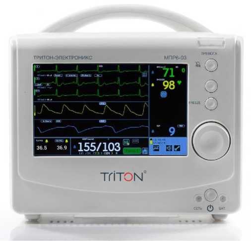
Рисунок 1 — Общий вид монитора в исполнении 1 (с дисплеем 7″)
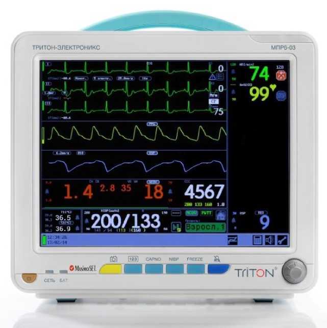
Рисунок 2 — Общий вид монитора в исполнении 2 (с дисплеем 12″)
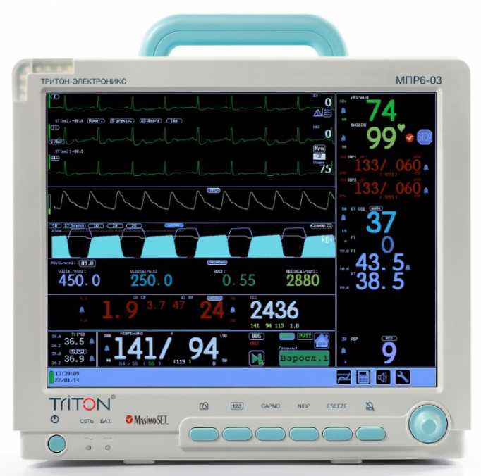
Рисунок 3 — Общий вид монитора в исполнении 3 (с дисплеем 15″)
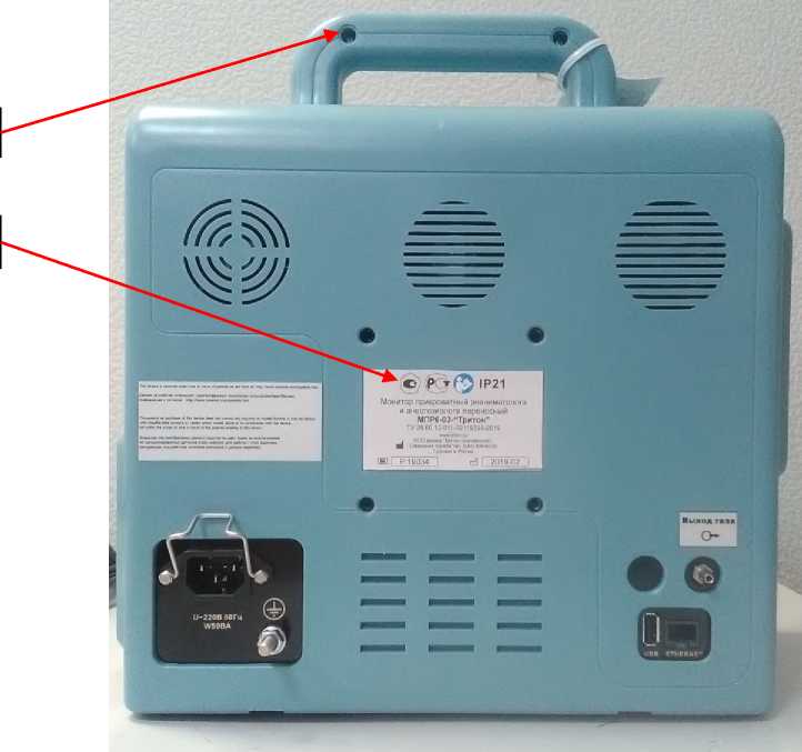
Рисунок 4 — Схема пломбировки от несанкционированного доступа (Б) и место нанесения знака утверждения типа (А)
Программное обеспечение
Программное обеспечение (далее — ПО) мониторов установлено в памяти внутреннего контроллера и служит для управления режимами работы, выбора встроенных измерительных и вспомогательных функций.
ПО реализовано без выделения метрологически значимой части.
Уровень защиты программного обеспечения «средний» в соответствии с
Р 50.2.077-2014.
Таблица 1 — Идентификационные данные программного обеспечения
|
Идентификационные данные (признаки) |
Значение |
|
Идентификационное наименование ПО |
MPR603 |
|
Номер версии (идентификационный номер ПО) |
не ниже 4.06 |
Технические характеристики
Таблица 2 — Метрологические характеристики
|
Наименование характеристики |
Значение |
|
Модуль пульсоксиметрии ТЭСМ.505008 |
|
|
Диапазон измерений отношения индексов модуляции (А) двух синфазномодулированных сигналов, выраженного в единицах сатурации (SpO2), % |
от 70 до 100 |
|
Пределы допускаемой абсолютной погрешности измерений отношения индексов модуляции (А) двух синфазномодулированных сигналов, выраженного в единицах сатурации (SpO2), % |
±2 |
|
Диапазон показаний частоты модуляции двух синфазномодулированных сигналов (PR), 1/мин |
от 15 до 350 |
|
Диапазон измерений частоты модуляции двух синфазномодулированных сигналов (PR), 1/мин |
от 30 до 250 |
|
Пределы допускаемой абсолютной погрешности измерений PR, 1/мин |
±1 |
|
Модуль пульсоксиметрии Masimo |
|
|
Диапазон измерений функционального SpO2, % |
от 70 до 100 |
|
Пределы допускаемой абсолютной погрешности измерений функционального SpO2, % |
±2 |
|
Диапазон показаний частоты пульса (PR), 1/мин |
от 25 до 240 |
|
Диапазон измерений частоты пульса (PR), 1/мин |
от 30 до 240 |
|
Пределы допускаемой абсолютной погрешности измерений частоты пульса (PR), 1/мин |
±1 |
|
Модуль кардиометрии |
|
|
Диапазон входных напряжений, размах, мВ |
от 0,05 до 10 |
|
Входной импеданс, МОм, не менее |
2,5 |
|
Коэффициент ослабления синфазного сигнала, дБ, не менее |
80 |
|
Напряжение внутренних шумов, приведенных к входу, мкВ, не более |
30 |
|
Диапазон показаний частоты сердечных сокращений (ЧСС), 1/мин |
от 12 до 350 |
|
Диапазон измерений частоты сердечных сокращений (ЧСС), 1/мин |
от 12 до 300 |
|
Пределы допускаемой абсолютной погрешности измерений ЧСС, 1/мин |
±1 |
|
Модуль термометрии |
|
Диапазон показаний температуры, °С |
от 0 до +50 |
|
Диапазон измерений температуры, °С |
от +32 до + 42 |
|
Пределы допускаемой абсолютной погрешности измерений температуры, °С |
±0,1 |
Продолжение таблицы 2
|
Модуль неинвазивного измерения артериального давления |
|
|
Диапазоны измерений давления в манжете, мм рт. ст. |
от 0 до 300 |
|
Пределы допускаемой абсолютной погрешности измерений давления в манжете, мм рт.ст. |
±3 |
|
Максимальное давление в манжете: — для взрослых, мм рт. ст., не более — для новорожденных, мм рт. ст., не более |
300 150 |
|
Модуль инвазивного измерения давления |
|
|
Диапазон измерений давления инвазивным способом, мм рт.ст. |
от -50 до +300 |
|
Пределы допускаемой погрешности измерений, относительной в диапазоне от 101 до 300 мм рт. ст., % абсолютной в диапазоне от -50 до 100 мм рт. ст., мм рт. ст. |
±2 ±2 |
|
Модуль измерения параметров дыхания |
|
|
Диапазон показаний частоты дыхания, 1/мин |
от 5 до 160 |
|
Диапазон измерений частоты дыхания, 1/мин |
от 6 до 160 |
|
Пределы допускаемой абсолютной погрешности измерений частоты дыхания, 1/мин |
±3 |
|
Модуль газоанализа дыхательной смеси |
|
|
Диапазоны измерений: процентного содержания кислорода СОз, % парциального давления СО2, мм рт. ст. процентного содержания О2, % |
от 0 до 15 от 0 до 115 от 0 до 100 |
|
Пределы допускаемой погрешности измерений: процентного содержания СО2: — абсолютной в диапазоне от 0 до 5 % включ., % — относительной в диапазоне св. 5 до 10 % включ., % — относительной в диапазоне св. 10 до 15%, % парциального давления СО2: — абсолютной в диапазоне от 0 до 40 мм рт. ст. включ., мм рт. ст. — относительной в диапазоне св. 40 до 80 мм рт. ст. включ., % — относительной в диапазоне св. 80 до 115 мм рт. ст.), % Пределы допускаемой абсолютной погрешности измерений процентного содержания О2, % |
±0,2 ±4 ±6 ±1,5 ±4 ±6 ±2 |
Таблица 3 — Основные технические характеристики
|
Наименование характеристики |
Значение |
|
1 |
2 |
|
Габаритные размеры (ширинахвысотахглубина), не более, мм с дисплеем 7″ (исполнение 1) |
250x220x200 |
|
с дисплеем 12” (исполнение 2) |
310x290x185 |
|
с дисплеем 15” (исполнение 3) |
370x360x200 |
|
Наименование характеристики |
Значение |
|
1 |
2 |
|
Масса, не более, кг |
|
|
с дисплеем 7″ (исполнение 1) |
3,5 |
|
с дисплеем 12” (исполнение 2) |
6,5 |
|
с дисплеем 15” (исполнение 3) |
7,5 |
|
Напряжение питания, В |
220 ± 22 |
Продолжение таблицы 3
|
1 |
2 |
|
Рабочие условия применения: — температура окружающей среды, °С — относительная влажность воздуха, % — атмосферное давление, кПа |
от +10 до +35 от 40 до 80 от 79,99 до 106,65 |
Знак утверждения типа
наносится на заднюю панель мониторов методом печати на этикетку и на титульный лист руководства по эксплуатации типографским способом.
Комплектность
Таблица 4 — Комплектность средства измерений
|
Наименование |
Обозначение |
Колич., шт. |
|
|
1 |
2 |
3 |
|
|
I. Монитор прикроватный реаниматолога и анестезиолога переносный МПР6-03-«Тритон», вариант исполнения 1: |
|||
|
1 |
Электронный блок, в составе: |
ТЭСМ.556002 |
1 |
|
1.1 |
Модуль пульсоксиметрический |
ТЭСМ.505008 |
1 |
|
1.2 |
Модуль термометрии |
ТЭСМ.505008 |
1 |
|
1.3 |
Модуль кардиометрии |
ТЭСМ.505008 |
1 |
|
1.4 |
Модуль измерения параметров дыхания |
ТЭСМ.505008 |
1 |
|
1.5 |
Модуль неинвазивного измерения артериального давления |
ТЭСМ.555021 |
1 |
|
1.6 |
Модуль неинвазивного измерения сердечного выброса (при необходимости) |
ТЭСМ.555021 |
1 |
|
1.7 |
Модуль принтера (при необходимости) |
ТЭСМ.555006 |
|
|
1.8 |
Встроенный аккумулятор |
1 |
|
|
1.9 |
Кабель питания |
ТЭСМ.174007 |
1 |
|
Наименование |
Обозначение |
Колич., шт. |
|
|
1 |
2 |
3 |
|
|
2 |
Модуль газоанализа дыхательной смеси (без отбора пробы) (при необходимости), в составе: — датчик СО2 в прямом потоке (при необходимости) — 1 шт. — вентиляционный адаптер взрослый/детский (при необходимости) — 1 шт. — вентиляционный адаптер детский/неонатальный (при необходимости) — 1 шт. |
ТЭСМ.506001 |
— |
|
3 |
Датчик оптоэлектронный пульсоксиметрический пальцевый прищепочный ДОПпп — Тритон (при необходимости) |
Рег. удостоверение №ФСР 2011/11675 ООО фирма «Тритон-ЭлектроникС», Россия |
— |
|
1 |
2 |
3 |
|
|
4 |
Датчик оптоэлектронный пульсоксиметрический неонатальный ДОПн — Тритон (при необходимости) |
Рег. удостоверение №ФСР 2011/11675 ООО фирма «Тритон-ЭлектроникС», Россия |
— |
|
5 |
Датчик пульсоксиметрический педиатрический, клипса (при необходимости) |
ТЭСМ.096011 |
— |
|
6 |
Датчик пульсоксиметрический педиатрический, резиновый (при необходимости) |
ТЭСМ.096012 |
— |
|
7 |
Датчик пульсоксиметрический взрослый, резиновый (при необходимости) |
ТЭСМ.096016 |
— |
|
8 |
Датчик пульсоксиметрический педиатрический, одноразовый (при необходимости) |
DI-2211-5, «Envitec-Wismar GmbH», Германия |
— |
|
9 |
Датчик пульсоксиметрический детский/неонатальный, одноразовый (при необходимости) |
DW-2211-6, «Envitec-Wismar GmbH», Германия |
— |
|
10 |
Датчик пульсоксиметрический неонатальный, одноразовый (при необходимости) |
DN-2211-6, «Envitec-Wismar GmbH», Германия |
— |
|
11 |
Датчик пульсоксиметрический (при необходимости) |
Рег. удостоверение №ФСЗ 2012/13363 «Envitec-Wismar GmbH», Германия |
— |
|
12 |
Переходник датчика пульсоксиметрического (при необходимости) |
ТЭСМ.534014 |
— |
|
13 |
Кабель пациента (при необходимости) |
РМ501.00.120 |
— |
|
14 |
Кабель пациента (при необходимости) |
РМ501.00.120-01 |
— |
|
15 |
Кабель пациента (при необходимости) |
РМ501.00.120-03 |
— |
|
16 |
Кабель пациента (при необходимости) |
РМ501.00.120-04 |
— |
|
17 |
Датчик температуры поверхностный (при необходимости) |
РМ501.25.000 |
— |
|
18 |
Датчик температуры внутриполостной (при необходимости) |
РМ321.21.000 |
— |
|
19 |
Датчик температуры одноразовый (при необходимости) |
ТЭСМ.096019 |
— |
|
20 |
Датчик температуры одноразовый, универсальный (при необходимости) |
ТЭСМ.096020 |
— |
|
21 |
Переходник датчика температуры (при необходимости) |
ТЭСМ.096018 |
|
1 |
2 |
3 |
|
|
22 |
Манжета SoftCheck (при необходимости) |
«Statcorp Medical», США |
— |
Продолжение таблицы 4
|
1 |
2 |
3 |
|
|
23 |
Манжета LD-Cuff (при необходимости) |
Рег. удостоверение №ФСЗ 2012/11653 «LITTLE DOCTOR INTERNATIONAL», Сингапур |
— |
|
24 |
Манжета НИАД (при необходимости) |
ТЭСМ.536404 |
— |
|
25 |
Манжета для определения неинвазивного артериального давления (при необходимости) |
Рег. удостоверение №РЗН 2015/2702 «Shenzhen EMS Life Technology Co., Ltd» КНР |
— |
|
26 |
Шланг для манжеты (при необходимости) |
ТЭСМ.536128 |
— |
|
27 |
ЭКГ-электроды одноразовые для диагностики (при необходимости) |
Рег. удостоверение №ФСЗ 2008/02776 «Ambu A/S», Дания |
— |
|
28 |
Электроды для ЭКГ (при необходимости) |
Рег. удостоверение №ФСЗ 2010/07536 «FIAB SpA», Италия |
— |
|
29 |
Кабель питания для подключения к внешнему источнику постоянного тока (только для приборов с универсальным питанием) (при необходимости) |
ТЭСМ.324001 |
— |
|
30 |
Кабель питания для подключения к внешнему источнику постоянного тока (только для приборов с универсальным питанием) (при необходимости) |
ТЭСМ.534028 |
— |
|
31 |
Кабель питания для подключения к внешнему источнику постоянного тока (только для приборов с универсальным питанием) (при необходимости) |
ТЭСМ.534028-01 |
— |
|
32 |
Установочное оборудование (при необходимости) |
ТЭСМ.533002-02 |
— |
|
33 |
Тележка транспортная (при необходимости) |
ТЭСМ.533009-02 |
— |
|
Запасные части: |
|||
|
34 |
Предохранитель ВПТ6-7-1А |
АГО 0481.304ТУ |
— |
|
Эксплуатационная документация: |
|||
|
35 |
Руководство по эксплуатации МПР6-03 (исполнение 1) |
РМ501.01.000-01-01 РЭ |
— |
|
36 |
Паспорт МПР6-03 |
РМ501.01.000-01-01 ПС |
— |
Упаковка:
|
1 |
2 |
3 |
|
Упаковка транспортная |
ТЭСМ.023001 |
— |
|
37 или |
||
|
Упаковка транспортная |
ТЭСМ.533008-02 |
— |
|
1 |
2 |
3 |
|
|
II. Монитор прикроватный реаниматолога и анестезиолога переносный МПР6-03-«Тритон», вариант исполнения 2: |
|||
|
1 |
Электронный блок, в составе: |
ТЭСМ.526001 |
1 |
|
1.1 |
Модуль пульсоксиметрии или Модуль пульсоксиметрии |
ТЭСМ.505008 MSX-2040 MasimoSet |
1 1 |
|
1.2 |
Модуль кардиометрии |
ТЭСМ.505008 |
1 |
|
1.3 |
Модуль термометрии |
ТЭСМ.505008 |
1 |
|
1.4 |
Модуль измерения параметров дыхания |
ТЭСМ.505008 |
1 |
|
1.5 |
Модуль неинвазивного измерения артериального давления |
ТЭСМ.555021 |
1 |
|
1.6 |
Модуль неинвазивного измерения сердечного выброса (при необходимости) |
ТЭСМ.555021 |
1 |
|
1.7 |
Модуль инвазивного измерения давления (при необходимости) |
ТЭСМ.535015 |
1 |
|
1.8 |
Модуль газоанализа дыхательной смеси (при необходимости) или Модуль газоанализа дыхательной смеси (при необходимости) |
ТЭСМ.536141 AION 02-31 Multigas Analyzer, AION 03-31 Multigas Analyzer, ТЭСМ.706105 |
1 1 |
|
1.9 |
Модуль мониторинга параметров респираторной механики и энергообмена (при необходимости) |
ТЭСМ.705055 |
1 |
|
1.10 |
Модуль принтера (при необходимости) |
ТЭСМ.555006 |
1 |
|
1.11 |
Встроенный аккумулятор |
1 |
|
|
1.12 |
Кабель питания |
ТЭСМ.174007 |
1 |
|
2 |
Модуль газоанализа дыхательной смеси (без отбора пробы) (при необходимости), в составе: — датчик СО2 в прямом потоке (при необходимости) — 1 шт. — вентиляционный адаптер взрослый/детский (при необходимости) — 1 шт. — вентиляционный адаптер детский/неонатальный (при необходимости) — 1 шт. |
ТЭСМ.506001 |
— |
|
3 |
Модуль оценки глубины анестезии (при необходимости) |
Рег. удостоверение №РЗН 2015/2595 ООО фирма «Тритон-ЭлектроникС», Россия |
— |
Лист № 13
Всего листов 26
|
1 |
2 |
3 |
|
|
4 |
Датчик оптоэлектронный пульсоксиметрический пальцевый прищепочный ДОПпп — Тритон (при необходимости) |
Рег. удостоверение №ФСР 2011/11675 ООО фирма «Тритон-ЭлектроникС» |
— |
|
5 |
Датчик оптоэлектронный пульсоксиметрический неонатальный ДОПн — Тритон (при необходимости) |
Рег. удостоверение №ФСР 2011/11675 ООО фирма «Тритон-ЭлектроникС» |
— |
|
6 |
Датчик пульсоксиметрический педиатрический, одноразовый (при необходимости) |
DI-2211-5, «Envitec-Wismar GmbH», Германия |
— |
|
7 |
Датчик пульсоксиметрический детский/неонатальный, одноразовый (при необходимости) |
DW-2211-6, «Envitec-Wismar GmbH», Германия |
— |
|
8 |
Датчик пульсоксиметрический неонатальный, одноразовый (при необходимости) |
DN-2211-6, «Envitec-Wismar GmbH», Германия |
— |
|
9 |
Датчик пульсоксиметрический (при необходимости) |
Рег. удостоверение №ФСЗ 2012/13363 «Envitec-Wismar GmbH», Германия |
— |
|
10 |
Датчик пульсоксиметрический педиатрический, клипса (при необходимости) |
ТЭСМ.096011 |
— |
|
11 |
Датчик пульсоксиметрический педиатрический, резиновый (при необходимости) |
ТЭСМ.096012 |
— |
|
12 |
Датчик пульсоксиметрический взрослый, резиновый (при необходимости) |
ТЭСМ.096016 |
— |
|
13 |
Датчик LNOP для пульсоксиметрии (при необходимости): 1269, 1276 |
Рег. удостоверения №ФСЗ 2009/04037 «Masimo Corporation», США |
— |
|
14 |
Датчик LNCS для пульсоксиметрии (при необходимости): 1864, 1895 |
— |
|
|
15 |
Кабель LNOP (при необходимости): 1005, 1006, 1173 |
— |
|
|
16 |
Кабель LNCS (при необходимости): 1814, 2017 |
— |
|
|
17 |
Датчик LNOP для пульсоксиметрии (при необходимости): 1001, 1025 |
Рег. удостоверения №ФСЗ 2009/04038 «Masimo Corporation», США |
— |
|
18 |
Датчик LNCS для пульсоксиметрии (при необходимости): 1859, 1860 |
— |
|
|
19 |
Датчик LNOP для пульсоксиметрии (при необходимости): 1798, 1651 |
Рег. удостоверения №ФСЗ 2009/04039 «Masimo Corporation», |
— |
|
1 |
2 |
3 |
|
|
20 |
Датчик LNCS для пульсоксиметрии (при необходимости): 2328, 2329 |
— |
|
|
21 |
Датчик LNCS для пульсоксиметрии (при необходимости): 1896 |
Рег. удостоверения №ФСЗ 2009/04041 «Masimo Corporation», США |
— |
|
22 |
Кабель LNCS (при необходимости): 1816 |
— |
|
|
23 |
Датчик LNCS для пульсоксиметрии (при необходимости): 1863, 2330 |
Рег. удостоверения №ФСЗ 2009/04042 «Masimo Corporation», США |
— |
|
24 |
Датчик LNOP для пульсоксиметрии (при необходимости): 1800, 1970 |
— |
|
|
25 |
Датчик LNCS для пульсоксиметрии (при необходимости): 2258 |
Рег. удостоверения №ФСЗ 2009/04043 «Masimo Corporation», США |
— |
|
26 |
Датчик LNOP для пульсоксиметрии (при необходимости): 1794, 1544 |
— |
|
|
27 |
Кабель LNCS (при необходимости): 2013 |
— |
|
|
28 |
Датчик RD SET DCI для пульсоксиметрии (при необходимости): 4050 |
«Masimo Corporation», США |
— |
|
29 |
Кабель RD SET MD14-05 (при необходимости): 4080 |
— |
|
|
30 |
Переходник датчика пульсоксиметрического (при необходимости) |
ТЭСМ.534014 |
— |
|
31 |
Кабель пациента (при необходимости) |
РМ501.00.120 |
— |
|
32 |
Кабель пациента (при необходимости) |
РМ501.00.120-02 |
— |
|
33 |
Кабель пациента (при необходимости) |
РМ501.00.120-03 |
— |
|
34 |
Кабель пациента (при необходимости) |
РМ501.00.120-05 |
— |
|
35 |
Датчик температуры поверхностный (при необходимости) |
РМ501.25.000 |
— |
|
36 |
Датчик температуры внутриполостной (при необходимости) |
РМ321.21.000 |
— |
|
37 |
Датчик температуры одноразовый (при необходимости) |
ТЭСМ.096019 |
— |
|
38 |
Датчик температуры одноразовый, универсальный (при необходимости) |
ТЭСМ.096020 |
— |
|
39 |
Переходник датчика температуры (при необходимости) |
ТЭСМ.096018 |
— |
|
40 |
Манжета SoftCheck (при необходимости) |
«Statcorp Medical», США |
— |
|
1 |
2 |
3 |
|
|
41 |
Манжета LD-Cuff (при необходимости) |
Рег. удостоверение №ФСЗ 2012/11653 «LITTLE DOCTOR INTERNATIONAL», Сингапур |
— |
|
42 |
Манжета для определения неинвазивного артериального давления (при необходимости) |
Рег. удостоверение №РЗН 2015/2702 «Shenzhen EMS Life Technology Co., Ltd», КНР |
— |
|
43 |
Манжета НИАД (при необходимости) |
ТЭСМ.536404 |
— |
|
44 |
Шланг для манжеты (при необходимости) |
ТЭСМ.536128 |
— |
|
45 |
Электроды медицинские с принадлежностями (при необходимости) |
Рег. удостоверение №ФСЗ 2012/12612 «Covidien Llc», США |
— |
|
46 |
ЭКГ-электроды одноразовые для диагностики (при необходимости) |
Рег. удостоверение №ФСЗ 2008/02776 «Ambu A/S», Дания |
— |
|
47 |
Электроды для ЭКГ (при необходимости) |
Рег. удостоверение №ФСЗ 2010/07536 «FIAB SpA», Италия |
— |
|
48 |
Соединители (при необходимости): жесткие, эластомерные, гибкие, шарнирные, прямые, угловые, Т-образные, Y-образные, адаптеры |
Рег. удостоверение №ФСЗ 2009/03551 «ИНТЕРСЕРДЖИКАЛ», Великобритания, Литва |
— |
|
49 |
Переходники (при необходимости) |
Рег. удостоверение №РЗН 2013/1311 «Flexicare Medical Limited», Соединенное Королевство |
— |
|
50 |
Удлинитель инфузионных насосов (PPI) (при необходимости) |
Рег. удостоверение №ФСЗ 2010/06121 «BALTON Ltd.», Польша |
— |
|
51 |
Комплект Filter Line (гидрофобный фильтр, носовые канюли, пробозаборный канал, опознавательный ключ, соединительные линии, байтблок, воздухозаборный адаптер) (при необходимости) |
Рег. Удостоверение №РЗН 2014/2197 «Oridion Medical», Израиль |
— |
|
52 |
Комплект для измерения СО2 (при необходимости): — FilterLine, — магистраль FilterLine, — адаптер воздуховода |
Рег. удостоверение №РЗН 2014/2009 «Philips Medizin Systeme Boblingen GmbH», Германия |
— |
|
1 |
2 |
3 |
|
|
53 |
Носовые канюли (при необходимости) |
Рег. удостоверение №РЗН 2014/2197 «Oridion Medical», Израиль |
— |
|
54 |
Наборы для контроля давления с преобразователем КОМБИТРАНС (при необходимости) |
Рег. удостоверение №РЗН 2013/245 «В. BRAUN Melsungen AG», Г ермания |
— |
|
55 |
Преобразователи КОМБИТРАНС в комплекте с краном ЭКСАДИН (при необходимости) |
— |
|
|
56 |
Пластина для крепления преобразователей КОМБИТРАНС (при необходимости) |
— |
|
|
57 |
Держатель Комби-холдер для преобразователей КОМБИТРАНС (при необходимости) |
— |
|
|
58 |
Многоразовый преобразователь давления СенсоНор 844 (при необходимости) |
— |
|
|
59 |
Набор для контроля давления КОМБИДИН (при необходимости) |
— |
|
|
60 |
Купол СЕНСОНОР (при необходимости) |
— |
|
|
61 |
Кабель соединительный КОМБИТРАНС (при необходимости) |
Рег. удостоверение №РЗН 2013/245 «B.BRAUN Melsungen AG», Германия. «Unimed Medical Supplies, Inc.», Китай |
— |
|
62 |
Датчик потока (при необходимости) |
Рег. Удостоверение №ФСЗ 2012/13363 «Envitec-Wismar GmbH», Германия |
— |
|
63 |
Маска для неинвазивной вентиляции дыхательная ClassicStar, NovaStar (при необходимости) |
Рег. удостоверение №ФСЗ 2011/09227 «Draeger Medical GmbH», Германия |
— |
|
64 |
Маска для вентиляции легких (при необходимости): маски для неинвазивной вентиляции, маски для СРАР |
Рег. удостоверение №ФСЗ 2009/03551 «Intersurgical Ltd», Великобритания |
— |
|
65 |
Кислородная маска (при необходимости) |
Рег. удостоверение №ФСЗ 2007/00742 «Fisher & Paykel Healthcare Limited», Новая Зеландия |
— |
|
1 |
2 |
3 |
|
|
66 |
Маска, варианты исполнения (при необходимости): Willow, Vio, Full Face Mask, размеры S, M, L |
Рег. удостоверение №ФСЗ 2012/11759 «BMC Medical Co.,Ltd», КНР |
— |
|
67 |
Маска (при необходимости) |
Рег. удостоверение №ФСЗ 2012/12634 «Armstrong Medical Limited», Великобритания |
— |
|
68 |
Кабель питания для подключения к внешнему источнику постоянного тока (только для приборов с универсальным питанием) (при необходимости) |
ТЭСМ.324001 |
— |
|
69 |
Кабель питания для подключения к внешнему источнику постоянного тока (только для приборов с универсальным питанием) (при необходимости) |
ТЭСМ.534028 |
— |
|
70 |
Кабель питания для подключения к внешнему источнику постоянного тока (только для приборов с универсальным питанием) (при необходимости) |
ТЭСМ.534028-01 |
— |
|
71 |
Установочное оборудование (при необходимости) |
ТЭСМ.533002-02 |
— |
|
72 |
Установочное оборудование (при необходимости) |
ТЭСМ.533002-04 |
— |
|
73 |
Установочное оборудование (при необходимости) |
ТЭСМ.533002-05 |
— |
|
74 |
Тележка транспортная (при необходимости) |
ТЭСМ.533009-01 |
— |
|
Запасные части: |
|||
|
75 |
Предохранитель ВПТ6-7-1А |
АГО 0481.304ТУ |
— |
|
76 |
Влагоотделитель |
60-13100-00 DRYLINE Water Trap, Adult «ARTEMA», Швеция |
— |
|
Эксплуатационная документация: |
|||
|
77 |
Руководство по эксплуатации МПР6-03 (исполнение 2) |
РМ501.01.000-01-01 РЭ |
— |
|
78 |
Паспорт МПР6-03 |
РМ501.01.000-01-01 ПС |
— |
|
Упаковка: |
|||
|
79 |
Упаковка транспортная или Упаковка транспортная |
ТЭСМ.533001-01 ТЭСМ.533008-01 |
— |
|
III. Монитор прикроватный реаниматолога и анестезиолога переносный МПР6-03-«Тритон», вариант исполнения 3: |
|||
|
1 |
Электронный блок, в составе: |
ТЭСМ.516000 |
1 |
|
1 |
2 |
3 |
|
Модуль пульсоксиметрии 1.1 или |
ТЭСМ.505008 |
1 |
|
Модуль пульсоксиметрии |
MSX-2040 MasimoSet |
1 |
Продолжение таблицы 4
|
1 |
2 |
3 |
|
|
1.2 |
Модуль кардиометрии |
ТЭСМ.505008 |
1 |
|
1.3 |
Модуль термометрии |
ТЭСМ.505008 |
1 |
|
1.4 |
Модуль измерения параметров дыхания |
ТЭСМ.505008 |
1 |
|
1.5 |
Модуль неинвазивного измерения артериального давления |
ТЭСМ.555021 |
1 |
|
1.6 |
Модуль неинвазивного измерения сердечного выброса (при необходимости) |
ТЭСМ.555021 |
1 |
|
1.7 |
Модуль инвазивного измерения давления (при необходимости) |
ТЭСМ.535015 |
1 |
|
1.8 |
Модуль газоанализа дыхательной смеси (при необходимости) или Модуль газоанализа дыхательной смеси (при необходимости) |
ТЭСМ.536141 AION 02-31 Multigas Analyzer, AION 03-31 Multigas Analyzer, ТЭСМ.706105 |
1 1 |
|
1.9 |
Модуль мониторинга параметров респираторной механики и энергообмена (при необходимости) |
ТЭСМ.705055 |
1 |
|
1.10 |
Модуль принтера (при необходимости) |
ТЭСМ.555006 |
1 |
|
1.11 |
Встроенный аккумулятор |
1 |
|
|
1.12 |
Кабель питания |
ТЭСМ.174007 |
1 |
|
2 |
Модуль газоанализа дыхательной смеси (без отбора пробы) (при необходимости), в составе: — датчик СО2 в прямом потоке (при необходимости) — 1 шт. — вентиляционный адаптер взрослый/детский (при необходимости) — 1 шт. — вентиляционный адаптер детский/неонатальный (при необходимости) — 1 шт. |
ТЭСМ.506001 |
— |
|
3 |
Модуль оценки глубины анестезии (при необходимости) |
Рег. удостоверение №РЗН 2015/2595 ООО фирма «Тритон-ЭлектроникС», Россия |
— |
|
1 |
2 |
3 |
|
|
4 |
Датчик оптоэлектронный пульсоксиметрический пальцевый прищепочный ДОПпп — Тритон (при необходимости) |
Рег. удостоверение №ФСР 2011/11675 ООО фирма «Тритон-ЭлектроникС», Россия |
— |
|
5 |
Датчик оптоэлектронный пульсоксиметрический неонатальный ДОПн — Тритон (при необходимости) |
Рег. удостоверение №ФСР 2011/11675 ООО фирма «Тритон-ЭлектроникС», Россия |
— |
Продолжение таблицы 4
|
1 |
2 |
3 |
|
|
6 |
Датчик пульсоксиметрический педиатрический, одноразовый (при необходимости) |
DI-2211-5, «Envitec-Wismar GmbH», Германия |
— |
|
7 |
Датчик пульсоксиметрический, детский/неонатальный, одноразовый (при необходимости) |
DW-2211-6, «Envitec-Wismar GmbH», Германия |
— |
|
8 |
Датчик пульсоксиметрический неонатальный, одноразовый (при необходимости) |
DN-2211-6, «Envitec-Wismar GmbH», Германия |
— |
|
9 |
Датчик пульсоксиметрический (при необходимости) |
Рег. удостоверение №ФСЗ 2012/13363 «Envitec-Wismar GmbH», Германия |
— |
|
10 |
Датчик пульсоксиметрический педиатрический, клипса (при необходимости) |
ТЭСМ.096011 |
— |
|
11 |
Датчик пульсоксиметрический педиатрический, резиновый (при необходимости) |
ТЭСМ.096012 |
— |
|
12 |
Датчик пульсоксиметрический взрослый, резиновый (при необходимости) |
ТЭСМ.096016 |
— |
|
13 |
Датчик LNOP для пульсоксиметрии (при необходимости): 1269, 1276 |
Рег. удостоверения №ФСЗ 2009/04037 «Masimo Corporation», США |
— |
|
14 |
Датчик LNCS для пульсоксиметрии (при необходимости): 1864, 1895 |
— |
|
|
15 |
Кабель LNOP (при необходимости): 1005, 1006, 1173 |
— |
|
|
16 |
Кабель LNCS (при необходимости): 1814, 2017 |
— |
|
|
17 |
Датчик LNOP для пульсоксиметрии (при необходимости): 1001, 1025 |
Рег. удостоверения №ФСЗ 2009/04038 «Masimo Corporation», США |
— |
|
18 |
Датчик LNCS для пульсоксиметрии (при необходимости): 1859, 1860 |
— |
|
1 |
2 |
3 |
|
|
19 |
Датчик LNOP для пульсоксиметрии (при необходимости): 1798, 1651 |
Рег. удостоверения №ФСЗ 2009/04039 «Masimo Corporation», США |
— |
|
20 |
Датчик LNCS для пульсоксиметрии (при необходимости): 2328, 2329 |
— |
|
|
21 |
Датчик LNCS для пульсоксиметрии (при необходимости): 1896 |
Рег. удостоверения №ФСЗ 2009/04041 «Masimo Corporation», США |
— |
|
22 |
Кабель LNCS (при необходимости): 1816 |
— |
|
1 |
2 |
3 |
|
|
23 |
Датчик LNCS для пульсоксиметрии (при необходимости): 1863, 2330 |
Рег. удостоверения №ФСЗ 2009/04042 «Masimo Corporation», США |
— |
|
24 |
Датчик LNOP для пульсоксиметрии (при необходимости): 1800, 1970 |
— |
|
|
25 |
Датчик LNCS для пульсоксиметрии (при необходимости): 2258 |
Рег. удостоверения №ФСЗ 2009/04043 «Masimo Corporation», США |
— |
|
26 |
Датчик LNOP для пульсоксиметрии (при необходимости): 1794, 1544 |
— |
|
|
27 |
Кабель LNCS (при необходимости): 2013 |
— |
|
|
28 |
Датчик RD SET DCI для пульсоксиметрии (при необходимости): 4050 |
«Masimo Corporation», США |
— |
|
29 |
Кабель RD SET MD14-05 (при необходимости): 4080 |
«Masimo Corporation», США |
— |
|
30 |
Переходник датчика пульсоксиметрического (при необходимости) |
ТЭС.534014 |
— |
|
31 |
Кабель пациента (при необходимости) |
РМ501.00.120 |
— |
|
32 |
Кабель пациента (при необходимости) |
РМ501.00.120-02 |
— |
|
33 |
Кабель пациента (при необходимости) |
РМ501.00.120-03 |
— |
|
34 |
Кабель пациента (при необходимости) |
РМ501.00.120-05 |
— |
|
35 |
Датчик температуры поверхностный (при необходимости) |
РМ501.25.000 |
— |
|
36 |
Датчик температуры внутриполостной (при необходимости) |
РМ321.21.000 |
— |
|
37 |
Датчик температуры одноразовый (при необходимости) |
ТЭСМ.096019 |
— |
|
38 |
Датчик температуры одноразовый, универсальный (при необходимости) |
ТЭСМ.096020 |
— |
|
39 |
Переходник датчика температуры (при необходимости) |
ТЭСМ.096018 |
— |
|
40 |
Манжета LD-Cuff (при необходимости) |
Рег. удостоверение №ФСЗ 2012/11653 «LITTLE DOCTOR INTERNATIONAL», Сингапур |
— |
|
41 |
Манжета SoftCheck (при необходимости) |
«Statcorp Medical», США |
— |
|
42 |
Манжета для определения неинвазивного артериального давления (при необходимости) |
Рег. удостоверение №РЗН 2015/2702 «Shenzhen EMS Life Technology Co., Ltd» КНР |
— |
|
43 |
Манжета НИАД (при необходимости) |
ТЭСМ.536404 |
— |
|
1 |
2 |
3 |
|
|
44 |
Шланг для манжеты (при необходимости) |
ТЭСМ.536128 |
— |
|
45 |
Электроды медицинские с принадлежностями (при необходимости) |
Рег. удостоверение №ФСЗ 2012/12612 «Covidien Llc», США |
— |
|
46 |
ЭКГ-электроды одноразовые для диагностики (при необходимости) |
Рег. удостоверение №ФСЗ 2008/02776 «Ambu A/S», Дания |
— |
|
47 |
Электроды для ЭКГ (при необходимости) |
Рег. удостоверение №ФСЗ 2010/07536 «FIAB SpA», Италия |
— |
|
48 |
Соединители (при необходимости): жесткие, эластомерные, гибкие, шарнирные, прямые, угловые, Т-образные, Y-образные, адаптеры |
Рег. удостоверение №ФСЗ 2009/03551 «ИНТЕРСЕРДЖИКАЛ», Великобритания, Литва |
— |
|
49 |
Переходники (при необходимости) |
Рег. удостоверение №РЗН 2013/1311 «Flexicare Medical Limited», Соединенное Королевство |
— |
|
50 |
Удлинитель инфузионных насосов (PPI) (при необходимости) |
Рег. удостоверение №ФСЗ 2010/06121 «BALTON Ltd.», Польша |
— |
|
51 |
Комплект Filter Line (гидрофобный фильтр, носовые канюли, пробозаборный канал, опознавательный ключ, соединительные линии, байтблок, воздухозаборный адаптер) (при необходимости) |
Рег. удостоверение №РЗН 2014/2197 «Oridion Medical», Израиль |
— |
|
52 |
Комплект для измерения СО2 (при необходимости): — FilterLine, — магистраль FilterLine, — адаптер воздуховода |
Рег. удостоверение №РЗН 2014/2009 «Philips Medizin Systeme Boblingen GmbH», Германия |
— |
|
53 |
Носовые канюли (при необходимости) |
Рег. удостоверение №РЗН 2014/2197 «Oridion Medical», Израиль |
— |
|
54 |
Наборы для контроля давления с преобразователем КОМБИТРАНС (при необходимости) |
Рег. удостоверение №РЗН 2013/245 «В. BRAUN Melsungen AG», Г ермания |
— |
|
55 |
Преобразователи КОМБИТРАНС в комплекте с краном ЭКСАДИН (при необходимости) |
— |
|
|
56 |
Пластина для крепления преобразователей КОМБИТРАНС (при необходимости) |
— |
|
|
57 |
Держатель Комби-холдер для преобразователей КОМБИТРАНС (при необходимости) |
— |
|
1 |
2 |
3 |
|
|
58 |
Многоразовый преобразователь давления СенсоНор 844 (при необходимости) |
— |
|
|
59 |
Набор для контроля давления КОМБИДИН (при необходимости) |
— |
|
|
60 |
Купол СЕНСОНОР (при необходимости) |
— |
|
|
61 |
Кабель соединительный КОМБИТРАНС (при необходимости) |
Рег. удостоверение №РЗН 2013/245 «B.BRAUN Melsungen AG», Германия. «Unimed Medical Supplies, Inc.», Китай |
— |
|
62 |
Датчик потока (при необходимости) |
Рег. удостоверение №ФСЗ 2012/13363 «Envitec-Wismar GmbH |
— |
|
63 |
Маска для неинвазивной вентиляции дыхательная ClassicStar, NovaStar (при необходимости) |
Рег. удостоверение №ФСЗ 2011/09227 «Draeger Medical GmbH», Германия |
— |
|
64 |
Маска для вентиляции легких (при необходимости): маски для неинвазивной вентиляции, маски для СРАР |
Рег. удостоверение №ФСЗ 2009/03551 «Intersurgical Ltd», Великобритания |
— |
|
65 |
Кислородная маска (при необходимости) |
Рег. удостоверение №ФСЗ 2007/00742 «Fisher & Paykel Healthcare Limited», Новая Зеландия |
— |
|
66 |
Маска, варианты исполнения (при необходимости): Willow, Vio, Full Face Mask, размеры S, M, L |
Рег. удостоверение №ФСЗ 2012/11759 «BMC Medical Co.,Ltd», КНР |
— |
|
67 |
Маска (при необходимости) |
Рег. удостоверение №ФСЗ 2012/12634 «Armstrong Medical Limited», Великобритания |
— |
|
68 |
Установочное оборудование (при необходимости) |
ТЭСМ.533002 |
— |
|
69 |
Тележка транспортная (при необходимости) |
ТЭСМ.533009 |
— |
|
Запасные части: |
|||
|
70 |
Предохранитель ВПТ6-7-1А |
АГО 0481.304ТУ |
— |
|
1 |
2 |
3 |
|
|
71 |
Влагоотделитель |
60-13100-00 DRYLINE Water Trap, Adult «ARTEMA», Швеция |
— |
Продолжение таблицы 4
|
1 |
2 |
3 |
|
|
Эксплуатационная документация: |
|||
|
72 |
Руководство по эксплуатации МПР6-03 (исполнение 3) |
РМ501.01.000-01-01 РЭ |
— |
|
73 |
Паспорт МПР6-03 |
РМ501.01.000-01-01 ПС |
— |
|
Упаковка: |
|||
|
74 |
Упаковка транспортная или Упаковка транспортная |
ТЭСМ.533001 ТЭСМ.533008 |
— |
|
Примечание — По согласованию с заказчиком определяется исполнение и комплектность прибора. |
Сведения о методах измерений
приведены в разделе 4 Руководства по эксплуатации РМ501.01.000-01-01 РЭ.
Нормативные документы
ГОСТ Р 50444-92 Приборы, аппараты и оборудование медицинские. Общие технические условия
ГОСТ 20790-93 Приборы, аппараты и оборудование медицинские. Общие технические условия
ГОСТ 30324.30-2002 Изделия медицинские электрические. Часть 2. Частные требования безопасности к приборам для автоматического контроля давления крови косвенным методом
ГОСТ Р 50267.34-95 Изделия медицинские электрические. Часть 2. Частные требования безопасности к приборам для прямого мониторинга кровяного давления
ГОСТ 31515.3-2012 Сфигмоманометры (измерители артериального давления) неинвазивные. Часть 3. Дополнительные требования к электромеханическим системам измерения давления крови
ГОСТ Р МЭК 60601-2-27-2013 Изделия медицинские электрические. Часть 2-27. Частные требования безопасности с учетом основных функциональных характеристик к электрокардиографическим мониторам
ГОСТ Р ИСО 80601-2-55-2015 Изделия медицинские электрические. Часть 2-55. Частные требования безопасности с учетом основных функциональных характеристик к мониторам дыхательных смесей
ГОСТ ISO 9919-2011 Изделия медицинские электрические. Частные требования безопасности и основные характеристики пульсовых оксиметров
ТУ 26.60.12-011-32119398-2019 Монитор прикроватный реаниматолога и анестезиолога переносный МПР6-03-«Тритон». Технические условия.
Монитор прикроватный реаниматолога и анестезиолога переносной МПР6-03-«Тритон» — современный компактный прибор с цветным дисплеем, применяемый для отслеживания основных функций и параметров жизнедеятельности человека.
Назначение и применение монитора прикроватного реаниматолога МПР6-03-«Тритон»
Применение прикроватного монитора МПР6-03-«Тритон» открывает перед реаниматологом возможность не только контролировать основные параметры жизнедеятельности больного, но и проводить их анализ.
Особенности и преимущества прикроватного монитора МПР6-03-«Тритон»:
-
Данный прикроватный монитор с капнографом отличается точным соответствием действующим международным и отечественным медицинским стандартам.
-
Оснащение сенсорным цветным дисплеем с быстрыми кнопками доступа к параметрам.
-
Может функционировать от общей сети электропитания в 220 В и от аккумулятора с непрерывным режимом работы до 2 часов.
-
Цифровые и графические тренды могут непрерывно сниматься до 240 часов.
-
Реализована трехуровневая система тревог с настройкой их границ.
-
В приборе применяются разъемы, позволяющие передавать данные пациентов в интернет, на персональные компьютеры, а также подключать к нему дополнительные модули.
-
Прибор имеет широкий спектр функциональных возможностей и позволяет определять фотоплетизмограмму и сатурацию, проводить двухканальную термометрию, оценивать сердечный ритм и частоту сердечных сокращений, проводить ЭКГ в 12 отведениях и др.
-
МПР6-03-«Тритон» является универсальным прикроватным монитором, который можно использовать для различных возрастных категорий пациентов, включая и новорожденных.
-
Применение производителем для корпуса прибора высокопрочного пластика гарантирует длительность эксплуатационного срока, а также возможность качественной дезинфекции допустимыми к применению в ЛПУ дезинфектантами.
В комплекте:
-
Электронный блок 1
-
Кабель питания 1
-
Кабель пациента 1
-
Электроды для ЭКГ (одноразовые, для взрослых) 50
-
Датчик оптоэлектронный пульсоксиметрический ДОПпп-«Тритон» 1
-
Датчик температуры поверхностный (многоразовый) 1
-
Шланг для манжеты 1
-
Манжета (для измерения НИАД, детская) 1
-
Манжета (для измерения НИАД, взрослая стандартная) 1
-
Манжета (для измерения НИАД, взрослая, увеличенная) 1
-
Паспорт 1
-
Руководство по эксплуатации 1
Монитор пациента Тритон МПР6-03 является представителем аппаратов высокого класса для непрерывного мониторинга основных параметров жизнедеятельности. Монитор применяется в области реаниматологии, хирургии, интенсивной терапии и анестезиологии. Эффективен не только в лечебном стационаре, но и при транспортировке пациента благодаря своей легкой и компактной конструкции, возможности автономной работы и эргономичной ручке для переноски.
Тритон МПР6-03 осуществляет ЭКГ в 12 отведениях, мониторинг ЧСС и частоты пульса, насыщения крови кислородом, ИАД и НИАД, температуру по 2-м каналам, частоту дыхания, концентрацию газов во вдыхаемой и выдыхаемой смеси, фотоплетизмограмму и респирограмму, производит анализ аритмии и ST-сегмента. Цветной сенсорный дисплей с диагональю 15” отображает одновременно до 6 кривых.
Клавиши быстрого доступа к функциям и интуитивно понятный интерфейс заметно облегчают эксплуатацию аппарата. Монитор может быть интегрирован в систему центрального мониторинга «Тритон», которая поддерживает подключение до 16 мониторов одновременно. Также устройство снабжено портом USB для обмена информацией с персональным компьютером.
Опционально в конструкцию монитора Тритон МПР6-03 может быть интегрирован термопринтер для быстрой и удобной печати данных мониторинга. Для еще более удобной транспортировки и установки аппарата к монитору приобретается кронштейн и стойка-тележка.
- Основные преимущества:
- Компактность и небольшой вес;
- Удобная ручка для переноски;
- Универсальность – подходит для всех категорий пациентов;
- Все базовые параметры мониторинга;
- Цветной сенсорный дисплей 15”;
- Возможность интеграции термопринтера;
- Объединение в систему центрального мониторинга;
- Интуитивно понятное меню;
- Клавиши быстрого доступа к функциям монитора;
- ЭКГ в 12 отведениях;
- До 240 часов трендов;
- Автономная работа до 2 часов;
- 3-х уровневая система тревожных оповещений;
- Интерфейс USB для подключений к ПК;
- Одновременное отображение до 6 кривых.
Характеристики
|
Вес |
5,8 кг |
|
Дисплей |
цветной, сенсорный, 15” |
|
Память |
Тренды графические и цифровые — до 240 часов |
|
Категория пациентов |
взрослые, дети, новорожденные |
|
Автономная работа |
2 часа |
|
Отображение параметров |
Количество одновременного отображения кривых — 6 |
|
Электропитание |
220 В, 50 Гц |
|
Интерфейсы |
USB, сетевая карта с Ethernet-портом для подключения к системе центрального мониторинга (СЦМ) |
|
ЭКГ |
ЭКГ 12 отведений: I, II, III, aVL, aVR, aVF, V1-V6 , Количество одновременного отображения отведений ЭКГ: 3, Анализ вариабельности сердечного ритма (ВСР), Анализ ST-сегмента, Частота сердечных сокращений (ЧСС), Диапазон измерения частоты сердечных сокращений (ЧСС), 1/мин: нижняя граница — не более 0, верхняя граница: не менее 350, Анализ и автоматическое распознавание аритмии |
|
Пульсоксиметрия |
Пульсоксиметрия TRITON, Частота пульса (PR), Диапазон измерения частоты пульса (PR), 1/мин: 15-350, Погрешность измерения частоты пульса: не более ± 1 уд/мин., Насыщение артериальной крови кислородом (SpO2), Диапазон измерения SpO2, %: 10-100, Абсолютная погрешность при измерении SpО2: в диапазоне 10-49% — не более ±5 %, в диапазоне 50-69% — не более ±3 %, в диапазоне70-100% — не более ±2 %, Фотоплетизмограмма (ФПГ) |
|
Термометрия |
Термометрия: 2 канала, Измерение разности температур (∆Т), Диапазон измерения: 0-50 °С, Погрешность измерения: не более + 0,1°С |
|
Импедансный метод измерения параметров дыхания |
Частота дыхания (ЧД), Респирограмма (RESP) |
|
Неинвазивное измерение артериального давления (НИАД) |
SysAD, DiaAD, MedAD |
|
Автоматическое внеочередное измерение АД (нНИАД) |
SysAD, DiaAD, MedAD , Время задержки волны ФПГ относительно QRS комплекса ЭКГ |
|
Неинвазивный мониторинг параметров центральной гемодинамики |
CO, SV, CI, SVR, SVRI, SVI, LCW, LCWI, LSW, LSWI, LSP, LSPI, VSV, Собственная технология объемно-компрессионной осцилометрии |
|
Капнография |
EtCO2, FiCO2, ЧД, Регулировка скорости развертки капнограммы: 2 скорости, Метод капнометрии, не требующий периодических калибровок эталонными газами: есть, Отбор пробы в боковом потоке: есть, Система осушения пробы, не требующая использования магистралей для капнографии с влагопоглотителем: есть, Автоматическая коррекция результата при наличии N2O: есть |
|
Тревоги |
Система тревожного оповещения — 3 уровня, настройка границ тревог |
|
Дополнительные функции и характеристики |
Кнопки быстрого доступа — Да, Ручка для транспортировки — Да, Режим «большие цифры» — Да, Система поясняющих текстовых сообщений — Да, Режим «замораживания кривых» — Да, Индикация частоты пульса — звуковая |