-
Contents
-
Table of Contents
-
Bookmarks
Quick Links
Installation instructions
Door control
TS 970
Automatic control
Version: 51171582
-en-
Version: f / 06.2016
0 0 0 0 0 0 0 0 0 0 0 5 1 1 7 1 5 8 2 XXXXX
Related Manuals for GFA TS 970
Summary of Contents for GFA TS 970
-
Page 1
Installation instructions Door control TS 970 Automatic control Version: 51171582 -en- Version: f / 06.2016 0 0 0 0 0 0 0 0 0 0 0 5 1 1 7 1 5 8 2 XXXXX… -
Page 2
GfA ELEKTROMATEN GmbH & Co. KG Wiesenstraße 81 • 40549 Düsseldorf www.gfa-elektromaten.de info@gfa-elektromaten.de… -
Page 3: Table Of Contents
Contents General safety information ……………….. 6 Technical data ………………….7 Mechanical installation ………………..8 Electrical installation ………………… 9 Connection cable connection overview …………….10 Limit switch configuration, screwable version up to year of construction in 1997 …. 11 …
-
Page 4
DI / FI settings ……………………. 28 Maintenance cycle counter ………………..29 Readout of Data memory ………………..30 Deleting of all settings / Readout GfA stick …………..30 Safety devices ………………….31 X2: Input, door safety switch function …………….31 … -
Page 5
Symbols Warning — Risk of injury or danger to life! Warning — Danger to life from electrical current! Note — Important information! ▶ Prompt — Required action! Illustrations show example products. Differences from the delivered product are possible. -
Page 6: General Safety Information
1 General safety information Specified normal use The door control is intended for a power-operated door with a drive unit (NES/DES GfA limit switch system). The safe operation is only guaranteed with specified normal use. The drive unit is to be protected from rain, moisture and aggressive ambient conditions.
-
Page 7: Technical Data
24 V DC, 0,4 A Control power consumption Operation: -10..+50 Temperature range °C Storage: +0..+50 up to 93 % Air humidity non-condensing Protection class of housing IP54 NES (mechanical limit switch) Compatible GfA limit switch DES (digital limit switch)
-
Page 8: Mechanical Installation
3 Mechanical installation Control installation! Indoor use only Mounting only on even ground that is free of vibration Only mount in the vertical position Door must be in clear view from place of installation Requirements The permissible loads on walls, mountings, connection and transmission elements must not be exceeded.
-
Page 9: Electrical Installation
4 Electrical installation Warning — Danger to life due to electrical current! Disconnect the cables (mains OFF) and check that the supply is off Observe the applicable regulations and standards Ensure proper electrical connection Use suitable tools On-site backup fuse and disconnector unit! …
-
Page 10: Connection Cable Connection Overview
Connection cable connection overview Ⓐ Ⓑ Ⓒ Ⓓ DES → X12 DES MOT → Core Description: Core Term. Description: ① 5/wh ① +24 V safety circuit ① Phase W ② 6/bn ② Channel B (RS485) ② Phase V ③ 7/gn ③…
-
Page 11: Limit Switch Configuration, Screwable Version Up To Year Of Construction In 1997
Limit switch configuration, screwable version up to year of construction in 1997 4 (N) Thermal contact Limit switch board Rectifier Emergency OPEN limit switch Motor Emergency CLOSE limit switch Emergency manual operation OPEN limit switch Connection cable CLOSE limit switch Spring-loaded brake Auxiliary limit switch Auxiliary limit switch…
-
Page 12: Carrying Out The Electrical Installation
Carrying out the electrical installation ▶ Remove covers. ▶ Open cable entry ① or ②. ▶ Insert and connect connection cable in the open cable entry ① (from below) or ② (from above). ▶ Properly tighten cable glands. Avoid damage to parts! …
-
Page 13: Mains Supply
Mains supply 3~, N, PE 3~, PE 1~, N, PE, sym. 1~, N, PE, asym. 230 / 400 V 230 V 230 / 400 V 230 V 50 / 60 Hz 50 / 60 Hz 50 / 60 Hz 50 / 60 Hz L1 L2 L3 N PE L1 L2 L3 N PE…
-
Page 14: Overview Of Control
Overview of control DES/ F1 = 1,6A t 24 V mains supply, external devices DES/ DES or NES limit switch socket Mains supply Micro-fuse 1.6 A time-lag Safety edge and door safety switch Motor socket Selector switch Emergency STOP control device OPEN push-button Automatic closing On/Off STOP push-button…
-
Page 15: Starting Up The Control
5 Starting up the control ▶ Supply cables Insert / switch on DES: Rapid adjustment of final limit positions 1. Check output rotating direction 2. Move to OPEN final limit position 3. Save OPEN final limit position 4. Move to CLOSE final limit position 5.
-
Page 16: Nes: Rapid Adjustment Of Final Limit Positions
Observe the installation instructions of the drive unit! For adjusting the mechanical limit switch, see the drive unit installation instructions NES: Rapid adjustment of final limit positions 1. Check output rotating direction 2. Move to OPEN final limit position and adjust S3 OPEN limit switch 3.
-
Page 17: Electrical Installation — Control Accessories
6 Electrical installation – control accessories External s upply X1 Emer gency stop X3 External supply Emergency stop Automatic closing, On/Off Automatic closi ng, On/Off X4 A1 External device A2 Control device A3 Control device Emergency stop Key switch External C ontr ol device X5 External Control device X5 A4 Key push-button A6 Three push button…
-
Page 18: Light Curtain X6
Light curtain X6 Light curtain X6 24V* 24V* 1 2 3 4 5 24V* X20 Function relay Light curtain Light curtain Test light curtain A25 Transmitter A27 Transmitter A26 Receiver A28 Receiver Radi o r eceiv er X7 Pull swi tch X7 Inter mediate open X8 Radio receiver X7 Pull switch X7…
-
Page 19: Connection Of Spiral Cable
Connecti on of s piral c abl e Connection of spiral cable Electrical safety edge Junction box ST+ Mains supply Input for door safety switch Input electrical safety edge Electrical safety edge End of line resistor (8k2) Door control socket Pneumatic safety edge Junction box ST+ Mains supply…
-
Page 20: Completing The Electrical Installation
Note! Use of a safety edge only possible via menu item «0.1», door operating mode “.3”, “.4” or “.6” Completing the electrical installation Connect and tighten up other electrical equipment and/or safety devices and cable entries and cable glands, as required.
-
Page 21: Control Programming
7 Control programming 1. Start programming Note! Possible after rapid adjustment of final limit positions 2. Select menu item and confirm 3.a) Set and save functions 3.b) Set and save positions 4. Exit programming…
-
Page 22: Door Operating Modes
8 Table menu items Door oper ating modes Door operating modes Door operating mode OPEN Hold-to-run CLOSE Hold-to-run OPEN Self-hold CLOSE Hold-to-run OPEN Self-hold CLOSE Self-hold OPEN Self-hold CLOSE Self-hold, CLOSE hold-to-run release via external X5 control device OPEN Hold-to-run CLOSE Hold-to-run with active safety edge Output rotating direction…
-
Page 23: Door Positions
Door positions Door positions OPEN final limit position, coarse correction (DES) Approach and store desired door position CLOSE final limit position, coarse correction (DES) Approach and store desired door position OPEN final limit position, fine correction (DES) Without door movement, [ + ] OPEN correction [ –…
-
Page 24
Door functi ons Door functions, part 1 Safety edge function in the pre-limit area Safety edge active Safety edge inactive Ground adjustment (DES) (Activation of safety edge at ground contact) Reversing in upwards direction in overrun area (DES) Overrun correction (DES) (Do not use with ground adjustment) -
Page 25
Door functions, part 2 Automatic closing 0 to 240 seconds Extended photo cell function Cancel automatic closing and CLOSE command Vessel recognition Cancellation of automatic closing and CLOSE-command if photo cell activation duration > 1.5 seconds Reversing 0 = Off 1 to 10 safety-device activations Pull switch or radio receiver function X7 Type of impuls 1… -
Page 26
Door functions, part 3 Relay function on X20 Impulscontact for 1 second Permanent contact Red lamp, permanently lit during door movement OPEN final limit position Flashing for 3 seconds CLOSE final limit position Flashing for 3 seconds Red lamp, permanently lit during door movement OPEN final limit position Flashing for 3 seconds CLOSE final limit position… -
Page 27: Safety Functions
Door functions, part 4 Intermediate open function All command inputs Input X7.2 Input X5.3 and OPEN push-button of control Safety functions Safety functions Force monitoring (DES) 0 = Off Adjustable for 2 % to 10 % overload Interruption of the photo cell function (DES) (single reference position taught-in twice) Travel time monitoring (NES) 0 = Off…
-
Page 28: Di/Fi Settings
DI / F I s etti ngs DI/FI settings OPEN output speed Output speed in rpm CLOSE output speed Output speed in rpm Increased CLOSE output speed Up to an opening height of 2.5 m Output speed in rpm 0 = Off Changeover position to CLOSE output speed (with adherence to minimum opening height requirement of 2.5 m!) Approach and store desired door position…
-
Page 29: Maintenance Cycle Counter
Maintenanc e cy cle counter Maintenance cycle counter Maintenance cycle preselection 01-99 corresponds to 1000-99000 cycles cycles are counted down Reaction upon reaching zero Status indication «CS» appears in turns with value set by menu item 8.5. Changeover to «hold-to-run» door operating mode. Status indication «CS» appears in turns with value set by menu item 8.5.
-
Page 30: Readout Of Data Memory
The firmware version of the control is displayed. Additionally the software version of the motor is displayed for DI-drives and FI-drives. Deleti ng of all s etti ngs / R eadout GfA stic k Deleting / Readout Deleting of all settings…
-
Page 31: Safety Devices
9 Safety devices X2: Input, door safety switch function The door safety switch is installed on the door and connected to the door control via the spiral cable. Menu item «3.4“: Function Reaction upon activation Switching contact is interrupted: Door stop „.1“…
-
Page 32: X2: Input, Safety Edge System
The magnetic contacts in the pass-door switch are switched by a permanent magnet. The door control assesses the switching status of the contacts independently of each other. The “F1.7” fault indication appears if there is a fault. Crash switch as NC or NO contact The crash switch is activated if the door is pushed out of the guides.
-
Page 33: Installation Of The Spiral Cable
Pneumatic safety edge The input is meant for a pressure wave switch system (NC) with a terminal resistance of 1K2 (+/-5% and 0,25W). Upon activation or permanent disconnection of the current circuit, the «F2.6» fault indication appears. If there is a short circuit, fault indication «F2.7» is displayed. The pressure wave switch system needs to be tested with CLOSE final limit position.
-
Page 34
Function: Safety edge function in the pre-limit area Menu item «2.1»: Function Reaction to activation of safety edge „.1“ Active Door stops No reaction „.2“ Inactive Door moves to CLOSE final limit position Door stops; correction of the CLOSE final limit position at „.3“… -
Page 35
Function: Overrun correction function (only DES) Menu item «2.2»: Automatic limit switch correction to achieve a constant CLOSE position. Function Overrun correction „.0“ „.1“ Note: Overrun correction! With DES limit switch only Do not use with ground adjustment Function: Reversing Menu item «2.5»: Limiting of reversing following safety edge system activations via automatic closing. -
Page 36: Emergency Operation
EMERGENCY operation Warning! ▶ For EMERGENCY operation, the door has to be checked (it has to be in a fault- free state) “Hold-to-run” door operating mode: The door must be fully visible from the operating point EMERGENCY operation allows for moving the door to a required position by bypassing faults with the signal transmission of the safety device.
-
Page 37: Functional Description
10 Functional description X: 24 VDC voltage supply Connection of external devices such as photo cell, radio receiver, relay, etc. via the «24 V» and «GND» terminals. Attention – Damage to components! Total current consumption of external devices: maximum 180 mA X1: Mains supply of the control and supply of external devices Mains supply of the control Connection via the terminals X1/1.1 to X1/1.4 and PE.
-
Page 38: X4: Input, Automatic Closing Off/On
X4: Input, automatic closing Off/On Connection of a switch via the terminals X4/1 and X4/2 for switching the automatic closing off and on. X5: Input, control device Warning! ▶ «Hold-to-run» door operating mode: The door must be fully visible from the operating point The door operating mode «3»…
-
Page 39: X6: Input „Through / Reflective Photo Cell» Resp. Light Curtain
X6: Input „Through / reflective photo cell“ resp. light curtain Photo cell A photo cell is used for presence detection. It is only active in door operating modes «.3» and «.4», in the OPEN final limit position or during the CLOSE-operation. If the light beam is interrupted, fault indication «F2.1″…
-
Page 40
Reaction to interrupting of light beam Door position Reaction to interrupting of light beam CLOSE final limit position No action OPEN-operation No action OPEN final limit position No action Without automatic closing OPEN final limit position Reset automatic closing With automatic closing OPEN final limit position … -
Page 41
Disconnection of photo cell function (only DES) Menu item «3.2» Function Disconnection of photo cell function „.0“ „.1“ The teach-in mode gets activated after exiting the programming. Warning! Presence detection is disabled in the teach-in mode In the teach-in mode, the door must be fully opened and closed twice. The light beam must be interrupted twice at the same door position. -
Page 42: X7: Input Pull Switch/Radio Receiver
X7: Input pull switch/radio receiver Connection of a pull switch or external radio receiver via the terminals X7/1 and X7/2. The switching contact must be potential-free (NO contact). Pull switch or radio receiver function Menu item «2.6»: Pulse type Reaction upon activation …
-
Page 43: X8: Input, Intermediate Stop On/Off
X8: Input, intermediate stop On/Off Connect a switch to terminals X8/1 and X8/2 to activate and deactivate the intermediate open. The intermediate open position muss be programmed via menu item “1.6”. With an OPEN command, the door moves to the stored door position. When the Intermediate open function is deactivated, the door can move back to the OPEN final limit position.
-
Page 44: Potential-Free X20 Relay Contact
Potential-free X20 relay contact The relay functions are described under menu item «2.7». Attention – Damage to components! Maximum current of 1 A at 230 VAC and 0.4 A at 24 VDC We recommend the use of LED lamps …
-
Page 45: Travel Time Monitoring (Nes Only)
After exiting programming, the door must carry out a full OPEN and CLOSE-operation in self- hold mode. The force monitoring is a self-learning system which is effective for an opening width range of 5 cm to 2 m (approx.). Slow progressive changes, e.g. gradual reduction of the spring torsion, are compensated automatically.
-
Page 46: Ubs System
UBS system The UBS system is a simple pluggable connection technology from GfA. The control devices are connected to the control by a commercially available patch cable and detected automatically. Note! The UBS devices function in the same way as wired control devices…
-
Page 47: Maintenance Cycle Counter
Maintenance cycle counter Menu item «8.5»: A value between 0 and 99,000, as a multiple of 1000, can be selected for the maintenance cycle setting. The maintenance cycle counter reading is reduced by one each time the Open final limit position is reached.
-
Page 48: Status Display
11 Status display Faults Display: «F» and digit Code Fault description Fault causes and fault correction Check door safety switch. Terminals X2.1 – X2.2 are open. Check whether the connection cable is Slack-rope switch/Pass-door contact is open. connected. Open safety circuit (DES) Emergency manual operation has been Check emergency manual operation.
-
Page 49
Faults Display: «F» and digit Code Fault description Fault causes and fault correction Check whether the safety edge is correctly functioning. Activation of safety edge 8k2. Check whether the connection cable has a short circuit. Check whether the safety edge is correctly functioning. -
Page 50
Faults Display: «F» and digit Code Fault description Fault causes and fault correction No limit switch detected Connect the limit switch to the control. Check (active at initial operation). the limit-switch connection cable. Limit switch system has changed over from DES Reset of control via menu item «9.5». -
Page 51
Faults Display: «F» and digit Code Fault description Fault causes and fault correction Switch control off and on. RAM error. Replace control if necessary. Switch control off and on. Internal fault of control. Replace control if necessary. Check DES connector and connection cable. Fault of digital limit switch (DES). -
Page 52
Faults Display: «F» and digit Code Fault description Fault causes and fault correction Check mains input voltage. Excess voltage in the DC voltage link. Execute fault clearance trough movement command. Change slope times/speed. Check for overload of the drive unit. Temperature limit exceeded. -
Page 53
Commands Display: «E» and code Code Command description An Open command is present. Inputs X5.3, X7.2, UBS control device or UBS radio receiver. A STOP command is present. Inputs X5.2, X7.2, UBS control device or UBS radio receiver or simultaneous Open and Close command. -
Page 54
Status indications Status Description display Preset value for maintenance cycle counter reached. Dot on left is not lit: Control circuit has a short circuit or is overloaded. Function for changing the rotating direction is activated, only possible during initial operation. Change of rotating direction has been carried out, only possible during initial operation. -
Page 55: Explanation Of Symbols
12 Explanation of symbols Symbol Explanation Prompt: Read installation instructions Prompt: Check Prompt: Note Prompt: Note the setting of the menu below Factory setting of the menu Factory setting of the menu, value on the right Factory setting of the minimum limit, dependent on drive unit Factory setting of the maximum limit, dependent on drive unit Setting range Prompt: Select menu item or value,…
-
Page 56
Symbol Explanation Prompt: Setting via OPEN/CLOSE built in push-button; Use OPEN push-button to increase value, CLOSE push-button to decrease value Prompt: Press stop button once via built in push-button Prompt: Save, press stop button once via built in push-button Prompt: Save, press stop button for three seconds via built in push-button Prompt: Reset the control, press stop button for three seconds via built in push-button… -
Page 57: Declaration Of Incorporation/Declaration Of Conformity
Appendix II Part B Declaration of Conformity pursuant to EMC Directive 2014/30/EU GfA ELEKTROMATEN GmbH & Co. KG hereby declare that the product specified in the following complies with the above-mentioned EC Directive and is only intended for installation in a door.
Руководство по монтажу и обслуживанию, Система управления воротами от 2017г.
Автоматическая система управления GfA Elektromaten
| Скачать инструкцию TS 970 |
Чтобы быть в курсе остатков и формирования новых заказов на автоматику GfA подпишитесь на нашу рассылку.
#button#
| Содержание | Cтр. |
| 1 Общие правила техники безопасности | 7 |
| 2 Технические характеристики | 8 |
| 3 Механический монтаж | 9 |
| 4 Электрический монтаж | 10 |
| Общая схема соединений соединительной линии | 11 |
| Распределение концевых выключателей для привинчиваемого исполнения до 1997года выпуска | 12 |
| Распределение отдельных концевых выключателей | 12 |
| Выполнение электрического монтажа | 13 |
| Сетевое подключение | 14 |
| Сетевое подключение к системе управления | 14 |
| Завершение электрического монтажа | 14 |
| Обзор системы управления | 15 |
| 5 Ввод системы управления в эксплуатацию | 16 |
| DES: быстрая настройка конечных положений | 16 |
| NES: быстрая настройка конечных положений | 17 |
| 6 Расширенный электромонтаж | 18 |
| Внешнее питание X1 | 18 |
| Аварийный выключатель X3 | 18 |
| Закрытие по времени вкл./выкл | 18 |
| Внешний командоаппарат X5 | 18 |
| Фоторелейный барьер X6 | 18 |
| Фоторелейный барьер X6 | 19 |
| Приемник радиосигнала X7 | 19 |
| Тяговый переключатель X7 | 19 |
| Частичное открытие X8 | 19 |
| Светофор X20 | 19 |
| Электромагнитный тормоз X20 | 19 |
| Подключение спирального кабеля | 20 |
| Завершение расширенного электромонтажа | 21 |
| 7 Программирование системы управления | 22 |
| 8 Таблица пунктов программирования | 23 |
| Режимы работы ворот | 23 |
| Положения ворот | 24 |
| Функции ворот | 25 |
| Функции безопасности | 28 |
| Настройки НП / ПЧ | 29 |
| Счетчик циклов техобслуживания | 30 |
| Считывание информационной памяти | 31 |
| Удаление всех настроек / считывание модуля GfA | 31 |
| 9 Защитные устройства | 32 |
| X2: вход функции защитного выключателя ворот | 32 |
| X2: вход защитной контактной планки | 33 |
| Монтаж спирального кабеля | 34 |
| АВАРИЙНЫЙ режим | 37 |
| X3: вход аварийного выключателя | 37 |
| 10 Функциональное описание | 38 |
| X: электропитание 24 В DC | 38 |
| X1: сетевое подключение системы управления и питание внешних устройств | 38 |
| X4: вход автоматического закрытия по времени выкл./вкл | 39 |
| X5: вход командоаппарата | 39 |
| X6: вход одностороннего/отражательного фоторелейного барьера или фоторелейной завесы | 40 |
| X7: вход тягового переключателя/приемника радиосигнала | 43 |
| X8: вход частичного открытия вкл./выкл | 44 |
| X20: беспотенциальный релейный контакт | 45 |
| Контроль усилия (только DES) | 45 |
| Контроль длительности движения (только NES) | 46 |
| Система UBS | 47 |
| Подключение с UBS | 47 |
| Изменение времени реверсирования | 47 |
| Счетчик циклов техобслуживания | 48 |
| Индикатор короткого замыкания / перегрузки | 48 |
| Функция «Режим ожидания» | 48 |
| 11 Индикатор состояния | 49 |
| 12 Значение символов | 56 |
| 13 Декларация соответствия компонентов / декларация о соответствии | 58 |
- Home
- Инструкции
- Автоматика для ворот
- GFA ELEKTROMATEN
- TS 970
| GFA ELEKTROMATEN TS 970 инструкция | |
|---|---|
| Тип инструкции: | Руководство установщика |
| Категория: | Автоматика для ворот GFA ELEKTROMATEN |
| Язык: | Русский |
| Размер: | 1.3 Mb |
| Формат файла: | |
| Дата добавления: | 08.06.2013 |
Похожие записи
GFA ELEKTROMATEN SE 9.24 — Инструкция по эксплуатации и монтажу
Автоматика для ворот
GFA ELEKTROMATEN SE 9.24 WS — Инструкция по обслуживанию
Автоматика для ворот
GFA ELEKTROMATEN SE 9.30 — Инструкция по обслуживанию
Автоматика для ворот
GFA ELEKTROMATEN SI100.10-55 NHK — Инструкция по монтажу
Автоматика для ворот
GFA ELEKTROMATEN SI40.15-40 NHK — Инструкция по монтажу
Автоматика для ворот
GFA ELEKTROMATEN SI55.15-40 NHK — Инструкция по монтажу
Автоматика для ворот
GFA ELEKTROMATEN SI75.15-55 NHK — Инструкция по монтажу
Автоматика для ворот
GFA ELEKTROMATEN SIK20.12-30WS NHK — Инструкция по монтажу
Автоматика для ворот
GFA ELEKTROMATEN TS 955 — Инструкция по обслуживанию
Автоматика для ворот
Отзывы по оборудованию и комментарии к материалу
Кто вы? человек робот
у нас можно
купить товар
в кредит


г. Челябинск ул. Горького, 81 А офис 26
+7 (351) 240-04-74
г. Тюмень ул. Кубанская, 2, этаж 2.
+7 (345)256-60-50
г. Екатеринбург ул. Машиностроителей, 19
+7 (343) 237-15-14
г. Пермь ул. Крисанова, 89
+7 (342)201-78-96
© 2013 — 2023 гг. Все для ворот
«Все указанные цены носят исключительно информационный характер и ни при каких условиях не являются публичной офертой, определяемой положениями Статьи 437 Гражданского кодекса Российской Федерации. Актуальность цен уточняйте у наших менеджеров при оформлении»
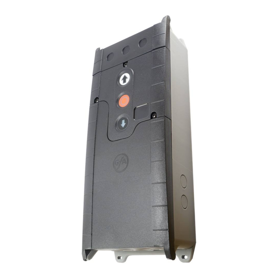
TS970 Блок управления GFA
— Для всех приводов ELEKTROMAT GfA с цифровым
концевыми выключателями DES
— Мощность электрического двигателя
до 3,0 kW
— Напряжение питания 3_230 V/PE;
3_400 V/N/PE; 3_400 V/PE и 1_230 V/N/PE
— Напряжение управления 24 V DC
— Интегрированный защищенный пленкой
нажимной переключатель в крышке корпуса с функциями «открытие – стоп – закрытие»
— Управление с 5 полюсным разъемом
CEE
— В соответствии с указаниями нормы
DIN EN 12453, февраль 2001, подпункт 5.2.9 CEE
— Двухсторонние соединительные кабели
с разъемами
— Длина соединительных кабелей от
3,0 до 15,0 м
— 4 жильный спиральный кабель с разъемом