| Название | Русский | English |
|---|---|---|
| A-S201 Owner’s Manual | — |
[3.2MB] |
| A-S201 Инструкция по эксплуатации |
[3.2MB] |
[3.2MB] |
| CD Player flyer for Hi-Fi Amplifier | — |
[109KB] |
| CD Player flyer for Hi-Fi Amplifier |
[109KB] |
— |
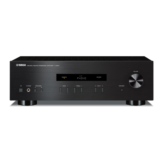
инструкцияYamaha A-S201

Integrated Amplifier
Amplificateur Intégré
OWNER’S MANUAL
MODE D’EMPLOI
BEDIENUNGSANLEITUNG
BRUKSANVISNING
MANUALE DI ISTRUZIONI
MANUAL DE INSTRUCCIONES
GEBRUIKSAANWIJZING
G
Integrated Amplifier
Amplificateur Intégré
OWNER’S MANUAL
MODE D’EMPLOI
BEDIENUNGSANLEITUNG
BRUKSANVISNING
MANUALE DI ISTRUZIONI
MANUAL DE INSTRUCCIONES
GEBRUIKSAANWIJZING
ИНСТРУКЦИЯ ПО ЭКСПЛУАТАЦИИ
G
Посмотреть инструкция для Yamaha A-S201 бесплатно. Руководство относится к категории приемники, 8 человек(а) дали ему среднюю оценку 8.4. Руководство доступно на следующих языках: русский, английский. У вас есть вопрос о Yamaha A-S201 или вам нужна помощь? Задайте свой вопрос здесь

Главная
| Yamaha | |
| A-S201 | A-S201-B | |
| приемник | |
| 4957812542227, 4957812542234 | |
| русский, английский | |
| Руководство пользователя (PDF) |
Аудио
| Выходные звуковые каналы | 2.0 канала |
| Пиковая мощность на канал | 140 W |
| Класс усилителя | — |
| Суммарный коэффициент гармоник (THD) | 0.2 % |
| Сoотношение «сигнал/помеха» (SNR) | 100 dB |
| Выходная мощность RMS на канал (4 Ом) | 140 W |
| Выходная мощность RMS на канал (8 Ом) | 100 W |
| Динамическая мощность на канал (2 Ома) | 180 W |
| Динамическая мощность на канал (4 Ома) | 165 W |
| Динамическая мощность на канал (6 Ом) | 150 W |
| Динамическая мощность на канал (8 Ома) | 125 W |
| Входная чувствительность | 500 mV |
| Диапазон частот | 10 — 100000 Hz |
Порты и интерфейсы
| Тип подключения колонок | Винтовая клемма |
Технические характеристики
| Цвет товара | Черный |
| Предназначение | Дома |
| Технология подключения | Проводная |
| Вкл/Выкл переключатель | Да |
Энергопитание
| Потребляемая мощность (в режим ожидания) | 0.5 W |
Вес и размеры
| Ширина | 435 mm |
| Глубина | 333 mm |
| Высота | 141 mm |
| Вес | 6700 g |
Содержимое упаковки
| Инструкция | Да |
| Пульт дистанционного управления | Да |
показать больше
Не можете найти ответ на свой вопрос в руководстве? Вы можете найти ответ на свой вопрос ниже, в разделе часто задаваемых вопросов о Yamaha A-S201.
Когда звук считается слишком громким?
Уровень звука выше 80 децибел может нанести вред слуху. Уровень звука выше 120 децибел может нанести прямое повреждение слуху. Вероятность повреждения слуха зависит от частоты и продолжительности прослушивания.
Могут ли устройства разных марок подключаться друг к другу при помощи Bluetooth?
Да, Bluetooth — универсальный метод, позволяющий различным устройствам, оснащенным Bluetooth, подключаться друг к другу.
Что такое Bluetooth?
Bluetooth — это способ обмена данными по беспроводной сети между электронными устройствами с помощью радиоволн. Расстояние между двумя устройствами обменивающимися данными в большинстве случаев составляет не более десяти метров.
Что такое HDMI?
HDMI расшифровывается как «интерфейс для мультимедиа высокой четкости». Кабель HDMI используется для передачи аудио- и видеосигналов между устройствами.
Как лучше всего выполнять чистку приемник?
Для удаления отпечатков пальцев лучше всего использовать слегка влажную салфетку для уборки или мягкую чистую ткань. Пыль в труднодоступных местах лучше всего удаляется потоком сжатого воздуха.
Что такое Dolby Atmos?
Dolby Atmos — это технология, которая обеспечивает отражение звука от потолка к месту нахождения слушателя. Это позволяет создать эффект 5.1 при помощи всего лишь одного динамика.
Какой вес Yamaha A-S201?
Yamaha A-S201 имеет вес 6700 g.
Какая высота Yamaha A-S201?
Yamaha A-S201 имеет высоту 141 mm.
Какая ширина Yamaha A-S201?
Yamaha A-S201 имеет ширину 435 mm.
Какая толщина Yamaha A-S201?
Yamaha A-S201 имеет толщину 333 mm.
Инструкция Yamaha A-S201 доступно в русский?
Да, руководствоYamaha A-S201 доступно врусский .
Не нашли свой вопрос? Задайте свой вопрос здесь
-
Contents
-
Table of Contents
-
Troubleshooting
-
Bookmarks
Quick Links
RABL
Integrated Amplifier
OWNER’S MANUAL
MANUAL DE INSTRUCCIONES
Related Manuals for Yamaha A-S201
Summary of Contents for Yamaha A-S201
-
Page 1: Integrated Amplifier
RABL Integrated Amplifier OWNER’S MANUAL MANUAL DE INSTRUCCIONES…
-
Page 2
Note and may cause fire, damage to this unit, and/or personal injury. Yamaha will not be held responsible for any The plug severed from the mains lead must be destroyed, damage resulting from use of this unit with a voltage as a plug with bared flexible cord is hazardous if engaged other than specified. -
Page 3: Table Of Contents
◆ Save power by using the AUTO POWER STANDBY Direct function (see page 11) function (see page 12) ◆ Use the remote control of this unit to operate a Yamaha tuner and/or CD player (see page 6) SUPPLIED ACCESSORIES Please check that you received all of the following parts.
-
Page 4: Controls And Functions
INTRODUCTION CONTROLS AND FUNCTIONS Front panel 5 SLEEP indicator (power) Turns this unit on, or sets it to standby mode. Lights up when the sleep timer is turned on (see page 11). Note 6 Multi-information display This unit consumes a small amount of power even when in Shows information when adjusting or changing standby mode.
-
Page 5
CONTROLS AND FUNCTIONS 0 PHONES jack C TREBLE –/+ Outputs audio to your headphones for private Increases or decreases the high frequency response. listening. Control range: –10 dB to +10 dB D INPUT l / h Note Selects the input source you want to listen to. Press SPEAKERS A/B so that the SP A/B indicators (see page 2) turn off before you connect your headphones to the E VOLUME control… -
Page 6: Rear Panel
CONTROLS AND FUNCTIONS Rear panel 1 Power cable 7 LINE 2 jacks For connecting this unit to an AC wall outlet (see PB (Playback) jacks page 9). Used to connect to audio output jacks of an audio component. 2 GND terminal REC (Recording) jacks Used to connect a turntable (see page 8).
-
Page 7: Remote Control
CONTROLS AND FUNCTIONS Remote control 4 DIMMER Select the brightness level of the front panel display from 3 levels by pressing this button repeatedly. • This setting is retained even if you turn off this unit. • The default setting is the brightest. 5 TREBLE –/+ Increases or decreases the high frequency response.
-
Page 8
■ Yamaha tuner control buttons ■ Yamaha CD player controls The following buttons can be used to control various The following buttons can be used to control a Yamaha functions of a Yamaha tuner. CD player. D TUNING jj / ii E Yamaha CD player control buttons Selects the tuning frequency. -
Page 9: Using The Remote Control
CONTROLS AND FUNCTIONS Using the remote control ■ Installing batteries ■ Operation range Point the remote control at the remote control sensor on this unit and remain within the operating range shown below. Approximately AA, R6, UM-3 batteries Remote control ■…
-
Page 10: Preparation
PREPARATION CONNECTIONS Connecting speakers and source components Make sure to connect L (left) to L, R (right) to R, “+” to “+” and “–” to “–”. If the connections are faulty, no sound will be heard from the speakers, and if the polarity of the speaker connections is incorrect, the sound will be unnatural and lack bass.
-
Page 11: Connecting Power Cable
CONNECTIONS ■ REC jacks ■ Bi-wire connection • The REC jacks output audio signals of the currently Bi-wire connection separates the woofer from the selected input (except when LINE 2 is selected). combined midrange and tweeter section. • Volume level, tone control, balance and Pure Direct A bi-wire compatible speaker has four binding post settings do not affect the REC jacks.
-
Page 12: Playback
BASIC OPERATION PLAYBACK Playing a source Press A (power) to turn on this unit. Press one of the Input selector buttons to select the desired input source. A (power) Press SPEAKERS A and/or SPEAKERS B on the front panel to select desired speaker(s). Input selector buttons Notes…
-
Page 13: Enjoying Pure, High Fidelity Sound (Pure Direct)
PLAYBACK Enjoying pure, high fidelity sound Using the sleep timer (Pure Direct) Use this feature to automatically set this unit to standby mode after a certain amount of time. The sleep timer is The Pure Direct function bypasses unnecessary circuitry useful when you are going to sleep while this unit is in this unit to reduce electrical noise when playing the playing or recording a source.
-
Page 14: Advanced Operation
ADVANCED OPERATION SETTING THE OPTION MENU FOR EACH INPUT SOURCE The Option menu allows you to configure various settings for each input source and recall those settings automatically when an input source is selected. Press one of the Input selector buttons to select the desired input source.
-
Page 15: Additional Information
Refer to the chart below if this unit does not function properly. If the problem you are experiencing is not listed below or if the instructions below do not help, set this unit to standby mode, disconnect the power cable, and then contact the nearest authorized Yamaha dealer or service center. ■ General…
-
Page 16
TROUBLESHOOTING Problem Cause Remedy page The component connected to the LINE 2 Turn on the power of the component. The volume level PB/REC jacks of this unit is turned off. cannot be increased, — or the sound is distorted. This unit has been set to standby mode. Turn on the power of this unit. -
Page 17: Specifications
SPECIFICATIONS AUDIO SECTION • Tone control characteristics BASS • Minimum RMS output power (8 , 40 Hz to 20 kHz, 0.2% THD) Boost/Cut (50 Hz) …………± 10 dB TREBLE [General, Korea, Australia, U.K. and Europe models] Boost/Cut (20 kHz) …………± 10 dB …………….
-
Page 18
Yamaha no se hará responsable de ningún daño debido al Es necesario pegar esta etiqueta a los productos cuya uso de este aparato con una tensión diferente de la cubierta superior pueda estar caliente durante el especificada. -
Page 19: Características De Utilidad
Pure Direct (vea la página 11) STANDBY (vea la página 12) ◆ Utilice el mando a distancia de esta unidad para manejar un sintonizador Yamaha y/o un reproductor de CD (vea la página 6) ACCESORIOS SUMINISTRADOS Verifique que ha recibido los siguientes accesorios.
-
Page 20: Controles Y Funciones
INTRODUCCIÓN CONTROLES Y FUNCIONES Panel frontal 4 Indicadores SP (SPEAKERS) A/B (alimentación) Enciende la unidad o la pone en modo de espera. Se iluminan según el conjunto de altavoces seleccionado. Ambos indicadores se iluminan cuando se han Nota seleccionado los dos conjuntos de altavoces. Esta unidad consume poca alimentación incluso cuando está…
-
Page 21
CONTROLES Y FUNCIONES 0 Toma PHONES C TREBLE –/+ Emite audio a los auriculares para la escucha en Aumenta o reduce la respuesta de alta frecuencia. privado. Rango de control: –10 dB a +10 dB D INPUT l / h Nota Selecciona la fuente de entrada que se va a escuchar. -
Page 22: Panel Trasero
CONTROLES Y FUNCIONES Panel trasero 1 Cable de alimentación 7 Tomas LINE 2 Conecta la unidad a una toma de CA (vea la página 9). Tomas PB (reproducción) Se utilizan para conectar a tomas de salida de audio de 2 Terminal GND un componente de audio.
-
Page 23: Mando A Distancia
CONTROLES Y FUNCIONES Mando a distancia 4 DIMMER Seleccione el nivel de brillo de la pantalla del panel frontal de los 3 niveles pulsando este botón de forma repetida. • Este ajuste se conserva aunque desactive el equipo. • El ajuste por defecto es el más brillante. 5 TREBLE –/+ Aumenta o reduce la respuesta de alta frecuencia.
-
Page 24
Se desplaza hacia delante Guarda la emisora FM/AM actual como presintonizada. Nota Aunque se utilice un reproductor de CD Yamaha, es posible que INFO ciertos componentes y características no estén disponibles. Para Solo para el modelo europeo: más información, consulte el manual de instrucciones de su Cambia la información que se muestra en la pantalla… -
Page 25: Uso Del Mando A Distancia
CONTROLES Y FUNCIONES Uso del mando a distancia ■ Instalación de las pilas ■ Rango operativo Señale con el mando a distancia al sensor del mando a distancia de la unidad y permanezca dentro del rango de funcionamiento mostrado abajo. Aproximadamente Pilas AA, R6, UM-3 Mando a distancia…
-
Page 26: Preparación
PREPARACIÓN CONEXIONES Conexión de los altavoces y los componentes fuente Asegúrese de conectar L (izquierda) a L, R (derecha) a R, “+” a “+” y “–” a “–”. Si las conexiones son incorrectas, no obtendrá sonido en los altavoces. Si la polaridad de las conexiones de los altavoces es incorrecta, el sonido no será natural y notará…
-
Page 27: Conexión Del Cable De Alimentación
CONEXIONES ■ Tomas REC ■ Conexión de doble cable • Las señales de audio de salida de las tomas REC de la La conexión de doble cable separa el altavoz para graves del rango medio combinado y la sección de agudos. unidad seleccionada actualmente (salvo cuando esté…
-
Page 28: Manejo Básico
MANEJO BÁSICO REPRODUCCIÓN Reproducción de una fuente Pulse A (alimentación) para encender la unidad. Pulse uno de los botones de selección de entrada para seleccionar la fuente de entrada A (alimentación) deseada. Botones de Pulse SPEAKERS A y/o SPEAKERS B en el selección de entrada panel frontal para seleccionar el/los altavoz/…
-
Page 29: Disfrute Del Sonido Puro, De Alta Fidelidad (Pure Direct)
REPRODUCCIÓN Disfrute del sonido puro, de alta Uso del temporizador de espera fidelidad (Pure Direct) Utilice esta característica para ajustar automáticamente la unidad al modo de espera una vez transcurrido un tiempo La función Pure Direct omite el circuito innecesario en definido.
-
Page 30: Manejo Avanzado
MANEJO AVANZADO AJUSTE DEL MENÚ OPTION PARA CADA FUENTE DE ENTRADA El menú Option permite configurar varios ajustes para cada fuente de entrada y recuperarlos automáticamente al seleccionar una fuente de entrada. Pulse uno de los botones de selección de entrada para seleccionar la fuente de entrada deseada.
-
Page 31: Información Adicional
Consulte el siguiente cuadro cuando el aparato no funcione bien. Si el problema surgido no aparece en la siguiente lista o las instrucciones no le ayudan, ponga la unidad en modo de espera, desconecte el cable de alimentación y consulte con el centro de servicio o el distribuidor Yamaha autorizado más cercano. ■ Generales…
-
Page 32
SOLUCIÓN DE PROBLEMAS Vea la Problema Causa Remedio página El componente conectado a las tomas Encienda el componente. El nivel del volumen LINE 2 PB/REC de esta unidad está no se puede — apagado. aumentar o se distorsiona el sonido. Esta unidad se ha ajustado al modo en Encienda esta unidad. -
Page 33: Especificaciones
ESPECIFICACIONES SECCIÓN DE AUDIO • Características de control de tono BASS • Potencia de salida RMS mínima (8 , 40 Hz a 20 kHz, 0,2% THD) Potenciador/corte (50 kHz) ………. ± 10 dB TREBLE [Modelos General, para Corea, Australia, RU y Europa] Potenciador/corte (20 kHz) ……….
-
Page 34
© 2013 Yamaha Corporation Printed in Malaysia ZN13350…
G
G
Integrated Amplifier
Integrated Amplifier
Amplificateur Intégré
Amplificateur Intégré
OWNER’S MANUAL
OWNER’S MANUAL
MODE D’EMPLOI
MODE D’EMPLOI
BEDIENUNGSANLEITUNG
BEDIENUNGSANLEITUNG
BRUKSANVISNING
BRUKSANVISNING
MANUALE DI ISTRUZIONI
MANUALE DI ISTRUZIONI
MANUAL DE INSTRUCCIONES
MANUAL DE INSTRUCCIONES
GEBRUIKSAANWIJZING
GEBRUIKSAANWIJZING
ИНСТРУКЦИЯ ПО ЭКСПЛУАТАЦИИ
© 2013 Yamaha Corporation
Printed in Malaysia ZH10680
CAUTION: READ THIS BEFORE OPERATING YOUR UNIT.
CAUTION: READ THIS BEFORE OPERATING YOUR UNIT.
1 To assure the finest performance, please read this manual
17 Before moving this unit, press A (power) to set this unit
carefully. Keep it in a safe place for future reference.
to standby mode, and then disconnect the AC power plug
2 Install this sound system in a well ventilated, cool, dry,
from the AC wall outlet.
clean place — away from direct sunlight, heat sources,
18 Condensation will form when the surrounding
vibration, dust, moisture, and/or cold. For proper
temperature changes suddenly. Disconnect the power
ventilation, allow the following minimum clearances
cable from the outlet, then leave this unit alone.
around this unit.
19 When using this unit for a long time, this unit may
Top: 30 cm
become warm. Turn the power off, then leave this unit
Rear: 20 cm
alone for cooling.
Sides: 20 cm
20 Install this unit near the AC wall outlet and where the AC
3 Locate this unit away from other electrical appliances,
power plug can be reached easily.
motors, or transformers to avoid humming sounds.
21 The batteries shall not be exposed to excessive heat such
4 Do not expose this unit to sudden temperature changes
as sunshine, fire or the like.
from cold to hot, and do not locate this unit in an
22 Excessive sound pressure from earphones and
environment with high humidity (i.e. a room with a
headphones can cause hearing loss.
humidifier) to prevent condensation inside this unit,
which may cause an electrical shock, fire, damage to this
This unit is not disconnected from the AC power source as long as
unit, and/or personal injury.
it is connected to the AC wall outlet, even if this unit itself is turned
5 Avoid installing this unit where foreign object may fall
off by A. This state is called the standby mode. In this state, this
onto this unit and/or this unit may be exposed to liquid
unit is designed to consume a very small quantity of power.
dripping or splashing. On the top of this unit, do not
place:
WARNING
– Other components, as they may cause damage and/or
TO REDUCE THE RISK OF FIRE OR ELECTRIC SHOCK, DO
discoloration on the surface of this unit.
NOT EXPOSE THIS UNIT TO RAIN OR MOISTURE.
– Burning objects (i.e. candles), as they may cause fire,
damage to this unit, and/or personal injury.
– Containers with liquid in them, as they may fall and
liquid may cause electrical shock to the user and/or
damage to this unit.
6 Do not cover this unit with a newspaper, tablecloth,
curtain, etc. in order not to obstruct heat radiation. If the
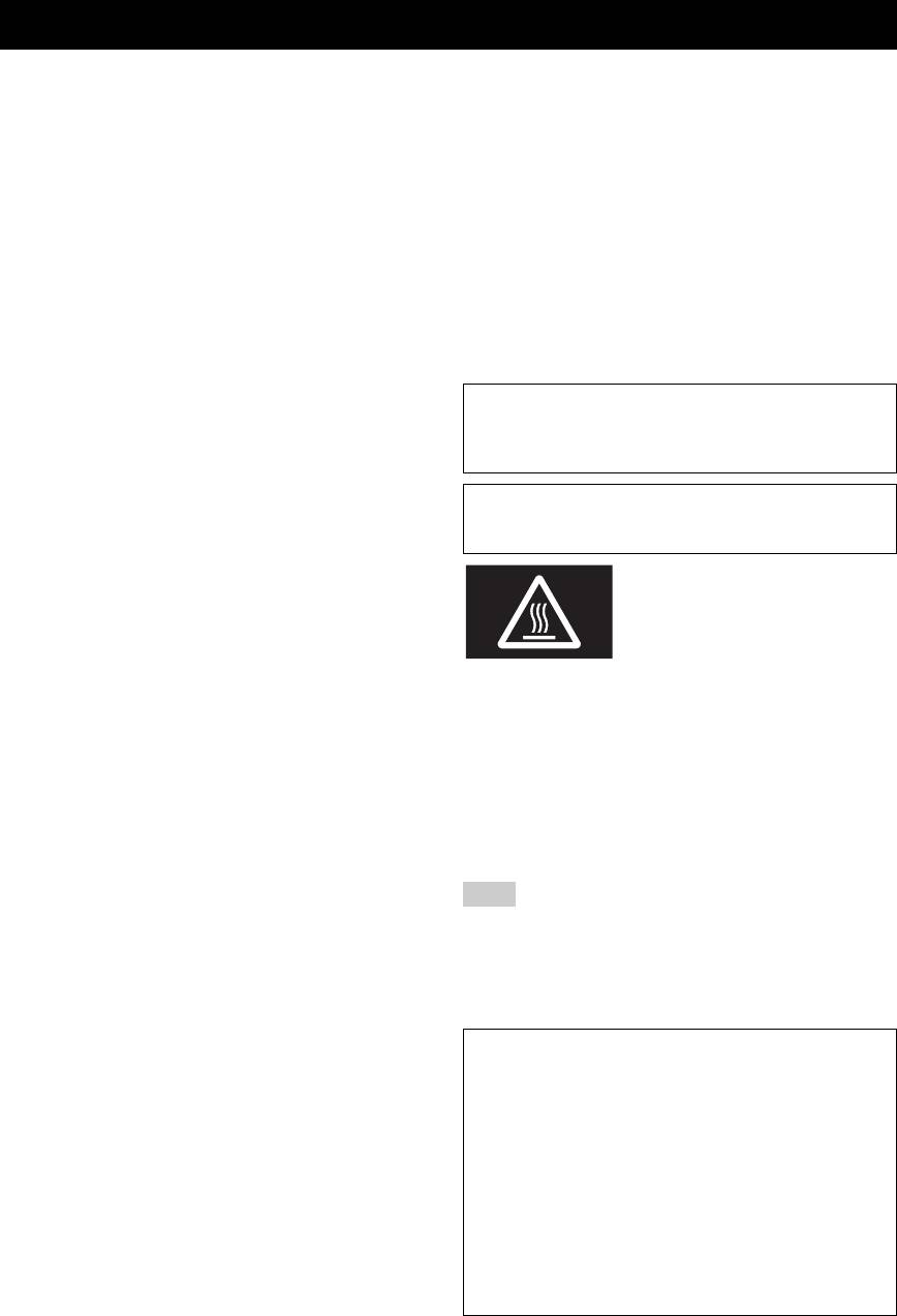
This label is required to be attached to a product of which
temperature inside this unit rises, it may cause fire,
the temperature of the top cover may be hot during
damage to this unit, and/or personal injury.
operation.
7 Do not plug in this unit to an AC wall outlet until all
connections are complete.
■ For U.K. customers
8 Do not operate this unit upside-down. It may overheat,
If the socket outlets in the home are not suitable for the
possibly causing damage.
plug supplied with this appliance, it should be cut off and
9 Do not use force on switches, knobs and/or cords.
an appropriate 3 pin plug fitted. For details, refer to the
10 When disconnecting the power cable from the AC wall
instructions described below.
outlet, grasp the plug; do not pull the cable.
11 Do not clean this unit with chemical solvents; this might
Note
damage the finish. Use a clean, dry cloth.
12 Only voltage specified on this unit must be used. Using
The plug severed from the mains lead must be destroyed,
this unit with a higher voltage than specified is dangerous
as a plug with bared flexible cord is hazardous if engaged
and may cause fire, damage to this unit, and/or personal
in a live socket outlet.
injury. Yamaha will not be held responsible for any
damage resulting from use of this unit with a voltage
■ Special Instructions for U.K. Model
other than specified.
13 To prevent damage by lightning, keep the power cable
IMPORTANT
and outdoor antennas disconnected from an AC wall
THE WIRES IN MAINS LEAD ARE COLOURED IN
outlet or this unit during a lightning storm.
ACCORDANCE WITH THE FOLLOWING CODE:
14 Do not attempt to modify or fix this unit. Contact
Blue: NEUTRAL
qualified Yamaha service personnel when any service is
Brown: LIVE
needed. The cabinet should never be opened for any
As the colours of the wires in the mains lead of this apparatus may
reasons.
not correspond with the coloured markings identifying the
15 When not planning to use this unit for long periods of
terminals in your plug, proceed as follows:
time (i.e. vacation), disconnect the AC power plug from
The wire which is coloured BLUE must be connected to the
terminal which is marked with the letter N or coloured BLACK.
the AC wall outlet.
The wire which is coloured BROWN must be connected to the
16 Be sure to read the “TROUBLESHOOTING” section on
terminal which is marked with the letter L or coloured RED.
common operating errors before concluding that this unit
Make sure that neither core is connected to the earth terminal of the
is faulty.
three pin plug.
i En
CONTENTS
INTRODUCTION
BASIC OPERATION
USEFUL FEATURES ……………….…………..……….. 1
PLAYBACK .……….…………..…………..……….………10
SUPPLIED ACCESSORIES …………………….…….. 1
Playing a source…….………..………………………………. 10
CONTROLS AND FUNCTIONS …………..……….. 2
Enjoying pure, high fidelity sound (Pure Direct) …. 11
Front panel…….………………..…………………………..…… 2
Using the sleep timer……..……..…………………………. 11
Rear panel..………………..……………………………………..4
Remote control……….……..………………………………….. 5
Using the remote control …..…………………………..…… 7
ADVANCED OPERATION
PREPARATIONINTRODUCTION
SETTING THE OPTION MENU FOR EACH
PREPARATION
INPUT SOURCE…………..…………..……….………12
Option menu items…………………..………………………. 12
CONNECTIONS ……………..……….…………..……….. 8
Connecting speakers and source components….…….. 8
Connecting power cable ………………………………..…… 9
ADDITIONAL INFORMATION
TROUBLESHOOTING ………………..……….………13
SPECIFICATIONS………..………….…………..………15
■ About this manual
OPERATION
• y indicates a tip for your operation.
BASIC
• The instructions in this manual describe the operation of this unit with the supplied remote control. You can also use the buttons or
knobs on the front panel if they have the same or similar names as those on the remote control.
USEFUL FEATURES
This unit allows you to:
◆ Enjoy pure, high fidelity sound by using the Pure
◆ Save power by using the AUTO POWER STANDBY
OPERATION
ADVANCED
Direct function (see page 11)
function (see page 12)
◆ Use the remote control of this unit to operate a Yamaha
tuner and/or CD player (see page 6)
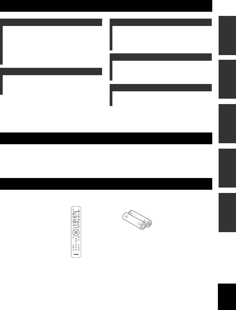
SUPPLIED ACCESSORIES
Please check that you received all of the following parts.
INFORMATION
ADDITIONAL
Remote control Batteries (x2)
(AA, R6, UM-3)
English
1 En
INTRODUCTION
CONTROLS AND FUNCTIONS
Front panel
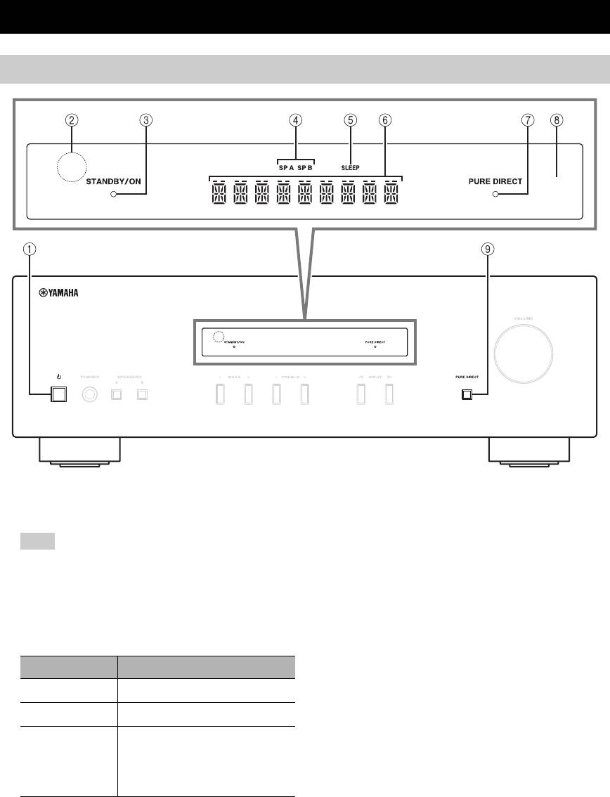
1 A (power)
5 SLEEP indicator
Turns this unit on, or sets it to standby mode.
Lights up when the sleep timer is turned on (see
page 11).
Note
6 Multi-information display
This unit consumes a small amount of power even when in
Shows information when adjusting or changing
standby mode.
settings.
2 Remote control sensor
7 PURE DIRECT indicator
Receives infrared signals from the remote control.
Lights up when the Pure Direct function is on.
3 STANDBY/ON indicator
8 Front panel display
Indicator Status
Shows information about the operational status of this
unit.
Brightly lit
The power of this unit is “on”.
9 PURE DIRECT button
Dimly lit
This unit is in “standby” mode.
Reproduces any input source in the purest sound
Off
The power of this unit is “off”.
possible. (see page 11).
To turn off this unit, disconnect
the power cable from an AC
wall outlet.
4 SP (SPEAKERS) A/B indicators
Light up according to the set of speakers selected.
Both indicators light up when both sets of speakers are
selected.
2 En
CONTROLS AND FUNCTIONS
INTRODUCTION
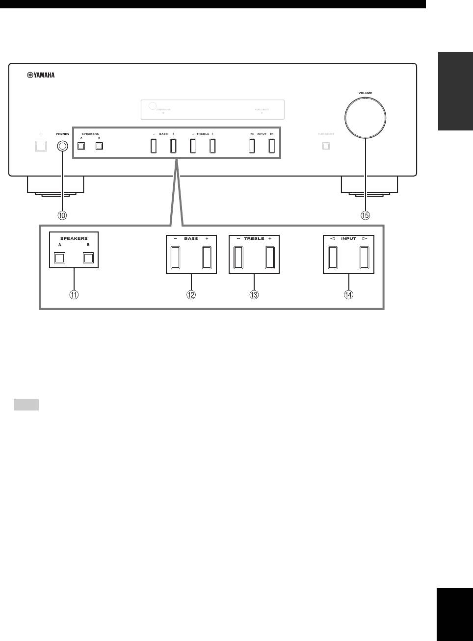
0 PHONES jack
C TREBLE –/+
Outputs audio to your headphones for private
Increases or decreases the high frequency response.
listening.
Control range: –10 dB to +10 dB
Note
D INPUT l / h
Press SPEAKERS A/B so that the SP A/B indicators (see
Selects the input source you want to listen to.
page 2) turn off before you connect your headphones to the
E VOLUME control
PHONES jack.
Increases or decreases the sound output level.
A SPEAKERS A/B
Turns on or off the speaker set connected to the
SPEAKERS A and/or SPEAKERS B terminals on the
rear panel each time the corresponding button is
pressed (see page
10
).
B BASS –/+
Increases or decreases the low frequency response.
Control range: –10 dB to +10 dB
English
3 En
CONTROLS AND FUNCTIONS
Rear panel
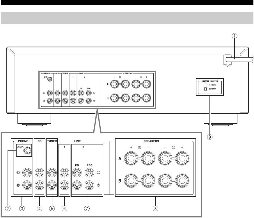
1 Power cable
7 LINE 2 jacks
For connecting this unit to an AC wall outlet (see
PB (Playback) jacks
page 9).
Used to connect to audio output jacks of an audio
component.
2 GND terminal
REC (Recording) jacks
Used to connect a turntable (see page  .
.
Used to connect to audio input jacks of an audio
3 PHONO jacks
component.
Used to connect a turntable (see page .
8 SPEAKERS terminals
4 CD jacks
Used to connect speakers (see page 8).
Used to connect a CD player (see page 8).
9 VOLTAGE SELECTOR (Only for General
5 TUNER jacks
model)
Used to connect a tuner (see page 8).
6 LINE 1 jacks
Used to connect audio components (see page 8).
4 En
CONTROLS AND FUNCTIONS
Remote control
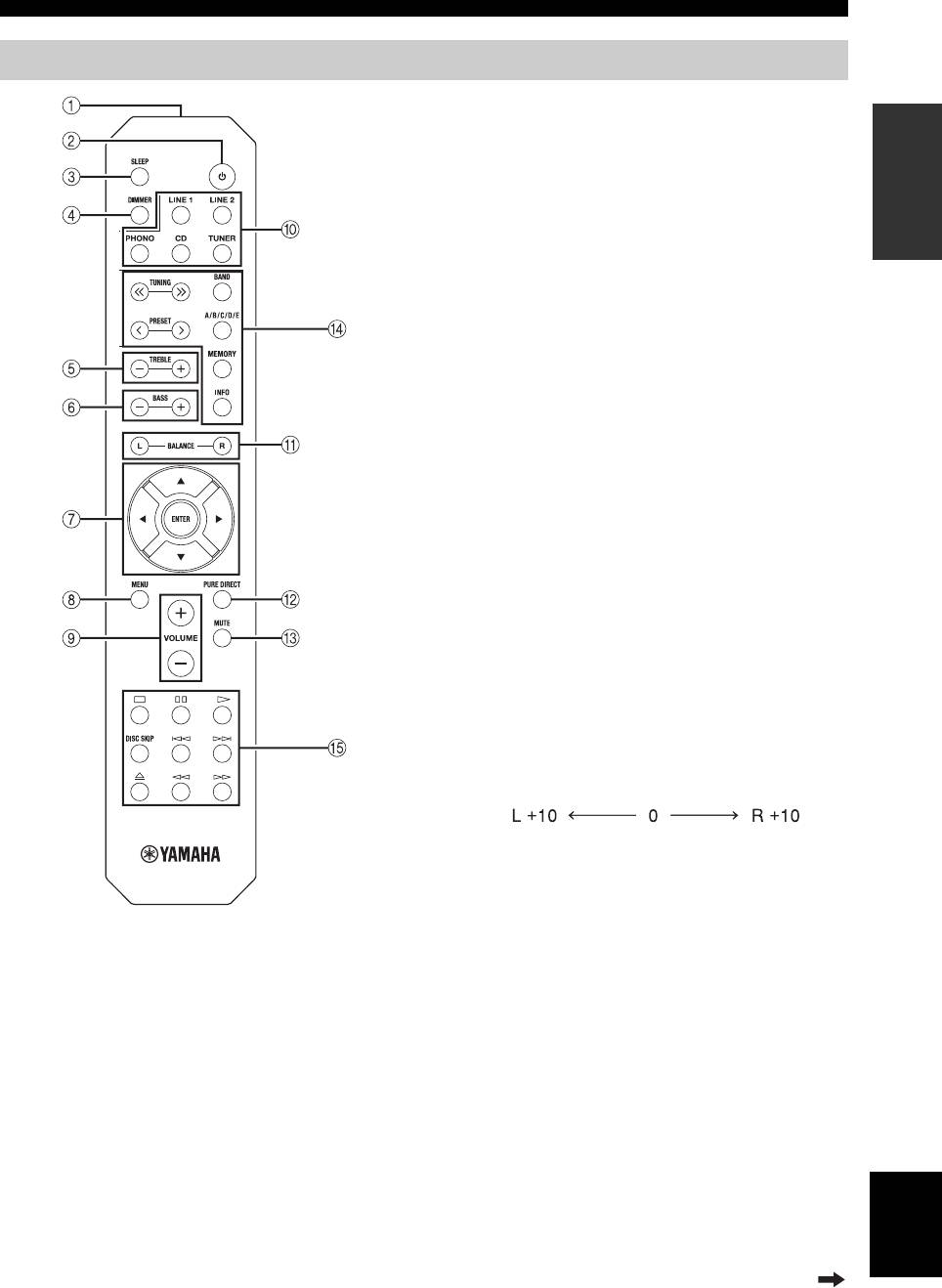
4 DIMMER
INTRODUCTION
Select the brightness level of the front panel display
from 3 levels by pressing this button repeatedly.
y
• This setting is retained even if you turn off this unit.
• The default setting is the brightest.
5 TREBLE –/+
Increases or decreases the high frequency response.
Control range: –10 dB to +10 dB
6 BASS –/+
Increases or decreases the low frequency response.
Control range: –10 dB to +10 dB
7 B / C / D / E / ENTER
Selects and confirms items in the Option menu (see
page 12).
8 MENU
Turns the Option menu on and off (see page 12).
9 VOLUME +/–
Increases or decreases the sound output level.
0 Input selector buttons
Select the input source you want to listen to.
y
The input source names correspond to the names of the
connection jacks on the rear panel.
A BALANCE L/R
Adjusts the sound output balance of the left and right
speakers to compensate for sound imbalances.
Control range:
(+20 dB) (center) (+20 dB)
The opposite side of
The opposite side of
channel is muted.
channel is muted.
B PURE DIRECT button
■ Common controls
Reproduces any input source in the purest sound
The following parts and controls can be used no matter
possible (see page 11).
which input source is selected.
C MUTE
1 Infrared signal transmitter
Mutes the sound output. Press again to restore the
Sends infrared signals.
sound output to the previous volume level.
2
A (power)
Turns this unit on, or sets it to standby mode.
3 SLEEP
Sets the sleep timer (see page 11).
English
Continued to the next page.
5 En

CONTROLS AND FUNCTIONS
■ Yamaha tuner control buttons
■ Yamaha CD player controls
The following buttons can be used to control various
The following buttons can be used to control a Yamaha
functions of a Yamaha tuner.
CD player.
D TUNING jj / ii
E Yamaha CD player control buttons
Selects the tuning frequency.
s Stops playback
e Pauses playback
A/B/C/D/E, PRESET j / i
p Starts playback
Selects a preset FM/AM station.
DISC SKIP Skips to the next disc in a CD changer
A/B/C/D/E: Selects the preset group from A to E.
b Skips backward
PRESET j / i: Selects the preset number.
a Skips forward
BAND
Ejects the disc
Selects the reception band (FM/AM).
w Rewinds playback
f Fast-forwards playback
MEMORY
Stores the current FM/AM station as a preset.
Note
INFO
Even when using a Yamaha CD player, certain components and
Only for Europe model:
features may not be available. Refer to your component’s owner’s
manual for more information.
Switches information shown on the front panel
display.
Note
Even when using a Yamaha tuner, certain components and
features may not be available. Refer to your component’s owner’s
manual for more information.
6 En
CONTROLS AND FUNCTIONS
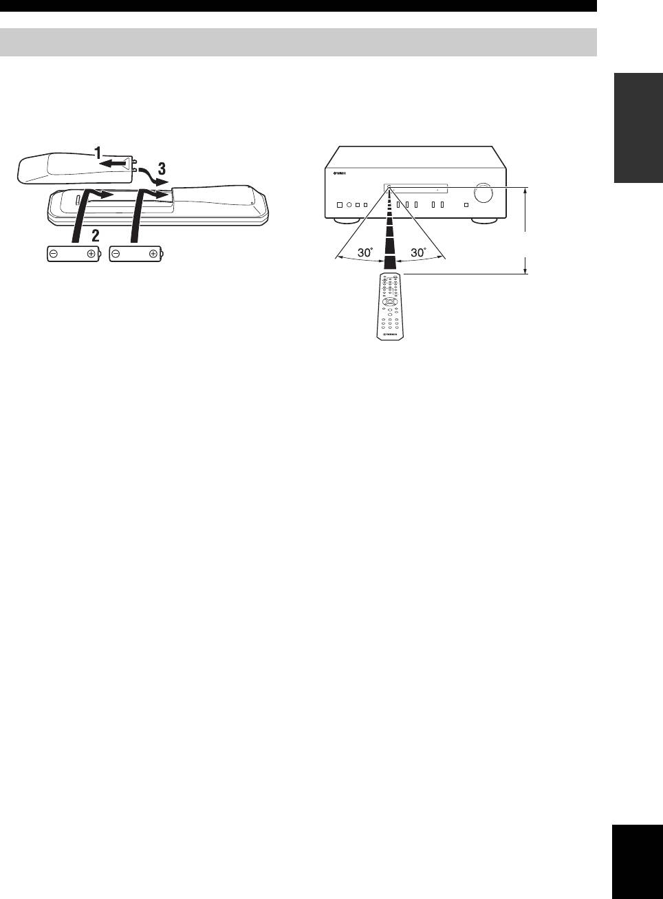
Using the remote control
■ Installing batteries ■ Operation range
INTRODUCTION
Point the remote control at the remote control sensor on
this unit and remain within the operating range shown
below.
Approximately
6 m
AA, R6, UM-3 batteries
Remote control
■ Notes on remote control and batteries
• The area between the remote control and this unit must be clear of large obstacles.
• Be careful not to spill water or other liquids on the remote control.
• Be careful not to drop the remote control.
• Do not leave or store the remote control in the following conditions:
– places of high humidity, such as near a bathroom
– places of high temperatures, such as near a heater or stove
– places of extremely low temperatures
– dusty places
• Change all batteries if you notice the operation range of the remote control narrows.
• If the batteries run out, immediately remove them from the remote control to prevent an explosion or acid leak.
• If you find leaking batteries, discard the batteries immediately, taking care not to touch the leaked material. If the leaked material
comes into contact with your skin or gets into your eyes or mouth, rinse it away immediately and consult a doctor. Clean the battery
compartment thoroughly before installing new batteries.
• Do not use old batteries together with new ones. This may shorten the life of the new batteries or cause old batteries to leak.
• Do not use different types of batteries (such as alkaline and manganese batteries) together. Batteries that look the same may have a
different specification.
• Before inserting new batteries, wipe the battery compartment clean.
• Dispose of batteries according to your regional regulations.
• Keep the batteries in a location out of reach of children.
Batteries can be dangerous if a child were to put in his or her mouth.
• If you plan not to use this unit for a long period of time, remove the batteries from this unit. Otherwise, the batteries will wear out,
possibly resulting in a leakage of battery liquid that may damage this unit.
English
7 En