-
Contents
-
Table of Contents
-
Troubleshooting
-
Bookmarks
Quick Links
VIESMANN
Installation and service instructions
for contractors
Vitotronic 200
Type KO1B, KO2B
Weather-compensated, digital boiler control unit
For applicability, see the last page
VITOTRONIC 200
Please keep safe.
5458 905 GB
12/2014
Related Manuals for Viessmann VITOTRONIC 200
Summary of Contents for Viessmann VITOTRONIC 200
-
Page 1
VIESMANN Installation and service instructions for contractors Vitotronic 200 Type KO1B, KO2B Weather-compensated, digital boiler control unit For applicability, see the last page VITOTRONIC 200 Please keep safe. 5458 905 GB 12/2014… -
Page 2
■ Statutory regulations for the protection of the envi- For replacements, use only original spare parts ronment supplied or approved by Viessmann. ■ Codes of Practice of the relevant trade associations All current safety regulations as defined by DIN, EN, Safety instructions for operating the system ■… -
Page 3
Safety instructions Safety instructions (cont.) If you smell flue gas Danger Flue gas can lead to life threatening poisoning. ■ Shut down the heating system. ■ Ventilate the installation site. ■ Close doors to living spaces to prevent flue gases from spreading. Flue systems and combustion air Ensure that flue systems are clear and cannot be sealed, for instance due to accumulation of conden-… -
Page 4: Table Of Contents
Changing the slope and level …………. 30 ■ Connecting the control unit to the LON ……….31 Example of a single boiler system with Vitotronic 200-H and ■ Vitocom 200 ………………31 Carrying out a LON subscriber check ……….32 ■…
-
Page 5
Index Index 6. Coding level 1 «General» group ………………34 Coding ………………..34 ■ «Boiler» group ………………35 Coding ………………..35 ■ «DHW» group ………………36 Coding ………………..36 ■ «Solar» group ………………36 «Heating circuit 1», «Heating circuit 2», «Heating circuit 3» group … 37 Coding ……………….. -
Page 6
Index Index (cont.) 12. Components Coding card ………………. 84 Fuse ………………….. 84 Sensors ………………..84 Boiler water, cylinder, buffer, flow and room temperature sensors ..84 ■ Outside temperature sensor …………… 85 ■ Flue gas temperature sensor, part no. 7452 531 …….. 85 ■… -
Page 7
Product information The Vitotronic 200, type KO1B and KO2B for weather-compensated operation are designed for use in single boiler systems. One heating circuit without mixer and 2 heating circuits with mixer can be controlled. -
Page 8: Installing The Control Unit Base
Vitotronic control unit installation Installing the control unit base Boiler installation instructions Fitting the top of the control unit for type KO1B Please note ‘Live’ voltage can lead to PCB damage. Switch OFF the power supply at the control unit. Fig.1…
-
Page 9: Opening The Control Unit
Vitotronic control unit installation Opening the control unit Type KO1B Fig.2…
-
Page 10: Type Ko2B
Vitotronic control unit installation Opening the control unit (cont.) Type KO2B Fig.3 Plugging in the coding card Only insert the boiler coding card supplied with the boiler pack (see table on page 84). Fig.4 Insert the boiler coding card through the opening in the cover into slot «X7».
-
Page 11: Type Ko1B
Vitotronic control unit installation Adjusting the high limit safety cut-out (if… (cont.) When adjusting the safety cut-out to 100 °C, never set the temperature controller higher than 75 °C. Type KO1B °C Fig.5 Slotted screw for EGO products Slotted screw for JUMO products…
-
Page 12: Type Ko2B
Vitotronic control unit installation Adjusting the high limit safety cut-out (if… (cont.) °C Fig.6 Slotted screw for Rathgeber products Slotted screw for JUMO products Type KO2B Fig.7…
-
Page 13: Adjusting The Temperature Controller (If Required)
Vitotronic control unit installation Adjusting the high limit safety cut-out (if… (cont.) °C Fig.8 Slotted screw for EGO products Slotted screw for JUMO products Adjusting the temperature controller (if required) The temperature controller is set to 75 °C in the deliv- 1.
-
Page 14: Type Ko1B
Vitotronic control unit installation Adjusting the temperature controller (if… (cont.) Type KO1B Fig.9 Type KO2B Fig.10…
-
Page 15: Overview Of Electrical Connections
Electrical connections Overview of electrical connections Danger Please note Incorrect wiring can lead to serious injury from Electronic assemblies can be damaged by static electrical current and result in appliance dam- loads. age. Prior to commencing work, touch an earthed ■…
-
Page 16: Inserting Cables/Leads And Applying Strain Relief
Electrical connections Overview of electrical connections (cont.) Plug Component Burner Power supply for accessories External burner start, stage 1 Inserting cables/leads and applying strain relief Blank off unnecessary apertures in the lower part of the control unit with cable grommets (not cut out). Cable with cast-on cable entry Cable without cast-on cable entry Connecting the sensors…
-
Page 17: Connecting The Pumps
Electrical connections Connecting the sensors (cont.) Wireless outside temperature sensor «Wireless base station» installation and service instructions Connecting the pumps Available pump connections Connections on the 230 V~ PCB Plug Component Heating circuit pump for heating circuit HC1/A1 sÖ Circulation pump for cylinder heating DHW circulation pump Pumps 230 V~ Pumps with power consumption greater than 2 A…
-
Page 18: Pumps 400 V
Electrical connections Connecting the pumps (cont.) Pumps 400 V~ For switching the contactor L1 L2 L3 N PE Rated current 4(2) A~ Recommended connecting H05VV-F3G 0.75 mm cable H05RN-F3G 0.75 mm Fig.14 Pump To the control unit Contactor External burner start Please note If the contact is closed, burner stage 1 is started and ‘Live’ contacts lead to short circuits or phase fail-…
-
Page 19: External Demand Via Switching Contact
Electrical connections External demand via switching contact Connection options: ■ Plug ■ EA1 extension (accessories, see page 91) Connection Please note ‘Live’ contacts lead to short circuits or phase fail- ure. The external connection must be potential- free. Plug EA1 extension Floating contact EA1 extension Floating contact…
-
Page 20: External Demand Via 0
Electrical connections External demand via 0 10 V input – (cont.) ≙ No default set boiler water temperature – ≙ Set value 10 °C ≙ 10 V Set value 100 °C [{{] 0-10V fÖ Ö Fig.17 External blocking via switching contact Connection options: Please note ■…
-
Page 21: Codes
To the control unit To the burner Burner without plug Install the mating plug from Viessmann or from the burner manufacturer; connect the burner cable. Extending two-stage/modulating burners, part no. 7404 960 The function extension is supplied with the boiler.
-
Page 22: Connecting An Atmospheric Burner
Electrical connections Extending two-stage/modulating burners, part… (cont.) Max. power consumption ■ Two-stage: 1 (0.5) A ■ Modulating: 0.1 (0.05) A Terminal codes T6, T7, T8 Control chain «Burner stage 2», via two- point controller Control chain «modulation controller», via three-point controller From the burner Modulating burner close Modulating burner open/stage 2 ON…
-
Page 23: Extension, Two-Stage Burner, Part No. 7827 417
Electrical connections Connecting an atmospheric burner (cont.) Terminal codes T1, T2 Control chain Burner fault Hours run meter Fig.20 To the control unit To the burner control unit Extension, two-stage burner, part no. 7827 417 The function extension is supplied with the boiler. BN BU BU BK BN Fig.21…
-
Page 24: Power Supply
Electrical connections Connecting an atmospheric burner (cont.) Colour coding to IEC 60757 BK Black BN Brown BU Blue Power supply Isolators for non-earthed conductors Danger ■ Install an isolator in the power cable to provide Incorrectly executed electrical installations can omnipolar separation from the mains for all active result in injuries from electrical current and in conductors, corresponding to overvoltage category…
-
Page 25: Power Supply For Several Accessories
Electrical connections Power supply (cont.) Power supply for several accessories Power supply for all accessories via the control unit Fig.22 Some accessories with direct power supply Fig.23 Boiler control unit EA1 extension and/or solar control module, Extension kit, mixer M2 type SM1 (internal fuse protection 2 A) (internal fuse protection 2 A)
-
Page 26: Control Unit Power Supply
Electrical connections Power supply (cont.) Control unit power supply 1. Check whether the power cable to the control unit has appropriate fuse protection. 2. Connect the power cable in the wiring chamber. 3. Insert plug into the control unit. fÖ Fig.24 Mains voltage 230 V~ Fuse (max.
-
Page 27: Testing The High Limit Safety Cut-Out
Commissioning Testing the high limit safety cut-out Type KO1B 1. Hold down the «test» key (position » «) until the 2. Release the «test» key. burner shuts down: The temperature controller » » is bridged. When 3. Wait until the boiler water temperature has dropped the boiler water temperature reaches the safety approx.
-
Page 28: Setting The Date And Time
Commissioning Setting the date and time The time and date need to be reset during commis- sioning and after a prolonged time out of use. Setting time and date Continue with Fig.27 Adjusting coding addresses The control unit must be adjusted subject to the sys- tem equipment level.
-
Page 29: Set Room Temperature, Adjusting
Commissioning Adjusting heating curves (cont.) Slope -5 -10 -15 -20 Outside temperature in °C Fig. 28 Example for outside temperature 14 °C − Underfloor heating system, slope 0.2 to 0.8 Low temperature heating system, slope 0.8 to 1.6 Heating systems with a boiler water temperature in excess of 75 °C, slope greater than 1.6 Set room temperature, adjusting Individually adjustable for each heating circuit.
-
Page 30: Changing The Slope And Level
Commissioning Adjusting heating curves (cont.) 3. Select heating circuit. 4. «Set room temperature» 2. «Heating» 5. Set the required value. 3. Select heating circuit. Reduced set room temperature 4. «Set reduced room temp» 5. Set the required value. 14 °C 3 °C B -20 Fig.
-
Page 31: Connecting The Control Unit To The Lon
Installation and service instructions ■ The data transfer via LON can take several minutes. Vitotronic 200-H Example of a single boiler system with Vitotronic 200-H and Vitocom 200 Fig.33 Boiler control unit Vitotronic 200-H Vitocom All codes detailed in the table are listed in the «General» group.
-
Page 32: Carrying Out A Lon Subscriber Check
Commissioning Connecting the control unit to the LON (cont.) Carrying out a LON subscriber check The subscriber check is used to test communication 4. Select subscriber. with the system devices connected to the fault man- ager. 5. Start the subscriber check with «OK». Preconditions: Note ■…
-
Page 33: Calling Up Coding Levels
Coding levels Calling up coding levels The display of the codes is specified by the heating 2. «Coding level 1» ■ system configuration. ■ The codes are divided into groups: 3. Select group. – «General» – «Boiler» 4. Select coding address. «DHW»…
-
Page 34: General» Group
The boiler circuit pump runs on after the burner has stopped. Subscriber no. 77:1 LON subscriber number 77:2 LON subscriber number adjustable from 1 to 99: 77:99 1 = Boiler control unit 90 = Vitotronic 200-H – 98 = Vitogate – 99 = Vitocom…
-
Page 35: Boiler» Group
Coding level 1 «General» group (cont.) Coding in the delivered condition Possible change Detached house/apartment building 7F:1 Detached house 7F:0 Apartment building Holiday program and time program for DHW heating can be set sepa- rately. Lock out controls 8F:0 Operation enabled in standard 8F:1 Operation blocked in standard menu menu and in extended menu.
-
Page 36: Dhw» Group
Coding level 1 «Boiler» group (cont.) Coding in the delivered condition Possible change Service status 24:0 No «Service» indication on the dis- 24:1 «Service» indicator is shown on the play display (the address is automatically set and must be manually reset after a service has been carried out).
-
Page 37: Heating Circuit 1″, «Heating Circuit 2», «Heating Circuit 3» Group
Coding level 1 «Solar» group (cont.) Coding in the delivered condition Possible change Flow rate solar circuit 0F:70 Solar circuit flow rate at the maxi- 0F:1 Flow rate adjustable from 0.1 to mum pump speed 7 l/min. 25.5 l/min; ≙ 0F:255 1 step 0.1 l/min.
-
Page 38
Coding level 1 «Heating circuit 1», «Heating circuit 2», «Heating circuit 3» group (cont.) Parameter address A5:… With heating circuit pump logic function: Heating circuit pump «OFF» > > – > – Coding in the delivered condition Possible change Extended economy function, adjusted outside temperature A6:36 Extended economy mode disa- A6:5… -
Page 39
Coding level 1 «Heating circuit 1», «Heating circuit 2», «Heating circuit 3» group (cont.) Parameter address With heating circuit pump logic function: b5:… Heating circuit pump «OFF» Heating circuit pump «ON» + 5 K < RT + 4 K > actual actual + 4 K… -
Page 40
Coding level 1 «Heating circuit 1», «Heating circuit 2», «Heating circuit 3» group (cont.) Coding in the delivered condition Possible change Party mode time limit F2:8 Time limit for party mode or exter- F2:0 No time limit nal operating program changeover F2:1 Time limit adjustable from 1 to 12 h via pushbutton: 8 h… -
Page 41: Coding
Coding level 2 «General» group Coding Coding in the delivered condition Possible change 00:1 One heating circuit without mixer 00:2 For system schemes, see the follow- A1 (heating circuit 1), without ing table DHW heating 00:10 Value address Description 00: … 1 heating circuit without mixer A1 (heating circuit 1), with DHW heating, is recognised automatically.
-
Page 42
Coding level 2 «General» group (cont.) Coding in the delivered condition Possible change 3b:2 External demand with set minimum boiler water temperature. Setting of set value in coding ad- dress «9b» in this group. 3b:3 External blocking 3b:4 External blocking with fault message 3b:5 Fault message input 3b:6… -
Page 43
77:1 LON subscriber number 77:2 LON subscriber number adjustable from 1 to 99: 77:99 1 = Boiler control unit 90 = Vitotronic 200-H – 98 = Vitogate – 99 = Vitocom 79:1 With LON communication module: 79:0 Control unit is not fault manager. -
Page 44: Boiler» Group
The outside temperature of the temperature. sensor connected to the control 97:2 The control unit sends the outside unit is used internally. temperature to the Vitotronic 200-H. 98:1 Viessmann system number (in 98:1 System number adjustable from 1 to conjunction with monitoring several systems via Vitocom 300).
-
Page 45
Coding level 2 «Boiler» group (cont.) Coding in the delivered condition Possible change ERB80 function (values from 6 to 20 K) 06:74 Electronic maximum limit for boiler 06:20 Maximum limit adjustable from 20 to water temperature set to 74 °C. 127 °C. -
Page 46: Dhw» Group
Coding level 2 «Boiler» group (cont.) Coding in the delivered condition Possible change ≙ 1 step 100 h 23:0 No interval for burner service 23:1 Interval adjustable from 1 to 24 months. 23:24 24:0 No «Service» indication on the dis- 24:1 «Service»…
-
Page 47: Solar» Group
Coding level 2 «DHW» group (cont.) Coding in the delivered condition Possible change 59:0 Cylinder heating: 59:1 Start point adjustable from 1 to 10 K Start point 2.5 K below set value. – Stop point +2.5 K 59:10 5b:0 Do not adjust 5E:0 Circulation pump for cylinder heat- 5E:1…
-
Page 48
Frost protection function for solar 0b:1 Frost protection function for solar cir- circuit switched off cuit switched on (not required with Viessmann heat transfer medium) 0C:1 Delta T monitoring enabled 0C:0 Delta T monitoring disabled No flow rate captured in the solar circuit, or flow rate too low. -
Page 49
Coding level 2 «Solar» group (cont.) Coding in the delivered condition Possible change 10:0 Target temperature control switch- 10:1 Target temperature control switched ed off (see coding address «11») 11:50 Set solar DHW temperature 50 °C 11:10 The set solar DHW temperature is Target temperature control adjustable from 10 to 90 °C. -
Page 50: Heating Circuit 1″, «Heating Circuit 2», «Heating Circuit 3» Group
Coding level 2 «Solar» group (cont.) Coding in the delivered condition Possible change 27:15 Cyclical heating time 15 min 27:5 The cyclical heating time is adjusta- Once the DHW cylinder with priori- ble from 5 to 60 min. ty is heated up, the DHW cylinder 27:60 without priority is heated for a max- imum duration equal to the set cy-…
-
Page 51
Coding level 2 «Heating circuit 1», «Heating circuit 2», «Heating circuit 3» group (cont.) Parameter Heating circuit pump Address A3:… «On» «Off» 4 °C 2 °C – – – 3 °C 1 °C – – – 2 °C 0 °C –… -
Page 52
Coding level 2 «Heating circuit 1», «Heating circuit 2», «Heating circuit 3» group (cont.) Coding in the delivered condition Possible change A6:36 Extended economy mode disa- A6:5 Extended economy mode enabled, bled i.e. at a variably adjustable value be- A6:35 tween 5 and 35 °C plus 1 °C, the burner and heating circuit pump will stop and the mixer will close. -
Page 53
Coding level 2 «Heating circuit 1», «Heating circuit 2», «Heating circuit 3» group (cont.) Parameter address With heating circuit pump logic function: b5:… Heating circuit pump «OFF» Heating circuit pump «ON» + 3 K < RT + 2 K > actual actual + 2 K… -
Page 54
Coding level 2 «Heating circuit 1», «Heating circuit 2», «Heating circuit 3» group (cont.) Coding in the delivered condition Possible change Set day value adjustable at the re- E1:2 Set day temperature adjustable from mote control from 10 to 30 °C 17 to 37 °C E2:50 With remote control:… -
Page 55: Service Scans Calling Up The Service Menu
Service scans Calling up the service menu Press OK and simultaneously for approx. 4 s. «Service» «Diagnosis» Note «General» «Coding level 2» is only displayed if this level has been enabled: «Heating circuit 1/2/3» Press OK and simultaneously for approx. 4 s. «DHW»…
-
Page 56: Resetting Operating Data
Service scans Resetting operating data Display Explanation «Adjusted outside temp» The adjusted outside temperature is reset to the actual value. «Max. flue gas temp» Max. flue gas temp «Burner» Burner hours run «Burner starts» Burner starts «Fuel consumption» Fuel consumption In conjunction with a solar thermal system: «Diff t monitor»…
-
Page 57: Carrying Out An Actuator Test
Service scans Brief scan (cont.) Software ver- sion, EA1 exten- sion LON subnet address/system LON node address number SNVT config. Software ver- Software version, neuron chip Subscriber no. 0: Auto sion, commun- 1: Tool ic. coproc. Heating circuit HC1 Heating circuit HC2 Heating circuit HC3 Remote control Software ver-…
-
Page 58: Checking The Sensors
Service scans Carrying out an actuator test (cont.) Display Explanation «DHW circ pump» Actuator at output «Central fault message» Central fault message facility at output of EA1 exten- sion. «Htg circ pump HC2» Actuator at output sÖ of mixer extension kit (heating circuit with mixer M2) «Mixer HC2″…
-
Page 59: Calling Up Acknowledged Service Messages
Service scans Service indicator (cont.) 3. Reset code «24:1» to «24:0» in the «Boiler» group. 5. «Service functions» Note 6. «Service reset» If coding address «24» is not reset, «Service» will The selected service parameters for hours run and be displayed again on the following Monday. time intervals restart at 0.
-
Page 60: Troubleshooting Fault Display
Troubleshooting Fault display In the event of a fault, the red fault indicator on the For an explanation of the fault code see chapter «Fault control unit flashes. «Fault» is shown on the display codes». flashes. For some faults, the type of fault is also displayed in Press OK to display the fault code.
-
Page 61
Troubleshooting Fault messages (cont.) Displayed fault System characteristics Cause Measures code Operates as if the outside Communication error, Check wireless connection (place temperature was 0 °C. wireless outside tempera- wireless outside temperature sen- ture sensor sor close to the wireless base sta- tion). -
Page 62
Troubleshooting Fault messages (cont.) Displayed fault System characteristics Cause Measures code No heating of heating water Lead break, buffer tem- Check buffer temperature sensor buffer cylinder perature sensor (see page 84). Without buffer temperature sensor: Set code «52:0» in the «General» group. -
Page 63
Troubleshooting Fault messages (cont.) Displayed fault System characteristics Cause Measures code Control mode No flow rate in solar circuit Check solar circuit pump and solar or flow rate too low, or circuit. temperature limiter has re- Acknowledge fault message (see sponded. -
Page 64
Troubleshooting Fault messages (cont.) Displayed fault System characteristics Cause Measures code Control mode Communication error, Check connections (see EA1 extension page 91). Without EA1 extension: Set code «35:0» in the «General» group. Control mode Lead break, KM BUS to Check KM BUS cable and appli- solar control module or to ance. -
Page 65: Faults That Are Not Displayed At The Programming Unit
Troubleshooting Fault messages (cont.) Note «Subscriber fault» … is displayed in the case of LON subscriber faults. Faults that are not displayed at the programming unit Boiler cold, burner does not start Enable emissions test function (see operating instructions). ⇒ The pumps connected at the control unit are not running ■…
-
Page 66
Troubleshooting Faults that are not displayed at the… (cont.) ⇒ Heating circuit pump not running ■ Is plug ‘live’ between L and N? sÖ Check fuse F1, 6.3 A (slow). If the fuse has blown: 1. Check pump connection and pump. 1. -
Page 67: Parts Lists Ordering Parts
Parts lists Ordering parts The following details are required when ordering parts: ■ Serial no. (see type plate ■ Assembly (from this parts list) ■ Position number of the individual part within the assembly (from this parts list)
-
Page 68: Parts List Type Ko1B
Parts lists Parts list type KO1B 0081 0082 0084 0018 0074 0013 0099 0100 0101 0042 0109 0102 0104 0065 0070 0071 0072 Fig.36…
-
Page 69
Parts lists Parts list type KO1B (cont.) Pos. Part 0013 Casing, upper part (drawer) 0018 Programming unit 0042 Temperature sensor with plug 0065 Burner connecting cable with plug (for boilers with pressure-jet oil/gas burners) 0070 Power cable with plug fÖ 0071 5-core burner connecting cable with plug (for boilers with an intermittent ignition system) -
Page 70
Parts lists Parts list type KO1B (cont.) 0050 0054 0092 0090 0014 0052 0098 0016 0017 0051 0004 0035 0001 0097 0033 0031 0005 0030 0036 0011 0010 0040 Fig.37 Type plate… -
Page 71
Parts lists Parts list type KO1B (cont.) Pos. Part 0001 Cable clamp 0004 Stop dial for temperature controller 0005 Plug for high limit safety cut-out 0010 Front cover 0011 Front user panel, bottom right 0014 PCB covers 0016 Casing, lower section 0017 Back cover 0030… -
Page 72: Parts List Type Ko2B
Parts lists Parts list type KO2B 0081 0082 0017 0084 0010 0099 0100 0074 0007 0109 0101 0102 0040 0104 0042 0065 0071 0072 Fig.38…
-
Page 73
Parts lists Parts list type KO2B (cont.) Pos. Part 0007 Front cover 0010 Casing, upper part 0017 Casing, upper part, back 0040 Outside temperature sensor 0042 Temperature sensor with plug 0065 Burner connecting cable with plug (for boilers with pressure-jet oil/gas burners) 0071 5-core burner connecting cable with plug (for boilers with an intermittent ignition system) -
Page 74
Parts lists Parts list type KO2B (cont.) 0054 0050 0092 0090 0052 0033 0004 0014 0016 0031 0051 0098 0011 0018 0036 0005 0030 Fig.39… -
Page 75
Parts lists Parts list type KO2B (cont.) Pos. Part 0004 Stop dial for temperature controller 0005 Plug for high limit safety cut-out 0011 Front user panel 0014 Temperature controller bracket 0016 Casing, lower section 0018 Programming unit 0030 High limit safety cut-out 0031 Temperature controller 0033… -
Page 76: Function Description Boiler Water Temperature Control
Function description Boiler water temperature control Brief description The boiler water temperature is regulated by starting The boiler coding card specifies a minimum boiler ■ ■ or stopping the burner or through modulation. In the water temperature that must be maintained to protect delivered condition, the switching differential is 2 K, the boiler.
-
Page 77: Control Sequence For Burner Switching Hysteresis Of 4 K
Function description Boiler water temperature control (cont.) Time average high heat demand heat demand heat demand Fig.42 Control sequence for burner switching hysteresis of 4 K Boiler goes cold Boiler heats up (Set value 2 K) (set value +2 K) –…
-
Page 78
Function description Heating circuit control unit (cont.) Room temperature The duration of the pump idle time selected via cod- ■ ing address «A9» in the «Heating circuit…» group In conjunction with a remote control and room temper- has been reached. ature hook-up (coding address «b0″… -
Page 79
Function description Heating circuit control unit (cont.) Temperature profile 2: (ZV parquet and flooring tech- Temperature profile 7: Code «F1:15» nology) code «F1:2» Days Days Fig.49 Fig.44 System dynamics Temperature profile 3: Code «F1:3» You can influence the control characteristics of the mixers via coding address «C4». -
Page 80
Function description Heating circuit control unit (cont.) Delivered condition: 8 K. Raising the reduced room temperature The differential temperature is the minimum value by which the boiler water temperature should be higher During operation with reduced room temperature, the than the highest currently required flow temperature of reduced set room temperature can be automatically the heating circuit with mixer. -
Page 81: Control Sequence
Function description Heating circuit control unit (cont.) Example using the settings in the delivered condition Time Fig.52 Start of operation with standard room temperature Set boiler water/flow temperature in accordance with the selected heating curve Set boiler water/flow temperature in accordance with coding address «FA»: 50 °C + 20 % = 60 °C Duration of operation with raised set boiler water/…
-
Page 82: Cylinder Temperature Control
Function description Cylinder temperature control Brief description Cylinder temperature control is a constant tempera- ■ ture control. It operates by starting and stopping the circulation pump for cylinder heating. The switching differential is 2.5 K. ± ■ When the DHW cylinder is heated, the default set boiler water temperature is 20 K above the set DHW temperature (adjustable via coding address «60»…
-
Page 83: Control Sequence
Function description Cylinder temperature control (cont.) The set value range can be extended to 90 °C at cod- DHW heating can be blocked or enabled by switching ing address «56» in the «DHW» group. the heating program (see coding address «d5» in the «Heating circuit…»…
-
Page 84: Components
Components Coding card Boiler Coding card Display in brief scan Identification Part no. spare part Vitola 200, type VB2A, VX2A 00e1:02 7435 808 7834 995 Vitola 222, type VE2A Vitoladens 300-T, type VW3B Vitorond 100, type VR2B, 18 to 63 kW Vitorond 111, type RO2D Vitorondens 200-T, type BR2 and BR2A 01e1:02…
-
Page 85: Outside Temperature Sensor
Components Sensors (cont.) 1. Pull out corresponding plug. Viessmann NTC 10 k (blue marking) Ω 20.0 2. Check the sensor resistance and compare it with the curve. 10.0 3. In the case of severe deviation, check the installa- tion and replace the sensor if required.
-
Page 86: Radio Clock Receiver
Components Sensors (cont.) Viessmann NTC 20 k (orange marking) Ω Temperature in °C Fig.55 1. Pull out plug 3. In the case of severe deviation, check the installa- tion and replace the sensor if required. 2. Check the sensor resistance and compare it with the curve.
-
Page 87: Checking The Reception
Part no. 7301 063 For wall mounting For mixer mounting Components: Components: Mixer PCB with terminals for separate mixer motor Mixer PCB with mixer motor for Viessmann ■ ■ Flow temperature sensor as contact temperature sensor with mixers (not for flanged mixers) ■…
-
Page 88: Rotary Selector Setting
Components Mixer extension kit (cont.) Fig.57 A1 Main PCB F1 MCB/fuse S1 Rotary selector Plugs 230 V~ LV plug Heating circuit pump (on site) Flow temperature sensor sÖ Power supply 230 V/50 Hz Return temperature sensor (here without fÖ function) Power supply for accessories KM BUS cable for connection with the fÖ…
-
Page 89: Specification
Components Mixer extension kit (cont.) Specification Rated voltage 230 V~ Rated frequency 50 Hz Rated current Power consumption Wall mounting 1.5 W ■ Mixer mounting 5.5 W ■ Safety category IP rating IP 32 D to EN 60 529, ensure through design/installa- tion Permissible ambient temperature Operation…
-
Page 90: Changing The Rotational Direction Of The Mixer Motor
Components Mixer extension kit (cont.) Changing the rotational direction of the mixer motor 1. Remove the upper casing cover of the extension kit. Danger An electric shock can be life-threatening. Before opening the boiler, disconnect from the mains voltage, e.g. at the fuse or the mains isolator.
-
Page 91: Ea1 Extension, Part No. 7452 091
Components EA1 extension, part no. 7452 091 Fig.61 MCB/fuse Power supply fÖ Digital input 1 Power supply for additional accessories fÖ Digital input 2 Switching contact (floating) Digital input 3 KM BUS 10 V 0 10 V input – – Digital inputs DE1 to DE3 Functions: When connecting external contacts, observe the…
-
Page 92: Analogue Input 0
Components EA1 extension, part no. 7452 091 (cont.) Input function assignment Duration of the operating program changeover Select the input functions by means of the following The changeover only occurs for as long as the switch- codes in the «General» group at the boiler control unit: ing contact is closed.
-
Page 93: External Extension H5, Part No. 7199 249
Components External extension H5, part no. 7199 249 Connections at plug aBÖ ■ External burner blocking ■ External safety equipment ■ Provisional burner operation Flue gas damper ■ Please note ‘Live’ contacts lead to short circuits or phase fail- ure. The external connections must be potential- free.
-
Page 94: Motorised Flue Gas Damper
Components External extension H5, part no. 7199 249 (cont.) Motorised flue gas damper Part no.: 9586 971 to 975 ■ ■ 9589 074 ■ 9542 627 EIN EIN N STB TR TR 1 2 3 Fig.64 Plug aBÖ Flue gas damper motor Limit switch If making this connection, remove jumper «TR –…
-
Page 95: Vitoair Draught Stabiliser, Part No. 7338 725, 7339 703
Components Vitoair draught stabiliser, part no. 7338 725, 7339 703 Fig.65 To the burner To the control unit Colour coding to IEC 60757 Black GNYE Green/Yellow Function check Press the rotary selector on the motor and simultane- ously turn it to its central position. ⇒…
-
Page 96: Designations In The System Examples
System examples Designations in the system examples 2/52M1 2/52M2 2/21 2/21 2/28 2/5Sol 26/S2 Fig.67…
-
Page 97: System Example 1, Id: 4605372_1404_04
Boiler with Control unit Vitola 200, 222 or Vitoladens 300-T with Vitotronic 200, type KO1B ■ Vitorond 100, 111, Vitogas 200-F or Vitorondens 200-T, 222-F with Vitotronic 200, type KO2B ■ Outside temperature sensor ATS Boiler water temperature sensor KTS…
-
Page 98
System examples System example 1, ID: 4605372_1404_04 (cont.) Pos. Designation DHW heating by the boiler DHW cylinder (integrated for the Vitorond 111, Vitola 222 and Vitorondens 222-F) Cylinder temperature sensor STS DHW circulation pump ZP Circulation pump for cylinder heating UPSB Heating circuit 1 Heating circuit pump, heating circuit A1 Divicon heating circuit distributor… -
Page 99
System examples System example 1, ID: 4605372_1404_04 (cont.) Pos. Designation Radio clock receiver KM BUS distributor, in there are several KM BUS subscribers KM BUS subscribers: EA1 extension ■ Vitotrol 200A ■ Vitotrol 300A ■ Wireless base station ■ Vitocom 100, type GSM2 ■… -
Page 100
System examples System example 1, ID: 4605372_1404_04 (cont.) Electrical installation scheme HC M2 230 V/50 Hz VTS M2 UPSB 40 M2 Ö 0-10V zO uR KM BUS distributor zT zZ uP oO KM BUS Fig.69… -
Page 101: System Example 2, Id: 4605373_1404_04
System examples System example 2, ID: 4605373_1404_04 One heating circuit without mixer and 2 heating circuits with mixer plus DHW heating (optional solar DHW heating) Hydraulic installation scheme Flow Return —51/2— —51/20— —41/2— —51/20— —2/20— —41/20— —51/52— —41/52— —26/24— —2/28— —2/21— -26/24- —-…
-
Page 102
Boiler with Control unit Vitola 200 or Vitoladens 300-T with Vitotronic 200, type KO1B ■ Vitorond 100, Vitogas 200-F or Vitorondens 200-T with Vitotronic 200, type KO2B ■ Outside temperature sensor ATS Boiler water temperature sensor KTS DHW heating by the boiler… -
Page 103
System examples System example 2, ID: 4605373_1404_04 (cont.) Pos. Designation Heating circuit 3 Extension kit, mixer M3 Components: Flow temperature sensor M3 (contact temperature sensor) Mixer PCB with mixer motor M3 Extension kit, mixer M3 Components: Mixer PCB and flow temperature sensor M3 (contact temperature sensor) Mixer motor M3 Temperature limiter for underfloor heating circuit Heating circuit pump M3 and 3-way mixer… -
Page 104
System examples System example 2, ID: 4605373_1404_04 (cont.) Pos. Designation Radio clock receiver KM BUS distributor, in there are several KM BUS subscribers KM BUS subscribers: EA1 extension ■ Vitotrol 200A ■ Vitotrol 300A ■ Wireless base station ■ Vitocom 100, type GSM2 ■… -
Page 105
System examples System example 2, ID: 4605373_1404_04 (cont.) Electrical installation scheme HK M2 230 V/50 Hz VTS M2 UPSB HC M3 VTS M3 KM BUS distributor zT zZ uP oO KM BUS 40 M2 Ö 0-10V Fig.71… -
Page 106: System Example 3, Id: 4605377_1404_04
Note: This scheme is a general example without shut-off valves or safety equipment. This does not replace the need for on-site engineering. Equipment required Pos. Designation Boiler with Control unit Vitogas 200-F with Vitotronic 200, type KO2B Outside temperature sensor ATS…
-
Page 107
System examples System example 3, ID: 4605377_1404_04 (cont.) Pos. Designation Shunt pump Boiler water temperature sensor KTS Temperature controller T1 Temperature controller T2 Contactor relay DHW heating by the boiler DHW cylinder Cylinder temperature sensor STS DHW circulation pump ZP Circulation pump for cylinder heating UPSB Heating circuit Extension kit with mixer M2… -
Page 108
System examples System example 3, ID: 4605377_1404_04 (cont.) Pos. Designation Alternatives to hardwired Vitotrol 200A and 300A remote controls Wireless base station Vitotrol 200 RF Vitotrol 300 RF with table-top dock Vitotrol 300 RF with wall mounting bracket Wireless outside temperature sensor Wireless repeater Radio clock receiver KM BUS distributor, in there are several KM BUS subscribers… -
Page 109
System examples System example 3, ID: 4605377_1404_04 (cont.) Electrical installation scheme KO2B HK M2 230 V/50 Hz X12 47 UPSB VTS M2 825Ω 40 M2 Ö 0-10V 71 72 KM BUS distributor KM BUS 65 66 70 100 Fig.73… -
Page 110: System Example 4, Id: 4605378_1404_04
KO2B Fig. 74 Note: This scheme is a general example without shut-off valves or safety equipment. This does not replace the need for on-site engineering. Equipment required Pos. Designation Boiler with Control unit Vitogas 200-F with Vitotronic 200, type KO2B…
-
Page 111
System examples System example 4, ID: 4605378_1404_04 (cont.) Pos. Designation Outside temperature sensor ATS Distribution pump Boiler water temperature sensor KTS Temperature controller T1 Contactor relay DHW heating by the boiler DHW cylinder Cylinder temperature sensor STS DHW circulation pump ZP Circulation pump for cylinder heating UPSB Heating circuit Extension kit with mixer M2… -
Page 112
System examples System example 4, ID: 4605378_1404_04 (cont.) Pos. Designation Alternatives to hardwired Vitotrol 200A and 300A remote controls Wireless base station Vitotrol 200 RF Vitotrol 300 RF with table-top dock Vitotrol 300 RF with wall mounting bracket Wireless outside temperature sensor Wireless repeater Radio clock receiver KM BUS distributor, in there are several KM BUS subscribers… -
Page 113
System examples System example 4, ID: 4605378_1404_04 (cont.) Electrical installation scheme KO2B HK M2 230 V/50 Hz X12 47 UPSB VTS M2 825Ω 40 M2 Ö 0-10V 70 71 KM BUS distributor KM BUS 65 66 69 66 100 Fig.75… -
Page 114: Connection And Wiring Dia
Connection and wiring diagram Connection and wiring diagram Fig.76 Type KO1B: Pushbutton Type KO2B: Terminals Main PCB Power supply, accessories/external demand/ Power supply unit PCB external blocking X12 External burner start Programming unit (stage 1) Coding card Optolink PCB LV plug Electrical interfaces Outside temperature sensor (radio clock receiver MCB/fuse…
-
Page 115: Specification
Specification Specification Rated voltage 230 V~ Rated frequency 50 Hz Rated current 6 A~ Power consumption Safety category IP rating IP 20 D to EN 60 529, ensure through design/installation Function Type 1 B to EN 60730-1 Permiss. ambient temperature Operation 0 to +40 °C ■…
-
Page 116: Settings And Equipment
Settings and equipment Settings and equipment Tick the modified function. Function in the delivered condition Modified function High limit safety cut-out set to 110 °C Changed to …°C Temperature controller set to 75 °C Changed to …°C Remote control With remote control Control without remote control Vitotrol 200 at heating circuit 1 Vitotrol 200 at heating circuit 2…
-
Page 117
Settings and equipment Settings and equipment (cont.) Function in the delivered condition Modified function Heating circuit 1 Heating mode/reduced mode Heating mode: Weather-compensated Weather-compensated Reduced mode: With room temperature hook-up Heating mode: With room temperature hook-up Reduced mode: Weather-compensated Heating mode/reduced mode: With room tempera- ture hook-up Heating circuit 2 Heating mode/reduced mode… -
Page 118
Settings and equipment Settings and equipment (cont.) Function in the delivered condition Modified function Without auxiliary function for DHW heating. With auxiliary function for DHW heating, input of a ■ second set value of …ºC. Connected accessories Mixer extension kit for heating circuit with mixer, heating circuit 2 Mixer extension kit for heating circuit with mixer, heating circuit 3… -
Page 119: Keyword Index
Keyword index Keyword index External blocking…………20 Actuator test, carrying out………. 57 External burner start………..18 Adaptive cylinder heating……….. 83 External demand Adjusting the set room temperature……29 – Via 0 10 V input………… 19 – Adjusting the temperature controller……13 – Via switching contact……….19 Apartment building………….
-
Page 120
Wiring diagram…………114 Set DHW temperature……….82 Settings and equipment……….116 Applicability Serial No.: 7441800 7441802 Viessmann Werke GmbH&Co KG Viessmann Limited D-35107 Allendorf Hortonwood 30, Telford Telephone: +49 6452 70-0 Shropshire, TF1 7YP, GB Fax: +49 6452 70-2780 Telephone: +44 1952 675000 www.viessmann.com…
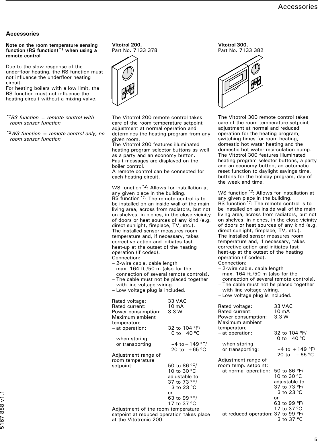
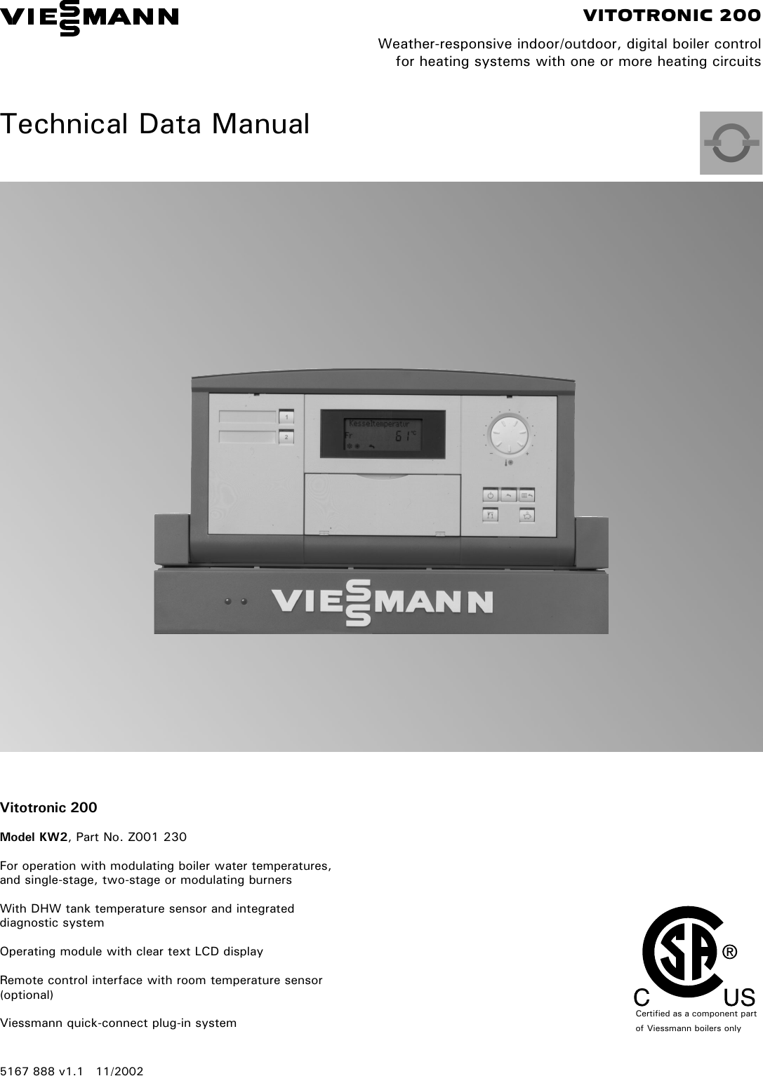
Viessmann Vitotronic 200 300 Technical Manual 5167 888 V1.1
Контроллер Vitotronic 200 тип KW5 с октября 2011 г замена на новую модель KO2B. Регулирование — погодозависимая теплогенерация, переменная.
Vitotronic 200 KW4 Viessmann Контроллер

Vitotronic 200−H, HK3W. VITOTRONIC 200−H. Инструкция по монтажу и сервисному обслуживанию для специалиста. Vitotronic 200−Н. Тип НК1W и НК3W.
Vitotronic 200 KW5 Viessmann Контроллер

Инструкция по монтажу и сервисному обслуживанию для специалистов. VIESMANN. Vitotronic 200. Тип KO1B, KO2B. Контроллер погодозависимого.
VITOTRONIC 200 Installation And Service Instructions | Manualzz

Ensure all requirements below are understood and fulfilled (including detailed information found in manual subsections. ▫Licensed professional heating.
VIESMANN. Инструкция По Эксплуатации VITOTRONIC 200. Для.

Viessmann Vitodens 200-W 80 кВт контроллер Vitotronic 200 газовые конденсационные котлы за 384 420 руб. Сделать заказ можно на сайте и по.
Viessmann Vitotronic 200-H, HK1B Controller Download Instruction.

Инструкция по сервисному обслуживанию для специалистов. VIESMANN. Vitotronic 200. Тип WO1C. Контроллера теплового насоса. VITOTRONIC 200.
Vitotronic 200 Инструкция :: Haybrenlites

Инструкция на Контроллер котлового контура Viessmann серии Vitotronic 200 тип KO1B, KO2B бренда Viessmann — скачать бесплатно в формате pdf.
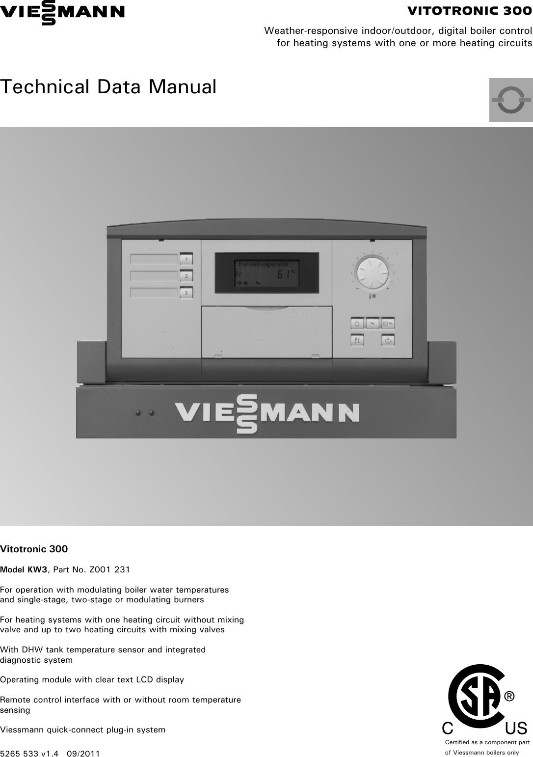
Viessmann Vitotronic 200 300 Technical Manual 5265 533 V1.4
Инструкция по эксплуатации для пользователя установки. Vitotronic 200−Н. Тип НК3W и НК3S. Контроллеры погодозависимого цифрового программного.
Viessmann Vitotronic 200, KW2 Controller Download Instruction.

View and Download Viessmann Vitotronic 200-h installation and service instructions manual online. Weather-compensated, digital heating circuit control units.
Viessmann Vitotronic 200 300 Technical Manual 5167 888 V1.1
Vitotronic 200, тип KO1B, KO2B или KW6B. Данная инструкция по эксплуатации предназначена. Ваш контроллер Vitotronic управляется контрол.
Vitotronic 200 KO2B Installation Manual | Manualzz
Каскадный контроллер Vitotronic 300-K объединяет до восьми. Vitodens 200- W в единую отопительную установку. При этом мощ- ность водогрейных.
Контроллер Vitotronic 200 Тип KW4 По Выгодной Цене В Интернет.

Инструкция по эксплуатации для пользователя установки. VIESMANN. Отопительная установка с контроллером Vitotronic 200, тип. HO1B для режима.
Vitotronic 200 KW5 Viessmann Контроллер

VIESMANN. Отопительная установка с контроллером для погодозависимой теплогенерации. Vitotronic 200, тип GW1B. Vitotronic 300, тип GW2B или.
Viessmann VITOTRONIC 200 Manuals | ManualsLib
Инструкция по монтажу и сервисному обслуживанию для специалиста. Vitotronic 200. Тип KW4. Контроллер погодозависимого цифрового программного.
Vitotronic 200 H Hk3w Инструкция
Контроллер Vitotronic 200 с жидко-кристаллическим сенсорным экраном. Пользователи и сервисные специалистыотмечают простоту управления.
Viessmann Vitotronic 200, KW2 Technical Data Manual Page: 1

Контроллеры Vitotronic 200, тип CO1E и тип CO1I, предназначены для погодозависимого управления однокотловой установкой. Контроллер Vitotronic.
Viessmann VITOTRONIC 200 Manuals | ManualsLib
Указания относительно области действия инструкции см. на последней странице. 5869 705 GUS 3/2005. Просим хранить! Page 2.
Vitotronic 200 Manual Español

нагрев воды в емкостном водонагревателе (датчик водонагревателя в комплекте контроллера. управление одним отопительным контуром без.
Viessmann Vitodens 200-W (5,2 — 26,0 КВт), Vitotronic 200 (HO1B.

Viessmann VITOTRONIC 200 Pdf User Manuals. View online or download Viessmann VITOTRONIC 200 Service Instructions Manual, Installation And Service.
Viessmann VITOTRONIC 200 Manuals | ManualsLib
VITOTRONIC 200. Инструкция по эксплуатации для пользователя установки. Отопительная установка с контроллером погодозависимого цифрового.
-
Page 1
VIESMANN Installation and service instructions for contractors Vitotronic 200 Type KO1B, KO2B Weather-compensated, digital boiler control unit For applicability, see the last page VITOTRONIC 200 Please keep safe. 5458 905 GB 12/2014… -
Page 2
■ Statutory regulations for the protection of the envi- For replacements, use only original spare parts ronment supplied or approved by Viessmann. ■ Codes of Practice of the relevant trade associations All current safety regulations as defined by DIN, EN, Safety instructions for operating the system ■… -
Page 3
Safety instructions Safety instructions (cont.) If you smell flue gas Danger Flue gas can lead to life threatening poisoning. ■ Shut down the heating system. ■ Ventilate the installation site. ■ Close doors to living spaces to prevent flue gases from spreading. Flue systems and combustion air Ensure that flue systems are clear and cannot be sealed, for instance due to accumulation of conden-… -
Page 4: Table Of Contents
Changing the slope and level …………. 30 ■ Connecting the control unit to the LON ……….31 Example of a single boiler system with Vitotronic 200-H and ■ Vitocom 200 ………………31 Carrying out a LON subscriber check ……….32 ■…
-
Page 5
Index Index 6. Coding level 1 «General» group ………………34 Coding ………………..34 ■ «Boiler» group ………………35 Coding ………………..35 ■ «DHW» group ………………36 Coding ………………..36 ■ «Solar» group ………………36 «Heating circuit 1», «Heating circuit 2», «Heating circuit 3» group … 37 Coding ……………….. -
Page 6
Index Index (cont.) 12. Components Coding card ………………. 84 Fuse ………………….. 84 Sensors ………………..84 Boiler water, cylinder, buffer, flow and room temperature sensors ..84 ■ Outside temperature sensor …………… 85 ■ Flue gas temperature sensor, part no. 7452 531 …….. 85 ■… -
Page 7
Product information The Vitotronic 200, type KO1B and KO2B for weather-compensated operation are designed for use in single boiler systems. One heating circuit without mixer and 2 heating circuits with mixer can be controlled. -
Page 8: Installing The Control Unit Base
Vitotronic control unit installation Installing the control unit base Boiler installation instructions Fitting the top of the control unit for type KO1B Please note ‘Live’ voltage can lead to PCB damage. Switch OFF the power supply at the control unit. Fig.1…
-
Page 9: Opening The Control Unit
Vitotronic control unit installation Opening the control unit Type KO1B Fig.2…
-
Page 10: Type Ko2B
Vitotronic control unit installation Opening the control unit (cont.) Type KO2B Fig.3 Plugging in the coding card Only insert the boiler coding card supplied with the boiler pack (see table on page 84). Fig.4 Insert the boiler coding card through the opening in the cover into slot «X7».
-
Page 11: Type Ko1B
Vitotronic control unit installation Adjusting the high limit safety cut-out (if… (cont.) When adjusting the safety cut-out to 100 °C, never set the temperature controller higher than 75 °C. Type KO1B °C Fig.5 Slotted screw for EGO products Slotted screw for JUMO products…
-
Page 12: Type Ko2B
Vitotronic control unit installation Adjusting the high limit safety cut-out (if… (cont.) °C Fig.6 Slotted screw for Rathgeber products Slotted screw for JUMO products Type KO2B Fig.7…
-
Page 13: Adjusting The Temperature Controller (If Required)
Vitotronic control unit installation Adjusting the high limit safety cut-out (if… (cont.) °C Fig.8 Slotted screw for EGO products Slotted screw for JUMO products Adjusting the temperature controller (if required) The temperature controller is set to 75 °C in the deliv- 1.
-
Page 14: Type Ko1B
Vitotronic control unit installation Adjusting the temperature controller (if… (cont.) Type KO1B Fig.9 Type KO2B Fig.10…
-
Page 15: Overview Of Electrical Connections
Electrical connections Overview of electrical connections Danger Please note Incorrect wiring can lead to serious injury from Electronic assemblies can be damaged by static electrical current and result in appliance dam- loads. age. Prior to commencing work, touch an earthed ■…
-
Page 16: Inserting Cables/Leads And Applying Strain Relief
Electrical connections Overview of electrical connections (cont.) Plug Component Burner Power supply for accessories External burner start, stage 1 Inserting cables/leads and applying strain relief Blank off unnecessary apertures in the lower part of the control unit with cable grommets (not cut out). Cable with cast-on cable entry Cable without cast-on cable entry Connecting the sensors…
-
Page 17: Connecting The Pumps
Electrical connections Connecting the sensors (cont.) Wireless outside temperature sensor «Wireless base station» installation and service instructions Connecting the pumps Available pump connections Connections on the 230 V~ PCB Plug Component Heating circuit pump for heating circuit HC1/A1 sÖ Circulation pump for cylinder heating DHW circulation pump Pumps 230 V~ Pumps with power consumption greater than 2 A…
-
Page 18: Pumps 400 V
Electrical connections Connecting the pumps (cont.) Pumps 400 V~ For switching the contactor L1 L2 L3 N PE Rated current 4(2) A~ Recommended connecting H05VV-F3G 0.75 mm cable H05RN-F3G 0.75 mm Fig.14 Pump To the control unit Contactor External burner start Please note If the contact is closed, burner stage 1 is started and ‘Live’ contacts lead to short circuits or phase fail-…
-
Page 19: External Demand Via Switching Contact
Electrical connections External demand via switching contact Connection options: ■ Plug ■ EA1 extension (accessories, see page 91) Connection Please note ‘Live’ contacts lead to short circuits or phase fail- ure. The external connection must be potential- free. Plug EA1 extension Floating contact EA1 extension Floating contact…
-
Page 20: External Demand Via 0
Electrical connections External demand via 0 10 V input – (cont.) ≙ No default set boiler water temperature – ≙ Set value 10 °C ≙ 10 V Set value 100 °C [{{] 0-10V fÖ Ö Fig.17 External blocking via switching contact Connection options: Please note ■…
-
Page 21: Codes
To the control unit To the burner Burner without plug Install the mating plug from Viessmann or from the burner manufacturer; connect the burner cable. Extending two-stage/modulating burners, part no. 7404 960 The function extension is supplied with the boiler.
-
Page 22: Connecting An Atmospheric Burner
Electrical connections Extending two-stage/modulating burners, part… (cont.) Max. power consumption ■ Two-stage: 1 (0.5) A ■ Modulating: 0.1 (0.05) A Terminal codes T6, T7, T8 Control chain «Burner stage 2», via two- point controller Control chain «modulation controller», via three-point controller From the burner Modulating burner close Modulating burner open/stage 2 ON…
-
Page 23: Extension, Two-Stage Burner, Part No. 7827 417
Electrical connections Connecting an atmospheric burner (cont.) Terminal codes T1, T2 Control chain Burner fault Hours run meter Fig.20 To the control unit To the burner control unit Extension, two-stage burner, part no. 7827 417 The function extension is supplied with the boiler. BN BU BU BK BN Fig.21…
-
Page 24: Power Supply
Electrical connections Connecting an atmospheric burner (cont.) Colour coding to IEC 60757 BK Black BN Brown BU Blue Power supply Isolators for non-earthed conductors Danger ■ Install an isolator in the power cable to provide Incorrectly executed electrical installations can omnipolar separation from the mains for all active result in injuries from electrical current and in conductors, corresponding to overvoltage category…
-
Page 25: Power Supply For Several Accessories
Electrical connections Power supply (cont.) Power supply for several accessories Power supply for all accessories via the control unit Fig.22 Some accessories with direct power supply Fig.23 Boiler control unit EA1 extension and/or solar control module, Extension kit, mixer M2 type SM1 (internal fuse protection 2 A) (internal fuse protection 2 A)
-
Page 26: Control Unit Power Supply
Electrical connections Power supply (cont.) Control unit power supply 1. Check whether the power cable to the control unit has appropriate fuse protection. 2. Connect the power cable in the wiring chamber. 3. Insert plug into the control unit. fÖ Fig.24 Mains voltage 230 V~ Fuse (max.
-
Page 27: Testing The High Limit Safety Cut-Out
Commissioning Testing the high limit safety cut-out Type KO1B 1. Hold down the «test» key (position » «) until the 2. Release the «test» key. burner shuts down: The temperature controller » » is bridged. When 3. Wait until the boiler water temperature has dropped the boiler water temperature reaches the safety approx.
-
Page 28: Setting The Date And Time
Commissioning Setting the date and time The time and date need to be reset during commis- sioning and after a prolonged time out of use. Setting time and date Continue with Fig.27 Adjusting coding addresses The control unit must be adjusted subject to the sys- tem equipment level.
-
Page 29: Set Room Temperature, Adjusting
Commissioning Adjusting heating curves (cont.) Slope -5 -10 -15 -20 Outside temperature in °C Fig. 28 Example for outside temperature 14 °C − Underfloor heating system, slope 0.2 to 0.8 Low temperature heating system, slope 0.8 to 1.6 Heating systems with a boiler water temperature in excess of 75 °C, slope greater than 1.6 Set room temperature, adjusting Individually adjustable for each heating circuit.
-
Page 30: Changing The Slope And Level
Commissioning Adjusting heating curves (cont.) 3. Select heating circuit. 4. «Set room temperature» 2. «Heating» 5. Set the required value. 3. Select heating circuit. Reduced set room temperature 4. «Set reduced room temp» 5. Set the required value. 14 °C 3 °C B -20 Fig.
-
Page 31: Connecting The Control Unit To The Lon
Installation and service instructions ■ The data transfer via LON can take several minutes. Vitotronic 200-H Example of a single boiler system with Vitotronic 200-H and Vitocom 200 Fig.33 Boiler control unit Vitotronic 200-H Vitocom All codes detailed in the table are listed in the «General» group.
-
Page 32: Carrying Out A Lon Subscriber Check
Commissioning Connecting the control unit to the LON (cont.) Carrying out a LON subscriber check The subscriber check is used to test communication 4. Select subscriber. with the system devices connected to the fault man- ager. 5. Start the subscriber check with «OK». Preconditions: Note ■…
-
Page 33: Calling Up Coding Levels
Coding levels Calling up coding levels The display of the codes is specified by the heating 2. «Coding level 1» ■ system configuration. ■ The codes are divided into groups: 3. Select group. – «General» – «Boiler» 4. Select coding address. «DHW»…
-
Page 34: General» Group
The boiler circuit pump runs on after the burner has stopped. Subscriber no. 77:1 LON subscriber number 77:2 LON subscriber number adjustable from 1 to 99: 77:99 1 = Boiler control unit 90 = Vitotronic 200-H – 98 = Vitogate – 99 = Vitocom…
-
Page 35: Boiler» Group
Coding level 1 «General» group (cont.) Coding in the delivered condition Possible change Detached house/apartment building 7F:1 Detached house 7F:0 Apartment building Holiday program and time program for DHW heating can be set sepa- rately. Lock out controls 8F:0 Operation enabled in standard 8F:1 Operation blocked in standard menu menu and in extended menu.
-
Page 36: Dhw» Group
Coding level 1 «Boiler» group (cont.) Coding in the delivered condition Possible change Service status 24:0 No «Service» indication on the dis- 24:1 «Service» indicator is shown on the play display (the address is automatically set and must be manually reset after a service has been carried out).
-
Page 37: Heating Circuit 1″, «Heating Circuit 2», «Heating Circuit 3» Group
Coding level 1 «Solar» group (cont.) Coding in the delivered condition Possible change Flow rate solar circuit 0F:70 Solar circuit flow rate at the maxi- 0F:1 Flow rate adjustable from 0.1 to mum pump speed 7 l/min. 25.5 l/min; ≙ 0F:255 1 step 0.1 l/min.
-
Page 38
Coding level 1 «Heating circuit 1», «Heating circuit 2», «Heating circuit 3» group (cont.) Parameter address A5:… With heating circuit pump logic function: Heating circuit pump «OFF» > > – > – Coding in the delivered condition Possible change Extended economy function, adjusted outside temperature A6:36 Extended economy mode disa- A6:5… -
Page 39
Coding level 1 «Heating circuit 1», «Heating circuit 2», «Heating circuit 3» group (cont.) Parameter address With heating circuit pump logic function: b5:… Heating circuit pump «OFF» Heating circuit pump «ON» + 5 K < RT + 4 K > actual actual + 4 K… -
Page 40
Coding level 1 «Heating circuit 1», «Heating circuit 2», «Heating circuit 3» group (cont.) Coding in the delivered condition Possible change Party mode time limit F2:8 Time limit for party mode or exter- F2:0 No time limit nal operating program changeover F2:1 Time limit adjustable from 1 to 12 h via pushbutton: 8 h… -
Page 41: Coding
Coding level 2 «General» group Coding Coding in the delivered condition Possible change 00:1 One heating circuit without mixer 00:2 For system schemes, see the follow- A1 (heating circuit 1), without ing table DHW heating 00:10 Value address Description 00: … 1 heating circuit without mixer A1 (heating circuit 1), with DHW heating, is recognised automatically.
-
Page 42
Coding level 2 «General» group (cont.) Coding in the delivered condition Possible change 3b:2 External demand with set minimum boiler water temperature. Setting of set value in coding ad- dress «9b» in this group. 3b:3 External blocking 3b:4 External blocking with fault message 3b:5 Fault message input 3b:6… -
Page 43
77:1 LON subscriber number 77:2 LON subscriber number adjustable from 1 to 99: 77:99 1 = Boiler control unit 90 = Vitotronic 200-H – 98 = Vitogate – 99 = Vitocom 79:1 With LON communication module: 79:0 Control unit is not fault manager. -
Page 44: Boiler» Group
The outside temperature of the temperature. sensor connected to the control 97:2 The control unit sends the outside unit is used internally. temperature to the Vitotronic 200-H. 98:1 Viessmann system number (in 98:1 System number adjustable from 1 to conjunction with monitoring several systems via Vitocom 300).
-
Page 45
Coding level 2 «Boiler» group (cont.) Coding in the delivered condition Possible change ERB80 function (values from 6 to 20 K) 06:74 Electronic maximum limit for boiler 06:20 Maximum limit adjustable from 20 to water temperature set to 74 °C. 127 °C. -
Page 46: Dhw» Group
Coding level 2 «Boiler» group (cont.) Coding in the delivered condition Possible change ≙ 1 step 100 h 23:0 No interval for burner service 23:1 Interval adjustable from 1 to 24 months. 23:24 24:0 No «Service» indication on the dis- 24:1 «Service»…
-
Page 47: Solar» Group
Coding level 2 «DHW» group (cont.) Coding in the delivered condition Possible change 59:0 Cylinder heating: 59:1 Start point adjustable from 1 to 10 K Start point 2.5 K below set value. – Stop point +2.5 K 59:10 5b:0 Do not adjust 5E:0 Circulation pump for cylinder heat- 5E:1…
-
Page 48
Frost protection function for solar 0b:1 Frost protection function for solar cir- circuit switched off cuit switched on (not required with Viessmann heat transfer medium) 0C:1 Delta T monitoring enabled 0C:0 Delta T monitoring disabled No flow rate captured in the solar circuit, or flow rate too low. -
Page 49
Coding level 2 «Solar» group (cont.) Coding in the delivered condition Possible change 10:0 Target temperature control switch- 10:1 Target temperature control switched ed off (see coding address «11») 11:50 Set solar DHW temperature 50 °C 11:10 The set solar DHW temperature is Target temperature control adjustable from 10 to 90 °C. -
Page 50: Heating Circuit 1″, «Heating Circuit 2», «Heating Circuit 3» Group
Coding level 2 «Solar» group (cont.) Coding in the delivered condition Possible change 27:15 Cyclical heating time 15 min 27:5 The cyclical heating time is adjusta- Once the DHW cylinder with priori- ble from 5 to 60 min. ty is heated up, the DHW cylinder 27:60 without priority is heated for a max- imum duration equal to the set cy-…
-
Page 51
Coding level 2 «Heating circuit 1», «Heating circuit 2», «Heating circuit 3» group (cont.) Parameter Heating circuit pump Address A3:… «On» «Off» 4 °C 2 °C – – – 3 °C 1 °C – – – 2 °C 0 °C –… -
Page 52
Coding level 2 «Heating circuit 1», «Heating circuit 2», «Heating circuit 3» group (cont.) Coding in the delivered condition Possible change A6:36 Extended economy mode disa- A6:5 Extended economy mode enabled, bled i.e. at a variably adjustable value be- A6:35 tween 5 and 35 °C plus 1 °C, the burner and heating circuit pump will stop and the mixer will close. -
Page 53
Coding level 2 «Heating circuit 1», «Heating circuit 2», «Heating circuit 3» group (cont.) Parameter address With heating circuit pump logic function: b5:… Heating circuit pump «OFF» Heating circuit pump «ON» + 3 K < RT + 2 K > actual actual + 2 K… -
Page 54
Coding level 2 «Heating circuit 1», «Heating circuit 2», «Heating circuit 3» group (cont.) Coding in the delivered condition Possible change Set day value adjustable at the re- E1:2 Set day temperature adjustable from mote control from 10 to 30 °C 17 to 37 °C E2:50 With remote control:… -
Page 55: Service Scans Calling Up The Service Menu
Service scans Calling up the service menu Press OK and simultaneously for approx. 4 s. «Service» «Diagnosis» Note «General» «Coding level 2» is only displayed if this level has been enabled: «Heating circuit 1/2/3» Press OK and simultaneously for approx. 4 s. «DHW»…
-
Page 56: Resetting Operating Data
Service scans Resetting operating data Display Explanation «Adjusted outside temp» The adjusted outside temperature is reset to the actual value. «Max. flue gas temp» Max. flue gas temp «Burner» Burner hours run «Burner starts» Burner starts «Fuel consumption» Fuel consumption In conjunction with a solar thermal system: «Diff t monitor»…
-
Page 57: Carrying Out An Actuator Test
Service scans Brief scan (cont.) Software ver- sion, EA1 exten- sion LON subnet address/system LON node address number SNVT config. Software ver- Software version, neuron chip Subscriber no. 0: Auto sion, commun- 1: Tool ic. coproc. Heating circuit HC1 Heating circuit HC2 Heating circuit HC3 Remote control Software ver-…
-
Page 58: Checking The Sensors
Service scans Carrying out an actuator test (cont.) Display Explanation «DHW circ pump» Actuator at output «Central fault message» Central fault message facility at output of EA1 exten- sion. «Htg circ pump HC2» Actuator at output sÖ of mixer extension kit (heating circuit with mixer M2) «Mixer HC2″…
-
Page 59: Calling Up Acknowledged Service Messages
Service scans Service indicator (cont.) 3. Reset code «24:1» to «24:0» in the «Boiler» group. 5. «Service functions» Note 6. «Service reset» If coding address «24» is not reset, «Service» will The selected service parameters for hours run and be displayed again on the following Monday. time intervals restart at 0.
-
Page 60: Troubleshooting Fault Display
Troubleshooting Fault display In the event of a fault, the red fault indicator on the For an explanation of the fault code see chapter «Fault control unit flashes. «Fault» is shown on the display codes». flashes. For some faults, the type of fault is also displayed in Press OK to display the fault code.
-
Page 61
Troubleshooting Fault messages (cont.) Displayed fault System characteristics Cause Measures code Operates as if the outside Communication error, Check wireless connection (place temperature was 0 °C. wireless outside tempera- wireless outside temperature sen- ture sensor sor close to the wireless base sta- tion). -
Page 62
Troubleshooting Fault messages (cont.) Displayed fault System characteristics Cause Measures code No heating of heating water Lead break, buffer tem- Check buffer temperature sensor buffer cylinder perature sensor (see page 84). Without buffer temperature sensor: Set code «52:0» in the «General» group. -
Page 63
Troubleshooting Fault messages (cont.) Displayed fault System characteristics Cause Measures code Control mode No flow rate in solar circuit Check solar circuit pump and solar or flow rate too low, or circuit. temperature limiter has re- Acknowledge fault message (see sponded. -
Page 64
Troubleshooting Fault messages (cont.) Displayed fault System characteristics Cause Measures code Control mode Communication error, Check connections (see EA1 extension page 91). Without EA1 extension: Set code «35:0» in the «General» group. Control mode Lead break, KM BUS to Check KM BUS cable and appli- solar control module or to ance. -
Page 65: Faults That Are Not Displayed At The Programming Unit
Troubleshooting Fault messages (cont.) Note «Subscriber fault» … is displayed in the case of LON subscriber faults. Faults that are not displayed at the programming unit Boiler cold, burner does not start Enable emissions test function (see operating instructions). ⇒ The pumps connected at the control unit are not running ■…
-
Page 66
Troubleshooting Faults that are not displayed at the… (cont.) ⇒ Heating circuit pump not running ■ Is plug ‘live’ between L and N? sÖ Check fuse F1, 6.3 A (slow). If the fuse has blown: 1. Check pump connection and pump. 1. -
Page 67: Parts Lists Ordering Parts
Parts lists Ordering parts The following details are required when ordering parts: ■ Serial no. (see type plate ■ Assembly (from this parts list) ■ Position number of the individual part within the assembly (from this parts list)
-
Page 68: Parts List Type Ko1B
Parts lists Parts list type KO1B 0081 0082 0084 0018 0074 0013 0099 0100 0101 0042 0109 0102 0104 0065 0070 0071 0072 Fig.36…
-
Page 69
Parts lists Parts list type KO1B (cont.) Pos. Part 0013 Casing, upper part (drawer) 0018 Programming unit 0042 Temperature sensor with plug 0065 Burner connecting cable with plug (for boilers with pressure-jet oil/gas burners) 0070 Power cable with plug fÖ 0071 5-core burner connecting cable with plug (for boilers with an intermittent ignition system) -
Page 70
Parts lists Parts list type KO1B (cont.) 0050 0054 0092 0090 0014 0052 0098 0016 0017 0051 0004 0035 0001 0097 0033 0031 0005 0030 0036 0011 0010 0040 Fig.37 Type plate… -
Page 71
Parts lists Parts list type KO1B (cont.) Pos. Part 0001 Cable clamp 0004 Stop dial for temperature controller 0005 Plug for high limit safety cut-out 0010 Front cover 0011 Front user panel, bottom right 0014 PCB covers 0016 Casing, lower section 0017 Back cover 0030… -
Page 72: Parts List Type Ko2B
Parts lists Parts list type KO2B 0081 0082 0017 0084 0010 0099 0100 0074 0007 0109 0101 0102 0040 0104 0042 0065 0071 0072 Fig.38…
-
Page 73
Parts lists Parts list type KO2B (cont.) Pos. Part 0007 Front cover 0010 Casing, upper part 0017 Casing, upper part, back 0040 Outside temperature sensor 0042 Temperature sensor with plug 0065 Burner connecting cable with plug (for boilers with pressure-jet oil/gas burners) 0071 5-core burner connecting cable with plug (for boilers with an intermittent ignition system) -
Page 74
Parts lists Parts list type KO2B (cont.) 0054 0050 0092 0090 0052 0033 0004 0014 0016 0031 0051 0098 0011 0018 0036 0005 0030 Fig.39… -
Page 75
Parts lists Parts list type KO2B (cont.) Pos. Part 0004 Stop dial for temperature controller 0005 Plug for high limit safety cut-out 0011 Front user panel 0014 Temperature controller bracket 0016 Casing, lower section 0018 Programming unit 0030 High limit safety cut-out 0031 Temperature controller 0033… -
Page 76: Function Description Boiler Water Temperature Control
Function description Boiler water temperature control Brief description The boiler water temperature is regulated by starting The boiler coding card specifies a minimum boiler ■ ■ or stopping the burner or through modulation. In the water temperature that must be maintained to protect delivered condition, the switching differential is 2 K, the boiler.
-
Page 77: Control Sequence For Burner Switching Hysteresis Of 4 K
Function description Boiler water temperature control (cont.) Time average high heat demand heat demand heat demand Fig.42 Control sequence for burner switching hysteresis of 4 K Boiler goes cold Boiler heats up (Set value 2 K) (set value +2 K) –…
-
Page 78
Function description Heating circuit control unit (cont.) Room temperature The duration of the pump idle time selected via cod- ■ ing address «A9» in the «Heating circuit…» group In conjunction with a remote control and room temper- has been reached. ature hook-up (coding address «b0″… -
Page 79
Function description Heating circuit control unit (cont.) Temperature profile 2: (ZV parquet and flooring tech- Temperature profile 7: Code «F1:15» nology) code «F1:2» Days Days Fig.49 Fig.44 System dynamics Temperature profile 3: Code «F1:3» You can influence the control characteristics of the mixers via coding address «C4». -
Page 80
Function description Heating circuit control unit (cont.) Delivered condition: 8 K. Raising the reduced room temperature The differential temperature is the minimum value by which the boiler water temperature should be higher During operation with reduced room temperature, the than the highest currently required flow temperature of reduced set room temperature can be automatically the heating circuit with mixer. -
Page 81: Control Sequence
Function description Heating circuit control unit (cont.) Example using the settings in the delivered condition Time Fig.52 Start of operation with standard room temperature Set boiler water/flow temperature in accordance with the selected heating curve Set boiler water/flow temperature in accordance with coding address «FA»: 50 °C + 20 % = 60 °C Duration of operation with raised set boiler water/…
-
Page 82: Cylinder Temperature Control
Function description Cylinder temperature control Brief description Cylinder temperature control is a constant tempera- ■ ture control. It operates by starting and stopping the circulation pump for cylinder heating. The switching differential is 2.5 K. ± ■ When the DHW cylinder is heated, the default set boiler water temperature is 20 K above the set DHW temperature (adjustable via coding address «60»…
-
Page 83: Control Sequence
Function description Cylinder temperature control (cont.) The set value range can be extended to 90 °C at cod- DHW heating can be blocked or enabled by switching ing address «56» in the «DHW» group. the heating program (see coding address «d5» in the «Heating circuit…»…
-
Page 84: Components
Components Coding card Boiler Coding card Display in brief scan Identification Part no. spare part Vitola 200, type VB2A, VX2A 00e1:02 7435 808 7834 995 Vitola 222, type VE2A Vitoladens 300-T, type VW3B Vitorond 100, type VR2B, 18 to 63 kW Vitorond 111, type RO2D Vitorondens 200-T, type BR2 and BR2A 01e1:02…
-
Page 85: Outside Temperature Sensor
Components Sensors (cont.) 1. Pull out corresponding plug. Viessmann NTC 10 k (blue marking) Ω 20.0 2. Check the sensor resistance and compare it with the curve. 10.0 3. In the case of severe deviation, check the installa- tion and replace the sensor if required.
-
Page 86: Radio Clock Receiver
Components Sensors (cont.) Viessmann NTC 20 k (orange marking) Ω Temperature in °C Fig.55 1. Pull out plug 3. In the case of severe deviation, check the installa- tion and replace the sensor if required. 2. Check the sensor resistance and compare it with the curve.
-
Page 87: Checking The Reception
Part no. 7301 063 For wall mounting For mixer mounting Components: Components: Mixer PCB with terminals for separate mixer motor Mixer PCB with mixer motor for Viessmann ■ ■ Flow temperature sensor as contact temperature sensor with mixers (not for flanged mixers) ■…
-
Page 88: Rotary Selector Setting
Components Mixer extension kit (cont.) Fig.57 A1 Main PCB F1 MCB/fuse S1 Rotary selector Plugs 230 V~ LV plug Heating circuit pump (on site) Flow temperature sensor sÖ Power supply 230 V/50 Hz Return temperature sensor (here without fÖ function) Power supply for accessories KM BUS cable for connection with the fÖ…
-
Page 89: Specification
Components Mixer extension kit (cont.) Specification Rated voltage 230 V~ Rated frequency 50 Hz Rated current Power consumption Wall mounting 1.5 W ■ Mixer mounting 5.5 W ■ Safety category IP rating IP 32 D to EN 60 529, ensure through design/installa- tion Permissible ambient temperature Operation…
-
Page 90: Changing The Rotational Direction Of The Mixer Motor
Components Mixer extension kit (cont.) Changing the rotational direction of the mixer motor 1. Remove the upper casing cover of the extension kit. Danger An electric shock can be life-threatening. Before opening the boiler, disconnect from the mains voltage, e.g. at the fuse or the mains isolator.
-
Page 91: Ea1 Extension, Part No. 7452 091
Components EA1 extension, part no. 7452 091 Fig.61 MCB/fuse Power supply fÖ Digital input 1 Power supply for additional accessories fÖ Digital input 2 Switching contact (floating) Digital input 3 KM BUS 10 V 0 10 V input – – Digital inputs DE1 to DE3 Functions: When connecting external contacts, observe the…
-
Page 92: Analogue Input 0
Components EA1 extension, part no. 7452 091 (cont.) Input function assignment Duration of the operating program changeover Select the input functions by means of the following The changeover only occurs for as long as the switch- codes in the «General» group at the boiler control unit: ing contact is closed.
-
Page 93: External Extension H5, Part No. 7199 249
Components External extension H5, part no. 7199 249 Connections at plug aBÖ ■ External burner blocking ■ External safety equipment ■ Provisional burner operation Flue gas damper ■ Please note ‘Live’ contacts lead to short circuits or phase fail- ure. The external connections must be potential- free.
-
Page 94: Motorised Flue Gas Damper
Components External extension H5, part no. 7199 249 (cont.) Motorised flue gas damper Part no.: 9586 971 to 975 ■ ■ 9589 074 ■ 9542 627 EIN EIN N STB TR TR 1 2 3 Fig.64 Plug aBÖ Flue gas damper motor Limit switch If making this connection, remove jumper «TR –…
-
Page 95: Vitoair Draught Stabiliser, Part No. 7338 725, 7339 703
Components Vitoair draught stabiliser, part no. 7338 725, 7339 703 Fig.65 To the burner To the control unit Colour coding to IEC 60757 Black GNYE Green/Yellow Function check Press the rotary selector on the motor and simultane- ously turn it to its central position. ⇒…
-
Page 96: Designations In The System Examples
System examples Designations in the system examples 2/52M1 2/52M2 2/21 2/21 2/28 2/5Sol 26/S2 Fig.67…
-
Page 97: System Example 1, Id: 4605372_1404_04
Boiler with Control unit Vitola 200, 222 or Vitoladens 300-T with Vitotronic 200, type KO1B ■ Vitorond 100, 111, Vitogas 200-F or Vitorondens 200-T, 222-F with Vitotronic 200, type KO2B ■ Outside temperature sensor ATS Boiler water temperature sensor KTS…
-
Page 98
System examples System example 1, ID: 4605372_1404_04 (cont.) Pos. Designation DHW heating by the boiler DHW cylinder (integrated for the Vitorond 111, Vitola 222 and Vitorondens 222-F) Cylinder temperature sensor STS DHW circulation pump ZP Circulation pump for cylinder heating UPSB Heating circuit 1 Heating circuit pump, heating circuit A1 Divicon heating circuit distributor… -
Page 99
System examples System example 1, ID: 4605372_1404_04 (cont.) Pos. Designation Radio clock receiver KM BUS distributor, in there are several KM BUS subscribers KM BUS subscribers: EA1 extension ■ Vitotrol 200A ■ Vitotrol 300A ■ Wireless base station ■ Vitocom 100, type GSM2 ■… -
Page 100
System examples System example 1, ID: 4605372_1404_04 (cont.) Electrical installation scheme HC M2 230 V/50 Hz VTS M2 UPSB 40 M2 Ö 0-10V zO uR KM BUS distributor zT zZ uP oO KM BUS Fig.69… -
Page 101: System Example 2, Id: 4605373_1404_04
System examples System example 2, ID: 4605373_1404_04 One heating circuit without mixer and 2 heating circuits with mixer plus DHW heating (optional solar DHW heating) Hydraulic installation scheme Flow Return —51/2— —51/20— —41/2— —51/20— —2/20— —41/20— —51/52— —41/52— —26/24— —2/28— —2/21— -26/24- —-…
-
Page 102
Boiler with Control unit Vitola 200 or Vitoladens 300-T with Vitotronic 200, type KO1B ■ Vitorond 100, Vitogas 200-F or Vitorondens 200-T with Vitotronic 200, type KO2B ■ Outside temperature sensor ATS Boiler water temperature sensor KTS DHW heating by the boiler… -
Page 103
System examples System example 2, ID: 4605373_1404_04 (cont.) Pos. Designation Heating circuit 3 Extension kit, mixer M3 Components: Flow temperature sensor M3 (contact temperature sensor) Mixer PCB with mixer motor M3 Extension kit, mixer M3 Components: Mixer PCB and flow temperature sensor M3 (contact temperature sensor) Mixer motor M3 Temperature limiter for underfloor heating circuit Heating circuit pump M3 and 3-way mixer… -
Page 104
System examples System example 2, ID: 4605373_1404_04 (cont.) Pos. Designation Radio clock receiver KM BUS distributor, in there are several KM BUS subscribers KM BUS subscribers: EA1 extension ■ Vitotrol 200A ■ Vitotrol 300A ■ Wireless base station ■ Vitocom 100, type GSM2 ■… -
Page 105
System examples System example 2, ID: 4605373_1404_04 (cont.) Electrical installation scheme HK M2 230 V/50 Hz VTS M2 UPSB HC M3 VTS M3 KM BUS distributor zT zZ uP oO KM BUS 40 M2 Ö 0-10V Fig.71… -
Page 106: System Example 3, Id: 4605377_1404_04
Note: This scheme is a general example without shut-off valves or safety equipment. This does not replace the need for on-site engineering. Equipment required Pos. Designation Boiler with Control unit Vitogas 200-F with Vitotronic 200, type KO2B Outside temperature sensor ATS…
-
Page 107
System examples System example 3, ID: 4605377_1404_04 (cont.) Pos. Designation Shunt pump Boiler water temperature sensor KTS Temperature controller T1 Temperature controller T2 Contactor relay DHW heating by the boiler DHW cylinder Cylinder temperature sensor STS DHW circulation pump ZP Circulation pump for cylinder heating UPSB Heating circuit Extension kit with mixer M2… -
Page 108
System examples System example 3, ID: 4605377_1404_04 (cont.) Pos. Designation Alternatives to hardwired Vitotrol 200A and 300A remote controls Wireless base station Vitotrol 200 RF Vitotrol 300 RF with table-top dock Vitotrol 300 RF with wall mounting bracket Wireless outside temperature sensor Wireless repeater Radio clock receiver KM BUS distributor, in there are several KM BUS subscribers… -
Page 109
System examples System example 3, ID: 4605377_1404_04 (cont.) Electrical installation scheme KO2B HK M2 230 V/50 Hz X12 47 UPSB VTS M2 825Ω 40 M2 Ö 0-10V 71 72 KM BUS distributor KM BUS 65 66 70 100 Fig.73… -
Page 110: System Example 4, Id: 4605378_1404_04
KO2B Fig. 74 Note: This scheme is a general example without shut-off valves or safety equipment. This does not replace the need for on-site engineering. Equipment required Pos. Designation Boiler with Control unit Vitogas 200-F with Vitotronic 200, type KO2B…
-
Page 111
System examples System example 4, ID: 4605378_1404_04 (cont.) Pos. Designation Outside temperature sensor ATS Distribution pump Boiler water temperature sensor KTS Temperature controller T1 Contactor relay DHW heating by the boiler DHW cylinder Cylinder temperature sensor STS DHW circulation pump ZP Circulation pump for cylinder heating UPSB Heating circuit Extension kit with mixer M2… -
Page 112
System examples System example 4, ID: 4605378_1404_04 (cont.) Pos. Designation Alternatives to hardwired Vitotrol 200A and 300A remote controls Wireless base station Vitotrol 200 RF Vitotrol 300 RF with table-top dock Vitotrol 300 RF with wall mounting bracket Wireless outside temperature sensor Wireless repeater Radio clock receiver KM BUS distributor, in there are several KM BUS subscribers… -
Page 113
System examples System example 4, ID: 4605378_1404_04 (cont.) Electrical installation scheme KO2B HK M2 230 V/50 Hz X12 47 UPSB VTS M2 825Ω 40 M2 Ö 0-10V 70 71 KM BUS distributor KM BUS 65 66 69 66 100 Fig.75… -
Page 114: Connection And Wiring Dia
Connection and wiring diagram Connection and wiring diagram Fig.76 Type KO1B: Pushbutton Type KO2B: Terminals Main PCB Power supply, accessories/external demand/ Power supply unit PCB external blocking X12 External burner start Programming unit (stage 1) Coding card Optolink PCB LV plug Electrical interfaces Outside temperature sensor (radio clock receiver MCB/fuse…
-
Page 115: Specification
Specification Specification Rated voltage 230 V~ Rated frequency 50 Hz Rated current 6 A~ Power consumption Safety category IP rating IP 20 D to EN 60 529, ensure through design/installation Function Type 1 B to EN 60730-1 Permiss. ambient temperature Operation 0 to +40 °C ■…
-
Page 116: Settings And Equipment
Settings and equipment Settings and equipment Tick the modified function. Function in the delivered condition Modified function High limit safety cut-out set to 110 °C Changed to …°C Temperature controller set to 75 °C Changed to …°C Remote control With remote control Control without remote control Vitotrol 200 at heating circuit 1 Vitotrol 200 at heating circuit 2…
-
Page 117
Settings and equipment Settings and equipment (cont.) Function in the delivered condition Modified function Heating circuit 1 Heating mode/reduced mode Heating mode: Weather-compensated Weather-compensated Reduced mode: With room temperature hook-up Heating mode: With room temperature hook-up Reduced mode: Weather-compensated Heating mode/reduced mode: With room tempera- ture hook-up Heating circuit 2 Heating mode/reduced mode… -
Page 118
Settings and equipment Settings and equipment (cont.) Function in the delivered condition Modified function Without auxiliary function for DHW heating. With auxiliary function for DHW heating, input of a ■ second set value of …ºC. Connected accessories Mixer extension kit for heating circuit with mixer, heating circuit 2 Mixer extension kit for heating circuit with mixer, heating circuit 3… -
Page 119: Keyword Index
Keyword index Keyword index External blocking…………20 Actuator test, carrying out………. 57 External burner start………..18 Adaptive cylinder heating……….. 83 External demand Adjusting the set room temperature……29 – Via 0 10 V input………… 19 – Adjusting the temperature controller……13 – Via switching contact……….19 Apartment building………….
-
Page 120
Wiring diagram…………114 Set DHW temperature……….82 Settings and equipment……….116 Applicability Serial No.: 7441800 7441802 Viessmann Werke GmbH&Co KG Viessmann Limited D-35107 Allendorf Hortonwood 30, Telford Telephone: +49 6452 70-0 Shropshire, TF1 7YP, GB Fax: +49 6452 70-2780 Telephone: +44 1952 675000 www.viessmann.com…

Installation and service
instructions
VIESMANN
for contractors
Vitotronic 200
Type KO1B, KO2B
Weather-compensated, digital boiler control unit
For applicability, see the last page
VITOTRONIC 200
5458 905 GB
1/2011
Please keep safe.
Safety instructions
Safety instructions
Please follow these safety instructions closely to prevent accidents and material losses.
Safety instructions explained
Danger
This symbol warns against the
risk of injury.
!
Please note
This symbol warns against the
risk of material losses and environmental pollution.
Note
Details identified by the word "Note" contain additional information.
■ all current safety regulations as
defined by DIN, EN, DVGW, TRGI,
TRF, VDE and all locally applicable
standards,
■ Gas Safety (Installation & Use) Regulations
– the appropriate Building Regulation
either the Building regulations, the
Building Regulation (Scotland),
Building Regulations (Northern Ireland),
– the Water Fittings Regulation or
Water Bylaws in Scotland,
– the current I.E.E. Wiring Regulations.
Target group
If you smell gas
Regulations
Observe the following when working on
this system
■ all legal instructions regarding the prevention of accidents,
■ all legal instructions regarding environmental protection,
■ the Code of Practice of relevant trade
associations,
2
Danger
Escaping gas can lead to explosions which may result in serious
injury.
■ Never smoke. Prevent naked
flames and sparks. Never
switch lights or electrical appliances ON or OFF.
■ Close the gas shut-off valve.
■ Open windows and doors.
■ Remove all people from the
danger zone.
■ Notify your gas or electricity
supplier from outside the building.
■ Shut off the electricity supply to
the building from a safe place
(outside the building).
5458 905 GB
These instructions are exclusively
designed for qualified personnel.
■ Work on gas equipment must only be
carried out by a qualified gas fitter.
■ Work on electrical equipment must
only be carried out by a qualified electrician.
■ The system must be commissioned by
the system installer or a qualified person authorised by the installer.
Safety instructions
Safety instructions (cont.)
If you smell flue gas
Danger
Flue gas can lead to life-threatening poisoning.
■ Shut down the heating system.
■ Ventilate the boiler room.
■ Close all doors leading to the
living space.
Working on the system
■ When using gas as fuel, also close the
main gas shut-off valve and safeguard
against unauthorised reopening.
■ Isolate the system from the power supply and check that it is no longer 'live',
e.g. by removing a separate fuse or by
means of a main isolator.
■ Safeguard the system against unauthorised reconnection.
!
Ancillary components, spare and
wearing parts
!
Please note
Spare and wearing parts which
have not been tested together
with the heating system can compromise its function. Installing
non-authorised components and
non-approved modifications/conversion can compromise safety
and may invalidate our warranty.
For replacements, use only original spare parts from Viessmann
or those which are approved by
Viessmann.
Please note
Electronic modules can be damaged by electro-static discharges.
Touch earthed objects, such as
heating or water pipes, to discharge static loads.
Repair work
Please note
Repairing components which fulfil a safety function can compromise the safe operation of your
heating system.
Replace faulty components only
with original Viessmann spare
parts.
5458 905 GB
!
3
Index
Index
Installation instructions
Preparing for installation
System example 1, ID: 4605372_1010_01.......................................................... 7
System example 2, ID: 4605373_1010_01.......................................................... 12
System example 3, ID: 4605377_1010_01.......................................................... 19
System example 4, ID: 4605378_1010_01.......................................................... 24
Installation sequence
Overview of electrical connections.......................................................................
Inserting cables and applying strain relief............................................................
Inserting the boiler coding card............................................................................
Changing the high limit safety cut-out setting (if required)...................................
Changing the thermostat setting (if required).......................................................
Connecting sensors..............................................................................................
Connecting pumps...............................................................................................
External burner start ............................................................................................
External demand..................................................................................................
External blocking..................................................................................................
Connecting a pressure-jet oil/gas burner.............................................................
Connecting an atmospheric burner......................................................................
Power supply........................................................................................................
Fitting the top part of the control unit for type KO1B............................................
Opening the control unit.......................................................................................
31
33
34
34
37
38
39
40
41
42
44
46
49
51
53
Commissioning
Changing the language........................................................................................
Setting the date and time.....................................................................................
Testing the high limit safety cut-out......................................................................
Matching coding addresses..................................................................................
Checking outputs (actuators) and sensors...........................................................
Adjusting heating curves......................................................................................
Connecting the control unit to the LON................................................................
55
55
55
56
57
58
61
Service scans
Calling up the service menu.................................................................................
Scanning operating data......................................................................................
Brief scan.............................................................................................................
Scanning and resetting the "Service" display.......................................................
64
64
65
67
Troubleshooting
Fault display......................................................................................................... 68
4
5458 905 GB
Service instructions
Index
Index
Faults that are not displayed at the programming unit......................................... 75
Function description
Boiler water temperature control.......................................................................... 78
Heating circuit control........................................................................................... 81
Cylinder temperature control................................................................................ 89
Code 1
Calling up coding level 1...................................................................................... 94
"General" group.................................................................................................... 95
"Boiler" group....................................................................................................... 97
"DHW" group........................................................................................................ 99
"Solar" group........................................................................................................ 99
"Heating circuit 1", "Heating circuit 2", "Heating circuit 3" group.......................... 102
Code 2
Calling up coding level 2...................................................................................... 108
"General" group.................................................................................................... 108
"Boiler" group ...................................................................................................... 115
"DHW" group........................................................................................................ 118
"Solar" group........................................................................................................ 120
"Heating circuit 1", "Heating circuit 2", "Heating circuit 3" group.......................... 126
Designs
Connection and wiring diagram............................................................................ 134
Components
Boiler coding card................................................................................................. 136
Sensors................................................................................................................ 136
Radio clock receiver, part no. 7450 563............................................................... 139
Extension kit for heating circuit with mixer........................................................... 141
Temperature limiter for limiting the maximum temperature.................................. 146
Extension EA1...................................................................................................... 147
External extension H5, part no. 7199 249............................................................ 149
Secondary air device Vitoair, part no. 7338 725, 7339 703................................. 152
5458 905 GB
Parts lists
Type KO1B........................................................................................................... 154
Type KO2B........................................................................................................... 157
Specification....................................................................................................... 160
Settings and equipment..................................................................................... 161
5
Index
Index (cont.)
5458 905 GB
Keyword index.................................................................................................... 165
6
Preparing for installation
System example 1, ID: 4605372_1010_01
One heating circuit without mixer and one heating circuit with
mixer and DHW heating
Applications
Heating system with different heat sources and methods of DHW heating
■ One heating circuit without mixer
■ One heating circuit with 3-way mixer
Main components
■ Oil condensing boiler, oil boiler or gas
boiler 18 to 100 kW
■ Heating circuit distribution
■ DHW cylinder
Function description
DHW heating
If the temperature falls below the set
DHW temperature at control unit 2, the
burner of boiler 1 starts and circulation
pump qE of DHW cylinder qP runs.
Within the periods selected at control
unit 2, DHW is heated with or without
priority control.
In case of absolute priority control, heating circuit pumps eQ/tR of the heating
circuits are switched off and mixer tT is
closed. With modulating priority control
of the heating circuit with mixer, heating
circuit pump tR remains on, and the
mixer tT closes far enough to enable the
set boiler water temperature for cylinder
heating to be reached. In this case, DHW
cylinder qP and heating circuit with
mixer tP are heated simultaneously.
5458 905 GB
Heating circuits eP/tP and DHW cylinder qP are regulated by boiler heating
circuit controller 1. The heating circuits
and DHW cylinder are each supplied by
a separate circulation pump eQ/tR and
qE.
The boiler heating circuit controller regulates the boiler water temperature in
weather-compensated mode (= flow
temperature of the heating circuit without
mixer) and the temperature level of the
heating circuit with mixer via an extension kit for one heating circuit with
mixer.
7
Installation
Heating mode
Preparing for installation
System example 1, ID: 4605372_1010_01 (cont.)
Hydraulic installation scheme
30
50
52
--51/2--
A1
--2/20--
31
M2
--51/20-53
--51/20--
54
--51/52--
--2--
13
--2/21--
--KM-BUS--
55
--52---20---230 V--
51
WW
12
--2/28--
--2/1--
3
10
1
--5---1---KM BUS---3---15--
KW
9
--2/5--
--2/3--
11
5458 905 GB
--230 V---20---96---21---28--
2
8
Preparing for installation
System example 1, ID: 4605372_1010_01 (cont.)
Pos.
1
2
3
9
qP
qQ
qW
qE
eP
eQ
tP
tQ
tW
tT
tQ
5458 905 GB
tW
tT
tE
tR
Designation
Boiler with
Control unit
■ Vitola 200, 222 or Vitoladens 300-T with Vitotronic 200, type KO1B
■ Vitorond 100, 111, Vitogas 200-F or Vitorondens 200-T, 222-F with
Vitotronic 200, type KO2B
Outside temperature sensor ATS
Boiler water temperature sensor KTS
DHW heating by the boiler
DHW cylinder (integrated for the Vitola 222, Vitorond 111 and Vitorondens
222-F)
Cylinder temperature sensor STS
DHW circulation pump ZP
Circulation pump for cylinder heating UPSB
Heating circuit I
Heating circuit pump, heating circuit A1
or
Divicon
Heating circuit II
Extension kit for one heating circuit with mixer M2
Components:
■ Flow temperature sensor M2
■ Mixer PCB with mixer motor
or
Extension kit for one heating circuit with mixer M2
Components:
■ Mixer PCB and flow temperature sensor
■ Mixer motor M2
Temperature limiter for an underfloor heating circuit
Heating circuit pump M2 and 3-way mixer
or
Divicon
9
Installation
Equipment required
Preparing for installation
System example 1, ID: 4605372_1010_01 (cont.)
Pos.
5
6
7
zW
zE
zR
zT
zZ
zU
zI
uP
5458 905 GB
zO
iP
iQ
Designation
Accessories (optional)
Two-stage/modulating burner extension
(Standard delivery for pos. 1)
Flue gas temperature sensor AGS
Extension EA1
Central fault message (requires external extension EA1)
External hook-up (requires extension EA1):
■ External blocking
■ External demand
■ External heating program changeover
External set value 0 to 10 V (requires extension EA1)
Vitotrol 200A
Vitotrol 300A
Radio clock receiver
KM BUS distributor, for several KM BUS subscribers
KM BUS subscriber:
■ Extension EA1 7
■ Vitotrol 200A zT
■ Vitotrol 300A zZ
■ Vitocom 100 uP
Vitocom 100, type GSM
or
Vitocom 200, type GP1
External extension H5
Motorised flue gas damper (only for the Vitogas 200-F)
10
Preparing for installation
System example 1, ID: 4605372_1010_01 (cont.)
Electrical installation scheme
68
2
96
230 V/ 50 Hz
L
1
L
2
145
40 EA1
230 V/ 50 Hz
N
80
7
41
2
X12
20
41
9
Low voltage
15
5
3
1
145
3
2
1
145
81
2
96
N
A1
31
M
1~
UPSB
13
N
M
1~
ZP
12
157
L
0-10 V
N
3
2
1
DE3
90
DE2
5
DE1
2
1
2
1
2
1
2
1
3
AGS
6
STS
11
KTS
9
1
2
7
40 A
145
ATS
40
P
Ö
S
S
4
3
145
LON
62
64
2
1
2
1
2
1
63
63
63
2
1
40
N
67
40 A
3
2
L
53
N
4
3
2
1
M2 51
L
51
N
L
2
1
KM BUS 65 66 70
40
L
M
1~
3
2
1
7
41
M
3
2
1
40 A
L
191
4
X12 47
N
L
28
7
7
150
N
21
145
Installation
40
N
M
1~
20
M2
54
M2
55
L
145 KM BUS 68
2
N
M
1~
52
69
2
2
1
145
2
1
VTS M2
52
5458 905 GB
2
1
11
Preparing for installation
System example 1, ID: 4605372_1010_01 (cont.)
Codes
Code
"00:5"
(is set automatically)
Group
"General"
"00:6"
(is set automatically)
"General"
"02:0"
(set by the boiler coding
card)
"Boiler"
System with one heating circuit without
mixer and one heating circuit with
mixer, without DHW cylinder
or
System with one heating circuit without
mixer and one heating circuit with
mixer, with DHW cylinder
Single stage burner operation
System example 2, ID: 4605373_1010_01
One heating circuit without mixer and two heating circuits with
mixer and DHW heating (optional solar DHW heating)
■ DHW cylinder (dual mode)
■ Solar thermal system
Function description
Applications
Heating system with different heat sources and methods of DHW heating
■ One heating circuit without mixer
■ Two heating circuits with 3-way mixer
The heating circuits eP/rP/tP and DHW
cylinder qP/qR are regulated by boiler
heating circuit controller 1. The heating
circuits and DHW cylinder are each supplied by a separate circulation pump eQ/
rR/tR and qE.
■ Oil condensing boiler, oil boiler or gas
boiler 18 to 100 kW
■ Heating circuit distribution
12
5458 905 GB
Main components
Preparing for installation
Heating mode
The boiler heating circuit controller regulates the boiler water temperature in
weather-compensated mode (= flow
temperature of the heating circuit without
mixer) and the temperature level of the
heating circuit with mixer via an extension kit for one heating circuit with
mixer.
DHW heating without a solar thermal
system
If the temperature falls below the set
DHW temperature at control unit 2, the
burner of boiler 1 starts and circulation
pump qE of DHW cylinder qP/qR runs.
Within the periods selected at control
unit 2, DHW is heated with or without
priority control.
In the case of absolute priority control,
heating circuit pumps eQ/rR/tR are
switched off and mixers rT/tT are
closed. With modulating priority control
of the heating circuits with mixer, heating
circuit pumps rR/tR remain on, and mixers rT/tT close far enough to enable the
boiler water temperature set for cylinder
heating to be reached. In this case, DHW
cylinder qP/qR and heating circuits with
mixer rP/tP are heated simultaneously.
5458 905 GB
DHW heating by the solar thermal
system
Solar circuit pump wE starts and DHW
cylinder qR is heated up, if the temperature differential between collector temperature sensor wQ and cylinder temperature sensor qT exceeds the start temperature differential.
Pump wE is stopped according to the following criteria:
■ The actual temperature drops below
the stop temperature differential
■ Exceeding the electronic temperature
limit (up to 90 °C) set in the solar control module (type SM1) wZ
■ The temperature selected at high limit
safety cut-out qZ (if installed) is
reached
Demands for the auxiliary function are
met by circulation pump wR.
Suppression of reheating of the DHW
cylinder by the boiler in conjunction
with the solar control module
Reheating suppression takes place in
two stages.
Reheating DHW cylinder qR by boiler
1 is suppressed as soon as DHW cylinder qR is heated by collectors wP. For
this, the set DHW temperature for
reheating is reduced by boiler 1. Suppression remains active for a certain time
after solar circuit pump wE has been
switched off (up to max. 24 h).
In the case of uninterrupted heating by
collectors wP (> 2 h), boiler 1 will only
reheat, if the set DHW temperature (coding address "67") selected at control unit
2 is not achieved.
In control unit 2, coding address "67"
defaults a third set DHW temperature
(setting range 10 to 95 °C). This value
must be below the first set DHW temperature.
DHW cylinder qR will only be heated by
boiler 1 when this set value is no longer
achieved by the solar thermal system.
13
Installation
System example 2, ID: 4605373_1010_01 (cont.)
Preparing for installation
System example 2, ID: 4605373_1010_01 (cont.)
Hydraulic installation scheme
Return
A1
M2
26
--2/20--
31
--41/20--
44
55
12
51
--52---20---230 V--
--2--
41
--52---20---230 V--
WW
--KM-BUS--
13
--2/21--
---26/24--
54
--51/52-45
23
M3
--51/20-53
--51/20--
--41/52-22
50
52
--51/2--
--2--
20
40
42
--41/2--
--KM-BUS--
Flow
21
--230 V---24---22--
--26/6--
--6---5---KM-BUS--
30
--2/28--
--2/1--
3
11
9
--
--2/3--
24
--26/22--
16
--2/5--
-26/24-
25
15
--26/5--
10 / 14
1
--5---1---KM BUS---3---15--
KW
5458 905 GB
--230 V---20---96---21---28--
2
14
Preparing for installation
System example 2, ID: 4605373_1010_01 (cont.)
Pos.
1
2
3
9
qP/qR
qQ
qW
qE
5458 905 GB
qT
qZ
wP
wQ
wW
wE
wR
wT
wZ
wU
eP
eQ
Designation
Boiler with
Control unit
■ Vitola 200 or Vitoladens 300-T with Vitotronic 200, type KO1B
■ Vitorond 100, Vitogas 200-F or Vitorondens 200-T with Vitotronic 200,
type KO2B
Outside temperature sensor ATS
Boiler water temperature sensor KTS
DHW heating by the boiler
DHW cylinder/dual
Cylinder temperature sensor STS
DHW circulation pump ZP
Circulation pump for cylinder heating UPSB
DHW heating by the solar thermal system
Cylinder temperature sensor SOL
High limit safety cut-out STB
Solar collectors
Collector temperature sensor KOL
Solar-Divicon
Solar circuit pump
Circulation pump (transfer)
Automatic thermostatic mixing valve
Solar control module, type SM1
Junction box
Heating circuit I
Heating circuit pump, heating circuit A1
or
Divicon
15
Installation
Equipment required
Preparing for installation
Pos.
rP/tP
rQ/tQ
rW/tW
rT/tT
rQ/tQ
rW/tW
rT/tT
tE
rR/tR
5
6
7
zW
zE
zR
zT
zZ
zU
zI
uP
zO
iP
iQ
16
Designation
Heating circuits II and III
Extension kit for one heating circuit with mixer M2/M3
Components:
■ Flow temperature sensor M2/M3
■ Mixer PCB with mixer motor
or
Extension kit for one heating circuit with mixer M2/M3
Components:
■ Mixer PCB and flow temperature sensor
■ Mixer motor M2/M3
Temperature limiter for an underfloor heating circuit
Heating circuit pump M2/M3 and 3-way mixer
or
Divicon
Accessories (optional)
Two-stage/modulating burner extension
(Standard delivery for pos. 1)
Flue gas temperature sensor AGS
Extension EA1
Central fault message (requires external extension EA1)
External hook-up (requires extension EA1):
■ External blocking
■ External demand
■ External heating program changeover
External set value 0 to 10 V (requires extension EA1)
Vitotrol 200A
Vitotrol 300A
Radio clock receiver
KM BUS distributor, for several KM BUS subscribers
KM BUS subscriber:
■ Extension EA1 7
■ Vitotrol 200A zT
■ Vitotrol 300A zZ
■ Vitocom 100 uP
■ Solar control module, type SM1 wZ
Vitocom 100, type GSM
or
Vitocom 200, type GP1
External extension H5
Motorised flue gas damper (only for the Vitogas 200-F)
5458 905 GB
System example 2, ID: 4605373_1010_01 (cont.)
Preparing for installation
System example 2, ID: 4605373_1010_01 (cont.)
Electrical installation scheme
68
2
96
N
L
1
L
2
40 EA1
N
80
7
41
2
230 V/ 50 Hz
X12
7
41
4
150
145
7
3
2
1
145
3
2
1
145
M
X12 47
N
M
1~
L
N
28
L
N
L
191
9
15
5
3
1
145
A1
81
N
40
UPSB
13
M
1~
ZP
12
AGS
6
0-10 V
2
1
STS
11
DE2
DE1
2
1
3
KTS
9
67
1
2
7
40 A
145
ATS
3
M2 41
S
4
3
62
64
2
1
2
1
2
1
63
63
63
2
1
40
N
40 A
2
69
40
M3
51
M2
44
L
N
20
145 KM BUS 68
2
40
L
P
Ö
S
41
N
L
2
1
LON
157
5
2
1
2
1
4
3
2
1
N
40 A
31
M
1~
90
KM BUS 65 66 70
7
2
96
DE3
3
2
1
3
2
1
41
L
20
21
Low voltage
145
230 V/ 50 Hz
Installation
40
L
M
1~
N
M
1~
52
2
1
145
2
1
VTS M2
42
M3
51
145
5458 905 GB
2
1
2
M2 45
17
Preparing for installation
System example 2, ID: 4605373_1010_01 (cont.)
41
40 A
51
N
40
L
N
40 A
4
40
SM1 26
L
53
N
M
1~
20
M3
54
M3
55
L
N
M
1~
52
2
2
1
145
2
1
VTS M3
52
41
145
2
1
26
51
40 A
N
L
40
27
24
N
M
1~
L
22
N
L
PWM
10
7
6
5
2
1
2
1
4
3
2
1
4
3
2
1
M
1~
UP
23
STB
16
UP
24
KOL
21
SOL
15
145
Codes
Group
"General"
"00:10"
(is set automatically)
"General"
"02:0"
(set by the boiler coding
card)
"Boiler"
18
System with one heating circuit without
mixer and two heating circuits with
mixer, without DHW cylinder
or
System with one heating circuit without
mixer and two heating circuits with
mixer, with DHW cylinder
Single stage burner operation
5458 905 GB
Code
"00:9"
(is set automatically)
Preparing for installation
System example 3, ID: 4605377_1010_01
Single boiler system: Vitogas with one heating circuit with mixer
and shunt pump for return temperature raising
Size shunt pump 4 to approx. 30 % of
the maximum boiler flow rate.
Applications
Heating system and DHW heating
■ One heating circuit with 3-way mixer
Main components
■ Vitogas 200-F (from 72 kW)
■ Vitotronic 200, type KO2B
■ Shunt pump for raising the return temperature
■ DHW cylinder
Function description
Heating mode
The boiler heating circuit controller regulates the boiler water temperature in
weather-compensated mode (= flow
temperature of the heating circuit without
mixer) and the temperature level of the
heating circuit with mixer via an extension kit for one heating circuit with
mixer.
5458 905 GB
Heating circuit tP and DHW cylinder
qP are regulated by boiler heating circuit
controller 1. The heating circuit and the
DHW cylinder are supplied by their individual circulation pumps tR and qE.
Thermostat T2 qT starts the shunt pump
if the actual temperature falls below the
required minimum return temperature.
The flow rate must be reduced by at least
50 % via thermostat T1 qR if the minimum return temperature is not achieved
even with return temperature raising.
If the temperature falls below the set
DHW temperature at control unit 2, the
burner of boiler 1 starts and circulation
pump qE of DHW cylinder qP runs.
Within the periods selected at control
unit 2, DHW is heated with or without
priority control.
In the case of absolute priority control,
heating circuit pump tR of the heating
circuit is switched off and mixer tT is
closed. With modulating priority control
of the heating circuit with mixer, heating
circuit pump tR remains on, and the
mixer tT closes far enough to enable the
set boiler water temperature for cylinder
heating to be reached. In this case, DHW
cylinder qP and heating circuit with mixer
tP are heated simultaneously.
19
Installation
DHW heating
Preparing for installation
System example 3, ID: 4605377_1010_01 (cont.)
Hydraulic installation scheme
50
52
--51/2-M2
--51/20-53
--51/20--
54
--51/52--
--2--
13
--2/21--
--KM-BUS--
55
--52---20---230 V--
51
WW
12
--2/1--
3
10
14
--51/2--
4
9
--2/5--
1
--5---1---KM BUS---3---15--
KW
15
--51/20--
--2/3--
11
--51/20--
--2/28--
--230 V---20---96---21---28--
2
5458 905 GB
Note: This scheme is a basic example without shut-off valves or safety equipment.
This does not replace the local technical engineering task.
20
Preparing for installation
System example 3, ID: 4605377_1010_01 (cont.)
Equipment required
3
4
9
qR
qT
qZ
qP
qQ
qW
qE
tP
tQ
tW
tT
tQ
5458 905 GB
tW
tT
tE
tR
Designation
Boiler with
Control unit
■ Vitogas 200-F with Vitotronic 200, type KO2B
Outside temperature sensor ATS
Shunt pump
Boiler water temperature sensor KTS
Control thermostat T1
Control thermostat T2
Contactor relay
DHW heating by the boiler
DHW cylinder
Cylinder temperature sensor STS
DHW circulation pump ZP
Circulation pump for cylinder heating UPSB
Heating circuit
Extension kit for one heating circuit with mixer M2
Components:
■ Flow temperature sensor M2
and
■ Mixer PCB with mixer motor
or
Extension kit for one heating circuit with mixer M2
Components:
■ Mixer PCB and flow temperature sensor
■ Mixer motor M2
Temperature limiter for an underfloor heating circuit
Heating circuit pump M2 and 3-way mixer
or
Divicon
Installation
Pos.
1
2
21
Preparing for installation
System example 3, ID: 4605377_1010_01 (cont.)
Pos.
5
6
7
wI
zW
zE
zR
zT
zZ
zU
zI
uP
5458 905 GB
zO
iP
iQ
Designation
Accessories (optional)
Two-stage/modulating burner extension
(Standard delivery for pos. 1)
Flue gas temperature sensor AGS
Extension EA1
Resistance 825 Ω
Central fault message (requires external extension EA1)
External hook-up (requires extension EA1):
■ External blocking
■ External demand
■ External heating program changeover
External set value 0 to 10 V (requires extension EA1)
Vitotrol 200A
Vitotrol 300A
Radio clock receiver
KM BUS distributor, for several KM BUS subscribers
KM BUS subscriber:
■ Extension EA1 7
■ Vitotrol 200A zT
■ Vitotrol 300A zZ
■ Vitocom 100 uP
Vitocom 100, type GSM
or
Vitocom 200, type GP1
External extension H5
Motor-controlled flue gas damper
22
Preparing for installation
System example 3, ID: 4605377_1010_01 (cont.)
Electrical installation scheme
68
2
230 V/ 50 Hz
L
96
2
1
L
145
40 EA1
N
230 V/ 50 Hz
80
7
41
2
X12
20
145
7
7
41
4
150
3
2
1
145
3
2
1
145
41
M
2
N
40
L
N
N
40 A
L
157
N
21
28
L
N
L
191
9
15
Low voltage
5
3
1
M
1~
UPSB
13
M
1~
ZP
12
0-10 V
DE3
3
2
1
90
DE2
5
DE1
2
1
2
1
AGS
6
2
1
STS
11
KTS
9
1
2
145
LON
M2 51
P
Ö
S
S
4
3
62
64
2
1
2
1
2
1
63
63
63
2
1
M
1~
67
2
1
4
3
2
1
40
L
16
2
1
3
ATS
3
7
40 A
51
N
40
L
145
KM BUS 65 66 70
7
81
96
X12 47
3
2
1
Installation
40
N
N
M
1~
40 A
2
20
69
4
T2
15
M2
54
L
145 KM BUS 68
2
BP
53
N
L
N
M
1~
52
2
1
2
2
1
145
2
1
28
825 Ω
M2
55
VTS M2
52
3
2
T1
14
5458 905 GB
1
23
Preparing for installation
System example 3, ID: 4605377_1010_01 (cont.)
Codes
Code
Set "00:3"
Group
"General"
Set "00:4"
"General"
"02:1"
(set by the boiler coding
card)
"Boiler"
System with one heating circuit with
mixer, without DHW cylinder
or
System with one heating circuit with
mixer, with DHW cylinder
Two-stage burner operation
System example 4, ID: 4605378_1010_01
Single boiler system: Vitogas with one heating circuit with mixer,
distribution pump and low pressure distributor
Function description
Heating system and DHW heating
■ One heating circuit with 3-way mixer
Main components
■ Vitogas 200-F (from 72 kW)
■ Vitotronic 200, type KO2B
■ Distribution pump and low pressure
distributor
■ DHW cylinder
24
DHW heating
If the temperature falls below the set
DHW temperature at control unit 2, the
burner of boiler 1 starts and circulation
pump qE of DHW cylinder qP runs.
5458 905 GB
Applications
Heating circuit tP and DHW cylinder
qP are regulated by boiler heating circuit
controller 1. The heating circuit and the
DHW cylinder are supplied by their individual circulation pumps tR and qE.
Temperature sensor T1 qR reduces or
closes mixer tT if the required minimum
return temperature is not achieved.
Size distribution pump 4 to 110 % of
the total heating system flow rate.
Observe the corresponding pressure
drop of the respective heat sources
when sizing pumps.
Preparing for installation
System example 4, ID: 4605378_1010_01 (cont.)
Heating mode
Installation
The boiler heating circuit controller regulates the boiler water temperature in
weather-compensated mode (= flow
temperature of the heating circuit without
mixer) and the temperature level of the
heating circuit with mixer via an extension kit for one heating circuit with
mixer.
5458 905 GB
Within the periods selected at control
unit 2, DHW is heated with or without
priority control.
In the case of absolute priority control,
heating circuit pump tR of the heating
circuit is switched off and mixer tT is
closed. With modulating priority control
of the heating circuit with mixer, heating
circuit pump tR remains on, and the
mixer tT closes far enough to enable the
set boiler water temperature for cylinder
heating to be reached. In this case, DHW
cylinder qP and heating circuit with mixer
tP are heated simultaneously.
25
Preparing for installation
System example 4, ID: 4605378_1010_01 (cont.)
Hydraulic installation scheme
50
52
--51/2-M2
--51/20-53
54
--51/52-55
4
--2--
13
--2/21--
--KM-BUS--
--51/20--
--51/20--
--52---20---230 V--
51
WW
12
--2/28--
3
--2/1--
14
--51/2--
10
1
--5---1---KM BUS---3---15--
KW
9
--2/5--
--2/3--
11
--230 V---20---96---21---28--
2
5458 905 GB
Note: This scheme is a basic example without shut-off valves or safety equipment.
This does not replace the local technical engineering task.
26
Preparing for installation
System example 4, ID: 4605378_1010_01 (cont.)
Equipment required
3
4
9
qR
qZ
qP
qQ
qW
qE
tP
tQ
tW
tT
tQ
5458 905 GB
tW
tT
tE
tR
Designation
Boiler with
Control unit
■ Vitogas 200-F with Vitotronic 200, type KO2B
Outside temperature sensor ATS
Distribution pump
Boiler water temperature sensor KTS
Control thermostat T1
Contactor relay
DHW heating by the boiler
DHW cylinder
Cylinder temperature sensor STS
DHW circulation pump ZP
Circulation pump for cylinder heating UPSB
Heating circuit
Extension kit for one heating circuit with mixer M2
Components:
■ Flow temperature sensor M2
and
■ Mixer PCB with mixer motor
or
Extension kit for one heating circuit with mixer M2
Components:
■ Mixer PCB and flow temperature sensor
■ Mixer motor M2
Temperature limiter for an underfloor heating circuit
Heating circuit pump M2 and 3-way mixer
or
Divicon
Installation
Pos.
1
2
27
Preparing for installation
System example 4, ID: 4605378_1010_01 (cont.)
Pos.
5
6
7
wI
zW
zE
zR
zT
zZ
zU
zI
uP
5458 905 GB
zO
iP
iQ
Designation
Accessories (optional)
Two-stage/modulating burner extension
(Standard delivery for pos. 1)
Flue gas temperature sensor AGS
Extension EA1
Resistance 825 Ω
Central fault message (requires external extension EA1)
External hook-up (requires extension EA1):
■ External blocking
■ External demand
■ External heating program changeover
External set value 0 to 10 V (requires extension EA1)
Vitotrol 200A
Vitotrol 300A
Radio clock receiver
KM BUS distributor, for several KM BUS subscribers
KM BUS subscriber:
■ Extension EA1 7
■ Vitotrol 200A zT
■ Vitotrol 300A zZ
■ Vitocom 100 uP
Vitocom 100, type GSM
or
Vitocom 200, type GP1
External extension H5
Motor-controlled flue gas damper
28
Preparing for installation
System example 4, ID: 4605378_1010_01 (cont.)
Electrical installation scheme
68
2
230 V/ 50 Hz
L
96
2
1
L
145
40 EA1
N
230 V/ 50 Hz
80
7
41
2
X12
20
145
7
7
41
4
150
X12 47
145
3
2
1
145
81
2
96
N
L
N
40 A
N
157
N
28
L
N
L
191
9
Low voltage
15
3
2
1
3
1
13
M
1~
ZP
12
0-10 V
90
DE2
5
DE1
2
1
2
1
2
1
UPSB
DE3
3
2
1
5
M
1~
AGS
6
STS
11
KTS
9
1
2
7
ATS
3
145
145
LON
P
Ö
S
S
4
3
62
64
2
1
2
1
2
1
63
63
63
2
1
40 A
N
40
N
40 A
2
145 KM BUS 68
2
M2 51
M
1~
VP
4
M
1~
M2
54
51
L
4
3
2
1
40
L
16
67
2
1
KM BUS 65 66 70
40
L
21
3
2
1
7
41
M
3
2
1
Installation
40
N
20
69
L
53
N
L
N
M
1~
52
2
1
2
2
1
145
2
1
28
825 Ω
M2
55
VTS M2
52
3
2
T1
14
5458 905 GB
1
29
Preparing for installation
System example 4, ID: 4605378_1010_01 (cont.)
Codes
Group
"General"
Set "00:4"
"General"
"02:1"
(set by the boiler coding
card)
"Boiler"
System with one heating circuit with
mixer, without DHW cylinder
or
System with one heating circuit with
mixer, with DHW cylinder
Two-stage burner operation
5458 905 GB
Code
Set "00:3"
30
Installation sequence
Overview of electrical connections
For opening the control unit, see
page 53.
The following illustrations show the bottom half of the control unit as viewed
from the back.
Type KO1B
45
51
14
9
19
15
1
1
14
5
28
21
20
5
15
1
19
28
X12
21
2
9
96
5458 905 GB
40
96
41
20
X1
3
41
40
Installation
1
3
5
31
Installation sequence
Overview of electrical connections (cont.)
Type KO2B
14
45
51
1
3
5
9
15
1
19
A
28
5
21
14
20
5
3
1
41
19
1
9
15
96
40
21
28
X12
20
X1
2
90
41
75
40
96
95
°C
A Temperature controller
lH
Power supply connection of accessories
X12 External burner start (stage 1)
Low voltage plugs
! Outside temperature sensor
§ Boiler water temperature sensor
% Cylinder temperature sensor
) Buffer temperature sensor (accessory)
aG Flue gas temperature sensor
(accessories)
5458 905 GB
230 V~ plugs
sÖ Heating circuit pump (heating circuit A1)
sA Circulation pump for cylinder heating (accessory)
sK DHW circulation pump (on site)
fÖ Power supply
fA Burner
32
Installation sequence
Overview of electrical connections (cont.)
■ When connecting external switching
contacts or components to the safety
LV of the control unit, the safety
requirements of protection class II, i.e.
8.0 mm air gap/creeping distance or
2.0 mm insulation thickness from 'live'
components must be observed.
■ For all on-site components (incl. PC/
laptops), ensure safe electrical separation to EN 60 335 or IEC 65.
Inserting cables and applying strain relief
Blank off unnecessary knockouts in the
lower part of the control unit with cable
grommets (not cut out).
Cable without moulded cable entry
Cable with moulded cable entry
3.
1.
2.
2.
5458 905 GB
1.
33
Installation
aVG KM BUS subscriber (accessory)
a:A Two-stage/modulating burner
extension (part of the standard
boiler delivery)
Installation sequence
Inserting the boiler coding card
9
15
5
3
1
14
5
Only use the boiler coding card included
with the boiler product documentation.
Insert the boiler coding card through the
recess in the cover into slot "X7".
Changing the high limit safety cut-out setting (if required)
In the delivered condition, the high limit
safety cut-out is set to 110 °C and can be
adjusted to 100 °C.
Note
The temperature value cannot be reset.
5458 905 GB
When adjusting the temperature to 100
ºC, never adjust the thermostat above
75 ºC.
34
Installation sequence
Changing the high limit safety cut-out setting… (cont.)
Type KO1B
2.
A
95
10
0
Installation
1.
0
11
120
°C
B
4.
3.
B JUMO slotted screw
5458 905 GB
A EGO slotted screw
35
Installation sequence
Changing the high limit safety cut-out setting… (cont.)
Type KO2B
A
95
10
0
B
11
0
120
°C
A EGO slotted screw
36
B JUMO slotted screw
5458 905 GB
1.
Installation sequence
Changing the thermostat setting (if required)
Note
Never set the thermostat above 75 ºC if
the high limit safety cut-out has been set
to 100 ºC.
!
Please note
Excessive DHW temperatures
can damage the DHW cylinder.
If the system is operated in conjunction with a DHW cylinder,
ensure that the maximum permissible DHW temperature is not
exceeded. If necessary, install
suitable safety equipment for this
purpose.
1. Remove rotary selector "R".
2. Using a pair of pointed pliers, break
off the cams between "75" and "90"
or "95" from the stop disc, as shown
in the diagram.
3. Install rotary selector "R" so that the
mark is between "75" and "90" or
"95". Turn rotary selector "R" fully
clockwise.
Type KO1B
2.
3.
5458 905 GB
1.
37
Installation
In the delivered condition, the thermostat
is set to 75 °C and can be adjusted to
87 °C/95 °C.
Installation sequence
Changing the thermostat setting (if required) (cont.)
Type KO2B
3.
2.
75
90
95
°C
1.
Connecting sensors
191
1 2 1 2
9
A
15
B
1 2 1 2
5
C
1 2 3
3
1
D
E
A Buffer temperature sensor
B Flue gas temperature sensor
C Cylinder temperature sensor
38
1 2 1 2
145
145
D Boiler water temperature sensor
E Outside temperature sensor
5458 905 GB
1 2
Installation sequence
Connecting sensors (cont.)
■ North or north-western wall, 2 to
2.5 m above ground level; in multistorey buildings, in the upper half of
the second floor
■ Not above windows, doors or ventilation outlets
■ Not immediately below balconies or
gutters
■ Never render over
Outside temperature sensor connection
2-core lead, up to 35 m long with a crosssection of 1.5 mm2
Installation
Installation point for outside temperature sensor
Connecting pumps
Available pump connections
sÖ Heating circuit pump A1
sA Circulation pump for cylinder heating
sK DHW circulation pump
Pumps 230 V~
M A
1~
Rated current
4(2) A~
Recommended
connecting cable H05VV-F3G
0.75 mm2
or
H05RN-F3G
0.75 mm2
B
5458 905 GB
A Pump
B To the control unit
39
Installation sequence
Connecting pumps (cont.)
Pumps 400 V~
N
L
L1 L2 L3 N PE
For controlling the contactor
Rated current
4(2) A~
Recommended
connecting cable H05VV-F3G
0.75 mm2
or
H05RN-F3G
0.75 mm2
A
M
B 3~
A Contactor
B Pump
External burner start
This function can be achieved with plug
"X12".
!
Please note
'Live' contacts lead to short circuits or phase failure.
The external connection must be
floating.
Connect the floating contact. If the contact is closed, the first burner stage is
started and the boiler water temperature
is regulated by the thermostat.
Rated voltage
Rated current
Recommended connecting cable
230 V~
6 A~
H05VV-F3G
0.75 mm2
A
1 2
A External start (floating contact)
40
5458 905 GB
X12
Installation sequence
External burner start (cont.)
Provisional burner operation
Insert the jumper between terminals 1
and 2 of plug "X12".
The first burner stage is on and the control thermostat will limit the boiler water
temperature.
External demand
Installation
This function can be achieved with plug
lH or extension EA1 (accessory, see
page 147).
Connection
Please note
'Live' contacts lead to short circuits or phase failure.
The external connection must be
floating.
5458 905 GB
!
41
Installation sequence
External demand (cont.)
Plug lH
Extension EA1
A
N?L 1
B
DE
[{A
DE
[{S
DE
[{D
lH
B
A
A Floating contact
A Floating contact
B Plug lH
B Extension EA1
Rated voltage
230 V~
Rated current
10 mA~
Recom. connecting cable H05VV-F3G
0.75 mm2
When the contact is closed, burner operation is load-dependent. The boiler water is
heated to the set value selected in the coding address "9b". The boiler water temperature is limited by this set value and the electronic maximum limit (coding address
"06") in the "Boiler" group.
Codes
Extension EA1
Plug lH
"40:1" in the "General" group Set "3A", "3b" or "3C" in the "General" group to 2.
Coding address "d7" in the "Heating circuit" group:
Effect of the function on the relevant heating circuit pump
Coding address "5F" in the "DHW" group:
Effect of function on circulation pump for cylinder heating
External blocking
5458 905 GB
This function can be achieved with plug
lH or extension EA1 (accessory, see
page 147).
42
Installation sequence
External blocking (cont.)
Connection
!
Please note
'Live' contacts lead to short circuits or phase failure.
The external connection must be
floating.
Plug lH
Extension EA1
N?L 1
B
DE
[{A
DE
[{S
Installation
A
DE
[{D
lH
A
B
A Floating contact
A Floating contact
B Plug lH
B Extension EA1
Rated voltage
230 V~
Rated current
10 mA~
Recom. connecting cable H05VV-F3G
0.75 mm2
When the contact is closed, the burner and the heating circuit pumps are switched
off, and the mixers are closed.
Please note
During the block, there is no frost
protection
of the heating system.
5458 905 GB
!
43
Installation sequence
External blocking (cont.)
Codes
Extension EA1
Plug lH
"40:2" in the "General" group Set "3A", "3b" or "3C" in the "General" group to 3 or
4.
Coding address "d6" in the "Heating circuit" group:
Effect of the function on the relevant heating circuit pump
Coding address "5E" in the "DHW" group:
Effect of function on circulation pump for cylinder heating
Connecting a pressure-jet oil/gas burner
Max. power consumption 4 (2) A.
5458 905 GB
The burner cable is included in the
standard delivery of the boiler.
Connect the burner in accordance with
DIN 4791 [or local regulations].
44
Installation sequence
Terminal codes
L1
Phase via high limit safety cutout to the burner
PE
Earth conductor to burner
N
Neutral conductor to burner
T1, T2 Control chain
S3
Burner fault
B4
Hours run meter
~
Signal pass direction:
Control unit → burner
|
Signal pass direction:
Burner → control unit
41
L1
TR
N
BZ
Störung H1
N
PE
L1
N T1 T2 S3 B4
STB
L
41
T1 T2 S3 B4
Equipment codes
STB Control unit high limit safety cutout
TR Control unit thermostat
H1 Burner fault signal
BZ Hours run meter
A To the control unit
B To the burner
Burner without plug
Install the mating plug from Viessmann
or from the burner manufacturer; connect the burner cable.
Extension of two-stage/mod. burners, part no. 7404 960
Observe coding addresses "02", "10" to
"13", "15" to "18", "1A", "26" and "29" in
the "Boiler" group in code 2.
5458 905 GB
This function extension is supplied with
the boiler.
Max. power consumption
■ Two-stage: 1 (0.5) A
■ Modulating: 0.1 (0.05) A
45
Installation
Connecting a pressure-jet oil/gas burner (cont.)
Installation sequence
Connecting a pressure-jet oil/gas burner (cont.)
A
BN BU BK
C
K1
K2
K1
K2
BN BK BU
Terminal codes
T6, T7, T8 Control chain "Burner stage
2 or modulation controller"
(for two-stage operation via
two-point controller; for
modulating operation via
three-point controller)
T6
From the burner
T7
Mod. burner closed
T8
Mod. burner open/stage 2
on
~
Signal pass direction:
Control unit → burner
|
Signal pass direction:
Burner → control unit
Colour coding to DIN IEC 60 757
BK black
BN brown
BU blue
B
A To the control unit
B To the burner
C Junction box with relay K1 and K2
Connecting an atmospheric burner
Connect the burner in accordance with
DIN 4791 [or local regulations].
5458 905 GB
The burner cable is included in the
standard delivery of the boiler.
46
Installation sequence
Connecting an atmospheric burner (cont.)
41
N T1 T2 S3 B4
L
B4 S3 T2 T1 N
L
Installation
Terminal codes
T1, T2 Control chain
S3
Burner fault
B4
Hours run meter
A
41
B
A To the control unit
B To the burner control unit
Extension of two-stage burners, part no. 7827 417
Coding addresses "02", "10" to "15",
"26" and "29" in the "Boiler" group in
code 2.
5458 905 GB
The function extension is supplied with
the boiler.
47
Installation sequence
Connecting an atmospheric burner (cont.)
Colour coding to DIN IEC 60 757
BK black
BN brown
BU blue
A
BN BU BK
C
K1
K2
K1
K2
BU BK BN
5458 905 GB
A To the control unit
B To the burner control unit
C Junction box with relay K1 and K2
48
Installation sequence
Power supply
Directives
Danger
Incorrectly executed electrical
installations can lead to injury
from electrical current and result
in equipment damage.
Make the power supply connection and implement all protective
measures (e.g. RCD circuit) in
accordance with the following
regulations:
■ IEC 60364-4-41
■ VDE regulations
■ Connection requirements
specified by your local power
supply utility
■ Protect the power cable with
max. 16 A
For combustion equipment to DIN VDE
0116, the mains isolator installed on site
must comply with the requirements of
DIN VDE 0116 "section 6" [or local regulations].
Fit the mains isolator outside the installation room; it must be able to separate
all non-earthed conductors simultaneously with a gap of 3 mm at least.
We additionally recommend installing an
AC/DC-sensitive RCD (RCD class B
) for DC (fault) currents that can occur
with energy-efficient equipment.
If no main isolator is installed, all nonearthed cables must be isolated from the
mains by the upstream circuit breaker
with at least 3 mm contact separation.
Replacing the power cable
Three-core cable selected from the following options:
■ H05VV-F3G 0.75 mm2
■ H05RN-F3G 0.75 mm2
5458 905 GB
Danger
The absence of component
earthing in the system can lead to
serious injury from electrical current if an electrical fault occurs.
Connect the appliance and pipework to the equipotential bonding
of the house in question.
Mains isolator requirements (if necessary)
49
Installation
Regulations
Installation sequence
Power supply (cont.)
Power supply for several accessories
Power supply for all accessories via the control unit
40 A
40
D
145
145
40 A
40
C
145
145
40 A
40
B
145
145
40
96
145
A
E
Accessories in some cases with a direct power supply
145
145
40 A
40
40 A
40
D
C
145
145
40 A
40
B
145
145
40
96
145
A
A Boiler control unit
B Extension kit for heating circuit with
mixer M2
C Extension kit for heating circuit with
mixer M3
D Extension EA1 and/or solar control
module, type SM1
E ON/OFF switch
fÖ A Power supply
Power supply for accessory in the
lH
boiler control unit
aVG KM BUS
If the current flowing to the actuators
connected (e.g. circulation pumps) is
higher than the safety level of the accessory, the output concerned should only
be used to control an on-site relay.
If the max. total system current is exceeded, connect one or more accessories
via an ON/OFF switch directly to the
mains supply.
50
Note
These accessories cannot then be isolated with the control unit ON/OFF
switch.
5458 905 GB
E
Installation sequence
Power supply (cont.)
Control unit power supply connection
1. Check whether the power cable to the
control unit has appropriate fuse protection.
L1
PE
N
N
L
40
A
B
C
D
Danger
Incorrect wire allocation can
cause severe injury and damage to the appliance.
Take care not to interchange
wires "L1" and "N":
L1 brown
N blue
PE green/yellow
3. Insert plug fÖ into the control unit.
Power supply 230 V~
Fuse (max. 16 A~)
Mains isolator, two-pole (on-site)
Junction box (on site)
Colour coding to DIN IEC 60757
BN
brown
BU
blue
GNYE green/yellow
Fitting the top part of the control unit for type KO1B
5458 905 GB
!
Please note
To prevent damage to the PCB,
switch off the control unit power
supply.
51
Installation
BU
GNYE
BN
2. Connect the power cable inside the
wiring chamber.
Installation sequence
Fitting the top part of the control unit for… (cont.)
2.
7.
3.
6.
5.
1.
5458 905 GB
4.
52
Installation sequence
Opening the control unit
Type KO1B
Installation
3.
2.
5458 905 GB
1.
53
Installation sequence
Opening the control unit (cont.)
5458 905 GB
Type KO2B
54
Commissioning
Changing the language
Extended menu:
1. å
3. "Language"
Sprache
Deutsch
Cesky
Dansk
English
DE ç
CZ
DK
GB
Wählen mit
Ø
Note
At the commissioning stage, the display
is in German (default setting)
2. "Settings"
4. Set the required language with / .
Setting the date and time
During commissioning, or after prolonged time out of use, the time and date
need to be reset.
2. "Settings"
Extended menu:
4. Set current time and date.
3. "Time / Date"
1. å
Testing the high limit safety cut-out
1. Hold down the "test" key (position
"h") until the burner shuts down:
Thermostat "R" is bridged. If the
boiler water temperature reaches the
safety temperature, the high limit
safety cut-out shuts the burner
down.
3. Wait until the boiler water temperature has dropped approx. 15 to
20 K below the selected safety temperature.
4. Reset the high limit safety cut-out by
pressing the reset button.
5458 905 GB
2. Release the "TEST" key.
55
Service
Type KO1B
Commissioning
Testing the high limit safety cut-out (cont.)
Type KO2B
3. Switch on the heating system.
Thermostat "R" is bridged. If the
boiler water temperature reaches the
safety temperature, the high limit
safety cut-out A shuts the burner
down.
4. Shut down the heating system.
X1
2
75
90
5. Remove jumper C.
95
6. Switch on the heating system.
°C
7. Wait until the boiler water temperature has dropped approx. 15 to
20 K below the selected safety temperature.
A
B
C
8. Reset the high limit safety cut-out by
pressing the reset button.
1. Shut down the heating system.
2. Insert jumper C at test terminals B.
Matching coding addresses
5458 905 GB
Subject to the equipment level, the control unit must be matched to the system.
For steps and overviews on codes, see
chapter "Codes".
56
Commissioning
Checking outputs (actuators) and sensors
Testing a relay
2. "Actuator test"
5458 905 GB
The following relay outputs can be controlled subject to system design:
Display
Explanation
"All actuators"
Off
All actuators have been switched off.
"Base load"
On
The burner is operated at minimum output.
"Burner"
ON
Single stage burner.
"Burner stage 1"
ON
Output for burner stage 1 is switched on.
"Full load"
ON
The burner is operated at maximum output.
"Burner stages 1 and 2" ON
Two-stage burner.
"Burner modulation"
Open
Modulating burner.
"Burner modulation"
Neutral
Modulating burner.
"Burner modulation"
Closed
Modulating burner.
"Cylinder prim pump"
ON
Output for circulation pump for cylinder heating enabled.
"DHW circ pump"
ON
Output for DHW circulation pump enabled.
"Central fault mess."
ON
In conjunction with extension EA1.
"Htg circ pump HC1"
ON
Output for heating circuit pump enabled.
"Htg circ pump HC2"
ON
Output for heating circuit pump enabled
(extension to heating circuit with mixer).
"Mixer HC2"
Open
Output for "Mixer open" enabled (extension
to heating circuit with mixer).
"Mixer HC2"
Closed
Output for "Mixer closed" enabled (extension
to heating circuit with mixer).
"Htg circ pump HC3"
ON
Output for heating circuit pump enabled
(extension to heating circuit with mixer).
"Mixer HC3"
Open
Output for "Mixer open" enabled (extension
to heating circuit with mixer).
"Mixer HC3"
Closed
Output for "Mixer open" enabled (extension
to heating circuit with mixer).
"EA1 output 1"
ON
Contact "P - S" on plug aBJ for extension
EA1 closed.
"Solar circuit pump"
ON
Output for solar circuit pump sF at solar control module, type SM1 enabled.
"Solar circ pmp min"
ON
Output for solar circuit pump sF at solar control module, type SM1 switched to minimum
speed.
57
Service
1. Press OK and å simultaneously
for approx. 4 s.
Commissioning
Checking outputs (actuators) and sensors (cont.)
Display
"Solar circ pmp max"
ON
"SM1 output sS"
ON
Explanation
Output for solar circuit pump sF at solar control module, type SM1 switched to maximum
speed.
Output sS at solar control module, type SM1
enabled.
Checking sensors
1. Press OK and å simultaneously
for approx. 4 s.
2. "Diagnosis"
3. Select group (see page 64).
4. Scan actual temperature of the relevant sensor.
Adjusting heating curves
The room temperature, again, depends
on the boiler water or the flow temperature.
Settings in the delivered condition:
■ Slope = 1.4
■ Level = 0
5458 905 GB
The heating curves illustrate the relationship between the outside temperature
and the boiler water or flow temperature.
To put it simply: The lower the outside
temperature, the higher the boiler water
or flow temperature.
58
Commissioning
Adjusting heating curves (cont.)
1.8
100
1.6
Boiler water or
flow temperature in °C
90
35
3
Se 0
t ro
2.0
110
2.2
3.4
3.2
3.0
2.8
2.6
2.4
Slope
80
1.2
70
1.0
60
0.8
50
B
0.6
40
0.4
30
0.2
25
om
10 5
tem 20
per 15
atu
1
re
in ° 0 5
C
C
1.4
0
-5
A
-10 -15 -20 -25 -30
Outside temperature in °C
Service
Example of outside temperature −14 °C
A Underfloor heating system, slope
0.2 to 0.8
B Low temperature heating system,
slope 0.8 to 1.6
C Heating systems with a boiler water
temperature in excess of 75 °C,
slope greater than 1.6
Selecting the set room temperature
5458 905 GB
Individually adjustable for each heating
circuit.
The heating curve is offset along the axis
of the set room temperature. When the
heating circuit pump logic function has
been enabled, it modifies the starting
and stopping characteristics of the heating circuit pump.
59
Commissioning
Adjusting heating curves (cont.)
Standard set room temperature
110
A
C 26
D
Reduced set room temperature
26°C
110
A
C
20
14°C
20°C
B -20°C
E
D
3°C
20
14
3
B -20°C
E
Changing the standard room temperature from 20 to 26 °C
Changing the reduced room temperature from 3 to 14 °C
A Boiler water temperature or flow
temperature in °C
B Outside temperature in °C
C Set room temperature in °C
D Heating circuit pump OFF
E Heating circuit pump ON
A Boiler water temperature or flow
temperature in °C
B Outside temperature in °C
C Set room temperature in °C
D Heating circuit pump OFF
E Heating circuit pump ON
Changing the standard set room temperature
Changing the reduced set room temperature
Operating instructions
Operating instructions
Changing the slope and level
5458 905 GB
Individually adjustable for each heating
circuit.
60
Commissioning
Adjusting heating curves (cont.)
110
Extended menu:
3.5
Boiler water or
flow temperature in °C
1. å
1.4
A
B
2. "Heating"
3. Select heating circuit.
4. "Heating curve"
0.2
+20
-20
Outside temperature in °C
5. "Slope" or "Level"
6. Select heating curve according to the
system requirements.
A Changing the slope
B Changing the level (vertical parallel
offset of the heating curve)
Example:
Heating curve setting with slope 1.5:
Heating curve
HC1
100°C
41°C
20
Slope
10
0
Change with
81°C
68°C
55°C
-10
-20
-30
1.5
(
Service
23°C
Connecting the control unit to the LON
The LON communication module
(accessory) must be plugged in.
Note
The data transfer via the LON system
can take several minutes.
5458 905 GB
Installation instructions
LON communication module
61
Commissioning
Connecting the control unit to the LON (cont.)
Set the LON subscriber numbers and
further functions via code 2 (see the following table).
Boiler control unit
LON
Subscriber no. 1
Code "77:1"
Control unit is fault
manager
Code "79:1"
Control unit transmits
the time
Code "7b:1"
Control unit transmits
outside temperature
Set code "97:2"
Viessmann system
number
Code "98:1"
LON subscriber fault
monitoring
Code "9C:20"
Vitotronic 200-H
Vitotronic 200-H
LON
LON
Subscriber no. 10
Code "77:10"
Control unit is not
fault manager
Code "79:0"
The control unit
receives the time
Set code "81:3"
Control unit receives
the outside temperature
Set code "97:1"
Viessmann system
number
Code "98:1"
LON subscriber fault
monitoring
Code "9C:20"
Subscriber no. 11
Set code "77:11"
Control unit is not
fault manager
Code "79:0"
The control unit
receives the time
Set code "81:3"
Control unit receives
the outside temperature
Set code "97:1"
Viessmann system
number
Code "98:1"
LON subscriber fault
monitoring
Code "9C:20"
Carrying out a LON subscriber check
Communication with the system devices
connected to the fault manager is tested
by means of a subscriber check.
62
Note
In the LON system, the same subscriber
number cannot be allocated twice.
Only one Vitotronic may be programmed as fault manager.
Vitocom
Subscriber no.
99
Device is fault
manager
Device
receives the
time
—
—
—
Preconditions:
■ The control unit must be programmed
as fault manager (code "79:1").
■ The LON subscriber number must be
programmed in all control units.
■ The LON subscriber list in the fault
manager must be up to date.
5458 905 GB
Single boiler system with
Vitotronic 200-H and Vitocom 200
(example)
Commissioning
Connecting the control unit to the LON (cont.)
Performing the subscriber check:
1. Press OK and å simultaneously
for approx. 4 s.
2. "Service functions"
3. "Subscriber check"
4. Select subscriber (e.g. subscriber
10).
The subscriber check for the selected
subscriber is initiated.
■ Successfully tested subscribers
are designated with "OK".
■ Unsuccessfully tested subscribers
are designated with "Not OK".
Note
To carry out a new subscriber check,
create a new subscriber list with
"Delete list?"
5458 905 GB
Service
Note
The display of the relevant subscriber
during the subscriber check shows
the subscriber no. and "Wink" for
approx. 1 min.
63
Service scans
Calling up the service menu
Press OK and å simultaneously for
approx. 4 s.
Service menu overview
Service
Diagnosis
Actuator test
Coding level 1
Coding level 2
Fault history
Service functions
Terminate service?
General
Heating circuit 1
Heating circuit 2
Heating circuit 3
DHW
Solar
Brief scan
Reset data
HC1
HC2
HC3
Subscriber check
Service PIN
Vitocom PIN input
Service reset
Scanning operating data
Operating data can be scanned in six
areas (see "Diagnosis" in the overview
"Service menu").
Operating data on heating circuits with
mixers and solar can only be scanned if
the components are installed in the system.
For further information on operating
data, see chapter "Brief scan".
Note
"- - -" appears on the display if a sensor
that has been scanned is faulty.
Calling up operating data
1. Press OK and å simultaneously
for approx. 4 s.
3. Select required group, e.g. "General".
2. "Diagnosis"
Saved operating data (e.g. hours run)
can be reset to 0.
64
The value "Adjusted outside temp" is
reset to the actual value.
5458 905 GB
Resetting operating data
Service scans
Scanning operating data (cont.)
1. Press OK and å simultaneously
for approx. 4 s.
2. "Diagnosis"
3. "Reset data"
4. Select required value (e.g. "Burner")
or "All details".
Brief scan
In the brief scan, you can scan temperatures, software versions and connected
components, for example.
4. Press OK.
The display shows 9 lines with 6 fields
each.
1. Press OK and å simultaneously
for approx. 4 s.
Diagnosis brief scan
5458 905 GB
1
0
0
0
0
0
0
0
A
A
0
0
Select with
0
0
0
0
A
1
0
0
For an explanation of the relevant values in the individual lines, see the following table:
Line (brief
Field
scan)
1
2
3
4
5
6
1:
System schemes 01 Control unit software Programming unit
to 10
version
software version
2:
Burner
0
0
Appliance identificatype
tion ZE-ID
0:
Single
stage
1:
Twostage
2:
Modulating
3:
0
0
Number of KM BUS
Software version
subscribers
Solar control module
4:
0
0
0
0
0
0
65
Service
3. "Brief scan".
0
0
0
0
Ø
2. "Diagnosis"
1:
2:
3:
4:
Service scans
Brief scan (cont.)
Line (brief
scan)
Field
1
2
5:
0
6:
7:
0
0
Subnet address/system number
SNVT
Software
config.
version
Communic.
coproc.
Heating circuit HC1
Remote
Software
control
version
0:
Remote
none
control
1:
Vitotrol
200A
2:
Vitotrol
300A
or
Vitohome
300
8:
9:
0
0
0
0
3
0
4
5
6
Software
version,
extension EA1
0
0
0
0
0
0
Node address
0
0
Software version
Neuron Chip
Number of LON subscribers
Heating circuit HC2
Software
Remote
version
control
Remote
0:
control
none
0:
1:
no
Vitotrol
remote
200A
control
2:
Vitotrol
300A
or
Vitohome
300
0
0
Software
0
version
extension
kit for
heating
circuit with
mixer
Heating circuit HC3
Software
Remote
version
control
Remote
0:
control
none
0:
1:
no remote
Vitotrol
control
200A
2:
Vitotrol
300A
or
Vitohome
300
0
0
Software 0
version
extension
kit for
heating
circuit
with
mixer
5458 905 GB
10:
11:
0
66
Service scans
Scanning and resetting the "Service" display
When the limits specified in the
"Boiler" group have been reached via
coding addresses "1F", "21" and "23",
"Service" is displayed and flashes.
Note
Set code "24:1" and then code "24:0" in
the "Boiler" group if a service is carried
out before "Service" is displayed. The
selected service parameters for hours
run and intervals are reset to 0.
Acknowledging a service
Press OK to acknowledge a service
message.
After a service has been carried out
(reset service)
1. Reset code "24:1" to "24:0" in the
"Boiler" group.
Note
If coding address "24" is not reset,
"Service" will be displayed again on
the following Monday.
2. Press OK and å simultaneously
for approx. 4 s.
3. "Service functions"
4. "Service reset"
Note
The service message is transferred to
the menu.
An acknowledged service message that
was not reset reappears the following
Monday.
Note
The selected service parameters for
hours run and time interval restart
at 0.
Calling up acknowledged maintenance messages
Extended menu:
Service
1.
5458 905 GB
2. "Service"
67
Troubleshooting
Fault display
In the event of a fault, the red fault display flashes at the control unit. "Fault" is
displayed and flashes.
The fault code is displayed with OK.
Calling up acknowledged fault messages
Note
If a central fault message facility is connected to extension EA1 (accessory),
this is started.
1.
For an explanation of the fault code, see
chapter "Fault codes".
For some faults, the type of fault is also
displayed in plain text.
Acknowledging a fault
Follow the instructions on the display.
Note
The fault message is transferred to the
menu.
A fault messaging facility, if connected,
will be switched off.
If an acknowledged fault is not remedied,
the fault message will be re-displayed
the following day and the fault message
facility restarted.
Extended menu:
2. "Fault"
Calling up fault codes from the fault
memory (fault history)
The 10 most recent faults (including
those remedied) are saved and can be
called up.
Faults are sorted by date.
1. Press OK and å simultaneously
for approx. 4 s.
2. "Fault history"
3. "Display?"
Fault codes
10
68
System characteris- Cause
tics
Control mode
Service
"0F" is only displayed in the fault
history
Measures
Activates at 0 °C out- Short circuit, outside temperature
side temperature
sensor
Check the outside temperature sensor (see
page 138)
Service required
Note
After servicing, set coding
address "24:0"
5458 905 GB
Displayed
fault code
0F
Troubleshooting
Fault display (cont.)
30
38
40
44
48
5458 905 GB
4C
System characteris- Cause
tics
Activates at 0 °C out- Lead break, outside temperature.
side temperature
sensor
■ With DHW cylinder: Short circuit, boiler
Circulation pump
water temperature
for cylinder heating sensor
on, boiler is maintained at set cylinder temperature.
■ Without DHW cylinder:
Boiler is regulated
by the thermostat.
■ With DHW cylinder: Lead break, boiler
Circulation pump
water temperature
for cylinder heating sensor
on, boiler is maintained at set cylinder temperature.
■ Without DHW cylinder:
Boiler is regulated
by the thermostat.
Mixer is closed.
Short circuit, flow
temperature sensor, heating circuit
2 (with mixer)
Mixer is closed.
Short circuit, flow
temperature sensor, heating circuit
3 (with mixer)
Mixer is closed.
Lead break, flow
temperature sensor, heating circuit
2 (with mixer)
Mixer is closed.
Lead break, flow
temperature sensor, heating circuit 3 (with mixer)
Measures
Check outside temperature sensor (see
page 138)
Check the boiler water
temperature sensor (see
page 136)
Check boiler water temperature sensor (see
page 136)
Check the flow temperature sensor (see
page 136)
Check the flow temperature sensor (see
page 136)
Check the flow temperature sensor (see
page 136)
Check the flow temperature sensor (see
page 136)
69
Service
Displayed
fault code
18
Troubleshooting
Fault display (cont.)
Displayed
fault code
50
52
58
5A
90
91
Cause
Measures
Short circuit, cylinder temperature
sensor
Check the cylinder temperature sensor (see
page 136)
Short circuit, buffer
temperature sensor
Circulation pump for Lead break, cylincylinder heating on:
der temperature
Set cylinder tempera- sensor
ture = set boiler water
temperature; priority
is cancelled.
No heating of heating Lead break, buffer
water buffer cylinder. temperature sensor
Control mode.
Short circuit, temperature sensor /,
connection at solar
control module
Control mode.
Short circuit, temperature sensor
aÖ,
connection at solar
control module
No solar DHW heat- Short circuit, coling.
lector temperature
sensor,
connection of temperature sensor
& at solar control
module or sensor
at S1 of the
Vitosolic.
Check buffer temperature
sensor (see page 136)
Check the cylinder temperature sensor (see
page 136)
Check buffer temperature
sensor (see page 136)
Check temperature sensor / (see separate
installation and service
instructions)
Check temperature sensor aÖ (see separate
installation and service
instructions)
Check sensor at the solar
control unit (see separate
installation and service
instructions)
5458 905 GB
92
System characteristics
Circulation pump for
cylinder heating on:
Set cylinder temperature = set boiler water
temperature; priority
is cancelled.
No heating of heating
water buffer cylinder.
70
Troubleshooting
Fault display (cont.)
94
98
99
9A
9b
Measures
Check sensor at the solar
control unit (see separate
installation and service
instructions)
Check sensor at the solar
control unit (see separate
installation and service
instructions)
Check temperature sensor / (see separate
installation and service
instructions)
Check temperature sensor aÖ (see separate
installation and service
instructions)
Check sensor at the solar
control unit (see separate
installation and service
instructions)
Check sensor at the solar
control unit (see separate
installation and service
instructions)
Check sensor at the solar
control unit (see separate
installation and service
instructions)
5458 905 GB
9C
System characteris- Cause
tics
Control mode.
Temperature sensor short circuit,
connection at S3 of
the Vitosolic
No solar DHW heat- Cylinder temperaing.
ture sensor short
circuit
connection at S2 of
the Vitosolic
Control mode.
Lead break, temperature sensor /,
connection at solar
control module
Control mode.
Lead break, temperature sensor
aÖ,
connection at solar
control module
No solar DHW heat- Lead break, collecing.
tor temperature
sensor,
connection of temperature sensor
& at solar control
module or sensor
at S1 of the
Vitosolic
Control mode.
Break, temperature sensor,
connection at S3 of
the Vitosolic
No solar DHW heat- Break, cylinder
ing.
temperature sensor,
connection at S2 of
the Vitosolic
71
Service
Displayed
fault code
93
Troubleshooting
Fault display (cont.)
Displayed
fault code
9E
9F
b0
b1
b5
System characteris- Cause
tics
Control mode.
No flow rate in
solar circuit or flow
rate too low, or
temperature limiter
has responded
Control mode.
Solar control module or Vitosolic
faulty.
Displayed if a fault
occurs at these
devices that has no
fault code in the
Vitotronic
Control mode.
Short circuit, flue
gas temperature
sensor
Control mode.
Communication
error, programming unit
Control mode.
Internal fault
Boiler is regulated by Boiler coding card
the thermostat.
faulty
b8
Control mode.
Lead break, flue
gas temperature
sensor
b9
Control mode.
Internal fault
bA
Mixer of heating circuit 2 continues to
regulate.
Communication
error extension kit
for heating circuit
with mixer
Check solar circuit.
Acknowledge fault message (see separate installation and service instructions)
Check solar control unit
(see separate installation
and service instructions)
Check the flue gas temperature sensor (see
page 138)
Check connections and
replace the programming
unit if required
Check correct insertion of
PCB (see parts list)
Plug in or replace the
boiler coding card (see
page 34)
Check the flue gas temperature sensor (see
page 138).
Without flue gas temperature sensor:
Set code "1F:0" in the
"Boiler" group
Acknowledge fault, repeat
data input
Check connections and
rotary selector adjustment
(see page 141)
5458 905 GB
b7
Measures
72
Troubleshooting
Fault display (cont.)
Displayed
fault code
bb
System characteristics
Mixer of heating circuit 3 continues to
regulate.
bC
Check connections, cable
(see separate installation
and service instructions)
and coding address "A0"
in the "Heating circuit..." group
Control mode without Communication
Check connections for
remote control.
error, remote con- cable (see separate
trol Vitotrol heating installation and service
circuit 2 (with
instructions) and coding
mixer)
address "A0" in the "Heating circuit..." group
Control mode without Communication
Check connections for
remote control.
error, remote con- cable (see separate
trol Vitotrol heating installation and service
circuit 3 (with
instructions) and coding
mixer)
address "A0" in the "Heating circuit..." group
Control mode.
Incorrect LON
Replace LON communiNo communication
communication
cation module
via LON.
module
Control mode.
Communication
Check connections (see
error extenpage 147).
sion EA1
Without extension EA1:
Set code "35:0" in the
"General" group
Control mode.
Lead break, KM
Check KM BUS cable and
BUS to solar con- device.
trol module or
Without solar control unit:
Vitosolic
Set code "54:0" in the
"General" group
bE
bF
C1
Check connections and
rotary selector adjustment
(see page 141)
5458 905 GB
C2
Communication
error extension kit
for heating circuit
with mixer
Control mode without Communication
remote control.
error, remote control Vitotrol heating
circuit 1 (without
mixer)
Measures
73
Service
bd
Cause
Troubleshooting
Fault display (cont.)
System characteris- Cause
tics
Control mode.
Vitocom 100 communication fault
CF
Control mode.
No communication
via LON.
d1
d6
Boiler cools down.
Control mode.
d7
Control mode.
d8
Control mode.
dA
Control mode without
room influence.
db
Control mode without
room influence.
dC
Control mode without
room influence.
dd
Control mode without
room influence.
74
Measures
Check connections and
Vitocom 100 (see separate installation and service instructions).
Without Vitocom 100: Set
code "95:0" in the "General" group
Communication
Check LON communicafault, communica- tion module and replace if
tion module LON of required
control unit
Burner fault
Check the burner
Input DE1 at exten- Remove fault at appliance
sion EA1 reports a concerned
fault
Input DE2 at exten- Remove fault at appliance
sion EA1 reports a concerned
fault
Input DE3 at exten- Remove fault at appliance
sion EA1 reports a concerned
fault
Short circuit, room Check the room temperatemperature senture sensor (see
sor, heating circuit page 136)
1 (without mixer)
Short circuit, room Check the room temperatemperature senture sensor (see
sor, heating circuit page 136)
2 (with mixer)
Short circuit, room Check the room temperatemperature senture sensor (see
sor, heating circuit page 136)
3 (with mixer)
Lead break, room Check room temperature
temperature sensensor (see page 136)
sor, heating circuit and adjustment of the
1 (without mixer)
remote control (see separate installation and service instructions)
5458 905 GB
Displayed
fault code
Cd
Troubleshooting
Fault display (cont.)
Displayed
fault code
dE
dF
E0
System characteris- Cause
tics
Control mode without Lead break, room
room influence.
temperature sensor, heating circuit
2 (with mixer)
Measures
Check room temperature
sensor (see page 136)
and adjustment of the
remote control (see separate installation and service instructions)
Control mode without Lead break, room Check room temperature
room influence.
temperature sensensor (see page 136)
sor, heating circuit and adjustment of the
3 (with mixer)
remote control (see separate installation and service instructions)
Control mode.
Fault external LON Check connections and
subscriber
LON subscribers
Faults that are not displayed at the programming unit
5458 905 GB
Enable emissions test function (see operating instructions)
■ The pumps connected at the control unit are not running ⇒
Check the operating voltage (mains isolator, power cable, plug fÖ, ON/OFF switch,
fuse F1, 6.3 A (slow).
F1 fuse is faulty:
1. Pull out all 230 V plugs from the control unit (pumps, burner).
2. Replace the F1 fuse.
3. To determine the faulty device, reconnect all 230 V devices in sequence, until the
faulty device is located.
■ Pumps are running ⇒
Is there voltage at plug fA across L1 and N?
75
Service
Boiler cold, burner does not start
Troubleshooting
Faults that are not displayed at the… (cont.)
No
Check plug fA, burner connecting cable and high limit
safety cut-out, as well as
any other limiters (low
water indicator, pressure
limiter, etc.).
Yes
The fault is unlikely due to the control unit, instead the
burner connection area or the burner itself may be the
cause: Is terminal T1 of plug fA 'live' when connected?
No
Yes
Check any burner equip- Check high limit safety cutment (fuses, gas pressure out (see relevant chapter);
limiter, etc.).
the burner must start in
accordance with the selected delay (e.g. oil preheating). If the burner is still not
operating, repeat the previous checking steps. It may
be that faulty accessories
are preventing the burner
from starting.
Boiler water temperature is too high or too low
5458 905 GB
Compare the actual and the set boiler water temperature
■ Set value too high or too low ⇒
Check the settings for the set room temperatures, time phases, heating curves
and coding addresses (at the control unit and any remote controls):
1. Select standard set room temperature very high, reduced set room temperature
very low.
2. Set time phases so that in the next few minutes, the system will change from
operation at standard room temperature to operation at reduced room temperature or vice versa.
3. The changeover must effect a significant set value modification for the boiler water
temperature.
4. Check external hook-ups (e.g. extension EA1).
■ Set value OK ⇒
The fault lies with temperature capture.
1. Establish the boiler water temperature with a thermometer inside the sensor well.
2. Compare the values from the boiler water temperature sensor with the pressure
drop curve.
3. Check the switch-off point of the electromechanical thermostat.
76
Troubleshooting
Faults that are not displayed at the… (cont.)
Boiler hot enough but the heating circuit pump connected to the
control unit is not running
5458 905 GB
Service
Enable emissions test function (see operating instructions).
■ Heating circuit pump runs ⇒
Check heating curve, set values and heating circuit pump logic, possibly also
external hook-ups or high DHW demand.
■ Heating circuit pump not running ⇒
Is there voltage at plug sÖ across L and N?
No
Yes
Check fuse F1, 6.3 A (slow). If the fuse has
1. Check pump connection and
blown:
pump.
1. Pull plug sÖ.
2. Check any additional control devices (e.g. maximum thermostat).
2. Replace the F1 fuse.
3. Repeat this test if the fuse F1 remains intact
but the pump connection does not go 'live'.
Possibly replace the main PCB.
77
Function description
Boiler water temperature control
Brief description
■ The boiler water temperature is regulated by starting or stopping the burner
or through modulation. In the delivered
condition, the switching differential is
±2 K, relative to the current set value.
■ The set boiler water temperature is
determined from the following parameters:
– Set flow temperature of the heating
circuits and those connected via the
LON
– Set DHW temperature
– External demand
■ When the DHW cylinder is heated up,
a set boiler water temperature is
defaulted that lies 20 K above the set
DHW temperature (adjustable via coding address "60").
■ Coding addresses that influence the
regulation of the boiler water temperature:
"02", "04", "06", "13" in the "Boiler"
group.
For a description, see codes overview.
Functions
The boiler water temperature is captured
by the following equipment:
■ High limit safety cut-out (STB) (liquid
expansion)
■ TR thermostat (liquid expansion)
■ Boiler water temperature sensor
NTC 10 kΩ
Lower control range limits
In standard mode and when frost protection is enabled, the boiler water temperature will be regulated subject to the
respective boiler.
Upper control range limits
■ High limit safety cut-out STB
110/100/95 ºC
■ Control thermostat TR 75/87/95 ºC
■ Electronic maximum temperature
limit:
– Setting range: 20 to 127 ºC
– Change via coding address "06".
The limit is only effective within the
control range (not for DHW cylinder
heating).
■ Extension for controlling a two-stage/
modulating burner (see page 45).
■ External hook-ups (messages) via
extension EA1 (see page 147).
■ Plug "X12"/lH for external burner start
(see page 40).
■ Plug lH for external blocking (see
page 42).
5458 905 GB
Auxiliary circuits
78
Function description
Boiler water temperature control (cont.)
Switching hysteresis, burner
Permanent switching hysteresis
Code "04:0"
Burner
ON
Time
OFF
+2
set
-2
low
heat demand
average
heat demand
high
heat demand
Heat demand-dependent switching
hysteresis
The heat demand-dependent switching
hysteresis takes the boiler load into
account.
The switching hysteresis, i.e the burner
runtime varies subject to actual heat
demand.
ERB50 function
Code "04:1"
Subject to heat demand, values between
6 and 12 K result.
Burner
ON
Time
OFF
+9
+3
-3
low
heat demand
ERB80 function
average
heat demand
Service
set
high
heat demand
Subject to heat demand, values between
6 and 20 K result.
5458 905 GB
Code "04:2"
79
Function description
Boiler water temperature control (cont.)
Burner
ON
Time
OFF
+17
+3
set
-3
low
heat demand
average
heat demand
high
heat demand
Control sequence
Boiler goes cold
(Set value −2 K)
The burner start signal is set for a set
boiler water temperature −2 K and the
burner starts its own monitoring program.
The burner start may be delayed by a
few minutes subject to the number of
auxiliary circuits and the combustion
type.
Modulating burner:
The burner shutdown point is determined by the shutdown differential (coding address "13").
Note
The burner start may be delayed by a
few minutes subject to the number of
auxiliary circuits and the combustion
type.
Boiler heats up
5458 905 GB
(Set value +2 K)
The burner shuts down.
80
Function description
Heating circuit control
Brief description
■ The control unit has control circuits for
a heating circuit without mixer HC1
and two heating circuits with mixer
HC2 and HC3.
■ The set flow temperature of every
heating circuit is determined from the
following parameters:
– Outside temperature
– Set room temperature
– Operation
– Heating curve slope and level
■ The flow temperature of heating circuits without mixer is equal to the
boiler water temperature.
■ The flow temperature of the heating
circuits with mixer is regulated by the
stepped opening or closing of the mixers.
The mixer motor control changes the
actuating and pause times subject to
the control differential (control deviation).
■ Coding addresses that influence the
heating circuit control:
"9F" in the "General" group and "A0"
to "Fb" in the "Heating circuit..."
group.
For a description, see codes overview.
Functions
Time program
A heating curve must be set up for
matching the control unit to the building
and the heating system.
The heating curve characteristics determine the set boiler water temperature
subject to outside temperature. An average outside temperature is used for control purposes. This comprises the actual
and the adjusted outside temperature.
Room temperature
In conjunction with the remote control
and room temperature hook-up (observe
coding address "b0"):
Compared with the outside temperature,
the room temperature has a greater influence on the set boiler water temperature.
Changes via coding address "b2".
5458 905 GB
In accordance with the time program in
the "Heating and DHW" heating program, the control unit regulates between
"Central heating at standard room temperature" and "Central heating at
reduced room temperature".
Every operating mode has its own set
level.
You can set up to 4 time phases.
Outside temperature
Service
The heating circuit without mixer is subject to the boiler water temperature and
its control range limits.
The heating circuit pump is the only
actuator.
The flow temperature of the heating circuits with mixer is recorded by the flow
temperature sensor of the relevant heating circuit.
81
Function description
Heating circuit control (cont.)
DHW temperature
Extended economy mode
Priority control
The heating circuit pump is switched off
(set flow temperature set to 0 °C) if one
of the following criteria is met:
■ The adjusted outside temperature
exceeds the value selected via coding
address "A6".
■ A reduction of the set room temperature is achieved via coding address
"A9".
■ The actual room temperature exceeds
the value selected via coding address
"b5".
■ With priority control: (Code "A2:2"):
The set flow temperature is set to
0 °C during cylinder heating.
The mixer closes and the heating circuit pump is switched off.
■ Without priority control:
The heating circuit control unit continues to operate with the same set
value.
■ With modulating priority control in conjunction with heating circuits with
mixer:
The heating circuit pump remains
switched on. The set flow temperature
of the heating circuits will be reduced,
for as long as the set boiler water temperature has not been reached during
cylinder heating.
The set flow temperature is determined from the following parameters:
– Outside temperature
– Differential between the set and the
actual boiler water temperature
– Heating curve slope and level
– Setting of coding address "A2"
Heating circuit pump logic (economy
mode)
■ In conjunction with a heating circuit
with mixer.
■ For drying screeds (always observe
the information provided by the screed
manufacturer).
■ The heating circuit pump of the heating
circuit with mixer is started and the
flow temperature is held in accordance
with the selected profile.
■ After completion (30 days), the mixer
circuit will again be regulated automatically via the set parameters.
■ Observe EN 1264.
■ The report to be provided by the heating contractor must contain the following heat-up details:
– Heat-up data with respective flow
temperatures
– Max. flow temperature achieved
– Operating conditions and outside
temperature during handover of the
heating system
5458 905 GB
The heating circuit pump is switched off
(set flow temperature set to 0 °C) if the
outside temperature exceeds the value
selected via coding address "A5".
Screed drying function
82
Function description
Heating circuit control (cont.)
■ The various temperature profiles are
adjustable via coding address "F1".
■ The function continues after power
failure or after the control unit has
been switched off. The "Heating and
DHW" heating program will be enabled after the screed drying function
has been terminated or if code "F1:0"
is manually adjusted.
Flow
temperature °C
Temperature profile 1: (EN 1264-4) code "F1:1"
50
40
30
20
10
1
5
10
15
20
25
30
Days
50
40
30
20
10
1
5
10
15
20
25
30
Days
25
30
Days
Service
Flow
temperature °C
Temperature profile 2: (ZV parquet and flooring technology) code "F1:2"
5458 905 GB
Flow
temperature °C
Temperature profile 3: Code "F1:3"
50
40
30
20
10
1
5
10
15
20
83
Function description
Heating circuit control (cont.)
Flow
temperature °C
Temperature profile 4: Code "F1:4"
50
40
30
20
10
1
5
10
15
20
25
30
Days
Flow
temperature °C
Temperature profile 5: Code "F1:5"
50
40
30
20
10
1
5
10
15
20
25
30
Days
25
30
Days
60
50
40
30
20
10
1
5
10
15
20
5458 905 GB
Flow
temperature °C
Temperature profile 6: Code "F1:6"
84
Function description
Heating circuit control (cont.)
Flow
temperature °C
Temperature profile 7: Code "F1:15"
50
40
30
20
10
1
5
10
15
20
25
30
Days
Frost protection
You can influence the control characteristics of the mixers via coding address
"C4".
The flow temperature is maintained in
accordance with the heating curve for
the reduced set room temperature, but at
min. 10 °C.
A variable frost limit can be set in accordance with coding address "A3".
5458 905 GB
Service
System dynamics
85
Function description
Heating circuit control (cont.)
Flow temperature control
Boiler water or
flow temperature in °C
+8K
110
B
87
A
D
8K
C
E
+20
-20
Outside temperature in °C
A Max. boiler water temperature
B Slope = 1.8 for heating circuit without mixer
C Slope = 1.2 for heating circuit with
mixer
D Boiler water temperature (when differential temperature = 8 K)
E Lower boiler water temperature,
defaulted by the boiler coding card
Raising the reduced room temperature
The outside temperature limits for the
start and end of the temperature raising
can be adjusted via coding addresses
"F8" and "F9".
5458 905 GB
During operation with reduced room
temperature, the reduced set room temperature can be automatically raised
subject to the outside temperature. The
temperature is raised in accordance with
the selected heating curve, but no higher
than the set standard room temperature.
Differential temperature:
The differential temperature can be
adjusted via coding address "9F",
Delivered condition: 8 K.
The differential temperature is the minimum value by which the boiler water
temperature should be higher than the
highest currently required flow temperature of the heating circuit with mixer.
■ System with only one heating circuit
with mixer:
The set boiler water temperature will
be automatically controlled to 8 K
above the set flow temperature.
■ System with heating circuit without
mixer and with heating circuit with
mixer:
The set boiler water temperature operates in accordance with a special heating curve. The differential temperature
of 8 K compared with the set flow temperature is set at the factory.
86
Function description
Heating circuit control (cont.)
Example using the settings in the delivered condition
Boiler water or
Flow temperature in °C
90
80
A
70
60
50
B
40
35
30
3
Se 0 2
t ro
5
om
tem 20
10 5
per 15
atu
1
re
in ° 0 5
C
0
-5 -10 -15 -20
Outside temp. in °C
0
B Heating curve for operation with
reduced room temperature
Reducing the heat-up time
The value and duration of the additional
increase of the set boiler water temperature or flow temperature is adjusted in
coding addresses "FA" and "Fb".
5458 905 GB
During the transition from operation with
reduced room temperature to operation
with standard room temperature, the
boiler water or flow temperature will be
raised in accordance with the selected
heating curve. The boiler water or flow
temperature increase can be automatically raised.
Service
A Heating curve for operation with
standard room temperature
87
Function description
Heating circuit control (cont.)
Example using the settings in the delivered condition
60
Set boiler water or flow
temperature in °C
50
C
D
B
40
30
20
10
0
A
600
Time in h
700
800
A Start of operation with standard
room temperature
B Set boiler water or flow temperature
in accordance with the selected
heating curve
C Set boiler water or flow temperature
in accordance with the selected coding address "FA":
50 °C + 20 % = 60 °C
900
D Duration of operation with raised set
boiler water or flow temperature in
accordance with coding address
"Fb":
60 min
Control sequence
Mixer circuit
5458 905 GB
The mixer motor will not be controlled
within the "neutral zone" (±1 K).
Flow temperature drops
(Set value −1 K)
The mixer motor receives the signal
"Mixer open". The signal duration lengthens with an increasing control differential. The duration of pauses reduces with
an increasing control differential.
88
Function description
Heating circuit control (cont.)
Flow temperature rises
(Set value +1 K)
The mixer motor receives the signal
"Mixer closed". The signal duration
lengthens with an increasing control differential. The duration of pauses
reduces with an increasing control differential.
Cylinder temperature control
Brief description
5458 905 GB
Service
■ The cylinder temperature control is a
constant temperature control. This is
the result of starting and stopping the
circulation pump for cylinder heating.
The switching differential is ±2.5 K.
■ When the DHW cylinder is heated up,
a set boiler water temperature is
defaulted that lies 20 K above the set
DHW temperature (adjustable via coding address "60").
■ Coding addresses that influence the
cylinder temperature control:
"55" to "67", "71" to "73" in the
"DHW" group, "7F" in the "General"
group, "d5" and "A2" in the "Heating
circuit..." group.
For a description, see codes overview.
89
Function description
Cylinder temperature control (cont.)
Functions
Time program
An automatic or an individual time program may be selected for DHW heating
and the DHW circulation pump.
Compared with the heating circuit heatup phase, DHW heating starts 30 min
earlier in automatic mode.
The individual time program enables up
to 4 time phases per day to be set for
DHW heating and the DHW circulation
pump for every day of the week.
All cylinder heating sequences will be
completed independently of the time program.
■ Apartment block
Code "7F:0":
For systems with two or three heating
circuits, the heating times for the
respective heating circuit will be
applied.
– Automatic mode
For systems with two or three heating circuits, the heating times for the
respective heating circuit will be
applied.
– Individual time program
The time phases for DHW heating
and the DHW circulation pump can
be adjusted individually for each
heating circuit.
In conjunction with coding address
"7F"
5458 905 GB
■ Detached house
Code "7F:1":
– Automatic operation
The heating times for heating circuit 1 are applied to systems with
two or three heating circuits.
– Individual time program
The time phases for DHW heating
and the DHW circulation pump have
the same effect on all heating circuits.
90
Function description
Cylinder temperature control (cont.)
Priority control
Set DHW temperature
■ With priority control: (Code "A2:2"):
The set flow temperature is set to
0 °C during cylinder heating.
The mixer closes and the heating circuit pump is switched off.
■ Without priority control:
The heating circuit control unit continues to operate with the same set
value.
■ With modulating priority control in conjunction with heating circuits with
mixer:
The heating circuit pump remains
switched on. The set flow temperature
of the heating circuits will be reduced,
for as long as the set boiler water temperature has not been reached during
cylinder heating.
The set flow temperature is determined from the following parameters:
– Outside temperature
– Differential between the set and the
actual boiler water temperature
– Heating curve slope and level
– Setting of coding address "A2"
The set DHW temperature can be adjusted between 10 and 60 °C.
The set value range can be extended up
to 90 ºC via coding address "56".
DHW circulation pump
This delivers hot water to the draw-off
points at adjustable times.
Four time phases can be selected at the
control unit for every day.
Auxiliary circuits
With extension EA1:
DHW heating can be blocked or enabled
by switching the heating program (see
coding address "d5" in the "Heating circuit..." group).
The DHW circulation pump can be controlled for a short period via a floating
contact. The time is adjustable via coding address "3d" in the "General"
group.
System with solar control unit
The DHW cylinder will be heated to
20 °C if the DHW temperature sinks
below 5 ºC.
A third set DHW temperature can be
defaulted via coding address "67".
The DHW cylinder is only reheated by
the boiler if the temperature falls below
this value.
Auxiliary function for DHW heating
5458 905 GB
This function is activated by providing a
second set DHW temperature via coding
address "58" and activating the fourth
DHW phase for DHW heating.
91
Service
Frost protection
Function description
Cylinder temperature control (cont.)
Control sequence
Code "55:0", cylinder heating
The DHW cylinder goes cold (set value
−2.5 K, adjustable via coding address
"59"):
■ The set boiler water temperature is set
20 K higher than the set DHW temperature (adjustable via coding address
"60").
Note
The value set in coding address "06"
in the "Boiler" group for the maximum
boiler water temperature limit has no
effect.
Code "55:1", adaptive cylinder heating
With adaptive cylinder heating, the
speed of the temperature rise during
DHW heating is taken into account.
5458 905 GB
■ Pump on:
– Starting the circulation pump for cylinder heating subject to the boiler
water temperature (code "61:0").
The circulation pump starts when
the boiler water temperature is 7 K
higher than the DHW temperature.
– Immediate start of the circulation
pump for cylinder heating (code
"61:1").
The DHW cylinder is hot (set value
+2.5 K):
■ The set boiler water temperature is
returned to the weather-compensated
set value.
■ Pump run-on:
The cylinder primary pump runs on
after cylinder heating until the following criteria are met:
– The difference between the boiler
water temperature and the DHW
temperature is less than 7 K.
– The weather-compensated set
boiler water temperature has been
reached.
– The set DHW temperature is exceeded by 5 K.
– The set max. run-on time has been
reached (coding address "62").
■ Without pump run-on (code "62:0").
92
Function description
Cylinder temperature control (cont.)
The DHW cylinder goes cold (set value
−2.5 K, adjustable via coding address
"59"):
■ The set boiler water temperature is set
20 K higher than the set DHW temperature (adjustable via coding address
"60").
Note
The value set in coding address "06"
in the "Boiler" group for the maximum
boiler water temperature limit has no
effect.
■ Pump on:
– Starting the circulation pump for cylinder heating subject to the boiler
water temperature (code "61:0"):
The circulation pump starts when
the boiler water temperature is 7 K
higher than the DHW temperature.
– Immediate start of the circulation
pump for cylinder heating (code
"61:1").
5458 905 GB
Service
The DHW cylinder is hot:
■ The control unit checks whether the
boiler will be required to supply heat
after the cylinder has been heated up
or whether residual boiler heat should
be transferred to the DHW cylinder.
Accordingly, the control unit determines the burner and circulation pump
shutdown points to prevent the set
DHW temperature being substantially
exceeded after the cylinder has been
heated up.
93
Code 1
Calling up coding level 1
Note
■ The codes are displayed as plain text.
■ Codes that have no function, due to
the heating system equipment level or
the setting of other codes, are not displayed.
■ Heating systems with one heating circuit without mixer and one or two heating circuits with mixer:
The heating circuit without a mixer is
designated "Heating circuit 1" and
the heating circuits with a mixer as
"Heating circuit 2" or "Heating circuit 3".
If the heating circuits were given individual designations, the selected designation and "HC1", "HC2" or "HC3"
appear instead.
4. Select coding address.
5. Select value according to the following tables and confirm with OK.
6. If you want to reset all codes to
their delivered condition:
Select "Standard setting" in "Coding level 1".
Note
This also resets codes from coding
level 2.
1. Press OK and å simultaneously
for approx. 4 s.
2. "Coding level 1"
5458 905 GB
3. Select group of required coding
address:
■ "General"
■ "Boiler"
■ "DHW"
■ "Solar"
■ "Heating circuit 1/2/3"
■ "All codes std device"
In this group, all coding addresses
from coding level 1 (except the coding addresses from the "Solar"
group) are displayed in ascending
order.
94
Code 1
"General" group
Coding
Coding in the delivered condition
System design
00:1
One heating circuit without mixer (heating circuit
1), without DHW heating
3
4
5
6
7
8
9
For system schemes, see
the following table.
Description
One heating circuit without mixer A1 (heating circuit 1)
with DHW heating (code is set automatically)
One heating circuit with mixer M2 (heating circuit 2)
without DHW heating
One heating circuit with mixer M2 (heating circuit 2)
with DHW heating
One heating circuit without mixer A1 (heating circuit 1)
One heating circuit with mixer M2 (heating circuit 2)
without DHW heating (code is set automatically)
One heating circuit without mixer A1 (heating circuit 1)
One heating circuit with mixer M2 (heating circuit 2)
with DHW heating (code is set automatically).
Two heating circuits with mixer M2 (heating circuit 2) and M3 (heating
circuit 3)
without DHW heating
Two heating circuits with mixer M2 (heating circuit 2) and M3 (heating
circuit 3)
with DHW heating
One heating circuit without mixer A1 (heating circuit 1)
Two heating circuits with mixer M2 (heating circuit 2) and M3 (heating
circuit 3)
without DHW heating (code is set automatically).
One heating circuit without mixer A1 (heating circuit 1)
Two heating circuits with mixer M2 (heating circuit 2) and M3 (heating
circuit 3)
with DHW heating (code is set automatically).
5458 905 GB
10
00:2
to
00:10
95
Service
Value
address
00: ...
2
Possible change
Code 1
"General" group (cont.)
Coding in the delivered condition
Possible change
Internal circulation pump function
51:0
Only if buffer temperature 51:1
Do not adjust.
sensor is connected:
51:2
When there is heat
boiler circuit pump runs
demand, the boiler circuit
permanently.
pump will only be started if
the burner is running.
Subscriber no.
77:1
LON subscriber number 77:2
LON subscriber number,
to
adjustable from 1 to 99:
77:99
1 = Boiler control unit
10 - 97 = Vitotronic 200-H
98 = Vitogate
99 = Vitocom
Note
Allocate each number only
once.
7F:0
Apartment block.
Separate adjustment of
holiday program and time
program for DHW heating
possible.
5458 905 GB
Detached house/apartment building
7F:1
Detached house.
96
Code 1
"General" group (cont.)
Coding in the delivered condition
Possible change
Lock out controls
8F:0
All control elements ena- 8F:1
All control elements
bled.
blocked.
Note
The code is only enabled
once the service level has
been exited (see
page 64).
8F:2
Set flow temperature for external demand
9b:70
Set minimum boiler water 9b:0
temperature for external to
demand 70 °C.
9b:127
Emissions test mode can
be enabled.
Only standard settings can
be controlled, i.e. the
extended menu cannot be
called up.
Emissions test mode can
be enabled.
Set value for external
demand adjustable from 0
to 127 °C (limited by boilerspecific parameters).
"Boiler" group
Coding in the delivered condition
Burner type
02:0
Single stage burner
Service
Coding
Possible change
02:1
02:2
Two-stage burner
Modulating burner
5458 905 GB
Gas/oil operation
03:0
Never adjust.
97
Code 1
"Boiler" group (cont.)
Coding in the delivered condition
Possible change
Boiler water temperature maximum limit
06:74
Set to 74 °C.
06:20
Adjustable from 20 to
to
127 °C.
Note
06:127
The code has no effect
Note
during DHW cylinder
Observe the setting of the
heating demand.
thermostat "R" (see
page 37).
Flue gas monitor
1F:0
With flue gas temperature
sensor:
Flue gas temperature is
not monitored for burner
service indication.
Burner service in 100 hours
21:0
No service interval (hours
run) selected.
Service interval in months
23:0
No interval for burner
service.
When the limit for the flue
gas temperature is exceeded, "Service" is displayed.
21:1
to
21:100
The number of hours run
before the burner should
be serviced is adjustable
from 100 to 10 000 h;
1 step ≙ 100 h
23:1
to
23:24
Interval adjustable from 1
to 24 months.
24:1
"Service" display (the
address is automatically
set and must be manually
reset after a service has
been carried out).
5458 905 GB
Service status
24:0
No "Service" display.
1F:1
to
1F:250 °C
98
Code 1
"DHW" group
Coding
Coding in the delivered condition
Possible change
Cylinder heating control type
55:0
Cylinder heating
55:1
Adaptive cylinder heating
Hysteresis ±2.5 K
(see page 92).
Set DHW temperature reheating suppression
67:40
For solar DHW heating:
67:0
Set DHW temperature
Set DHW temperature
to
adjustable from 0 to 90 °C
40 °C. Reheating is sup- 67:90
(limited by boiler-specific
pressed above the selecparameters).
ted set temperature
(DHW heating blocked by
the boiler).
Enable DHW circulation pump
73:0
DHW circulation pump
73:1
"On" from once per hour for
"ON" according to time
to
5 min up to 6 times per hour
program.
73:6
for 5 min during the time
program.
73:7
Constantly "On".
"Solar" group
Only in conjunction with solar control
module, type SM1.
Coding
Possible change
02:1
Solar circuit pump is
speed-controlled with
wave pack control.
Solar circuit pump is
speed-controlled with
PWM control.
5458 905 GB
02:2
Service
Coding in the delivered condition
Speed control solar circuit pump
02:0
Solar circuit pump is not
speed-controlled.
99
Code 1
"Solar" group (cont.)
Possible change
08:10
to
08:90
The maximum cylinder
temperature can be adjusted from 10 to 90 °C.
0A:0
0A:1
to
0A:40
Stagnation time reduction
disabled.
Value for stagnation time
reduction adjustable from 1
to 40 K.
0F:1
to
0F:255
Flow rate adjustable from
0.1 to 25.5 l/min;
1 step ≙ 0.1 l/min.
5458 905 GB
Coding in the delivered condition
Cylinder maximum temperature
08:60
The solar circuit pump
stops when the actual
DHW temperature reaches the maximum cylinder temperature (60 °C).
Stagnation time reduction
0A:5
To protect the system
components and heat
transfer medium:
the speed of the solar circuit pump is reduced if
the actual DHW temperature is 5 K below the maximum cylinder temperature.
Flow rate solar circuit
0F:70
Flow rate of solar circuit
at max. pump speed
7 l/min.
100
Code 1
"Solar" group (cont.)
5458 905 GB
Service
Coding in the delivered condition
Possible change
Extended solar control functions
20:0
No extended control func- 20:1
Additional function for
tion enabled.
DHW heating.
20:2
Differential temperature
control 2.
20:3
Differential temperature
control 2 and auxiliary function.
20:4
Differential temperature
control 2 for central heating
backup.
20:5
Thermostat function.
20:6
Thermostat function and
auxiliary function.
20:7
Solar heating via external
heat exchanger without
additional temperature
sensor.
20:8
Solar heating via external
heat exchanger with additional temperature sensor.
20:9
Solar heating of two DHW
cylinders.
101
Code 1
"Heating circuit 1", "Heating circuit 2", "Heating circuit 3" group
Coding
Coding in the delivered condition
Priority DHW heating
A2:2
Cylinder priority applicable to heating circuit
pump and mixer.
Possible change
A2:0
A2:1
A2:3
to
A2:15
Economy function outside temperature
A5:5
With heating circuit pump A5:0
logic function (economy
circuit): Heating circuit
A5:1
pump "Off" when the out- to
side temperature (AT) is A5:15
1 K higher than the set
room temperature (RTset)
AT > RTset + 1 K
Without heating circuit
pump logic function.
With heating circuit pump
logic function: Heating circuit pump "Off"; see the following table.
With heating circuit pump logic function: Heating circuit pump "Off"
AT > RTset + 5 K
AT > RTset + 4 K
AT > RTset + 3 K
AT > RTset + 2 K
AT > RTset + 1 K
AT > RTset
AT > RTset - 1 K
AT > RTset - 9 K
5458 905 GB
Parameter address
A5:...
1
2
3
4
5
6
7
to
15
Without cylinder priority
applicable to heating circuit
pump and mixer.
Cylinder priority applies
only to the mixers.
Modulating priority applied
to mixer; i.e. the heating circuit receives a reduced
amount of heat.
102
Code 1
5458 905 GB
Coding in the delivered condition
Possible change
Extended economy function adjusted outside temperature
A6:36
Extended economy mode A6:5
Extended economy control
disabled.
to
enabled, i.e. the burner and
A6:35
heating circuit pump will be
stopped and the mixer
closed at a variable value,
adjustable between 5 and
35 °C plus 1 °C. The base
value is the adjusted outside temperature. This
value is based on the
actual outside temperature
and a time constant that
takes the cooling down of
an average building into
consideration.
Extended economy function mixer
A7:0
Without mixer economy
A7:1
With mixer economy funcfunction (only for heating
tion (extended heating circircuit with mixer).
cuit pump logic):
Heating circuit pump also
"Off":
■ If the mixer has been
closed for longer than
20 min.
Heating circuit pump "On":
■ If the mixer changes to
control function.
■ If there is a risk of frost.
Pump idle time, transition reduced mode
A9:7
With pump idle time
A9:0
Without pump idle time.
(heating circuit pump
A9:1
With pump idle time;
"Off"):
to
adjustable from 1 to 15.
Subject to the outside
A9:15
temperature and the set
value modification
through operating mode
changeover.
103
Service
"Heating circuit 1", "Heating circuit 2", "Heating circuit 3" group (cont.)
Code 1
"Heating circuit 1", "Heating circuit 2", "Heating circuit 3" group (cont.)
Coding in the delivered condition
Possible change
Weather-compensated/room temperature hook-up
b0:0
With remote control:
b0:1
Heating mode: weatherHeating mode/reduced
compensated
mode: weather-compenReduced mode: with room
sated (change code only
temperature hook-up
for the heating circuit with b0:2
Heating mode: with room
mixer).
temperature hook-up
Reduced mode: weathercompensated
b0:3
Heating mode/reduced
mode: with room temperature hook-up
Economy function room temperature
b5:0
With remote control: No b5:1
Heating circuit pump logic
room temperatureto
function, see the following
dependent heating circuit b5:8
table.
pump logic function
(change code only for
heating circuit with
mixer).
With heating circuit pump logic function:
Heating circuit pump "Off"
Heating circuit pump "On"
RTactual > RTset + 5 K
RTactual < RTset + 4 K
RTactual > RTset + 4 K
RTactual < RTset + 3 K
RTactual > RTset + 3 K
RTactual < RTset + 2 K
RTactual > RTset + 2 K
RTactual < RTset + 1 K
RTactual > RTset + 1 K
RTactual < RTset
RTactual > RTset
RTactual < RTset - 1 K
RTactual > RTset - 1 K
RTactual < RTset - 2 K
RTactual > RTset - 2 K
RTactual < RTset - 3 K
Coding in the delivered condition
Min. flow temperature heating circuit
C5:20
Electronic minimum flow
temperature limit 20 °C
(only works at standard
room temperature).
104
Possible change
C5:1
to
C5:127
Minimum limit adjustable
from 1 to 127 °C (limited by
boiler-specific parameters).
5458 905 GB
Parameter
address b5:...
1
2
3
4
5
6
7
8
Code 1
"Heating circuit 1", "Heating circuit 2", "Heating circuit 3" group (cont.)
Possible change
C6:10
to
C6:127
Heating program - changeover
d5:0
With external heating pro- d5:1
gram changeover
(observe settings of coding addresses "3A", "3b"
and "3C").
Heating program
switches to "Constant
central heating with
reduced room temperature" or "Standby mode"
(subject to the settings of
the set reduced room
temperature).
Ext. heating program changeover to heating circuit
d8:0
No heating program
d8:1
changeover via extension
EA1.
d8:2
d8:3
Screed function
F1:0
Screed function disabled
F1:1
to
F1:6
The heating program
changes to "Constant operation with standard room
temperature".
Heating program changeover via input DE1 at extension EA1.
Heating program changeover via input DE2 at extension EA1.
Heating program changeover via input DE3 at extension EA1.
Screed function adjustable
in accordance with 6
optional temperature/time
profiles (see page 82).
Constant flow temperature
20 °C (see page 82).
5458 905 GB
F1:15
Maximum limit adjustable
from 10 to 127 °C (limited
by boiler-specific parameters).
105
Service
Coding in the delivered condition
Max. flow temperature heating circuit
C6:74
Electronic maximum flow
temperature limit set to
74 °C.
Code 1
"Heating circuit 1", "Heating circuit 2", "Heating circuit 3" group (cont.)
Coding in the delivered condition
Party mode time limit
F2:8
Time limit for party mode
or external heating program changeover via key:
8 h*1.
Possible change
F2:0
F2:1
to
F2:12
No time limit*1.
Time limit adjustable from 1
to 12 h*1.
F8:+10
to
F8:-60
F8:-61
Temperature limit adjustable from
+10 to -60 °C.
Function disabled.
F9:+10
to
F9:-60
Temperature limit for raising the set room temperature to the value selected
for standard mode adjustable from +10 to -60 °C.
Note
Observe settings of coding addresses "3A", "3b",
"3C" in the "General"
group and "d5" and "d8"
in the "Heating circuit..." group.
Set flow temperature increase
FA:20
Raising the set boiler
FA:0
water or flow temperature to
by 20 % when changing FA:50
from operation with
reduced room temperature to operation with
standard room temperature. See example on
page 87.
*1
Temperature rise adjustable from 0 to 50 %.
Party mode ends automatically in the "Heating and DHW" heating program when
the system changes over to operation with standard room temperature.
106
5458 905 GB
Start temperature raising
F8:-5
Temperature limit for terminating reduced mode
-5 ºC, see example on
page 86.
Observe the setting of
coding address "A3".
End temperature raising
F9:-14
Temperature limit for raising the set reduced room
temperature -14 ºC, see
example on page 86.
Code 1
"Heating circuit 1", "Heating circuit 2", "Heating circuit 3" group (cont.)
5458 905 GB
Service
Coding in the delivered condition
Possible change
Duration set flow temperature increase
Fb:30
Duration of the set boiler Fb:0
Duration adjustable from 0
water or flow temperature to
to 300 min;
increase (see coding
Fb:150
1 step ≙ 2 min.
address "FA") 60 min.
See example on
page 87.
107
Code 2
Calling up coding level 2
Note
■ In coding level 2, all codes are accessible, including the codes from coding
level 1.
■ Codes that have no function, due to
the heating system equipment level or
the setting of other codes, are not displayed.
■ Heating systems with one heating circuit without mixer and one or two heating circuits with mixer:
The heating circuit without mixer is
designated "Heating circuit 1" and
the heating circuits with mixer as
"Heating circuit 2" or "Heating circuit 3".
If the heating circuits were given individual designations, the selected designation and "HC1", "HC2" or "HC3"
appear instead.
1. Press OK and å simultaneously
for approx. 4 s.
2. Press OK and ä simultaneously for
approx. 4 s.
4. Select group of required coding
address:
■ "General"
■ "Boiler"
■ "DHW"
■ "Solar"
■ "Heating circuit 1/2/3"
■ "All codes std device"
In this group, all coding addresses
(except the coding addresses from
the "Solar" group) are displayed in
ascending order.
5. Select coding address.
6. Select value according to the following tables and confirm with "OK".
7. If you want to reset all codes to
their delivered condition:
Select "Standard setting" in "Coding level 2".
Note
This also resets codes from coding
level 1.
3. "Coding level 2"
"General" group
Coding
108
Possible change
00:2
For system schemes, see
to
the following table.
00:10
5458 905 GB
Coding in the delivered condition
00:1
System version 1:
One heating circuit without mixer A1 (heating circuit 1), without DHW
heating.
Code 2
"General" group (cont.)
3
4
5
6
7
8
9
5458 905 GB
10
Description
One heating circuit without mixer A1 (heating circuit 1)
with DHW heating (code is set automatically)
One heating circuit with mixer M2 (heating circuit 2)
without DHW heating
One heating circuit with mixer M2 (heating circuit 2)
with DHW heating
One heating circuit without mixer A1 (heating circuit 1)
One heating circuit with mixer M2 (heating circuit 2)
without DHW heating (code is set automatically)
One heating circuit without mixer A1 (heating circuit 1)
One heating circuit with mixer M2 (heating circuit 2)
with DHW heating (code is set automatically).
Two heating circuits with mixer M2 (heating circuit 2) and M3 (heating
circuit 3)
without DHW heating
Two heating circuits with mixer M2 (heating circuit 2) and M3 (heating
circuit 3)
with DHW heating
One heating circuit without mixer A1 (heating circuit 1)
Two heating circuits with mixer M2 (heating circuit 2) and M3 (heating
circuit 3)
without DHW heating (code is set automatically).
One heating circuit without mixer A1 (heating circuit 1)
Two heating circuits with mixer M2 (heating circuit 2) and M3 (heating
circuit 3)
with DHW heating (code is set automatically).
Coding in the delivered condition
Possible change
1E:0
With extension EA1 (ana- 1E:1
Temperature demand from
logue input 0-10 V):
30 to 120 °C:
Temperature demand
1 V ≙ 30 °C
from 0 to 100 °C:
10 V ≙ 120 °C
1 V ≙ 10 °C
10 V ≙ 100 °C
2E:0
Never adjust.
32:0
Never adjust.
33:0
Never adjust.
34:0
Never adjust.
109
Service
Value
address
00: ...
2
Code 2
"General" group (cont.)
36:0
3A:0
Function output aBJ at
extension EA1:
Fault message
Function input DE1 at
extension EA1:
No function.
Possible change
35:1
With extension EA1 (automatic recognition).
36:1
No function.
36:2
No function.
3A:1
3A:2
3A:3
3A:4
3A:5
3A:6
3b:0
Function input DE2 at
extension EA1:
No function.
3b:1
3b:2
3b:3
3b:4
3b:5
3b:6
3C:0
110
Function input DE3 at
extension EA1:
3C:1
Heating program - changeover.
External demand with set
minimum boiler water temperature.
Setting of the set value in
coding address "9b".
External blocking.
External blocking with fault
message input.
Fault message input.
Brief operation, DHW circulation pump (pushbutton
function).
Setting of the DHW circulation pump runtime in coding address "3d".
Heating program - changeover.
5458 905 GB
Coding in the delivered condition
35:0
Without extension EA1.
Code 2
"General" group (cont.)
3d:5
40:0
41:10
42:10
51:0
Possible change
3C:2
External demand with set
minimum boiler water temperature.
Setting of the set value in
coding address "9b".
3C:3
External blocking.
3C:4
External blocking with fault
message input.
3C:5
Fault message input.
3C:6
Brief operation, DHW circulation pump (pushbutton
function).
Setting of the DHW circulation pump runtime in coding address "3d".
3d:1
Runtime adjustable from 1
to
to 60 min.
3d:60
40:1
External demand.
40:2
External blocking.
DHW circulation pump
runtime for brief operation: 5 min
Function input lH:
No function.
Never adjust.
Never adjust.
Only if buffer temperature 51:1
sensor is connected:
51:2
boiler circuit pump runs
permanently.
52:0
Without buffer temperature sensor.
52:1
54:0
Without solar thermal
system.
54:1
54:2
5458 905 GB
54:3
Never adjust.
When there is heat
demand, the boiler circuit
pump will only be started if
the burner is running.
With buffer temperature
sensor (automatic recognition).
With Vitosolic 100 (automatic recognition).
With Vitosolic 200 (automatic recognition).
With solar control module,
type SM1, without auxiliary
function (automatic recognition).
111
Service
Coding in the delivered condition
No function.
Code 2
"General" group (cont.)
Coding in the delivered condition
6E:50
No display correction of
the outside temperature.
76:0
Without LON communication module.
77:1
LON subscriber number.
Possible change
54:4
With solar control module,
type SM1, with auxiliary
function e.g.central heating
backup (automatic recognition).
6E:0
Display correction –5 K
to
to
6E:49
Display correction –0.1 K
6E:51
Display correction +0.1 K
to
to
6E:99
Display correction +4.9 K
76:1
With LON communication
module (automatic recognition).
77:2
LON subscriber number,
to
adjustable from 1 to 99:
77:99
1 = Boiler control unit
10 - 97 = Vitotronic 200-H
98 = Vitogate
99 = Vitocom
Note
Allocate each number only
once.
7b:1
7F:1
80:6
112
With LON communication 79:0
module:
Control unit is fault manager.
With LON communication 7b:0
module:
Control unit transmits the
time.
Detached house.
7F:0
If a fault occurs for at least 80:0
30 s, a fault message is
displayed.
Control unit is not fault
manager.
Does not transmit time.
Apartment block.
Separate adjustment of
holiday program and time
program for DHW heating
possible.
Immediate fault message.
5458 905 GB
79:1
Code 2
"General" group (cont.)
Coding in the delivered condition
81:1
88:0
8A:175
8F:0
Possible change
80:2
The minimum fault duration
to
until a message is dis80:199
played is adjustable from
10 to 995 s;
1 step ≙ 5 s
Automatic summer/win81:0
Manual summer/wintertertime changeover.
time changeover.
81:2
Use of the radio clock
receiver (automatic recognition).
81:3
With LON communication
module: The control unit
receives the time.
Temperature displayed in 88:1
Temperature displayed in
°C (Celsius).
°F (Fahrenheit).
Never adjust.
Operation in the standard 8F:1
Operation in the standard
menu and extended
menu and extended menu
menu enabled.
blocked.
8F:2
Emissions test mode can
be enabled.
Operation in the standard
menu enabled, and in the
extended menu blocked.
5458 905 GB
Note
The code is only enabled
once the service level has
been exited (see
page 64).
Emissions test mode can
be enabled.
113
Service
Note
The code is only enabled
once the service level has
been exited (see
page 64).
Code 2
"General" group (cont.)
Coding in the delivered condition
90:128
Time constant for calculating adjusted outside
temperature 21.3 h.
95:0
97:0
98:1
9b:70
9C:20
5458 905 GB
9F:8
Possible change
90:1
Fast (low values) or slow
to
(high values) matching of
90:199
the flow temperature, subject to the set value when
the outside temperature
changes.
1 step ≙ 10 min
Without Vitocom 100
95:1
With Vitocom 100 commucommunication interface.
nication interface (automatic recognition).
With LON communication 97:1
Control unit receives the
module:
outside temperature.
The outside temperature 97:2
Control unit transmits the
of the sensor connected
outside temperature to the
to the control unit is utiVitotronic 200-H.
lised internally.
Viessmann system num- 98:1
System number adjustable
ber (in conjunction with
to
from 1 to 5.
monitoring several sys98:5
tems via Vitocom 300).
Set minimum boiler water 9b:0
Set value for external
temperature for external to
demand adjustable from 0
demand 70 °C.
9b:127
to 127 °C (limited by boilerspecific parameters).
Monitoring LON subscrib- 9C:0
No monitoring.
ers.
9C:5
Time adjustable from 5 to
If there is no response
to
60 min.
from a subscriber, after
9C:60
20 min, values defaulted
inside the control unit are
used. Only then will a
fault message be issued.
Differential temperature
9F:0
Differential temperature
8 K; only in conjunction
to
adjustable from 0 to 40 K.
with a heating circuit with 9F:40
mixer (heating circuit 2
and 3).
114
Code 2
"Boiler" group
Coding
03:0
04:0
Possible change
02:1
Two-stage burner
02:2
Modulating burner
Never adjust.
Burner switching hystere- 04:1
sis 4 K.
04:2
06:74
Maximum limit of the
boiler water temperature
set to 74 °C.
06:20
to
06:127
Note
Observe the setting of the
thermostat "R" (see
page 37).
Note
The code has no effect
during DHW cylinder
heating demand.
0b:0
10:20
11:20
12:20
5458 905 GB
13:6
Never adjust.
Hook-up delay for enabling stage 2 to stage 1
during heating operation (integral) = 2560 Ks.
Hook-up delay for enabling stage 2 to stage 1
during cylinder heating
(integral) = 2560 Ks.
Shutdown delay for
blocking stage 1 to stage
2 (integral) = 2560 Ks.
Shutdown differential
6 K.
Burner switching hysteresis is heat demanddependent:
ERB50 function (values
from 6 to 12 K).
Burner switching hysteresis is heat demanddependent:
ERB80 function (values
from 6 to 20 K).
Maximum limit adjustable
from 20 to 127 °C.
10:0
to
10:199
Hook-up delay adjustable
from 0 to 25472 Ks;
1 step ≙128 Ks
11:0
to
11:199
Hook-up delay adjustable
from 0 to 25472 Ks;
1 step ≙128 Ks
12:0
to
12:199
13:0
Shutdown delay adjustable
from 0 to 25472 Ks;
1 step ≙128 Ks
Without shutdown differential.
Shutdown differential
adjustable from 1 to 20 K.
13:1
to
115
Service
Coding in the delivered condition
02:0
Single stage burner
Code 2
"Boiler" group (cont.)
Coding in the delivered condition
The burner is switched
OFF when the set boiler
water temperature is
exceeded.
15:15
Never adjust.
16:6
Modulating burner offset
during start optimisation
6 K.
17:120
Modulating burner control
amplification 12 %/K.
Possible change
13:20
18:30
Modulating burner reset
time 300 s.
18:1
to
18:199
1A:6
Duration of the start optimisation for modulating
burner 6 min.
Signal B4 at plug fA is
not available:
Compensation of signal
delay for hours run meter.
Time from burner start
signal initiation at T2 in
plug fA to opening of the
solenoid valve. At each
burner start, 120 s will be
taken off the runtime.
1A:0
to
1A:60
1C:1
to
1C:199
1F:0
116
With flue gas temperature 1F:1
sensor:
to
Flue gas temperature is 1F:250 °C
not monitored for burner
service indication.
Offset adjustable from 0 to
15 K.
Setting subject to matching
of the modulating burner to
the boiler type from 0 to
25.5 %/K.
1 step ≙ 0.1 %/K.
Setting subject to matching
of the modulating burner to
the boiler type from 10 to
1990 s.
1 step ≙ 10 s.
Duration adjustable from 0
to 60 min.
Delay adjustable from 1 to
199 s.
This time is deducted from
the operating time for every
burner start.
E.g. operating situations in
which the burner is shut
down via the mechanical
thermostat, but a burner
demand is still present
(hours run continue to be
counted).
If required, change coding
address "06".
When the limit for the flue
gas temperature is exceeded, "Service" is displayed.
5458 905 GB
1C:120
16:0
to
16:15
17:0
to
17:255
Code 2
"Boiler" group (cont.)
27:0
28:0
29:0
Burner fuel consumption
(stage 1):
No count if "26:0" and
"27:0" are programmed.
No burner interval ignition.
27:1
to
27:199
Input of 10 to 1990;
1 step ≙ 10 l/h or gallons/h
28:1
to
28:24
Burner fuel consumption
(stage 2);
no count if "29:0" and
"2A:0" are programmed.
29:1
to
29:99
Time interval adjustable
from 1 to 24 h. The burner
is force-started respectively for 30 s.
Input of 0.1 to 9.9;
1 step ≙ 0.1 l/h or gallons/
h
5458 905 GB
Note
Values of coding
addresses "26" and "27"
are added together.
2A:0
Burner fuel consumption
(stage 2):
2A:1
to
Input of 10 to 1990;
1 step ≙ 10 l/h or gallons/h
117
Service
Coding in the delivered condition
Possible change
21:0
No service interval (hours 21:1
The number of hours run
run) selected.
to
before the burner should
21:100
be serviced is adjustable
from 100 to 10000 h
1 step ≙ 100 h.
23:0
No interval for burner
23:1
Interval adjustable from 1
service.
to
to 24 months.
23:24
24:0
No "Service" display.
24:1
"Service" display (the
address is automatically
set and must be manually
reset after a service has
been carried out).
26:0
Burner fuel consumption 26:1
Input of 0.1 to 9.9;
(stage 1):
to
1 step ≙ 0.1 l/h or gallons/
No count if "26:0" and
26:99
h
"27:0" are programmed.
Note
Values of coding
addresses "26" and "27"
are added together.
Code 2
"Boiler" group (cont.)
Coding in the delivered condition
No count if "29:0" and
"2A:0" are programmed.
Possible change
2A:199
"DHW" group
Coding
Coding in the delivered condition
55:0
Cylinder heating
Hysteresis ±2.5 K
56:0
Set DHW temperature
adjustable from 10 to
60 °C.
Possible change
55:1
Adaptive cylinder heating
(see page 92).
56:1
Set DHW temperature
adjustable from 10 to
above 60 °C.
Note
Observe the max. permissible DHW temperature.
Change the thermostat
"R" setting.
Without auxiliary function 58:10
for DHW heating.
to
58:60
59:0
Cylinder heating:
Starting point -2.5 K
Stopping point +2.5 K
Never adjust.
Circulation pump for cylinder heating stays in
control mode at signal
"External blocking".
59:1
to
59:10
Circulation pump for cylinder heating stays in
control mode at signal
"External demand".
5F:1
5b:0
5E:0
5F:0
118
5E:1
5E:2
Input of a second set DHW
temperature, adjustable
from 10 to 90 °C (observe
coding addresses "56" and
"63").
Start point adjustable from
1 to 10 K below set value.
Circulation pump for cylinder heating stops at signal
"External blocking".
Circulation pump for cylinder heating starts at signal
"External blocking".
Circulation pump for cylinder heating stops at signal
"External demand".
5458 905 GB
58:0
Code 2
"DHW" group (cont.)
60:20
61:0
62:2
67:40
71:0
72:0
5458 905 GB
73:0
Possible change
5F:2
Circulation pump for cylinder heating starts at signal
"External demand".
During DHW heating, the 60:5
The differential between
boiler water temperature to
the boiler water temperais max. 20 K higher than 60:25
ture and the set DHW temthe set DHW temperaperature is adjustable from
ture.
5 to 25 K.
The circulation pump for 61:1
The circulation pump for
cylinder heating starts
cylinder heating starts
subject to the boiler water
immediately.
temperature.
Circulation pump with
62:0
Circulation pump without
max. 2 min run-on after
run-on.
cylinder heating.
62:1
Run-on time adjustable
to
from 1 to 15 min.
62:15
For solar DHW heating:
67:0
Set DHW temperature
Set DHW temperature
to
adjustable from 0 to 90 °C
40 °C. Reheating is sup- 67:90
(limited by boiler-specific
pressed above the selecparameters).
ted set temperature
(DHW heating blocked by
the boiler).
DHW circulation pump:
71:1
"Off" during DHW heating
"On" according to time
to the first set value.
program.
71:2
"On" during DHW heating
to the first set value.
DHW circulation pump:
72:1
"Off" during DHW heating
"On" according to time
to the second set value.
program.
72:2
"On" during DHW heating
to the second set value.
DHW circulation pump:
73:1
"On" from once per hour for
"On" according to time
to
5 min up to 6 times per hour
program.
73:6
for 5 min during the time
program.
73:7
Constantly "On".
119
Service
Coding in the delivered condition
Code 2
"Solar" group
Only in conjunction with solar control
module, type SM1.
Coding
Coding in the delivered condition
00:8
The solar circuit pump
starts when the collector
temperature exceeds the
actual DHW temperature
by 8 K.
01:4
02:0
The solar circuit pump
stops when the differential between the collector
temperature and the
actual DHW temperature
is less than 4 K.
Solar circuit pump is not
speed-controlled.
03:10
The temperature differential between the collector
temperature and actual
DHW temperature is
regulated to 10 K.
04:4
Controller amplification of
the speed control 4 %/K.
05:10
Minimum speed of the
solar circuit pump 10 % of
the maximum speed.
Maximum speed of the
solar circuit pump 75 % of
the maximum possible
speed.
5458 905 GB
06:75
Possible change
00:2
The differential between
to
the actual DHW tempera00:30
ture and the start point for
the solar circuit pump can
be adjusted from 2 to
30 K.
01:1
The differential between
to
the actual DHW tempera01:29
ture and the stop point for
the solar circuit pump can
be adjusted from 1 to
29 K.
02:1
Solar circuit pump is
speed-controlled with
wave pack control.
02:2
Solar circuit pump is
speed-controlled with
PWM control.
03:5
The differential temperato
ture control between col03:20
lector temperature and
actual DHW temperature
can be adjusted from 5 to
20 K.
04:1
Controller amplification
to
adjustable from 1 to
04:10
10 %/K.
05:2
Minimum speed of the
to
solar circuit pump is adjust05:100
able from 2 to 100 %.
06:1
Maximum speed of the
to
solar circuit pump is adjust06:100
able from 1 to 100 %.
120
Code 2
"Solar" group (cont.)
08:60
09:130
0A:5
0b:0
0C:1
5458 905 GB
0d:1
The solar circuit pump
stops when the actual
DHW temperature reaches the maximum cylinder temperature (60 °C).
The solar circuit pump
stops if the collector temperature reaches 130 °C
(maximum collector temperature to protect the
system components).
To protect the system
components and heat
transfer medium:
The speed of the solar circuit pump is reduced if
the actual cylinder temperature is 5 K below the
maximum cylinder temperature.
Frost protection function
for solar circuit switched
off.
Possible change
07:1
Interval function of the
solar circuit pump switched
on.
To capture the collector
temperature more accurately, the solar circuit
pump starts for short
cycles.
08:10
The maximum cylinder
to
temperature can be adjus08:90
ted from 10 to 90 °C.
09:20
to
09:200
The temperature can be
adjusted from 20 to
200 °C.
0A:0
Stagnation time reduction
disabled.
Value for stagnation time
reduction adjustable from 1
to 40 K.
0A:1
to
0A:40
0b:1
Delta T monitoring
0C:0
switched on.
No flow rate captured in
the solar circuit, or flow
rate too low.
Night circulation monitor- 0d:0
ing switched on.
Frost protection function
for solar circuit switched on
(not required with
Viessmann heat transfer
medium).
Delta T monitoring
switched off.
Night circulation monitoring switched off.
121
Service
Coding in the delivered condition
07:0
Interval function of the
solar circuit pump
switched off.
Code 2
"Solar" group (cont.)
Possible change
0E:2
0E:0
0F:70
10:0
11:50
12:20
Flow rate of solar circuit
at max. pump speed
7 l/min.
Target temperature control switched off (see coding address "11").
Set DHW temperature for
solar 50 °C.
■ Target temperature
control switched on
(code "10:1"):
Temperature at which
the solar heated water
in the DHW cylinder is
to be stratified.
■ Extended control functions set to heat two
DHW cylinders (code
"20:8"):
When the set DHW
temperature of a DHW
cylinder is reached, the
second DHW cylinder
is heated.
Minimum collector temperature 20 °C.
0F:1
to
0F:255
10:1
11:10
to
11:90
The set DHW temperature
for solar can be adjusted
from 10 to 90 °C.
12:0
Minimum collector temperature function disabled.
The minimum collector
temperature is adjustable
from 1 to 90 °C.
12:1
to
122
Calculation of solar yield
with water as heat transfer
medium (do not select, as
operation is only possible
with Viessmann heat transfer medium).
Calculation of solar yield
switched off.
Flow rate adjustable from
0.1 to 25.5 l/min.
1 step ≙ 0.1 l/min
Target temperature control
switched on.
5458 905 GB
Coding in the delivered condition
Unintentional flow rate is
captured in the solar circuit (e.g. at night).
0E:1
Calculation of solar yield
with Viessmann heat
transfer medium.
Code 2
5458 905 GB
Coding in the delivered condition
Possible change
The solar circuit pump is 12:90
not started until the selected minimum collector
temperature is exceeded.
20:0
No extended control func- 20:1
Additional function for
tion enabled.
DHW heating.
20:2
Differential temperature
control 2.
20:3
Differential temperature
control 2 and auxiliary function.
20:4
Differential temperature
control 2 for central heating
backup.
20:5
Thermostat function.
20:6
Thermostat function and
auxiliary function.
20:7
Solar heating via external
heat exchanger without
additional temperature
sensor.
20:8
Solar heating via external
heat exchanger with additional temperature sensor.
20:9
Solar heating of two DHW
cylinders.
22:8
Start temperature differ- 22:2
Start temperature differenential for central heating to
tial for central heating
backup: 8 K.
22:30
backup is adjustable from 2
to 30 K.
Switching output sS is
switched on when the
temperature at sensor / exceeds the temperature at sensor aÖ by
the selected value.
23:4
Stop temperature differ- 23:2
Stop temperature differenential for central heating to
tial for central heating
backup: 4 K.
23:30
backup is adjustable from 1
to 29 K.
123
Service
"Solar" group (cont.)
Code 2
"Solar" group (cont.)
Possible change
24:0
to
24:100
Start temperature for thermostat function is adjustable from 0 to 100 K.
25:0
to
25:100
Start temperature for thermostat function is adjustable from 0 to 100 K.
5458 905 GB
Coding in the delivered condition
Switching output sS is
switched off when the
temperature at sensor / falls below the
stop point. The stop point
is the sum of the temperature at sensor aÖ and
the value selected for the
stop temperature differential.
24:40
Start temperature for
thermostat function
40 °C.
Start temperature for
thermostat function ≤
stop temperature for thermostat function:
Thermostat function, e.g.
for reheating. Switching
output sS is switched on
when the temperature at
sensor / falls below the
start temperature for the
thermostat function.
Start temperature for
thermostat function >
stop temperature for thermostat function:
Thermostat function, e.g.
for utilising excess heat.
Switching output sS is
switched on when the
temperature at sensor / exceeds the start
temperature for the thermostat function.
25:50
Stop temperature for
thermostat function
50 °C.
124
Code 2
5458 905 GB
Coding in the delivered condition
Possible change
Start temperature for
thermostat function ≤
stop temperature for thermostat function:
Thermostat function e.g.
for reheating. Switching
output sS is switched off
when the temperature at
sensor / exceeds the
start temperature for the
thermostat function.
Start temperature for
thermostat function >
stop temperature for thermostat function:
Thermostat function e.g.
for utilising excess heat.
Switching output sS is
switched off when the
temperature at sensor / falls below the
start temperature for the
thermostat function.
26:1
Priority for DHW cylinder 26:0
Priority for DHW cylinder 1
1 – with alternate heat– without alternate heating.
ing.
Only when setting code
26:2
Priority for DHW cylinder 2
"20:8".
– without alternate heating.
26:3
Priority for DHW cylinder 2
– with alternate heating.
26:4
Alternate heating without
priority for one DHW cylinder.
27:15
Alternate heating time
27:5
The alternate heating time
15 min.
to
is adjustable from 5 to
27:60
60 min.
125
Service
"Solar" group (cont.)
Code 2
"Solar" group (cont.)
Coding in the delivered condition
The DHW cylinder without priority is heated at
most for the duration of
the set alternate heating
time if the DHW cylinder
with priority is heated up.
28:3
Alternate pause duration
3 min.
After the set alternate
heating time for the DHW
cylinder without priority
has expired, the rise in
collector temperature is
captured during the alternate pause duration.
Possible change
28:1
to
28:60
The alternate pause duration is adjustable from 1 to
60 min.
"Heating circuit 1", "Heating circuit 2", "Heating circuit 3"
group
Coding
Coding in the delivered condition
A0:0
Without remote control.
A1:0
Only with Vitotrol 200A:
All possible settings at
the remote control can be
accessed.
Cylinder priority applica- A2:0
ble to heating circuit
pump and mixer.
A2:1
Without cylinder priority
applicable to heating circuit
pump and mixer.
Cylinder priority applies
only to the mixers.
5458 905 GB
A2:2
Possible change
A0:1
With Vitotrol 200A (automatic recognition).
A0:2
With Vitotrol 300A or
Vitohome 300 (automatic
recognition).
A1:1
Only party mode can be set
at the remote control.
126
Code 2
"Heating circuit 1", "Heating circuit 2", "Heating circuit 3" group (cont.)
Coding in the delivered condition
!
Outside temperature
below 1 °C: Heating circuit pump "On".
Outside temperature
above 3 °C: Heating circuit pump "Off".
Please note
If a value below 1 °C is selected, there is a risk that pipes outside the thermal
envelope of the building could freeze up.
The standby mode, in particular, should be taken into consideration, e.g. during holidays.
Parameter
Address A3:...
-9
-8
-7
-6
-5
-4
-3
-2
-1
0
1
2
to
15
Heating circuit pump
"On"
-10 °C
-9 °C
-8 °C
-7 °C
-6 °C
-5 °C
-4 °C
-3 °C
-2 °C
-1 °C
0 °C
1 °C
to
14 °C
Possible change
A4:1
No frost protection; this setting is only possible if code
"A3:-9" has been selected.
5458 905 GB
Coding in the delivered condition
A4:0
With frost protection.
"Off"
-8 °C
-7 °C
-6 °C
-5 °C
-4 °C
-3 °C
-2 °C
-1 °C
0 °C
1 °C
2 °C
3 °C
to
16 °C
Service
A3:2
Possible change
A2:3
Modulating priority applied
to
to mixer; i.e. the heating cirA2:15
cuit receives a reduced
amount of heat.
A3:-9
Heating circuit pump "On/
to
Off" (see the following
A3:15
table).
127
Code 2
"Heating circuit 1", "Heating circuit 2", "Heating circuit 3" group (cont.)
Coding in the delivered condition
A5:5
With heating circuit pump
logic function (economy
circuit): Heating circuit
pump "Off" when the outside temperature (AT) is
1 K higher than the set
room temperature (RTset)
AT > RTset + 1 K.
!
A5:0
A5:1
to
A5:15
Please note
Observe information regarding
coding address
"A3".
Without heating circuit
pump logic function.
With heating circuit pump
logic function:
Heating circuit pump "Off";
see the following table.
With heating circuit pump logic function: Heating circuit pump "Off"
AT > RTset + 5 K
AT > RTset + 4 K
AT > RTset + 3 K
AT > RTset + 2 K
AT > RTset + 1 K
AT > RTset
AT > RTset - 1 K
AT > RTset - 9 K
5458 905 GB
Parameter address
A5:...
1
2
3
4
5
6
7
to
15
Possible change
128
Code 2
5458 905 GB
Coding in the delivered condition
Possible change
A6:36
Extended economy mode A6:5
Extended economy control
disabled.
to
enabled, i.e. the burner and
A6:35
heating circuit pump will be
stopped and the mixer
closed at a variable value,
adjustable between 5 and
35 °C plus 1 °C. The base
value is the adjusted outside temperature. This
value is based on the
actual outside temperature
and a time constant that
takes the cooling down of
an average building into
consideration.
A7:0
Without mixer economy
A7:1
With mixer economy funcfunction (only for heating
tion (extended heating circircuit with mixer).
cuit pump logic):
Heating circuit pump also
"Off":
■ If the mixer has been
closed for longer than
12 min.
Heating circuit pump "On":
■ If the mixer changes to
control function.
■ If there is a risk of frost.
A9:7
With pump idle time
A9:0
Without pump idle time.
(heating circuit pump
A9:1
With pump idle time;
"Off"):
to
adjustable from 1 to 15.
Subject to the outside
A9:15
temperature and the set
value modification
through operating mode
changeover.
b0:0
With remote control:
b0:1
Heating mode: weatherHeating mode/reduced
compensated
mode: weather-compenReduced mode: with room
sated (change code only
temperature hook-up
for the heating circuit with b0:2
Heating mode: with room
mixer).
temperature hook-up
129
Service
"Heating circuit 1", "Heating circuit 2", "Heating circuit 3" group (cont.)
Code 2
"Heating circuit 1", "Heating circuit 2", "Heating circuit 3" group (cont.)
Coding in the delivered condition
b5:0
Parameter
address b5:...
1
2
3
4
5
6
7
8
With heating circuit pump logic function:
Heating circuit pump "Off"
Heating circuit pump "On"
RTactual > RTset + 5 K
RTactual < RTset + 4 K
RTactual > RTset + 4 K
RTactual < RTset + 3 K
RTactual > RTset + 3 K
RTactual < RTset + 2 K
RTactual > RTset + 2 K
RTactual < RTset + 1 K
RTactual > RTset + 1 K
RTactual < RTset
RTactual > RTset
RTactual < RTset - 1 K
RTactual > RTset - 1 K
RTactual < RTset - 2 K
RTactual > RTset - 2 K
RTactual < RTset - 3 K
Coding in the delivered condition
C4:1
Never adjust.
C5:20
Electronic minimum flow
temperature limit 20 °C
(only works at standard
room temperature).
130
Possible change
C5:1
to
C5:127
Minimum limit adjustable
from 1 to 127 °C (limited by
boiler-specific parameters).
5458 905 GB
b2:8
Possible change
Reduced mode: weathercompensated
b0:3
Heating mode/reduced
mode: with room temperature hook-up
With remote control and b2:0
Without room influence.
for the heating circuit,
b2:1
Room influence factor
operation with room tem- to
adjustable from 1 to 64.
perature hook-up must be b2:64
programmed:
Room influence factor 8
(change code only for
heating circuit with
mixer).
With remote control:
b5:1
Heating circuit pump logic
No room temperatureto
function, see the following
dependent heating circuit b5:8
table.
pump logic function
(change code only for
heating circuit with
mixer).
Code 2
"Heating circuit 1", "Heating circuit 2", "Heating circuit 3" group (cont.)
d3:14
d4:0
d5:0
d6:0
5458 905 GB
d7:0
Possible change
C6:10
Maximum limit adjustable
to
from 10 to 127 °C (limited
C6:127
by boiler-specific parameters).
Heating curve slope =
d3:2
Heating curve slope adjust1.4.
to
able from 0.2 to 3.5.
d3:35
Heating curve level = 0. d4:–13
Heating curve level adjustto
able from –13 to 40.
d4:40
With external heating pro- d5:1
The heating program
gram changeover
changes to "Constant oper(observe settings of codation with standard room
ing addresses "3A", "3b"
temperature".
and "3C" in the "General" group):
Heating program
switches to "Constant
central heating with
reduced room temperature" or "Standby mode"
(subject to the settings of
the set reduced room
temperature).
Heating circuit pump
d6:1
Heating circuit pump stops
stays in control mode at
at signal "External blocksignal "External blocking".
ing"
d6:2
Heating circuit pump starts
(observe settings of codat signal "External blocking addresses "3A", "3b"
ing".
and "3C" in the "General" group).
Heating circuit pump
d7:1
Heating circuit pump stops
stays in control mode at
at signal "External
signal "External
demand".
demand"
d7:2
Heating circuit pump starts
(observe settings of codat signal "External
ing addresses "3A", "3b"
demand".
and "3C" in the "General" group).
131
Service
Coding in the delivered condition
C6:74
Electronic maximum flow
temperature limit set to
74 °C.
Code 2
"Heating circuit 1", "Heating circuit 2", "Heating circuit 3" group (cont.)
Coding in the delivered condition
Possible change
d8:0
No heating program
d8:1
Heating program changechangeover via extension
over via input DE1 at extenEA1.
sion EA1.
d8:2
Heating program changeover via input DE2 at extension EA1.
d8:3
Heating program changeover via input DE3 at extension EA1.
E1:1
With remote control:
E1:0
Set day temperature
Set day temperature is
adjustable from 3 to 23 ºC.
adjustable at the remote E1:2
Set day temperature
control unit from 10 to
adjustable from 17 to
30 ºC.
37 ºC.
E2:50
With remote control:
E2:0
Display correction –5 K
No display correction of
to
to
the actual room tempera- E2:49
Display correction –0.1 K
ture.
E2:51
Display correction +0.1 K
to
to
E2:99
Display correction +4.9 K
F1:0
Screed function disabled F1:1
Screed function adjustable
to
in accordance with 6
F1:6
optional temperature/time
profiles (see page 82).
F1:15
Constant flow temperature
20 °C (see page 82).
F2:8
Time limit for party mode F2:0
No time limit*1.
or external heating proF2:1
Time limit adjustable from 1
gram changeover via key: to
to 12 h*1.
8 h*1.
F2:12
*1
Party mode ends automatically in the "Heating and DHW" heating program when
the system changes over to operation with standard room temperature.
132
5458 905 GB
Note
Observe settings of coding addresses "3A", "3B",
"3C" in the "General"
group and "d5" and "d8"
in the "Heating circuit..." group.
Code 2
"Heating circuit 1", "Heating circuit 2", "Heating circuit 3" group (cont.)
Coding in the delivered condition
F8:-5
Temperature limit for terminating reduced mode
-5 ºC, see example on
page 86.
Observe the setting of
coding address "A3".
F9:-14
Temperature limit for raising the set reduced room
temperature -14 ºC, see
example on page 86.
Possible change
F8:+10
Temperature limit adjustato
ble from
F8:-60
+10 to -60 °C.
F8:-61
Function disabled.
FA:20
FA:0
to
FA:50
Fb:0
to
Fb:150
Temperature limit for raising the set room temperature to the value selected
for standard mode adjustable from +10 to -60 °C.
Temperature rise adjustable from 0 to 50 %.
Duration adjustable from 0
to 300 min;
1 step ≙ 2 min.
5458 905 GB
Service
Fb:60
Raising the set boiler
water or flow temperature
by 20 % when changing
from operation with
reduced room temperature to operation with
standard room temperature. See example on
page 87.
Duration of the set boiler
water or flow temperature
increase (see coding
address "FA") 60 min.
See example on
page 87.
F9:+10
to
F9:-60
133
Designs
A Type KO1B: Keys
134
B Type KO2B: Terminals
5458 905 GB
Connection and wiring diagram
Designs
Connection and wiring diagram (cont.)
A1
A2
A3
A5
A6
A11
X
F1
F6
Main PCB
Power supply unit PCB
PCB
Programming unit
Boiler coding card
Optolink PCB
Electrical interfaces
Fuse
High limit safety cut-out
110 °C (100 °C)
F7
Thermostat 75 °C (87 °C,
95 °C)
K1-K4
Relay
S1
ON/OFF switch
S2
Test key (only for type KO2B)
U1 to U3 Optocoupler
V1
Fault indicator (red)
V2
On indicator (green)
aVG KM BUS subscriber (accessory)
a:A Two-stage/modulating burner
extension
(part of the standard boiler delivery)
5458 905 GB
Service
230 V~ plugs
sÖ Heating circuit pump A1 (accessories)
sA Circulation pump for cylinder heating (accessory)
sK DHW circulation pump (on site)
fÖ Power supply, 230 V/50 Hz
fA Oil/gas burner (connection according to DIN 4791)
lH Power supply, accessories/external demand/external blocking
X12 External burner start
(stage 1)
LV plugs
! Outside temperature sensor (radio
clock receiver (accessory))
§ Boiler water temperature sensor
% Cylinder temperature sensor
) Buffer temperature sensor (accessory)
aG Flue gas temperature sensor
(accessories)
135
Components
Boiler coding card
Boiler
Vitola 200, type VB2A, VX2A
Vitola 222, type VE2A
Vitoladens 300-T, type VW3B
Vitorond 100, type VR2B, 18 to
63 kW
Vitorond 111, type RO2D
Vitorondens 200-T, type BR2
Vitorondens 222-F, type BS2A
Vitorond 100, type VR2B, 80 to
100 kW
Vitogas 200-F, type GS2, 72 to
144 kW
Vitogas 200-F, type GS2, 11 to
60 kW
Boiler coding card
Display in
Identification Part no., spare
brief scan
part
00e1:02
74350 808
7834 995
00c6:02
7435 811
7834 998
00f0:02
7435 806
7834 993
Sensors
Boiler water, cylinder, buffer, flow and room temperature sensor
Checking sensors
Note
■ The flow temperature sensor (contact
temperature sensor) is inserted into
socket "2" of the extension kit (see
page 143).
■ The room temperature sensor is connected at terminals 3 and 4 in the
Vitotrol 300A.
5458 905 GB
Installation and service instructions for Vitotrol 300A
136
Components
Resistance in kΩ
Sensors (cont.)
20
1. Pull corresponding plug.
10
8
6
4
2. Check the sensor resistance and
compare it with the curve.
2
1
0.8
0.6
0.4
10 30 50 70 90 110
Temperature in °C
3. In the case of severe deviation, check
the installation and replace the sensor if required.
Specification
IP 32
0 to + 90 °C
−20 to + 70 °C
IP 32
0 to + 100 °C
−20 to + 70 °C
IP 30
0 to + 40 °C
−20 to + 65 °C
5458 905 GB
Boiler water temperature sensor
Cylinder/buffer
temperature sensor
Flow temperature
sensor
Room temperature
sensor
Sensor type NTC 10 kΩ
IP rating
Permiss. ambient temperature
During operation During storage
and transport
IP 32
0 to + 130 °C
−20 to + 70 °C
Service
Sensor
137
Components
Sensors (cont.)
Outside temperature sensor
Check outside temperature sensor
1. Pull plug !.
100
80
60
40
2. Check the sensor resistance across
plug terminals "1" and "2" and compare with curve.
Resistance in kΩ
200
3. Where actual values deviate severely
from the curve values, disconnect the
wires at the sensor and repeat test on
the sensor itself.
20
10
8
6
-20 -10 0 10 20 30
Temperature in °C
4. Subject to result, replace the lead or
the outside temperature sensor.
Specification
Sensor type
IP rating
Permissible ambient
temperature during
operation, storage and
transport
NTC 10 kΩ
IP 43
−40 to + 70 °C
Flue gas temperature sensor, part no. 7452 531
5458 905 GB
The sensor monitors the selected limit
value (see coding address "1F").
138
Components
Sensors (cont.)
Check flue gas temperature sensor
Resistance in kΩ
40
20
10
1
0.1
0 20 40 60 80 100 120 140 160 180 200
Temperature in °C
1. Pull plug aG.
2. Check the sensor resistance and
compare it with the curve.
3. In the case of severe deviation, check
the installation and replace the sensor if required.
Specification
NTC 20 kΩ
IP 60
0 to + 600 °C
−20 to + 70 °C
Service
Sensor type
IP rating
Permiss. ambient
temperature
■ During operation
■ During storage
and transport
Radio clock receiver, part no. 7450 563
5458 905 GB
The radio clock receiver sets the time at
the control unit and any remote control
that may be connected, fully automatically.
139
Components
Radio clock receiver, part no. 7450 563 (cont.)
A
B
E
12
1 2 3
1
A Outside temperature sensor
B Radio clock receiver
C Green LED
C D
D Red LED
E Aerial
Connection
2-core lead, length max. 35 m with a
cross-section of 1.5 mm2.
Check reception
During reception, the green LED on the
radio clock receiver flashes.
If the red LED flashes, rotate the aerial
until reception is confirmed by the flashing of the green LED.
Specification
5458 905 GB
IP rating
IP 43
Permissible ambient temperature during operation, −40 to +
storage and transport
70 °C
140
Components
Extension kit for heating circuit with mixer
Part no. 7301 063
For mixer installation
Components:
■ Mixer PCB with mixer motor for
Viessmann mixer
■ Flow temperature sensor of the contact temperature sensor with connecting cable 2.0 m and plug
■ Plug for connecting the heating circuit
pump, power cable and KM BUS lead
5458 905 GB
Service
Part no. 7301 062
For wall mounting
Components:
■ Mixer PCB with terminals for separate
mixer motor
■ Flow temperature sensor of the contact
temperature sensor with connecting
cable 5.8 m and plug
■ Plug for connecting the heating circuit
pump, mixer motor, power cable and KM
BUS lead
141
Components
Extension kit for heating circuit with mixer (cont.)
Plug 230 V~
sÖ Heating circuit pump (on site)
fÖ Power supply 230 V/50 Hz
fÖA Power supply connection of accessories
gS Mixer motor
142
5458 905 GB
A1 Main PCB
F1 Fuse
S1 Rotary selector
(for settings, see the following
table)
Components
Extension kit for heating circuit with mixer (cont.)
LV plugs
? Flow temperature sensor
aJ Return temperature sensor (here
without function)
aVG KM BUS cable for connection with
the control unit and an additional
extension kit
Rotary selector adjustment
Heating circuit affected by the mixer
Heating circuit 2 with mixer M2
Heating circuit 3 with mixer M3
Rotary selector S1
"2" (delivered condition)
"4"
Specification
1.5 W
5.5 W
I
IP 32 D to EN 60 529; ensure
through design/installation
0 to +40 °C
−20 to +65 °C
2 (1) A 230 V~
0.2 (0.1) A 230 V~
5458 905 GB
Permissible ambient temperature
■ During operation
■ During storage and transport
Rated relay output breaking capacity
■ Heating circuit pump sÖ
■ Mixer motor
230 V~
50 Hz
2A
Service
Rated voltage
Rated frequency
Rated current
Power consumption
■ Wall mounting
■ Installation on mixer
Protection class
IP rating
143
Components
Extension kit for heating circuit with mixer (cont.)
Mixer motor, part no. 7450 657
Specification
Rated voltage
Rated frequency
Power consumption
IP rating
Torque
Runtime for 90° ∢
230 V∼
50 Hz
4W
IP 42
3 Nm
120 s
A
A Plug within the mixer motor
Mixer "Open"
Mixer "Closed"
Checking the rotational direction of the mixer motor
After being switched on, the extension kit
implements a self-test. During this, the
mixer is opened and closed again.
Note the rotational direction of the mixer
motor during its self-test.
Then set the mixer manually to "Open"
again.
Note
The flow temperature must now rise. If
the temperature drops, either the motor
is turning in the wrong direction or the
mixer set is incorrectly fitted.
5458 905 GB
Mixer installation instructions
144
Components
Extension kit for heating circuit with mixer (cont.)
Changing the rotational direction of the mixer motor (if required)
gS
|
~ BU
1. Remove the upper casing cover of
the extension kit.
Danger
An electric shock can be lifethreatening.
Before opening the boiler, disconnect from the mains voltage, for example at the fuse or
the mains isolator.
2. At plug gS, swap the cores at terminals and .
5458 905 GB
Service
3. Fit the casing cover.
145
Components
Temperature limiter for limiting the maximum temperature
Immersion thermostat, part no. 7151 728
Contact thermostat, part no. 7151 729
L? N
C
Electromechanical temperature limiter
according to the liquid expansion principle.
Switches the heating circuit pump off
when the set value has been exceeded.
In such cases, the flow temperature
reduces only slowly, i.e. it may be several hours before the system restarts
again automatically.
Specification
Setting range
B
30 to 80 °C
Screw terminals
for 1.5 mm2
Terminals
Switching differential
■ Immersion thermostat
max. 11 K
■ Contact thermostat max. 14 K
L? N
A M
1~
5458 905 GB
A Heating circuit pump
B Control thermostat (temperature
limiter)
C Plug sÖ of the thermostat (temperature limiter) to the control unit
146
Components
DE1
DE2
DE3
0 - 10 V
fÖ
Digital input 1
Digital input 2
Digital input 3
0 - 10 V input
Power supply
fÖ A
aBJ
aVG
Power supply for additional
accessories
Central fault message facility
(potential-free)
KM BUS
5458 905 GB
Digital data inputs DE1 to DE3
Functions:
■ External heating program changeover
for each heating circuit
■ External blocking
■ External blocking with fault message
input
■ External demand with minimum boiler
water temperature
■ Fault message input
■ Short operation of the DHW circulation
pump
147
Service
Extension EA1
Components
Extension EA1 (cont.)
The hooked-up contacts must correspond to protection class II.
Effect of external blocking function
on the pumps
Input function assignment
See also page 42.
The effect on the relevant heating circuit
pump is selected via coding address
"d6" in the "Heating circuit..." group.
The effect on a circulation pump for cylinder heating is selected via coding
address "5E" in the "DHW" group.
Select the input functions by means of
the following codes in the "General"
group at the boiler control unit:
■ DE1: Coding address "3A"
■ DE2: Coding address "3b"
■ DE3: Coding address "3C"
Assigning the heating program
changeover function to the heating
circuits
The allocation of the heating program
changeover to the relevant heating circuit is selected via coding address "d8"
in the "Heating circuit..." group:
■ Code "d8:1": Changeover via input
DE1
■ Code "d8:2": Changeover via input
DE2
■ Code "d8:3": Changeover via input
DE3
Effect of the external demand function on the pumps
See also page 41.
The effect on the relevant heating circuit
pump is selected via coding address
"d7" in the "Heating circuit..." group.
The effect on a circulation pump for cylinder heating is selected via coding
address "5F" in the "DHW" group.
DHW circulation pump runtime for
brief operation
The runtime is set via coding address
"3d" in the "General" group.
The effect of the heating program
changeover is selected via coding
address "d5" in the"Heating circuit..."
group.
5458 905 GB
Duration of the changeover
■ Contact permanently closed:
The changeover is enabled as long as
the contact is closed.
■ Contact only closed briefly via key:
The changeover is enabled for the
time selected in the coding address
"F2" in the "Heating circuit..." group.
148
Components
Extension EA1 (cont.)
Analogue input 0 - 10 V
The 0 - 10 V hook-up provides an additional set boiler water temperature:
0 - 1 V Seen as "no default set boiler
water temperature"
Coding address "1E" in the "General"
group:
■ "1E:0" ≙ Temperature demand adjustable in the range of 0 to 100°C
1 V ≙ 10 °C set value modification
10 V ≙ 100 °C set value modification
■ "1E:1" ≙ Temperature demand adjustable in the range of 30 to 120°C
1 V ≙ 30 °C set value modification
10 V ≙ 120 °C set value modification
Output aBJ
Connection of a central fault message
facility.
Select the function of output aBJ via coding address "36" in the "General"
group.
For the following connections:
■ External burner blocking
■ External safety equipment
■ Flue gas damper
X12
41
41
150
Service
External extension H5, part no. 7199 249
41
5458 905 GB
A Vitotronic
B External extension H5
C Burner
149
Components
External extension H5, part no. 7199 249 (cont.)
External connections at plug aBÖ
!
Please note
'Live' contacts lead to short circuits or phase failure.
The external connections must
be potential-free.
Plug aBÖ must remain plugged in, even
if no connection is made.
C
P
E
P
ON ON
N STB TR TR
B
A
150
A Jumper "STB" – "STB"
B Jumper "TR" – "ON/TR"
C External burner blocking
(floating contact)
External burner blocking
1. Remove jumper "TR" – "ON/TR".
2. Connect the floating contact.
Opening this contact leads to a controlled shutdown.
D Minimum pressure limiter
E Other external safety equipment
!
Please note
Connecting external control units
can damage the boiler.
Connect only safety shutdown
equipment, e.g. temperature limiter, to these terminals.
When the heating system is shut
down, the heating system is not
protected against frost and the
boiler is not held at the lower
boiler water temperature.
External safety equipment
1. Remove jumper "STB" – "STB".
150
5458 905 GB
STB
D
Components
External extension H5, part no. 7199 249 (cont.)
2. Connect the external safety equipment in series.
Provisional operation (burner stage
1)
Insert jumper "TR" – "ON/TR" at "TR" –
"ON".
Motorised flue gas damper, part no. 9586 973 and 9586 974
STB
EIN EIN
N STB TR TR
A
150
1 2 3
F
M
~
C B
A Plug aBÖ
B Flue gas damper motor
C Limit switch
If making this connection, remove
jumper "TR – ON/TR".
Service
■ Flue gas damper closed (switch
open)
No voltage at terminal "3"
■ Flue gas damper open (switch
closed)
Voltage at terminal "3"
5458 905 GB
Function check
The burner may only start after the flue
gas damper has opened 90% of the pipe
cross-section and the limit switch has
been activated.
You can check the switch function by
measuring its voltage:
151
Components
Secondary air device Vitoair, part no. 7338 725, 7339 703
A To the burner
B To the control unit
Colour coding to DIN IEC 60757
BK
black
GN/YE green/yellow
Function check
5458 905 GB
Press the rotary selector at the motor
and simultaneously turn it to its central
position.
■ Enable burner from the control unit ⇒
The rotary selector should turn
towards "3".
■ Burner OFF ⇒
The rotary selector should turn
towards "5".
152
Components
Secondary air device Vitoair, part no. 7338… (cont.)
Emergency mode
5458 905 GB
Service
Press the rotary selector on the motor
and turn clockwise to the limit, i.e.
beyond position "3".
153
Parts lists
Type KO1B
Ordering individual parts
The following information is required:
■ Serial no. (see type plate A)
■ Position number of the required part
(from this parts list)
Obtain standard parts from your local
supplier.
0070
0071
0072
0074
0081
0082
0084
0090
0092
0097
0098
0099
0100
0101
0102
0104
0109
Optolink PCB
Main PCB
Power supply unit PCB
Burner connecting cable with plug
fA (for boilers with pressure-jet
oil/gas burners)
Power cable with plug fÖ
5-core burner connecting cable
with plug fA (for boilers with an
intermittent ignition system)
6-core burner connecting cable
with plug fA (for boilers with an
intermittent ignition system)
Connecting cable
Operating instructions
Short operating instructions
Installation and service instructions
Fuse 6.3 A (slow)/250 V~
Fuse holder
Snap-in hook
Strain relief fittings and cable
entries
Fixing screw pack
Plugs for sensors (3 pce)
Plugs for pumps (3 pce) and
plug lH
Plugs "X12" (3 pce)
Power supply plugs fÖ (3 pce)
Burner plugs fA, lÖ, aBA and
a:A
5458 905 GB
Parts
0001 Cable clamp
0004 Stop dial for thermostat
0005 Cover plug for high limit safety
cut-out
0010 Front fascia
0011 Front user panel, r.h. bottom
0013 Casing upper part (drawer)
0014 PCB cover, complete
0016 Casing, lower part
0017 Back cover
0018 Programming unit
0030 High limit safety cut-out
0031 Temperature controller
0033 Thermostat rotary selector
0035 Single pole push button
(test key "TÜV")
0036 Two-pole switch
(ON/OFF switch)
0040 Outside temperature sensor
0041 Contact temperature sensor
0042 Temperature sensor with plug
0050 PCB
0051
0052
0054
0065
154
Parts lists
Type KO1B (cont.)
0050
0054
0092
0014
0090
0052
0098
0016
A
0051
0004
0017
0035
0001
0097
0031
0005
0030
0036
0011 0010
0040
5458 905 GB
Service
0033
155
Parts lists
Type KO1B (cont.)
0081
0082
0084
0074
0018
0099
0100
0013
0101
0109
0102
0070
0071
0072
5458 905 GB
0065
0042
0104
156
Parts lists
Type KO2B
Ordering individual parts
Obtain standard parts from your local
supplier.
5458 905 GB
Parts
0004 Stop dial for thermostat
0005 Cover plug for high limit safety
cut-out
0007 Front fascia
0010 Casing, top part
0011 Front user panel
0014 Control thermostat holder
0016 Casing, lower part
0017 Casing, upper part (back)
0018 Programming unit
0030 High limit safety cut-out
0031 Temperature controller
0033 Thermostat rotary selector
0036 Two-pole switch
(ON/OFF switch)
0040 Outside temperature sensor
0041 Contact temperature sensor
0042 Temperature sensor with plug
0050 PCB
0051 Optolink PCB
0052 Main PCB
0054 Power supply unit PCB
0065 Burner connecting cable with plug
fA (for boilers with pressure-jet
oil/gas burners)
0071 5-core burner connecting cable
with plug fA (for boilers with an
intermittent ignition system)
0072 6-core burner connecting cable
with plug fA (for boilers with an
intermittent ignition system)
0074 Connecting cable
0081 Operating instructions
0082 Short operating instructions
0084 Installation and service instructions
0090 Fuse 6.3 A (slow)/250 V~
0092 Fuse holder
0098 Strain relief fittings and cable
entries
0099 Fixing screw pack
0100 Plugs for sensors (3 pce)
0101 Plugs for pumps (3 pce) and
plug lH
0102 Plugs "X12" (3 pce)
0104 Power supply plugs fÖ (3 pce)
0109 Burner plugs fA, lÖ, aBA and
a:A
Service
The following information is required:
■ Serial no. (see type plate A)
■ Position number of the required part
(from this parts list)
157
Parts lists
Type KO2B (cont.)
0081
0082
0084
0017
0099
0074
0010
0100
0007
0101
0102
0109
0040
0104
0065
0071
0072
5458 905 GB
0042
158
Parts lists
Type KO2B (cont.)
0050
0054
0092
0090
0052
0033
0004
0014
0016
0031
0051
0098
0036 0005
0030
A
5458 905 GB
0018
Service
0011
159
Specification
Specification
Function
Permiss. ambient temperature
■ During operation
■ During storage and transport
Rated relay output breaking capacity at 230 V∼:
Heating circuit pump
sÖ
Circulation pump for cylinder heating
sA
DHW circulation pump
sK
Burner plug
fA
Burner plug (two-stage)
lÖ
Burner plug (modulating)
lÖ
Total
*2
Total max. 4 A~
160
230 V∼
50 Hz
6 A∼
5W
I
IP 20 D to EN 60 529, ensure
through design/installation
Type 1 B to EN 60730-1
0 to +40 °C
Installation in living spaces or
boiler rooms (standard ambient conditions)
−20 to +65 °C
4 (2) A~*2
4 (2) A∼*2
4 (2) A∼*2
4 (2) A∼
1 (0.5) A∼
0.1 (0.05) A∼
Max. 6 A~
5458 905 GB
Rated voltage
Rated frequency
Rated current
Power consumption
Protection class
IP rating
Settings and equipment
Settings and equipment
Tick the adjusted function.
Electronic maximum limit
■ Heating circuit 1 74 ºC
■ Heating circuit 2 74 ºC
■ Heating circuit 3 74 °C
Electronic minimum limit
■ Heating circuit 1 20 °C
■ Heating circuit 2 20 °C
■ Heating circuit 3 20 °C
Heating curves
■ Slope = 1.4
■ Level = 0
= Changed to ...........ºC
= Changed to ...........ºC
With remote control:
= Vitotrol 200A at heating circuit 1
= Vitotrol 200A at heating circuit 2
= Vitotrol 200A at heating circuit 3
= Vitotrol 300A at heating circuit 1
= Vitotrol 300A at heating circuit 2
= Vitotrol 300A at heating circuit 3
=
=
=
Changed to ...........ºC
Changed to ...........ºC
Changed to ...........ºC
= Changed to ...........ºC
= Changed to ...........ºC
= Changed to ...........ºC
Heating curves for:
= Heating circuit 1
Changed to
- Slope ....
- Level ....
= Heating circuit 2
Changed to
- Slope ....
- Level ....
= Heating circuit 3
Changed to
- Slope ....
- Level ....
= Changed to ...........K
5458 905 GB
■ Differential temperature 8 K
Modified function
Service
Function in the delivered condition
High limit safety cut-out set to 110 ºC
Thermostat set to 75 ºC
Remote control
Control unit without remote control
161
Settings and equipment
Settings and equipment (cont.)
Modified function
=
=
=
Characteristics in the "Only DHW"
=
program:
■ The heating circuit pumps are only
started when there is a risk of frost. =
■ Any connected mixers remain
closed (switching to control function =
when there is a risk of frost).
Heating circuit 1
Heating mode/reduced mode
Weather-compensated
=
=
=
Heating circuit 2
Heating mode/reduced mode
Weather-compensated
=
=
=
Heating circuit 3
Heating mode/reduced mode
Weather-compensated
162
=
The heating circuit pump for heating
circuit 1 remains on.
The heating circuit pump for heating
circuit 2 remains on.
The heating circuit pump for heating
circuit 3 remains on.
The heating circuit pumps are switched
off before the set room temperature is
achieved.
The heating circuit pumps are controlled according to coding address "b5".
Heating circuit pumps for heating circuits with mixer are switched off if the
mixer has been closed for longer than
12 min.
Heating mode: weather-compensated,
Red. mode: with room temperature
hook-up
Heating mode: with room temperature
hook-up,
Red. mode: weather-compensated
Heating mode/red. mode: with room
temperature hook-up
Heating mode: weather-compensated,
Red. mode: with room temperature
hook-up
Heating mode: with room temperature
hook-up,
Red. mode: weather-compensated
Heating mode/red. mode: with room
temperature hook-up
Heating mode: weather-compensated,
Red. mode: with room temperature
hook-up
5458 905 GB
Function in the delivered condition
Heating circuit pumps
In the "Heating and DHW" heating program, the heating circuit pumps are
switched off if the outside temperature
exceeds the set room temperature by
more than 1 K.
Settings and equipment
Settings and equipment (cont.)
Function in the delivered condition
Modified function
=
=
Frost protection
Frost protection enabled from 1 ºC
=
=
=
=
=
=
Switching hysteresis
Burner switching hysteresis: 4 K
Heating mode: with room temperature
hook-up,
Red. mode: weather-compensated
Heating mode/red. mode: with room
temperature hook-up
Frost protection for heating circuit 1
cancelled.
Frost protection for heating circuit 2
cancelled.
Frost protection for heating circuit 3
cancelled.
Frost protection for heating circuit 1
changed to ...........ºC
Frost protection for heating circuit 2
changed to ...........ºC
Frost protection for heating circuit 3
changed to ...........ºC
=
=
ERB50 function
ERB80 function
=
Without cylinder priority control.
■ With cylinder priority control.
■ Setting range for DHW temperature =
10 to 60 °C.
■ Circulation pump for cylinder heat- =
ing starts if the boiler water temperature is 7 K higher than the actual
DHW temperature.
■ Circulation pump for cylinder heat- =
ing runs on for a maximum of
10 min after cylinder heating.
=
During cylinder heating, the circulation
pump for cylinder heating is switched
off when the set DHW temperature is
reached.
With adaptive cylinder control.
5458 905 GB
■ Without adaptive cylinder control.
Setting range for DHW temperature 10
to 95 °C.
Circulation pump starts immediately.
163
Service
Heating system with DHW heating:
■ DHW is heated at the times when
DHW heating is enabled.
Settings and equipment
Settings and equipment (cont.)
Function in the delivered condiModified function
tion
■ DHW circulation pump on only dur- = DHW circulation pump on according to
ing active cylinder heating.
its individual time program.
=
With auxiliary function for DHW heating; input of a second set value
of ...........ºC.
Connected accessories
= Extension kit for heating circuit with
mixer, heating circuit 2
= Extension kit for heating circuit with
mixer, heating circuit 3
= KM BUS distributor
= Radio clock receiver
= Flue gas temperature sensor
= Temperature limiter for underfloor
heating
= Solar control module, type SM1
= Vitosolic
= Vitocom 100
= Vitocom 200
= Vitocom 300
= Vitohome 300
= Two-stage/modulating burner extension
= Vitoair
= Motor-controlled flue gas damper
= Extension EA1
= External extension H5
5458 905 GB
■ Without auxiliary function for DHW
heating.
164
Keyword index
Keyword index
A
Acknowledging a fault display............68
Adaptive cylinder heating...................92
Adjusting the thermostat....................37
Apartment block.................................90
Automatic operation...........................90
Auxiliary circuit, DHW heating............91
Auxiliary circuits, boiler water temperature control.........................................78
Auxiliary function for DHW heating....91
5458 905 GB
B
Boiler coding card..............................34
Boiler temperature sensor..................38
Boiler water temperature control........78
Boiler water temperature sensor......136
Brief scans.........................................65
Buffer temperature sensor.........38, 136
Burner
■ Connecting.....................................44
■ Switching hysteresis.......................79
Burner fuel consumption..................117
C
Calling up a fault message.................68
Calling up the service menu...............64
Changing the language......................55
Checking outputs...............................57
Checking sensors..............................58
Code 1
■ Calling up........................................94
■ Coding addresses...........................95
Code 2
■ Calling up......................................108
■ Coding addresses.........................108
Commissioning..................................55
Communication module LON.............61
Components.....................................136
Connection and wiring diagram.......134
Control unit
■ Assembling.....................................51
■ Opening..........................................53
Cylinder priority control 82, 91, 102, 126
Cylinder temperature control..............89
Cylinder temperature sensor......38, 136
D
Detached house.................................90
DHW circulation pump.......................91
DHW heating................................90, 91
DHW temperature..............................82
Differential temperature.....................86
E
Economy mode..................................82
Electrical connections, overview........31
Emergency mode.............................153
Ending the service.............................64
ERB50 function..................................79
ERB80 function..................................79
Extended economy mode..................82
Extension EA1.................................147
Extension kit for heating circuit with
mixer ...............................................141
Extension of two-stage/modulating burners......................................................45
Extension of two-stage burners.........47
External blocking................................42
External burner start..........................40
External demand................................41
External extension H5......................149
F
Fault codes........................................68
Fault display.......................................68
Fault history.......................................68
Fault manager....................................62
Fault memory.....................................68
Flow temperature control...................86
Flow temperature sensor.................136
Flue gas temperature sensor.....38, 138
Frost protection..................................85
Fuel consumption.............................117
165
Keyword index
H
Heating circuit control........................81
Heating circuit pump logic..................82
Heating circuit pump logic function....82
Heating curve.....................................58
Heating curve level............................60
Heating curve slope...........................60
Heating system schemes.....................7
Heat-up time reduction.......................87
High limit safety cut-out
■ Adjusting.........................................34
■ Testing............................................55
R
Radio clock receiver.........................139
Raising the reduced room temperature.....................................................86
Reduced room temperature, raising. .86
Reduced set room temperature.........60
Relay test...........................................57
Removing a fault display....................68
Resetting codes.........................94, 108
Room temperature.............................81
Room temperature sensor...............136
Rotational direction mixer motor......144
L
LON....................................................61
■ Fault monitoring..............................62
■ Setting subscriber numbers............62
LON subscriber check........................62
S
Screed drying.....................................82
Screed drying function.......................82
Secondary air device Vitoair............152
Selecting the set room temperature...59
Sensors..............................................38
Service display
■ Resetting........................................67
■ Scanning.........................................67
Service level
■ Calling up........................................64
■ Exiting.............................................64
Set DHW temperature........................91
Setting and equipment.....................161
Setting the date..................................55
Setting the time..................................55
Solar control module..........................91
Solar control unit................................91
Specification.....................................160
Standard set room temperature.........60
Strain relief ........................................33
Switching hysteresis
■ Heat demand-dependent................79
■ Permanent......................................79
System dynamics...............................85
System equipment...........................161
System schemes................................94
M
Main switch........................................49
Matching coding addresses...............56
Mixer motor......................................144
Modulating burner (connection).........45
O
Outside temperature..........................81
Outside temperature sensor......38, 138
P
Parts lists
■ Type KO1B...................................154
■ Type KO2B...................................157
PCBs..................................................32
Power cable.......................................49
Power supply.....................................49
Priority control..............................82, 91
Provisional burner operation..............41
Pumps
■ Connecting.....................................39
■ Run-on............................................92
166
5458 905 GB
Keyword index (cont.)
Keyword index
Keyword index (cont.)
T
Temperature limiter..........................146
Time program
■ Central heating...............................81
■ DHW heating..................................90
Two-stage burner (connection)....45, 47
Vitosolic..............................................91
Vitotronic 200-H.................................62
W
Wiring diagram.................................134
5458 905 GB
V
Vitoair...............................................152
Vitocom 200.......................................62
167
Viessmann Werke GmbH&Co KG
D-35107 Allendorf
Telephone: +49 6452 70-0
Fax: +49 6452 70-2780
www.viessmann.com
168
Viessmann Limited
Hortonwood 30, Telford
Shropshire, TF1 7YP, GB
Telephone: +44 1952 675000
Fax: +44 1952 675040
E-mail: [email protected]
chlorine-free bleached paper
Printed on environmentally friendly,
7441802
Subject to technical modifications.
Serial No.:
7441800
5458 905 GB
Applicability