- Manuals
- Brands
- Viessmann Manuals
- Heating System
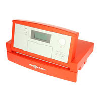
- Vitotronic 200 KW2
Manuals and User Guides for Viessmann Vitotronic 200 KW2. We have 3 Viessmann Vitotronic 200 KW2 manuals available for free PDF download: Installation And Service Instructions Manual, Operating Instructions Manual

Viessmann Vitotronic 200 KW2 Installation And Service Instructions Manual (120 pages)
Weather-compensated, digital boiler and heating circuit control unit
Brand: Viessmann
|
Category: Boiler
|
Size: 0.97 MB
Table of Contents
-
Safety Instructions
2
-
Table of Contents
4
-
System Version 1
6
-
System Version 2
7
-
System Version 3
8
-
Installation
9
-
Installation Summary of Electrical Connections
9
-
Summary of Electrical Connections
9
-
Inserting Cables and Applying Strain Relief
11
-
Changing the High Limit Safety Cut−Out Setting
12
-
Changing the Control Thermostat Setting
14
-
Inserting the Boiler Coding Card
15
-
Sensor Connection
16
-
Pump Connection
17
-
External Connection to Plug X12
18
-
Burner Connection
19
-
Mains Power Supply
21
-
Installing the Top Part of the Control Unit
22
-
Opening the Control Unit
23
-
Commissioning Controls and Display Elements
24
-
Commissioning
24
-
Controls and Display Elements
24
-
Checking the Heating Circuit Allocation
25
-
Checking the High Limit Safety Cut−Out
25
-
Changing the Display Language
25
-
Checking Outputs (Actuators) and Sensors
25
-
Matching up Coding Addresses
26
-
Adjusting Heating Curves
27
-
Service Scans Service Level Summary
30
-
Temperatures, Boiler Coding Card and Brief Scans
31
-
Scanning Operating Conditions
33
-
Scanning and Resetting the Maintenance Display
34
-
Troubleshooting Faults Which Are Displayed at the Programming Unit
36
-
Troubleshooting
36
-
Faults Which Are Displayed at the Programming Unit
36
-
Downloading Fault Codes from the Fault Memory (Fault History)
42
-
Faults Which Are Not Displayed at the Programming Unit
43
-
Function Description
46
-
Boiler Temperature Control
46
-
Heating Circuit Control
48
-
Cylinder Temperature Control
53
-
Components
56
-
Components from the Parts List
56
-
Test Button
57
-
Outside Temperature Sensor
60
-
-
Radio Clock Receiver
61
-
Flue Gas Temperature Sensor
62
-
Mixer Circuit Extension Kit
63
-
Temperature Limiter
66
-
Remote Control
67
-
Room Temperature Sensor
73
-
Control Module V
75
-
KM BUS Distributor
76
-
Boiler Coding Card
76
-
Vitoair Draught Stabiliser
77
-
Function Extension 0−10 V
78
-
Coding
79
-
Resetting Codes to the Delivered Condition
79
-
Code 1
79
-
Code 2
82
-
Overall Summary
83
-
Screed Drying Function Diagrams
102
-
Burner Switching Hysteresis
103
-
Parts List
105
-
Connection and Wiring Diagram
108
-
Specification
110
-
Settings and Equipment
111
-
Keyword Index
115
-
Applicability
120
Advertisement

Viessmann Vitotronic 200 KW2 Operating Instructions Manual (42 pages)
Heating System With Weather-Compensated Digital Boiler and Heating Circuit Control
Brand: Viessmann
|
Category: Heating System
|
Size: 0.26 MB
Table of Contents
-
Operating Instructions
1
-
Introductory Information
2
-
For Your Safety
2
-
Notice of Completion
2
-
Table of Contents
3
-
Quick Start
4
-
Where to Find the Controls
4
-
Your Heating System Is Pre-Set at the Factory
5
-
Summary of Controls and Indicators
6
-
Heating Circuit Selection before Adjustments and Scanning
9
-
Selecting the Heating Program (Summer, Winter)
10
-
Changing the Room Temperature (Day and Night Temperature)
11
-
Scanning Temperatures and Operating Conditions
12
-
Utilising the Comfort Function
13
-
Setting up the Party Mode
13
-
Activating Economy Mode
14
-
Start-Up/Shutdown
15
-
Starting the Heating System
15
-
Shutting down the Heating System
16
-
Modifying and Scanning Time Programs
17
-
General Notes
17
-
Central Heating
18
-
DHW Heating and DHW Circulation Pump
20
-
Settings
23
-
Changing the DHW Temperature
23
-
Adjusting the Economy Mode for Holiday Periods
24
-
Changing Date and Time
26
-
Selecting the Required Language
27
-
Modifying the Boiler Heating Characteristics
28
-
What to Do if
31
-
Special Displays
31
-
Diagnosis and Troubleshooting
32
-
Repairs
37
-
Energy Saving Tips
39
-
Key Word Index
40
Viessmann Vitotronic 200 KW2 Operating Instructions Manual (32 pages)
Weather-responsive indoor/outdoor, digital boiler control for heating systems with one or more heating circuits
Brand: Viessmann
|
Category: Heating System
|
Size: 1.08 MB
Table of Contents
-
Safety Instructions
2
-
Table of Contents
3
-
Tips on Getting Started
5
-
Heating Systems — Application Examples
6
-
Overview of Controls and Indicators
7
-
Vitotronic Control Unit — Factory Default Setting
9
-
Resetting Time and Date
10
-
Selecting the Heating Circuit
11
-
Altering Room Temperature
12
-
Activating and Deactivating the Heating System Activating the Heating System
14
-
Time Program for Central Heating Altering the Time Program for Central Heating
16
-
-
Altering the DHW Temperature
20
-
Altering the Time Program for the DHW Recirculation Pump
21
-
Other Settings Scanning Temperatures and Operating Status
24
-
-
Altering Settings of the Heating System
25
-
Special Displays
27
-
Emissions Test Switch
28
-
Service Instructions
30
-
Saving Energy
31
Advertisement
Advertisement
Related Products
-
Viessmann VITODENS 200 WB2B
-
Viessmann Vitosol 200-TSD2A 3m2 Series
-
Viessmann VITOSOL 200-T SD2A 2m2 Series
-
Viessmann Vitotronic 200 HO2B
-
Viessmann Vitotronic 200 HO2C
-
Viessmann Vitotronic 200 KO1B
-
Viessmann Vitotronic 200 KO2B
-
Viessmann Vitotronic 200 KW6B
-
Viessmann VITOTRONIC 300
-
Viessmann Vitotronic 200 Series
Viessmann Categories
Boiler
Toy
Control Unit
Heat Pump
Solar panel
More Viessmann Manuals
Alubox
Alubox X-treme
Alucon
Antifrogen
Aquacarbon
Aquahome
Atola
CeraCell
Condensola
Dekamatik
Divicon
EOMIX
EON
Eurola
Fauch
HoriCell
IS1500
Kospel EKCO
Kospel VSWK
Litola
Litola-CL
MatriX
Paromat
Pendola
Rondomat
RudoCell
SpiroTech
ST250
SW250
SW250LD
Trimatik
Turbomat
Ultrabox
Unit-P
Unomatik
VertiCell
VICare
Vitoair
Vitobloc 200
Vitocal
Vitocal 100-S/111-S
Vitocal 200-G
Vitocal 222-G
Vitocal 242-G
Vitocal 300
Vitocal 300-G
Vitocal 300-G Pro
Vitocal 300-G/350-G
Vitocal 300-G/W Pro
Vitocal 300-W Pro
Vitocal 333-G
Vitocal 343-G
Vitocal 350-G
Vitocal 350-G Pro
Vitocell
Vitocell 050-E
Vitocell 100
Vitocell 100-B
Vitocell 100-B/100-W
Vitocell 100-E
Vitocell 100-H
Vitocell 100-L
Vitocell 100-U
Vitocell 100-V
Vitocell 100-V/-W
Vitocell 100-W
Vitocell 100-W 100 л
Vitocell 100-W 80 л
Vitocell 120-E
Vitocell 140-E
Vitocell 160-E
Vitocell 300-B
Vitocell 300-H
Vitocell 300-V
Vitocell 300-V/-W
Vitocell 300-V/300-W
Vitocell 300-W
Vitocell 333
Vitocell 333/353
Vitocell 340-M
Vitocell 340?M/360?M
Vitocell 353
Vitocell 360-M
Vitocell-W 100
Vitocell-W 300
Vitoclima 230-S
Vitocom 100
Vitocom 200
Vitocom 300
Vitoconnect
Vitocrossal
Vitocrossal 100
Vitocrossal 200
Vitocrossal 300
Vitodens
Vitodens 050-W
Vitodens 100-W
Vitodens 111-F
Vitodens 111-W
Vitodens 141-F
Vitodens 200-W
Vitodens 200-W/300-W/333-W
Vitodens 200?W
Vitodens 222-F
Vitodens 222-W
Vitodens 222/333
Vitodens 242-F
Vitodens 300-W
Vitodens 333
Vitodens 333-F
Vitoflame 100
Vitoflame 200
Vitoflame 300
Vitogas
Vitogas 050
Vitogas 100
Vitogas 100-F
Vitogate 200
Vitogate 300
Vitola
Vitola 100
Vitola 200
Vitola-biferral
Vitola-comferral
Vitoladens
Vitoladens 300-C
Vitoladens 300-T
Vitoladens 300-W
Vitolig 150
Vitoligno 100-S
Vitomax
Vitomax 100
Vitomax 100-HS
Vitomax 100-LW
Vitomax 200
Vitomax 200-HS
Vitomax 200-HW
Vitomax 200-LW
Vitomax 300
Vitomax 300-HS
Vitomax 300-HW
Vitomax 300-LT
Vitomax 300-LW
Vitomax HS
Vitomax HW
Vitomax LCB
Vitomax LW
Vitomax-HS
Vitopend
Vitopend 050-W
Vitopend 100
Vitopend 100-W
Vitopend 100-W/200-W
Vitopend 111-W
Vitopend 200-W
Vitopend 222-W
Vitoplex
Vitoplex 100
Vitoplex 100-LS
Vitoplex 200
Vitoplex 300
Vitoplex 300 895-1750 кВт
Vitoplex/Vitorond/Vitomax
Vitoplus
Vitoradial
Vitoradial 300-T
Vitorond
Vitorond 100
Vitorond 111
Vitorond 200
Vitorondens 200-T
Vitorondens 222-F
Vitoset
Vitosoft 300
Vitosol
Vitosol 100
Vitosol 100-F
Vitosol 100-F/-FM
Vitosol 100-FM
Vitosol 141-FM
Vitosol 200
Vitosol 200-F
Vitosol 200-FM
Vitosol 200-T
Vitosol 200-TM
Vitosol 300
Vitosol 300-T
Vitosol 300-TM
Vitosolar 300-F
Vitosolic 100
Vitosolic 200
Vitotherm
Vitotrans
Vitotrans 100
Vitotrans 100-LW
Vitotrans 200
Vitotrans 200-LW
Vitotrans 222
Vitotrans 300/333
Vitotrans 300/333 1860-6600 кВт
Vitotrans 300/333 575-2000 кВт
Vitotrans 353
Vitotrol 100
Vitotrol 200-A
Vitotrol 200-E
Vitotrol 300
Vitotrol 300-A
Vitotrol 300-B
Vitotrol 300-E
Vitotron 100
Vitotronic
Vitotronic 050
Vitotronic 100
Vitotronic 100 HC1B
Vitotronic 100/200/300
Vitotronic 100/333
Vitotronic 200
Vitotronic 200 HO1B
Vitotronic 200 WPR3. Контроллер теплового насоса Vitocal
Vitotronic 200-H
Vitotronic 200. Контроллер теплового насоса Vitocal
Vitotronic 300
Vitotronic 300-K
Vitotronic 333
Vitotronic SPS
Vitovent 050-D
Vitovent 100-D
Vitovent 200-C
Vitovent 300-F
Vitovent 300-W
Vitplex
Vitоdens 200-W
Wallcon X-treme
WBS Ligna 050
ZONT H-2000/2000+
Адаптер электрических подключений
Блок управления приводом смесителя OpenTherm
Горелки
Горелки Bluetwin
Горелки Bluetwin/Unit
Датчик СО2 Vitovent 300-W
Дополнительный комплект/манометр
Комнатный термостат ST-BSOP/ST-PSOP
Контроллер KR
Контроллер SR
Контроллер Vitotrans 353
Модуль управления гелиоустановкой SDIO/SM1A
Насосные группы PAW
Нормативные показатели качества воды
Панель управления системой вентиляции
Платформа для техобслуживания котла
Примеры схем отопительных установок. Часть I
Примеры схем отопительных установок. Часть II
Примеры схем отопительных установок. Часть III
Примеры схем установок Vitosolic 100
Принадлежности
Принадлежности Vitotronic
Регулятор температуры помещения OpenTherm
Системы воздухораспределения Vitovent 300-W
Сифон Aquahome
Смесители отопительных контуров
Термическая станция водоподготовки Деаэратор
Универсальные радиаторы
Шкаф управления Vitocontrol
Шлюз WAGO MB/TCP-MB/RTU
Штиль ИнСтаб IS550
Штиль ИнСтаб SW250SL
Экономические показатели котельных установок

Summary of Content for Viessmann Vitotronic 200 KW2 Control Unit Technical Manual PDF
Certified as a component part
of Viessmann boilers only
VITOTRONIC 200 Weather-responsive indoor/outdoor, digital boiler control
for heating systems with one or more heating circuits
Vitotronic 200
Model KW2, Part No. Z001 230
For operation with modulating boiler water temperatures, and single-stage, two-stage or modulating burners
With DHW tank temperature sensor and integrated diagnostic system
Operating module with clear text LCD display
Remote control interface with room temperature sensor (optional)
Viessmann quick-connect plug-in system
Technical Data Manual
5167 888 v1.1 11/2002
Product Information/Standard Equipment/ Application
2
Product Information
The benefits at a glance:
H Easy and uniform operation: Different programming levels for system user and heating contractor.
Large, clear text LCD display format facilitates legibility of all data.
Illuminated operating mode and heating circuit keys.
Easy-to-program switching times. Digital tracking of day and week. Programmed times for domestic hot water production and recirculation pump are adjusted automatically when heating program is altered.
Plug & Work quick-connect system for automatic sensor and system recognition and adaptation.
Automatic resetting to daylight savings time.
Service interval display for demand-related maintenance.
Fuel consumption display.
H Program selection for controlled drying of concrete floor in radiant floor heating application.
H Short installation time, start-up and maintenance due to Rast-5 connector system, plug-in function modules and integrated diagnostic system.
Vitotronic 200, Model KW2
HWeather-responsive indoor/outdoor, digital boiler and heating system control: for heating systems with one boiler for heating circuits without and heating circuits with a mixing valve
for single-stage, 2-stage and modulating burners
with DHW tank temperature sensor with digital tracking of day and week with separate switching times for room heating, domestic hot water heating and recirculation pump
with integrated diagnostic system
Standard Equipment
Vitotronic 200, Model KW2 (Part No. Z001 230) with H operating module with clear text LCD display
H outdoor temperature sensor H boiler water temperature sensor H DHW tank temperature sensor H Power/Pump Module
For the heating circuit with a mixing valve, a mixing valve actuator accessory kit is required. Due to the low return water temperature of condensing boilers only 3-way mixing valves should be installed. The circulation pump with a flow check valve for DHW tank temperature control must be ordered separately.
Heating system with underfloor heating The underfloor heating circuit requires an accessory kit for operation with a mixing valve. A temperature control with high limit must be installed in the heating supply of the radiant floor heating application. The underfloor heating circuit must not be controlled by a remote control with room temperature sensor.
Application
In conjunction with the following Viessmann boilers Boiler Model and Series
Fuel Minimum boiler water temperature without low limit
with low limit (average temp.)
Oil-fired hot water heating boiler with power burner
Vitorond 200 Oil 104 F/40 C
Oil-/gas-fired hot water heating boiler with power burner
Vitola 200 Oil/Gas x
Atmospheric gas-/propane-fired hot water heating boiler
Vitogas 050, RS Series Gas 120 F/49 C
Atmospheric gas-fired hot water heating boiler
Vitogas 100, GS1 up to 240 MBH / 70 kW Vitogas 100, GS10 up to 380 MBH / 111 kW
Gas Gas
104 F/40 C 120 F/49 C
5 1 6 7 8 8 8 v1
.1
OTS STS
Structure and Operation
3
Structure and Operation
Modular structure
The complete control consists of a control base, control unit (electronic/operating modules) and a Power/Pump Module. The control unit comprises: Power on/off switch, an electronic high limit, a temperature gage and a low temperature control adjustable high limit fixed high limit TUV test switch, override switch, buttons for: holiday program party and economy modes reduced operating mode temperature domestic hot water temperature programming of heating curves for boiler water temperature and/or mixing valve circuit temperature
heating circuit selection, a selector knob for normal operating temperatures and a digital timer. Heat-demand-controlled circuit pump and burner activation, adjusting of a variable temperature limit, pump cycling, integrated diagnostic system and flue gas monitoring in connection with flue gas temperature sensor (optional) and maintenance display.
Boiler-specific functions
The Vitotronic control modulates the boiler water temperature. It gradually regulates the boiler water temperature (= the supply temperature of the direct-connected heating circuit) as well as the supply water temperature of a mixing valve circuit. The control contains an adaptive tank temperature control logic with priority switching (heat pump off, mixing valve closed). An additional function for domestic hot water heating (short-term heating to an increased temperature) can be selected.
The Vitotronic 200 is an ideal control option for your heating system with mixing valve circuit. It is the perfect solution for your underfloor heating circuit with supply and return water temperature sensor or for controlled drying of a concrete floor.
Control characteristics
Boiler circuit control unit (high temperature)
Heating circuit control with mixing valve Dead zone: 1.80 F/1 C
Adjustable high limit factory default setting: 167 F/75 C
Adjustment of the fixed high limit: 230 F/110 C adjustable to 212 F/100 C
Adjustment range of heating curve: Slope: 0.2 to 3.5 Shift: 23 F to +72 F/
13 C to +40 C High limit: 68 to 266 F/
20 to 130 C Low limit: 34 to 261 F/
1 to 127 C Differential temperature for heating circuit with mixing valve: 0 to 72 F/
0 to 40 C Adjustment range for domestic hot water setpoint temperature:
50 to 140 F/ 10 to 60 C adjustable to 50 to 203 F/ 10 to 95 C
Technical data
Rated voltage: 120 VAC Rated frequency: 60 Hz Rated current: 6 A Power consumption: 5 W Maximum ambient temperature at operation: 32 to 104 F/
0 to 40 C (in rooms and installation sites with normal ambient conditions)
when storing or transporting: 4 to +149 F/
20 to +65 C
Relay output rating in conjunction with a Power/Pump Module: Heating circuit pumps: 3 FLA/120 VAC*1
DHW tank heating circulation pump: 3 FLA/120 VAC*1
Domestic hot water recirculation pump:3 FLA/120 VAC*1
Mixing valve actuator: 0.1 FLA/120 VAC*1
Operating time approx. 2 minutes Burner plug : 2 FLA/120 VAC 2-stage burner plug *2: 0.5 FLA/120 VAC
Total: max. 12 A/120 VAC
*1Total 12 A/120 VAC *2Available only with extension module for 2-stage burner (included in boiler package).
Boiler coding card
Adapts the control to the specific boiler model being used (included in boiler package).
Connections
Sensors, burner and Power/Pump Module are connected to the back of the control unit via system plugs.
Pumps, power supply and mixing valve are connected to the Power/Pump Module via screw terminals or system plugs.
Operating unit
With digital timer Clear text LCD display Temperature and fault display Coding via display of operating unit All adjustments and basic coding information in clear text format.
5 1 6 7 8 8 8 v1
.1
Structure and Operation
4
Structure and Operation (continued)
Digital timer of operating unit
A digital timer with day and week feature, calendar, automatic resetting to daylight savings time and automatic functions for domestic hot water heating and recirculation pump. Time, day and standard switching times for room heating, domestic hot water heating and domestic hot water recirculation pump are factory preset (individually programmable), max. four time switch intervals programmmable per day. Shortest interval: 10 minutes Power reserve: 5 years
Adjusting the operating system
All operating programs feature freeze-up protection*1 for the heating system. With the program selector buttons the following can be selected: heating and domestic hot water domestic hot water only standby operation
*1 See Freeze-up Protection Function below.
Freeze-up protection function
The freeze-up protection function is activated when the outside temperature drops to +34 F/1C. The freeze-up protection function activates the circulation pumps and keeps the boiler water temperature at the reduced operation setpoint level, at a minimum temperature of approx. 68 F/20 C (for heating boilers with low limit the respective temperature will be maintained).
deactivated when the outside temperature exceeds +37 F/3 C. When the freeze-up protection function is deactivated, heating boiler and circulation pumps are turned off.
Summer economy mode
(Domestic hot water heating only, program selector switch )
The burner only activates if domestic hot water needs to be produced (as required by DHW setpoint).
Heating curve adjustment
The weather-responsive Vitotronic 200 regulates the boiler water temperature (= supply water temperature of the heating circuit without mixing valve) and the supply temperature of the heating circuit with a mixing valve. The required supply temperature for a certain room temperature depends on the heating system and the insulation of the building in question. The adjustment of both heating curves individually allows for the boiler water temperature and the supply temperature of the mixing valve circuit to be adjusted to the respective conditions.
Heating curves:
Low temperature heating system, e.g. radiant floor heating Medium temperature heating system, e.g. cast iron radiation, staple-up radiant floor heating High temperature heating system, e.g. fintube radiation, fan coils
The maximum boiler water temperature is restricted by both the adjustable high limit and the electronic maximum temperature limit. The supply water temperature cannot exceed the boiler water temperature.
Boiler water temperature sensor
Cable length 5.2 ft./1.6 m, ready to plug in. Maximum ambient temperature at operation: 32 to 266 F/
0 to 130 C when storing or transporting:
4 to +158 F/ 20 to +70 C
Outdoor temperature sensor
Installation site: North or northwest side of building 6.6 to 8.2 ft./2 to 2.5 m above ground, for multi-storey buildings mount sensor on upper half of second storey.
Connection: 2-wire cable, cable length 115 ft./ 35 m with a wire size of min. AWG 16 copper.
the cable to the outdoor sensor must not be laid near line voltage wiring (120/240 V). Maximum ambient temperature at operation, when storing or transporting: 40 to +158 F/
40 to +70 C
Domestic hot water tank temperature sensor
Cable length 19 ft./5.8 m, ready to plug in. Maximum ambient temperature at operation: 32 to 194 F/
0 to 90 C when storing or transporting:
4 to +158 F/ 20 to +70 C
5 1 6 7 8 8 8 v1
.1
Accessories
5
Accessories
Note on the room temperature sensing function (RS function)*1 when using a remote control
Due to the slow response of the underfloor heating, the RS function must not influence the underfloor heating circuit. For heating boilers with a low limit, the RS function must not influence the heating circuit without a mixing valve.
*1RS function = remote control with room sensor function
*2WS function = remote control only, no room sensor function
Vitotrol 200, Part No. 7133 378
The Vitotrol 200 remote control takes care of the room temperature setpoint adjustment at normal operation and determines the heating program from any given room. The Vitotrol 200 features illuminated heating program selector buttons as well as a party and an economy button. Fault messages are displayed on the boiler control. A remote control can be connected for each heating circuit.
WS function*2: Allows for installation at any given place in the building. RS function*1: The remote control is to be installed on an inside wall of the main living area, across from radiators, but not on shelves, in niches, in the close vicinity of doors or heat sources of any kind (e.g. direct sunlight, fireplace, TV, etc.). The installed sensor measures room temperature and, if necessary, takes corrective action and initiates fast heat-up at the outset of the heating operation (if coded). Connection: 2-wire cable, cable length max. 164 ft./50 m (also for the connection of several remote controls).
The cable must not be placed together with line voltage wiring.
Low voltage plug is included.
Rated voltage: 33 VAC Rated current: 10 mA Power consumption: 3.3 W Maximum ambient temperature at operation: 32 to 104 F/
0 to 40 C when storing or transporting: 4 to+149 F/
20 to +65 C Adjustment range of room temperature setpoint: 50 to 86 F/
10 to 30 C adjustable to 37 to 73 F/ 3 to 23 C
or 63 to 99 F/ 17 to 37 C
Adjustment of the room temperature setpoint at reduced operation takes place at the Vitotronic 200.
Vitotrol 300, Part No. 7133 382
The Vitotrol 300 remote control takes care of the room temperature setpoint adjustment at normal and reduced operation for the heating program, switching times for room heating, domestic hot water heating and the domestic hot water recirculation pump. The Vitotrol 300 features illuminated heating program selector buttons, a party and an economy button, an automatic reset function to daylight savings time, buttons for the holiday program, day of the week and time.
WS function*2: Allows for installation at any given place in the building. RS function*1: The remote control is to be installed on an inside wall of the main living area, across from radiators, but not on shelves, in niches, in the close vicinity of doors or heat sources of any kind (e.g. direct sunlight, fireplace, TV, etc.). The installed sensor measures room temperature and, if necessary, takes corrective action and initiates fast heat-up at the outset of the heating operation (if coded). Connection: 2-wire cable, cable length max. 164 ft./50 m (also for the connection of several remote controls).
The cable must not be placed together with line voltage wiring.
Low voltage plug is included.
Rated voltage: 33 VAC Rated current: 10 mA Power consumption: 3.3 W Maximum ambient temperature at operation: 32 to 104 F/
0 to 40 C when storing or transporting: 4 to +149 F/
20 to +65 C Adjustment range of room temp. setpoint: at normal operation: 50 to 86 F/
10 to 30 C adjustable to 37 to 73 F/ 3 to 23 C
or 63 to 99 F/ 17 to 37 C
at reduced operation: 37 to 99 F/ 3 to 37 C
5 1 6 7 8 8 8 v1
.1
Accessories
6
Accessories (continued)
Room temperature sensor, Part No. 7133 379
A separate room temperature sensor as an addition to the Vitotrol 200 or 300; to be used when the Vitotrol 200 or 300 remote controls cannot be placed in the main living area or in a position suitable for monitoring the room temperature. The room temperature sensor must be installed on an inside wall of the main living area, across from radiators, but not on shelves, in niches or in the close vicinity of doors or heat sources of any kind (e.g. direct sunlight, fireplace, TV, etc.). The room temperature sensor is to be connected with the Vitotrol 200 or 300. Connection: 2-wire cable with a wire diameter of AWG 16 copper.
Cable length between control unit, remote control and room temperature sensor must not exceed 115 ft./35 m.
Cable must not be placed together with line voltage wiring. Maximum ambient temperature at operation: 32 to 104 F/
0 to 40 C when storing or transporting:
4 to +149 F/ 20 to +65 C
KM-BUS Expansion Module, Part No. 7133 393
With cable (10 ft./3 m long) and low voltage plug. To connect up to 6 devices to the single KM-BUS connection of the boiler control (Vitotrol, Switching Module-V etc.).
Switching Module-V, Part No. 7133 387
With cable (10 ft./3 m long) and low voltage plug. With the Switching Module-V the following additional functions are feasible: external burner activation upon heat demand (influences burner, possible pumps and mixing valves), e.g. pool heating, ventilation equipment etc.
external disabling of burner remote switching of heating/operating program, separate for each heating circuit
external error message input output of error message (SPDT contact) connection for short-term operation of domestic hot water recirculation pump (e.g. by external button)
5 1 6 7 8 8 8 v1
.1
Accessories
7
Accessories (continued)
Mixing valve actuator accessory kit, Part No. 7133 390 consisting of a mixing valve actuator and supply temperature sensor (strap-on sensor)
Mixing valve actuator
The mixing valve actuator is to be installed directly onto the Viessmann to 2 mixing valve. The mixing valve actuator is a bi-directional, single-phase, synchronous motor with gear system and two limit switches. Rated voltage: 120 VAC Rated frequency: 60 Hz Power consumption: 4 W Maximum ambient temperature at operation: 32 to 104 F/
0 to 40 C when storing or transporting: 4 to +149 F/
0 to 65 C Torque: 3 Nm Operating time for 90: 2 minutes
Strap-on sensor (included with mixing valve actuator accessory kit), Part No. 7133 895
To determine the supply temperature of the mixing valve circuit. Installed with a strapping band. Cable length 19 ft./5 m, ready to plug in. Maximum ambient temperature at operation: 32 to 212 F/
0 to 100 C when storing or transporting: 4 to +158 F/
20 to +70 C
5 1 6 7 8 8 8 v1
.1
Viessmann Manufacturing Company Inc. 750 McMurray Road Waterloo, Ontario N2V 2G5 Canada Tel. (519) 885-6300 Fax (519) 885-0887 www.viessmann.ca mail@viessmann.ca
Viessmann Manufacturing Company (U.S.) Inc. 45 Access Road Warwick, Rhode Island 02886
Manualsnet FAQs
If you want to find out how the Vitotronic 200 Viessmann works, you can view and download the Viessmann Vitotronic 200 KW2 Control Unit Technical Manual on the Manualsnet website.
Yes, we have the Technical Manual for Viessmann Vitotronic 200 as well as other Viessmann manuals. All you need to do is to use our search bar and find the user manual that you are looking for.
The Technical Manual should include all the details that are needed to use a Viessmann Vitotronic 200. Full manuals and user guide PDFs can be downloaded from Manualsnet.com.
The best way to navigate the Viessmann Vitotronic 200 KW2 Control Unit Technical Manual is by checking the Table of Contents at the top of the page where available. This allows you to navigate a manual by jumping to the section you are looking for.
This Viessmann Vitotronic 200 KW2 Control Unit Technical Manual consists of sections like Table of Contents, to name a few. For easier navigation, use the Table of Contents in the upper left corner.
You can download Viessmann Vitotronic 200 KW2 Control Unit Technical Manual free of charge simply by clicking the “download” button in the upper right corner of any manuals page. This feature allows you to download any manual in a couple of seconds and is generally in PDF format. You can also save a manual for later by adding it to your saved documents in the user profile.
To be able to print Viessmann Vitotronic 200 KW2 Control Unit Technical Manual, simply download the document to your computer. Once downloaded, open the PDF file and print the Viessmann Vitotronic 200 KW2 Control Unit Technical Manual as you would any other document. This can usually be achieved by clicking on “File” and then “Print” from the menu bar.