-
Contents
-
Table of Contents
-
Bookmarks
Quick Links
VIESMANN
Operating instructions
for the system user
Heating system with weather-compensated control unit
Vitotronic 200, type KO1B, KO2B or KW6B
VITOTRONIC 200
Please keep safe.
5592667 GB
3/2018
Related Manuals for Viessmann Vitotronic 200 Series
Summary of Contents for Viessmann Vitotronic 200 Series
-
Page 1: Operating Instructions
VIESMANN Operating instructions for the system user Heating system with weather-compensated control unit Vitotronic 200, type KO1B, KO2B or KW6B VITOTRONIC 200 Please keep safe. 5592667 GB 3/2018…
-
Page 2: Safety Instructions
Safety instructions For your safety Please follow these safety instructions closely to prevent accidents and material losses. Safety instructions explained Danger Note This symbol warns against the risk of injury. Details identified by the word «Note» contain additional information. Please note This symbol warns against the risk of material losses and environmental pollution.
-
Page 3
Safety instructions For your safety (cont.) If you smell gas Danger Escaping gas can lead to explosions which may result in serious injury. ■ Never smoke. Prevent naked flames and sparks. Never switch lights or electrical appli- ances on or off. Close the gas shut-off valve. -
Page 4
Safety instructions For your safety (cont.) Installation room requirements Danger Please note Sealed vents result in a lack of combustion air. Incorrect ambient conditions can lead to heating This leads to incomplete combustion and the system damage and can put safe operation at formation of life threatening carbon monoxide. -
Page 5: Table Of Contents
Index Index 1. Information Symbols ………………..2. Introductory information Intended use ………………Commissioning ………………Terminology ………………. Your system is preset at the factory …………Energy saving tips …………….. Tips for more comfort …………….3. Operation Opening the control unit …………….. 10 Programming unit ………………
-
Page 6
Index Index (cont.) Setting the display brightness …………..30 Entering names for the heating circuits ……….30 Setting the preferred heating circuit for the standard menu ….31 Setting the time and date …………… 31 Language selection …………….31 Setting the temperature unit (°C/°F) …………31 Restoring factory settings ………….. -
Page 7: Symbols
Information Symbols Symbol Meaning Reference to other document containing further information Step in a diagram: The numbers correspond to the order in which the steps are carried out. Warning of material losses and environ- mental pollution Live electrical area Pay particular attention. Component must audibly click into place.
-
Page 8: Intended Use
Introductory information Intended use The appliance is intended solely for installation and Any usage beyond this must be approved by the man- operation in sealed unvented heating systems that ufacturer in each individual case. comply with EN 12828, with due attention paid to the associated installation, service and operating instruc- Incorrect usage or operation of the appliance (e.g.
-
Page 9: Energy Saving Tips
Introductory information Energy saving tips Central heating ■ Ventilation: To ventilate, close the thermostatic valves and open Standard room temperature («Set room tempera- the windows fully for a short time. ■ ture», see page 23): Roller shutters: ■ Never overheat your home. Every degree of room Close roller shutters (where installed) at dusk.
-
Page 10: Opening The Control Unit
Operation Opening the control unit The control unit may look different depending on the control unit type. Vitotronic 200, type KO1B Fig. 1 Top part of control unit with programming unit Cover flap Short operating guide on the inside of the cover Vitotronic 200, type KO2B Fig.
-
Page 11: Programming Unit
Operation Opening the control unit (cont.) Vitotronic 200, type KW6B Note You will find a short operating guide in the «Technical documentation». Fig. 3 Top part of control unit with programming unit Pushbutton for changing the angle Programming unit You can change any settings on your heating system Remote control operating instructions centrally at the programming unit of the control unit.
-
Page 12: Help» Menu
Operation Programming unit (cont.) «Help» menu Displays explanations about operation in the form of a Call up the short guide as follows: short guide. ■ If the screensaver is active (see page 14): Press . ■ From anywhere in the menu: Press repeatedly until the standard menu is shown (see page 12).
-
Page 13: Extended Menu
Operation Standard menu (cont.) Note Setting the operating program for the preferred ■ Settings for the preferred heating circuit can also be heating circuit adjusted in the extended menu (see page 13). The settings for any other connected heating circuits Press the following keys: ■…
-
Page 14
Operation How to use the controls (cont.) Screen saver 21°C 14°C Fig. 7 Current outside temperature Set room temperature 1. Press OK. This takes you to the standard menu Adjustments to the central heating can be made for (see page 12). every heating circuit. -
Page 15: How To Use The Controls
Operation How to use the controls (cont.) 21 °C 14 °C Boiler temperature 48 °C Menu Heating Solar energy Test mode Continue with Heating circuit 1 Ù Ú Htg circ. selection Ù Ú Ù Ú Party mode ê Ú Economy mode Heating circuit 2 ê…
-
Page 16: Operating Program
Operation Operating program Operating programs for central heating, DHW, frost protection Symbol Operating program Function Central heating and DHW heating «Heating and DHW» The rooms of the selected heating circuit are ■ heated in accordance with the room temperature and time program specified (see chapter «Central heating»).
-
Page 17: Time Program
Operation Time program The following explains how to input the settings for a ■ You can set the time program individually, to be the time program. The special features of each individual same, or different, for every day of the week. time program are assigned to the relevant chapters.
-
Page 18: Setting The Time Program Efficiently
Operation Time program (cont.) Setting the time program efficiently If you would like to set a different time program for just Example: You want to set a different time program for one day of the week, proceed as follows: Monday: 1.
-
Page 19
Operation Time program (cont.) Heating Mo-Fr 10 12 14 16 18 20 22 24 — -:- — — — -:- — Normal — -:- — — — -:- — Normal § Adopt with Fig. 13… -
Page 20: Starting The Heating System
Start-up/shutdown Starting the heating system Controls with the cover open For cover flap, see page 10. Vitotronic 200, type KO1B 21°C 14°C Fig. 14 Fault indicator (red) Temperature controller On indicator (green) Excess temperature reset TEST key ON/OFF switch (only for service purposes) Cover flap Vitotronic 200, type KO2B 21 °C…
-
Page 21: Shutting Down The Heating System
Start-up/shutdown Starting the heating system (cont.) Vitotronic 200, type KW6B Fig. 16 Fault indicator (red) Reset button On indicator (green) ON/OFF switch Ask your heating contractor about the following: 3. Open the shut-off valves in the oil lines (at the tank ■…
-
Page 22: Without Frost Protection Monitoring (Shutdown)
Start-up/shutdown Shutting down the heating system (cont.) Without frost protection monitoring (shutdown) 1. Turn off the ON/OFF switch (see pages 20 Information on a prolonged shutdown and 21). ■ Circulation pumps may seize up as they are not sup- plied with power. 2.
-
Page 23: Room Temperature
Central heating Room temperature Further information can be found in chapter «Terminology» in the appendix. Setting the standard room temperature for central heating Factory setting: 20 °C For all heating circuits For the preferred heating circuit Extended menu Standard menu 2.
-
Page 24: Setting The Time Program For Central Heating
Central heating Time program (cont.) Setting the time program for central heating Factory setting: One time phase from 6:00 to 22:00 h Note for every day of the week. When setting, bear in mind that your heating system requires some time to heat the rooms to the required Extended menu: temperature.
-
Page 25: Comfort Function «Party Mode
Central heating Comfort function «Party mode» Setting «Party mode» for central heating Extended menu Display in the standard menu 2. «Heating» 3. If necessary, / for the required heating circuit. 4. «Party mode» 5. Set the required room temperature for «Party mode».
-
Page 26: Cancelling «Economy Mode
Central heating Energy saving function «Economy mode» (cont.) Display in the standard menu Note The display of the set room temperature does not change. 21°C 14°C Boiler temperature 48°C Fig. 20 Cancelling «Economy mode» Automatically when the system switches to reduced ■…
-
Page 27: Cancelling Or Deleting The «Holiday Program
Central heating Energy saving function «Holiday program» (cont.) Display in the extended menu In the extended menu, you can call up the set holiday program under «Information» (see page 33). Cancelling or deleting the «Holiday program» Extended menu 3. «Holiday program» 4.
-
Page 28: Dhw Temperature
DHW heating DHW temperature Factory setting: 50 °C 3. «Set DHW temperature» 4. Set the required value. Extended menu 2. «DHW» Operating program Further information can be found in chapter «Terminology» in the appendix. Setting the operating program for DHW heating For the preferred heating circuit 3.
-
Page 29: Setting The Time Program For The Dhw Circulation Pump
DHW heating Time program (cont.) Setting the time program for the DHW circulation pump The time program for the DHW circulation pump is pre- 3. «DHW circ time prog» set to Automatic mode at the factory. In other words, 4. Set the required time phases. the DHW circulation pump operates in parallel to the To see how to set a time program, see page 17.
-
Page 30: Setting The Display Contrast
Further adjustments Setting the display contrast You can make the menu texts easier to read. To do so, 2. «Settings» adjust the contrast of the display to suit the lighting conditions in the room. 3. «Contrast» 1. Extended menu: 4. Set the required contrast. Setting the display brightness You would like to be able to read the text in the menu 2.
-
Page 31: Setting The Preferred Heating Circuit For The Standard Menu
Further adjustments Entering names for the heating circuits (cont.) The menu shows «Apartment» for «Heating circuit 2». Apartment Ù Ú Party mode 22°C Economy mode ß Set room temperature Set reduced room temp Select with Fig. 25 Setting the preferred heating circuit for the standard menu If your heating system has several heating circuits, Extended menu you can select the heating circuit to be displayed in the…
-
Page 32: Restoring Factory Settings
Further adjustments Setting the temperature unit (°C/°F) (cont.) 2. «Settings» 4. Select the temperature unit «°C» or «°F». 3. «Temperature unit» Restoring factory settings You can reset the factory settings of all modified values 3. «Standard setting» for each heating circuit separately. 4.
-
Page 33: Scanning Information
Scanning Scanning information Subject to the components connected and the settings Solar energy made, you can scan current temperatures and operat- ing conditions. In the extended menu, information is split into groups: ■ «General» ■ «Heating circuit 1» Su Mo ■…
-
Page 34
Scanning Scanning the service messages (cont.) 1. You can call up the reason for the service with OK. Note If the service cannot be carried out until a later date, Service the service message will be displayed again the follow- ing Monday. -
Page 35: Scanning Fault Messages
Scanning Scanning fault messages If any faults have occurred in your heating system, the 3. Make a note of the cause of the fault and the fault symbol flashes on the display and «Fault» is shown. code next to it on the right. In the example: «Out- The red fault indicator flashes (see chapter «Starting side t sens 18″…
-
Page 36: Emissions Test Mode
Emissions test mode Emissions test mode Emissions test mode for testing flue gas with briefly Note raised boiler water temperature. The flue gas inspector can also enable emissions test Emissions test mode should only be activated by your mode if the controls are locked out by your heating flue gas inspector during the annual inspection.
-
Page 37: Rooms Are Too Cold
What to do if… Rooms are too cold Cause Remedy The heating system is off. Turn on the ON/OFF switch (see diagrams from ■ page 20). Switch ON the mains isolator (if installed, outside the ■ boiler room). Reset the MCB in the power distribution board (main ■…
-
Page 38: Rooms Are Too Hot
What to do if… Rooms are too cold (cont.) Cause Remedy Vitoair draught stabiliser faulty. Contact your local heating contractor. Press the rotary selector on the motor and turn it past position as far as it will go. Mixer motor faulty. Adjust the mixer manually.
-
Page 39: Controls Locked Out» Is Displayed
What to do if… There is no hot water (cont.) Cause Remedy Vitoair draught stabiliser faulty. Contact your local heating contractor. Press the rotary selector on the motor and turn it past position as far as it will go. «Fault» is displayed, and the red fault indicator flashes. Call up and acknowledge the type of fault (see page 35).
-
Page 40: External Program» Is Displayed
What to do if… «External program» is displayed Cause Remedy The operating program set at the control unit was You can change the operating program. changed over by the Vitocom communication interface.
-
Page 41
If there is damage to the connecting cables or lines of the appliance or externally installed accessories, these must be replaced with special cables or lines. Only use Viessmann cables / lines as replacement. For this, notify your qualified contractor. -
Page 42: Fuel Oil Quality
Biofuels Biofuels are made from vegetable oil, e.g. sunflower or Please note rape seed oil. Biofuels can lead to damage on Viessmann oil burners. With boilers built in or after 2012, up to 10 % added bio-components (FAME) are generally allowed.
-
Page 43: Overview Of Extended Menu
Appendix Overview of extended menu Fig. 36 Calling up options under «Information» Note «Burner stage 1» Subject to the actual heating system equipment level, «Hours run» not all of the scans listed here may be available. «Burner stage 2» Where information is marked with , you can call up further details.
-
Page 44: Terminology
Appendix Calling up options under «Information» (cont.) «Date» «Time program» «Radio clock signal» «Set room temp» «Room temperature» Heating circuit 1 (HC1) «Set red. room temp» «Heating program» «Set ext. room temp» «External hook-up» ■ «Set party temp» «Holiday program» ■…
-
Page 45
Appendix Terminology (cont.) Mixer extension kit Room temperature-dependent heating mode Assembly (accessory) for controlling a heating circuit With room temperature-dependent operation a room with mixer. will be heated until the selected set room temperature See «Mixer». has been reached. A separate temperature sensor must be installed in the room for this purpose. -
Page 46
Appendix Terminology (cont.) Slope -5 -10 -15 -20 Outside temperature in °C Fig. 37 For outside temperature 14 °C: − Underfloor heating system, slope 0.2 to 0.8 Low temperature heating system, slope 0.8 to 1.6 Heating system with a boiler water temperature in excess of 75 °C, slope 1.6 to 2.0… -
Page 47
Appendix Terminology (cont.) Factory settings: Slope = 1.4 and level = 0. Outside temperature in °C Fig. 38 Changing the slope: The gradient of the heating curves changes. Changing the level: The heating curves are shifted in parallel in a verti- cal direction. -
Page 48: Information On Disposal
(Altstoff Recycling Austria AG, licence num- ber 5766). Final decommissioning and disposal of the heating system Viessmann products can be recycled. Components DE: Operating fluids (e.g. heat transfer medium) can and fluids from your heating systems are not part of be disposed of at municipal collection points.
-
Page 49: Keyword Index
Keyword index Keyword index Additives for fuel oil………… 42 Economy mode – Cancelling…………… 26 – Central heating…………25 Biofuels…………..42 – Symbol…………..12 Emissions test mode……….36 Energy saving (tips)…………. 9 Central heating Energy saving function – Factory setting…………8 – Economy mode, central heating……25 –…
-
Page 50
Keyword index Keyword index (cont.) Rooms Language selection………… 31 – Too cold…………..37 Level, heating curve……….. 24 – Too hot…………..38 Room temperature – Energy saving…………9 Maintenance……………41 – For reduced heating mode……..23 Maintenance contract……….41 – Preferred heating circuit………. 13 Menu –… -
Page 51
Keyword index Keyword index (cont.) Starting Time program – Frost protection monitoring……..21 – Central heating…………24 – Heating system…………20 – Comfort…………..9 – Standby mode…………21 – DHW circulation pump……….29 Starting the appliance……….21 – DHW heating…………28 Summertime changeover……….8 –… -
Page 52
Your contact Contact your local contractor if you have any questions about your system or wish to arrange maintenance or repair work. You can find local contractors on the internet at www.viessmann.de. Viessmann Werke GmbH & Co. KG Viessmann Limited…
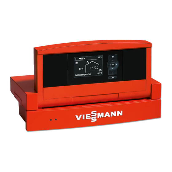
VIESSMANN Vitotronic 200 Управление котлом

Vitodens 200, программатор с Vitotronic 200, бортовое управление H01
 Vitodens 200, Vitotronic 200, схема управления H01
- Временная программа для центрального отопления
- Временная программа для приготовления горячей воды
- Праздничная программа
- Информация
- Режим ожидания
- только ГВС
- Центральное отопление и ГВС
- Регулировка нормальной комнатной температуры
- Режим энергосбережения ВКЛ/ВЫКЛ
- Режим вечеринки ВКЛ/ВЫКЛ
- Заводская установка по умолчанию
- Кнопка подтверждения
- Кнопки регулировки
- Температура ГВС
- Функция проверки выбросов (только для фирм, занимающихся отоплением) P Пониженная комнатная температура
- Дата / время
 ПРИМЕЧАНИЕ: Система управления будет отображать температуру котла, если она не находится в режиме программирования или в режиме неисправности.
Символы дисплея
Эти символы не отображаются постоянно, а появляются в зависимости от типа системы и рабочего состояния.
- Риск заморозков
- Центральное отопление с нормальной комнатной температурой Центральное отопление с пониженной комнатной температурой Защита от замерзания Насос отопительного контура ВКЛ Нормальный насос отопительного контура ВКЛ
- Пониженный насос отопительного контура ВКЛ.
- Смесительный клапан открыт
- Смесительный клапан закрыт
- Операция ручного управления
- автоматическая работа
- Нагрев ГВС включен
- Насос ГВС ВКЛЮЧЕН, нагрев ГВС включен Нагрев ГВС через систему солнечного нагрева Горелка ВКЛЮЧЕНА
- Дисплей настройки времени
- Тест выбросов включен
- Индикатор неисправности
- Номер отопительного контура
- Сканирование часов работы, сканирование количества запусков горелки и потребления
ПРИМЕЧАНИЕ: Чтобы отрегулировать контрастность дисплея, нажмите и удерживайте и используйте кнопки для нужной настройки.
Сообщения об ошибках при первом запуске
При первом запуске на дисплее может появиться слово Storung (неисправность). Если ошибок нет, перейдите к разделу «Установка времени и даты», в противном случае выполните следующие действия:
- Нажмите информационную кнопку
 .
. - Считайте и запишите код и номер неисправности.
- Нажмите .ok Квиттирен? Ja (подтвердить? да) отображается.
- Чтобы подтвердить ошибку, нажмите ок.
ПРИМЕЧАНИЕ: Неисправности могут быть исправлены после завершения всего программирования и кодирования.
 Установка времени и даты
При первом включении будет мигать слово Uhrzeit (время). Чтобы установить время и дату, выполните следующие действия:
- Нажмите
 кнопки для установки текущего времени (формат 24:00).
 - Чтобы подтвердить время, нажмите ок . Дата начнет мигать.
- Нажмитекнопки для установки текущей даты (в формате ДД/ММ/ГГ).
- Для подтверждения даты нажмите ок.
ПРИМЕЧАНИЕ: Если система оснащена блоками дистанционного управления (Vitocontrol 300), время и дату можно установить в каждом удаленном месте. Чтобы изменить время и дату в любое время и в любом месте, нажмите кнопку и выполните ту же процедуру, что показана выше.  Изменение языка
Язык управления по умолчанию — немецкий. Чтобы установить английский язык управления, выполните следующие действия:
- Нажмите информационную кнопку .
- Может отображаться Heizkreis Wahlen (выбрать отопительный контур), при необходимости выберите отопительный контур и нажмитеснова.
- Нажимайте кнопки и прокручивайте меню до тех пор, пока на экране не отобразится английский язык.
- Нажмите кнопку ОК, чтобы принять.
ПРИМЕЧАНИЕ: Если система оснащена блоками дистанционного управления (Vitocontrol 300), язык необходимо настроить в каждом удаленном месте. Выполните ту же процедуру, что и на рисунке, и выберите нужный язык.
Изменение отображения температуры с oC на oF  Для изменения отображения температуры с oC на oF вызовите уровень кодирования 2.
- Нажмите
 и
и  кнопки одновременно и удерживайте в течение 2 секунд и подтвердите с помощью ок .
 - На дисплее появится 00: 0 (00: мигает).
- Нажмите кнопки для установки от 00: до 88:
- Нажмите ок, (будет мигать только 0).
- Нажмите кнопки, чтобы установить от 0 до 1.
- Нажмите ок , (будет отображено Принято).
- Чтобы выйти из уровня кодирования 2, нажмите и кнопки одновременно на 1 секунду.
ПРИМЕЧАНИЕ: Дисплеи меняются в удаленных местах.
Установочная температура, пониженная температура в помещении и температура ГВС
Если система оснащена блоками дистанционного управления, настройки температуры для помещения, уменьшенного помещения и ГВС должны быть установлены на каждом месте управления.
- Для нормальной комнатной температуры (по умолчанию 68oF) нажмите кнопку, затем поверните диск
 для выбора желаемой температуры.
 - Для пониженной комнатной температуры (по умолчанию 37°F) нажмите
 затем нажмите кнопку кнопки для выбора желаемой температуры.
 - Нажмите ок, чтобы установить температуру.
- Для температуры ГВС (по умолчанию 122°F) нажмите затем нажмите кнопку кнопки для выбора желаемой температуры.
- Нажмите ок, чтобы установить температуру.
 Тест реле, проверка датчика температуры и рабочие условия Тест ScanRelay
- Нажмите и ок одновременно примерно на 2 секунды.
- Выберите релейные выходы с помощью кнопки.
- Для выхода из тестового режима нажмите .
Темп. проверка датчиков и сканирование рабочих условий - Нажмите кнопку.
- При необходимости выберите отопительный контур и нажмите кнопку снова.
- Отсканируйте необходимую информацию с помощью кнопки.
- Чтобы выйти, нажмите.
ПРИМЕЧАНИЕ: Дополнительную информацию и списки значений для проверки реле, проверки датчиков температуры и рабочих условий см. в инструкциях по эксплуатации, установке и обслуживанию, прилагаемых к системе. 
Уровень кодирования 1 и 2
Вызов уровня кодирования 1 (базовое программирование)
- Нажмите и одновременно примерно на 2 секунды.
- Выберите нужный кодовый адрес с помощью кнопки, адрес будет мигать, подтвердите с помощью , значение будет мигать.
- Чтобы изменить значение, нажмите кнопку кнопки, после завершения подтвердите с помощью ok .
- Вызов дополнительных кодовых адресов с помощью кнопки.
- Чтобы выйти из уровня кодирования 1, нажмите и одновременно примерно на 1 секунду.
Сброс кодов до заводских настроек
- Нажмите и одновременно примерно на 2 секунды.
- Нажмите кнопку заводских настроек по умолчанию и подтвердите «Базовые настройки? Да с ок.
Вызов уровня кодирования 2 (детальное программирование)
- Нажмите ок и одновременно примерно на 2 секунды и подтвердите с помощью .
- Выберите нужный кодовый адрес с помощью кнопок, адрес будет мигать, подтвердите с помощью , значение будет мигать.
- Чтобы изменить значение, нажмите кнопку кнопки, после завершения подтвердите с помощью .
- Вызов дополнительных кодовых адресов с помощью кнопки.
- Чтобы выйти из уровня кодирования 2, одновременно нажмите и и удерживайте примерно 1 секунду.
ПРИМЕЧАНИЕ: Уровень кодирования 2 содержит всю программную информацию уровня кодирования 1.
ПРИМЕЧАНИЕ: Перечни уровней кодирования 1 и 2 см. в инструкциях по установке и обслуживанию, прилагаемых к системе.
УСТРАНЕНИЕ НЕПОЛАДОК
Вызов квитированных сообщений об ошибках
- Нажмите нормально в течение приблизительно 2 секунд.
- С помощью кнопок выберите сообщение о подтвержденном коде неисправности.
- Устраните каждую неисправность в соответствии с разделом «Поиск и устранение неисправностей» Инструкций по установке и обслуживанию.
- После устранения каждой неисправности нажмите сброс для подтверждения.
Извлечение кодов неисправностей из истории неисправностей
- Нажмите и ок одновременно примерно на 2 секунды.
- Выберите сообщение с сохраненным кодом неисправности с помощью кнопки.
- Все коды неисправностей можно удалить, нажав . Удалить? Да, появится, нажмите да или нет.
- Чтобы завершить сканирование неисправностей, нажмите ОК.
Дополнительные функции
- Программа времени нагрева
- Программа времени горячей воды для бытовых нужд
- Временная программа рециркуляционного насоса ГВС
- Праздничная программа
- Наклон кривой отопления (находится в кодировке 2)
- Сдвиг кривой отопления (находится в кодировке 2)
- Режим ожидания
- Только ГВС
- Режим вечеринки
- Энергосберегающий режим
- Проверка участника (только на LON-устройствах)
- Последовательность котла (при каскадном управлении)
- Каскадное управление
- Запуск/остановка только нагрева ГВС
- Запуск/останов только системы отопления
- Пуск/останов ГВС и системы отопления
- Пульты управления
ПРИМЕЧАНИЕ: Информацию о доступе к дополнительным функциям см. в инструкциях по эксплуатации, установке и обслуживанию, прилагаемых к системе.
Документы / Ресурсы