- Manuals
- Brands
- Webasto Manuals
- Heater
- Air Top Evo 40
- Installation instructions manual
-
Contents
-
Table of Contents
-
Troubleshooting
-
Bookmarks
Quick Links
Installation Instructions
Air heaters
Air Top Evo 40 | Air Top Evo 55
English
Related Manuals for Webasto Air Top Evo 40
Summary of Contents for Webasto Air Top Evo 40
-
Page 1: Installation Instructions
Installation Instructions Air heaters Air Top Evo 40 | Air Top Evo 55 English…
-
Page 2: Table Of Contents
10.4 Starting up system with two units Removing fuel from vehicle fuel tank 10.5 Product registration Removing fuel from separate fuel tank Troubleshooting Fuel line 11.1 Error code output Fuel pump Fuel filter Sticker Air Top Evo 40 | Air Top Evo 55…
-
Page 3
Technical data 12.1 Heater Annex 13.1 Drilling template: heater 13.2 Legends to the wiring diagrams 13.3 Wiring diagrams Air Top Evo 40 | Air Top Evo 55… -
Page 4: About This Document
Warranty and liability These installation instructions are an integral part of the product Webasto shall not assume liability for defects or damage that are and contain all the information required to ensure correct and the result of the installation and operating instructions being dis- safe installation.
-
Page 5: Safety
Installation of heater in ADR vehicles: Comply with ADR gui- delines. Cables damaged on sharp edges can cause short-circuits Fit protectors on sharp edges. Danger of lacerations on sharp edges Fit protectors on sharp edges. Air Top Evo 40 | Air Top Evo 55…
-
Page 6: Heater
Fig. 01: Installation example (installation conditions dependent on vehicle type) Control element Fuel pump Heater Exhaust silencer (accessory) Fuse Combustion air intake line Fuel standpipe Combustion air intake silencer (accessory) Fuel filter (accessory) 10 Maximum permissible fording level Air Top Evo 40 | Air Top Evo 55…
-
Page 7: Installation Location Requirements
■ The installation location is protected from mechanical damage. ■ Persons cannot come in contact with hot surfaces. Install con- tact guard if necessary. ■ Heat-sensitive parts are protected from high temperatures. Ins- tall heat shield if necessary. Air Top Evo 40 | Air Top Evo 55…
-
Page 8: Heater Dimensions
Cable outlet (optionally on right or left) Space requirements for cold air inlet Hot air outlet Space requirements for removing heater Exhaust gas outlet Heater is supported only by the base Fuel inlet Combustion air inlet Air Top Evo 40 | Air Top Evo 55…
-
Page 9: Installation Position
Make sure that the installation location satisfies the require- ments. Ensure the correct installation position. Comply with vehicle manufacturer’s instructions. Unevenness >1 mm: Flatten out support surface. Drill holes with the aid of the drilling template (see „13 Annex“). Air Top Evo 40 | Air Top Evo 55…
-
Page 10: Cold And Hot Air System
Risk of injury by rotating fan wheel heater or the hot air from the vehicle heating sys- Lacerations tem is not drawn in directly. If no cold air duct is used: Install mesh guard over intake. Air Top Evo 40 | Air Top Evo 55…
-
Page 11: External Temperature Sensor
■ The installation location is outside the range of other heat sour- ces (e.g. vehicle heating system). ■ The installation location is not in direct sunlight (e.g. not on the dashboard). ■ The air can circulate unhindered (e.g. not covered by curtains). Air Top Evo 40 | Air Top Evo 55…
-
Page 12: Fuel Supply
(bar) Fuel take-off from swirl pot: – Make sure that the swirl pot is not completely emptied. Removing fuel from vehicle fuel tank The Webasto fuel extractor can be installed on the fuel delivery unit. p (bar) CAUTION Risk of fire by fuel escaping from leaking fuel…
-
Page 13: Removing Fuel From Separate Fuel Tank
Make sure that the connections are tight. Minimum distance 10 mm Installing fuel lines Make sure that the intake pipe of the Webasto fuel extractor cannot impair operation of the vehicle’s fuel delivery unit with Malfunctions caused by gas bubbles and high fuel fuel gauge in any operating mode.
-
Page 14: Fuel Pump
Enter fuel filter in the vehicle’s service booklet. Installation position of fuel filter Webasto recommends installing the fuel filter in ver- tical position. Vertical installation improves bleeding of the fuel filter. Air Top Evo 40 | Air Top Evo 55…
-
Page 15: Sticker
(arrow). Sticker Fig. 14: Sticker «Switch Off Heater Before Refuelling» Affix the sticker «Switch Off Heater Before Refuelling» (included in scope of delivery) in area of fuel filler neck. Air Top Evo 40 | Air Top Evo 55…
-
Page 16: Combustion Air System
Damage caused by confusing the exhaust line with the combustion air intake line Damage to fuel pump cable caused by sharp end of pipe Connect exhaust line only to the exhaust outlet coupling. Air Top Evo 40 | Air Top Evo 55…
-
Page 17: Exhaust System
90° Install exhaust line continually falling from heater so that con- ±10° to the ground. densation can drain off. If exhaust line cannot be installed continually falling: Air Top Evo 40 | Air Top Evo 55…
-
Page 18: Exhaust Silencer
Maintain adequate distance from heat-sensitive parts. A heat shield can be fitted. Install exhaust silencer such that condensation can drain off through the condensation drain hole in the exhaust silencer. Air Top Evo 40 | Air Top Evo 55…
-
Page 19: Electrical Connection
Drill holes according to the control element installation instruc- tions. Connect plug to control element according to the labelling on the heater wiring harness. You will find further information in the installation instructions for the control element. Air Top Evo 40 | Air Top Evo 55…
-
Page 20: Installation As System With Two Heaters
(see „13 Annex“). Connect the control element to the master heater. Connect the external temperature sensor to the master heater. Switch on voltage supply. Carry out initial operation procedure for both heaters. Air Top Evo 40 | Air Top Evo 55…
-
Page 21: Initial Operation
10.2 Checking operation with Webasto Thermo Test PC Diagnosis Correct operation of the heater can be checked with the Webasto Thermo Test PC Diagnosis. Check heater in stable operation for approx. 15 minutes with the diagnosis monitoring function.
-
Page 22: Troubleshooting
If an error occurs, the unit outputs a fault code via the control ele- ment. You will find further information in the operating ins- tructions and in the heater workshop manual. Air Top Evo 40 | Air Top Evo 55…
-
Page 23: Technical Data
The standard tolerances of ±10 % for heaters shall apply if no limits are specified. The values in brackets apply for the extended heating capacity (boost function) that is activated temporarily during each start. Air Top Evo 40 | Air Top Evo 55…
-
Page 24: Annex
13 Annex 13.1 Drilling template: heater Ø 7.5 Ø 29 Ø 28 Ø 7.5 Ø 7.5 Fig. 25: Drilling template: heater Air Top Evo 40 | Air Top Evo 55…
-
Page 25: Legends To The Wiring Diagrams
Plug connection Wiring harness connection DP42 orange Plug connection Wiring harness connection DP42 Fuel pump DP42 black auxiliary drive / pumping device violet Solenoid valve / pump (max. 500 mA) white Air Top Evo 40 | Air Top Evo 55…
-
Page 26
Switch-on signal (ON/OFF) Multifunction (ventilation, boost, ECO) with control element MC02, only Boost activation for ambulance units Setpoint sensor – CO2 setting Not used Setpoint sensor + W-bus (Webasto Thermo Test PC-Diagnosis connection) Air Top Evo 40 | Air Top Evo 55… -
Page 27: Wiring Diagrams
Air Top Evo 40 and Air Top Evo 55, 12 V/24 V with rotary selector control element and vehicle blower Fig. 26: Wiring diagram — Air Top Evo 40 and Air Top Evo 55, 12 V/24 V with rotary selector control element and vehicle blower…
-
Page 28
Air Top Evo 40 and Air Top Evo 55, 24 V ADR operation with rotary selector control element Fig. 27: Wiring diagram — Air Top Evo 40 and Air Top Evo 55, 24 V ADR operation with rotary selector control element… -
Page 29
0,5 mm² ge ws sw ge Fig. 28: Wiring diagram — Air Top Evo 40 and Air Top Evo 55, 12 V/24 V with Combi timer control element and electrical battery disconnector Air Top Evo 40 | Air Top Evo 55… -
Page 30
Air Top Evo 40 and Air Top Evo 55, 24 V with SmartControl / MultiControl control element Fig. 29: Wiring diagram — Air Top Evo 40 and Air Top Evo 55, 24 V with SmartControl / MultiControl control element Air Top Evo 40 | Air Top Evo 55… -
Page 31
0,5mm² X9 (b) Fig. 30: Wiring diagram — Air Top Evo 40 and Air Top Evo 55, 12 V/24 V with Multi Control (MC04) control element and vehicle blower (wiring harness: optional) Air Top Evo 40 | Air Top Evo 55… -
Page 32
Air Top Evo 40 and Air Top Evo 55, 24 V with SmartControl / MultiControl Unibox control element Fig. 31: Wiring diagram — Air Top Evo 40 and Air Top Evo 55, 24 V with SmartControl / MultiControl Unibox control element… -
Page 33
Air Top Evo 40 and Air Top Evo 55, 24 V ADR operation with SmartControl control element Fig. 32: Wiring diagram — Air Top Evo 40 and Air Top Evo 55, 24 V ADR operation with SmartControl control element Air Top Evo 40 | Air Top Evo 55… -
Page 34
0,5mm² br 0,5mm² X9(a) rt 0,5mm² sw 0,5mm² bl 0,5mm² ws 0,5mm² Fig. 33: Wiring diagram — Air Top Evo 40 and Air Top Evo 55, 12 V/24 V, «Master heater“ Air Top Evo 40 | Air Top Evo 55… -
Page 35
Air Top Evo 40 and Air Top Evo 55, 12 V/24 V, «Slave heater“ Fig. 34: Wiring diagram — Air Top Evo 40 and Air Top Evo 55, 12 V/24 V, «Slave heater“ Air Top Evo 40 | Air Top Evo 55… -
Page 36
In multilingual versions the German language is binding. The telephone number of the respective country can be obtained from the Webasto service point flyer or the homepage of your respective Webasto country representative. Webasto Thermo & Comfort SE Postfach 1410…
info@112auto.ru
+7 (812) 927-0-112
Главная страница
Моя корзина
Оформить заказ
Санкт-Петербург:
8(812)927-0-112
Продажа отопителей: Webasto, Eberspacher, Планар и запасных частей.
Интернет магазин по продаже отопительного оборудования Webasto, Eberspacher, Атлант, Планар, Lunfei, Лунфей.
- Manuals
- Brands
- Webasto Manuals
- Heater
- Air Top Evo 40
- Workshop manual
-
Contents
-
Table of Contents
-
Troubleshooting
-
Bookmarks
Quick Links
Air Heaters
Visit www.butlertechnik.com for more technical information and downloads.
www.butlertechnik.com
Workshop Manual
Air Top Evo 40
Air Top Evo 55
Air Top Evo 40 B / Air Top Evo 55 B
(Petrol)
Air Top Evo 40 D / Air Top Evo 55 D
(Diesel/PME)
Related Manuals for Webasto Air Top Evo 40
Summary of Contents for Webasto Air Top Evo 40
-
Page 1
Visit www.butlertechnik.com for more technical information and downloads. Air Heaters Workshop Manual Air Top Evo 40 Air Top Evo 55 Air Top Evo 40 B / Air Top Evo 55 B (Petrol) Air Top Evo 40 D / Air Top Evo 55 D (Diesel/PME) www.butlertechnik.com… -
Page 2
Only genuine Webasto parts may be used. See also Webasto air and water heaters accessories catalogue. NEVER try to install or repair Webasto heating or cooling systems if you have not completed a Webasto training course, you do not have the necessary technical skills and you do not have the technical documentation, tools and equipment available to ensure that you can complete the installation and repair work properly. -
Page 3: Table Of Contents
Visit www.butlertechnik.com for more technical information and downloads. Air Top Evo 40 / Air Top Evo 55 Table of Contents Introduction …………..101 Contents and purpose .
-
Page 4
Visit www.butlertechnik.com for more technical information and downloads. Air Top Evo 40 / Air Top Evo 55 Functional Checks …………..601 General information . -
Page 5
Fig. 707 Wiring diagram for Air Top Evo 40 and Air Top Evo 55 «Slave heater», 12 V/24 V ….704 Fig. 708 Connection diagram fir Air Top Evo 40 and Air Top Evo 55 with 1531 combination timer . -
Page 6: Statutory Regulations And Safety Instructions
Any special safety regulations relevant to this instruction manual will be highlighted in the relevant sections or text 1.1.1 Use of air heaters passages of the procedures. The Webasto Air Top Evo 40 / Air Top Evo 55 air heaters are 1.4.1 Statutory regulations governing used installation –…
-
Page 7: Introduction
The fuel lines may not make direct contact to the exhaust pipe and must be thermally insulated if necessary, as other- When installed in the vehicle interior, the Air Top Evo 40 / Air wise there is a fire danger.
-
Page 8
Visit www.butlertechnik.com for more technical information and downloads. Introduction Air Top Evo 40 / Air Top Evo 55 NOTE Liability claims If damage to or leaks in the fuel line are determined, the Failure to follow the installation instructions and the notes… -
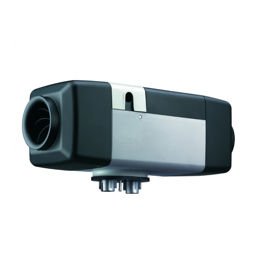
Page 9: Fig. 201 Air Top Evo 40 / Air Top Evo 55 Air Heater
Visit www.butlertechnik.com for more technical information and downloads. Air Top Evo 40 / Air Top Evo 55 General Description General Description The Air Top Evo 40 / Air Top Evo 55 air heater designed ac- cording to the evaporator principle mainly consists of the fol- lowing: –…
-
Page 10: Fig. 204
Visit www.butlertechnik.com for more technical information and downloads. General Description Air Top Evo 40 / Air Top Evo 55 Heat exchanger The heat generated by combustion in the heat exchanger is given off to the cold air transported by the heating air fan.
-
Page 11: Fig. 208 Exhaust Temperature Sensor
Fig. 208 Exhaust temperature sensor The Air Top Evo 40 / Air Top Evo 55 heaters must be operated with the DP 42 fuel pump. Blow-out temperature sensor The blow-out temperature sensor measures the tempera- tures in the fin area of the heat exchanger during the entire heater operation.
-
Page 12: Function Description
When the heater is switched on the operating display will be lit and the glow plug will be switched on (cycled). The drive Air Top Evo 40 / Air Top Evo 55 can be activated either with motor with the combustion and heating air fan is adjusted to suitable control elements, e.g.
-
Page 13: Control Mode
This ensures controlled combustion oper- 3.7.1 System design ation. The Air Top Evo 40 D and Air Top Evo 55 D heaters (diesel) Control mode can be designed as a system with 2 heaters. In the control mode, the drive motor speed and the fuel Here Unit 1 is defined as the master heater and Unit 2 as the pump quantity are dependent on the heating capacity.
-
Page 14: Fault Switch-Off
Visit www.butlertechnik.com for more technical information and downloads. Function Description Air Top Evo 40 / Air Top Evo 55 After an ADR switch-off, the control unit is in the «ADR lock- out» position. For repeat start-up, the control element must be set to «OFF»…
-
Page 15: Reset A Fault Switch-Off
Visit www.butlertechnik.com for more technical information and downloads. Air Top Evo 40 / Air Top Evo 55 Function Description 3.10.2 Reset a fault switch-off Cancel permanent heater lock-out Only for “OE” heater variants which are integrated in the ve- Switch on heater hicle bus system.
-
Page 16: Fig. 401
The Air Top Evo 40 D / Air Top Evo 55 D unit is also approved for operation with PME (bio-diesel) which complies with the * not for ADR standard DIN EN 14214.
-
Page 17: Fig. 402 Setpoint Values For Resistance Values Of Components
Visit www.butlertechnik.com for more technical information and downloads. Air Top Evo 40 / Air Top Evo 55 Technical Data Setpoint values: 12 V 24 V Glow plug At 25 °C No marking Green marking Test current: < 5 mA 0.190 — 0.250 ohms 0.740 — 0.940 ohms…
-
Page 18: Troubleshooting
Visit www.butlertechnik.com for more technical information and downloads. Troubleshooting Air Top Evo 40 / Air Top Evo 55 Troubleshooting General information • Corrosion on connector • Loose connection on connector • Poor crimp contacts on plugs If a malfunction occurs, a flashing code is displayed on the •…
-
Page 19: Fig. 502 Error Symptoms During Function
Visit www.butlertechnik.com for more technical information and downloads. Air Top Evo 40 / Air Top Evo 55 Troubleshooting Error symptoms during function The following table (Fig. 502) lists the possible error symp- NOTE toms in the order in which they may occur during operation.
-
Page 20: Fig. 503 Faults And Error Remedies
Visit www.butlertechnik.com for more technical information and downloads. Troubleshooting Air Top Evo 40 / Air Top Evo 55 Fault code displayed in control element If serious malfunctions, such as overheating or failure to start, In case of equipment with a rotary selector or an Air Top Evo…
-
Page 21
Visit www.butlertechnik.com for more technical information and downloads. Air Top Evo 40 / Air Top Evo 55 Troubleshooting Fault Fault (group) Additional information during PC di- Troubleshooting code agnostic F 05 Not available F 06 Not available F 07 Fuel pump defective… -
Page 22: Maintenance Display In Control Element
Visit www.butlertechnik.com for more technical information and downloads. Troubleshooting Air Top Evo 40 / Air Top Evo 55 Maintenance display in control element The maintenance signal is displayed when an operating period of more than 3,000 operating hours has been reached or the heater is in a restricted operating mode.
-
Page 23: Fig. 601 Components Required For Operating A Heater
Visit www.butlertechnik.com for more technical information and downloads. Air Top Evo 40 / Air Top Evo 55 Functional Checks Functional Checks General information The following schematic diagram shows the components necessary for operating a heater. This section describes the tests conducted on the heater Application-specific interfaces must be taken into account.
-
Page 24: Fig. 602 Heater Test Bench
Visit www.butlertechnik.com for more technical information and downloads. Functional Checks Air Top Evo 40 / Air Top Evo 55 Diesel units: 3. Adjust the CO value by turning the adjustment knob. Turning it anticlockwise will reduce the CO value, whilst turning it clockwise will increase it.
-
Page 25: Tests Of Individual Components
Visit www.butlertechnik.com for more technical information and downloads. Air Top Evo 40 / Air Top Evo 55 Functional Checks Tests of individual components IMPORTANT For function tests always disconnect the connection between the control unit and the component to be tested.
-
Page 26: Burner Component Assembly
Visit www.butlertechnik.com for more technical information and downloads. Functional Checks Air Top Evo 40 / Air Top Evo 55 6.4.1 Burner component assembly See Fig. 907, Item 3 and Item 7 Procedure Test or meas- Visual Burner assembly uring equip-…
-
Page 27: Resistance Test Of Exhaust Temperature Sensor
Visit www.butlertechnik.com for more technical information and downloads. Air Top Evo 40 / Air Top Evo 55 Functional Checks 6.4.2 Resistance test of exhaust temperature sensor See Fig. 907, Item 10. During the test with a digital multimeter, the exhaust temper- ature sensor is to have the following values: Resistance at 20 °C:…
-
Page 28: Heating Air Fan Component
Visit www.butlertechnik.com for more technical information and downloads. Functional Checks Air Top Evo 40 / Air Top Evo 55 6.4.3 Heating air fan component See Fig. 903, Item 1 Procedure Test or meas- Visual uring equip- Heating air fan ment Visual inspection –…
-
Page 29
Visit www.butlertechnik.com for more technical information and downloads. Air Top Evo 40 / Air Top Evo 55 Functional Checks Procedure Test or meas- Visual uring equip- Glow plug ment Contacts detached? Visual inspection Cables damaged? Visual inspection Ceramic broken? Visual inspection… -
Page 30: Fig. 203 Drive Unit
Visit www.butlertechnik.com for more technical information and downloads. Functional Checks Air Top Evo 40 / Air Top Evo 55 6.4.5 Drive unit component See Fig. 903, Item 2 Procedure Test or meas- Visual uring equip- Drive unit ment Externally damaged?
-
Page 31: Blow-Out Temperature Sensor Component
Visit www.butlertechnik.com for more technical information and downloads. Air Top Evo 40 / Air Top Evo 55 Functional Checks 6.4.6 Blow-out temperature sensor component See Fig. 903, Item 9 During the resistance test with a digital multimeter, the blow- out temperature sensor must have values in accordance with the following chart: Temperature in °C…
-
Page 32: Control Unit Component
Visit www.butlertechnik.com for more technical information and downloads. Functional Checks Air Top Evo 40 / Air Top Evo 55 6.4.7 Control unit component See Fig. 701 and Fig. 903, Item 4 Procedure Test or meas- Visual uring equip- Control unit…
-
Page 33: Heater Component
Visit www.butlertechnik.com for more technical information and downloads. Air Top Evo 40 / Air Top Evo 55 Functional Checks 6.4.8 Heater component Description Procedure Test or meas- uring equip- Complete heater ment Remove upper shell from heater and pull component…
-
Page 34
Visit www.butlertechnik.com for more technical information and downloads. Functional Checks Air Top Evo 40 / Air Top Evo 55 Description Procedure Test or measuring equipment Installation of component in unit => short circuit to metal parts (heat exchanger Replace compo-… -
Page 35
Visit www.butlertechnik.com for more technical information and downloads. Air Top Evo 40 / Air Top Evo 55 Functional Checks Description Procedure Test or measur- ing equipment Reinstallation of control unit in heater to be tested value Function test – Heater test… -
Page 36: Fig. 701 Ccombinationnector Assignment Combination Ccombinationtrol Unit
Fig. 708 shows the schematic connection of the combination timer. The Air Top Evo 40 / Air Top Evo 55 heaters can be operated Fig. 709 shows the schematic connection of the Air Top Evo with the rotary selector, a combination timer or the Air Top Multi Control (MC04) control element.
-
Page 37: Fig. 702 Wiring Diagram For Air Top Evo 40 And Air Top Evo 55, 12 V/24 V With Rotary Selector And Vehicle Fan
Wiring Diagrams Fig. 702 Wiring diagram for Air Top Evo 40 and Air Top Evo 55, 12 V/24 V with rotary selector and vehicle fan Fig. 703 Wiring diagram for Air Top Evo 40 and Air Top Evo 55, 24 V for ADR operation with rotary selector…
-
Page 38: Fig. 705 Wiring Diagram For Air Top Evo 40 And Air Top Evo 55, 12 V/24 V With Air Top Evo
Wiring diagram for Air Top Evo 40 and Air Top Evo 55, 12 V/24 V with 1531 combination timer and electr. battery isolation switch Fig. 705 Wiring diagram for Air Top Evo 40 and Air Top Evo 55, 12 V/24 V with Air Top Evo MultiComfort (MC04) control element. Wiring harness available as an option. www.butlertechnik.com…
-
Page 39: Fig. 706 Wiring Diagram For Air Top Evo 40 And Air Top Evo 55 «Master Heater», 12 V/24 V With Rotary Selector
X9(a) rt 0,5mm² sw 0,5mm² bl 0,5mm² ws 0,5mm² Fig. 706 Wiring diagram for Air Top Evo 40 and Air Top Evo 55 «Master heater», 12 V/24 V with rotary selector X1/X2 X3/X4/X5/X6/X8 rt 0,5mm² ge/rt 0,5mm² ge 0,5mm² br 0,5mm²…
-
Page 40: Fig. 708 Connection Diagram Fir Air Top Evo 40 And Air Top Evo 55 With 1531 Combination Timer
Wiring Diagrams Air Top Evo 40 / Air Top Evo 55 Fig. 708 Connection diagram fir Air Top Evo 40 and Air Top Evo 55 with 1531 combination timer 1. 1531 combination timer 4. red: Terminal 30 2. grey: Terminal 58 5.
-
Page 41
Visit www.butlertechnik.com for more technical information and downloads. Air Top Evo 40 / Air Top Evo 55 Wiring Diagrams Legend for wiring diagrams Cable cross-sections Cable colours < 7.5 m 7.5 — 15 m Abbreviation Colour 0.75 mm 1.0 mm… -
Page 42
Visit www.butlertechnik.com for more technical information and downloads. Wiring Diagrams Air Top Evo 40 / Air Top Evo 55 Note numbers (1) With plus from Terminal 15/75 to Connection 10: Continuous operation with immediate heating as long as ignition is switched on. -
Page 43: Work On Heater
The operation of the heater without a cover for the control unit is not permissible and will result in overheating. As an alternative, the Air Top Evo 40 / Air Top Evo 55 heaters can be operated with an external temperature sensor (see Servicing work Section 9.1.2).
-
Page 44: Fig. 801
Fig. 801). 20 cm to the body parts is maintained. The Air Top Evo 40 / Air Top Evo 55 heaters may only be op- The heater automatically checks the internal temperature in- erated with the DP 42 fuel pump.
-
Page 45: Fig. 802 Fuel Filter, Installation Position And Flow Direction
If soiled combustion air is to be expected, a combustion air If the exhaust line is 2 m or more, insulated exhaust lines must filter can be installed (only Air Top Evo 40 D /Air Top Evo be used (to prevent the temperature falling below the dew 55 D).
-
Page 46: Fig. 804 Permissible Installation Position Of Exhaust Pipe End
Visit www.butlertechnik.com for more technical information and downloads. Service Work Air Top Evo 40 / Air Top Evo 55 Fig. 805 Remove the fastening plate on the fuse holder Fig. 804 Permissible installation position of exhaust pipe end WARNING If the exhaust pipe ends is other than as shown in the Fig. 804 it will pose a fire risk.
-
Page 47: Fig. 808 Disconnect The Plug
Visit www.butlertechnik.com for more technical information and downloads. Air Top Evo 40 / Air Top Evo 55 Service Work 8.6.6.3 Rotary selector connection The wiring harness is prepared for connection to the rotary selector. Simply pull on connector housing to unplug the con- nector (see Fig.
-
Page 48: Fig. 809 Installation Example For Heater In Re-Circulated Air Mode
Visit www.butlertechnik.com for more technical information and downloads. Service Work Air Top Evo 40 / Air Top Evo 55 Fig. 809 Installation example for heater in re-circulated air mode 1. Control element 2. Heater 3. Fuse 4. Fuel standpipe 5. Fuel filter (optional) 6.
-
Page 49: Heater, Removal And Installation
Visit www.butlertechnik.com for more technical information and downloads. Air Top Evo 40 / Air Top Evo 55 Service Work Removal and installation Start-up IMPORTANT After you have installed the heater, bleed the fuel supply sys- When the heater is installed it must not be dismantled.
-
Page 50: Fig. 901 External Room Temperature Sensor
General information This section describes the repair work that can be carried out 9.1.2.1 Installation of an external room temperature on the Air Top Evo 40 / Air Top Evo 55 heater after it has been sensor removed from the vehicle.
-
Page 51: Dismantling And Assembling
Visit www.butlertechnik.com for more technical information and downloads. Air Top Evo 40 / Air Top Evo 55 Repair Dismantling and assembling 9.2.1 Remove housing parts 9.2.2.2 Top shell Place the top shell (2, Fig. 902) on the heater and fix it in 9.2.1.1 Cover for electrical connection…
-
Page 52: Fig. 902 Removing/Fitting Housing Parts
Visit www.butlertechnik.com for more technical information and downloads. Repair Air Top Evo 40 / Air Top Evo 55 Fig. 902 Removing/fitting housing parts 1. Cover, electrical connection 5. Cover, cold air inlet 2. Top shell 6. Grille (on hot air outlet side not shown) 3.
-
Page 53: Replacing Control Unit
Visit www.butlertechnik.com for more technical information and downloads. Air Top Evo 40 / Air Top Evo 55 Repair 9.2.3 Replacing control unit 9.2.5.2 Installation 1. Make sure locking lugs are undamaged. 9.2.3.1 Removal 2. Slide heating air fan (1, Fig. 903) onto motor shaft until 1.
-
Page 54: Fig. 903 Replace Control Unit, Blow-Out Temperature Sensor, Heating Air Fan And Drive Unit
Visit www.butlertechnik.com for more technical information and downloads. Repair Air Top Evo 40 / Air Top Evo 55 9.2.6.2 Installation 1. Make sure that sealing surfaces on drive unit (2, Fig. 903) 5. Install control unit (see 9.2.3.2). and on heat exchanger (8) are not damaged.
-
Page 55: Fig. 904 Cable For Exhaust Temperature Sensor
Visit www.butlertechnik.com for more technical information and downloads. Air Top Evo 40 / Air Top Evo 55 Repair 9.2.7 Replacing exhaust temperature sensor 9.2.7.1 Removal 1. Remove heater (see 8.7.1.1). 2. Remove housing parts (see 9.2.1). 3. Remove control unit (see 9.2.3.1).
-
Page 56: Replacing Evaporator Mount And Glow Plug
Visit www.butlertechnik.com for more technical information and downloads. Repair Air Top Evo 40 / Air Top Evo 55 9.2.8 Replacing evaporator mount and glow 6. Remove exhaust temperature sensor (see 9.2.7 and 9.2.4.19.2.8.1). plug Discard exhaust temperature sensor and retaining spring.
-
Page 57: Fig. 907 Replacing Evaporator Mount, Glow Plug, Exhaust Temperature Sensor, Combustion Pipe And
Visit www.butlertechnik.com for more technical information and downloads. Air Top Evo 40 / Air Top Evo 55 Repair Detail A Fig. 907 Replacing evaporator mount, glow plug, exhaust temperature sensor, combustion pipe and heat exchanger 1. Torx screw (4 pc.) 6.
-
Page 58: Packaging, Storage And Shipping
Packaging, storage and shipping Packaging, storage and shipping 10.1 General information The heater or its components which are sent to Webasto for testing or repair must be cleaned and packaged so that they are protected against damage when handled, transported and stored.
-
Page 59
Germany Visiting Address: Friedrichshafener Str. 9 82205 Gilching Germany Technical Extranet: http://dealers.webasto.com The telephone number of each country can be found in the Webasto service center leaflet or www.webasto.com the website of the respective Webasto representative of your country. www.butlertechnik.com…