-
Bookmarks
Quick Links
manual
Installation and Operating Instructions
Certified for use in USA / Canada
Conforms to / à UL std 795 (R2013), UL std 295 (R2015) and UL std 296 (R2013)
Certified / certifié CSA std 3.4 (R2009)
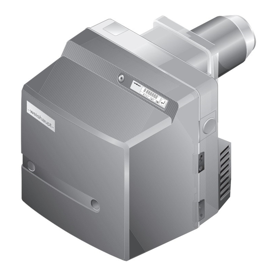
Gas Burner WG20…/1-C ZM-LN (W-FM 25)
83055116 • 1/2016-05
Related Manuals for Weishaupt WG20 Series
Summary of Contents for Weishaupt WG20 Series
-
Page 1
manual Installation and Operating Instructions Certified for use in USA / Canada Conforms to / à UL std 795 (R2013), UL std 295 (R2015) and UL std 296 (R2013) Certified / certifié CSA std 3.4 (R2009) Gas Burner WG20…/1-C ZM-LN (W-FM 25) 83055116 •… -
Page 2
83055116 • 1/2016-05 Front cover: WG20…/1-C ZM-LN… -
Page 3
Installation and Operating Instructions Gas burner WG20…/1-C ZM-LN (W-FM 25) User instructions……………………… 5 Information for user………………….5 1.1.1 Symbols……………………..5 1.1.2 Target group……………………..5 General instructions………………….6 Safety information……………………7 Technical description……………………9 Permissible applications…………………9 Nomenclature……………………9 Basic functions……………………9 3.3.1 Air supply……………………..10 3.3.2 Gas supply…………………….. 10 3.3.3 Electrical components………………….11 3.3.4 Program sequence………………….12 3.3.5 Inputs and outputs…………………. -
Page 4
Installation and Operating Instructions Gas burner WG20…/1-C ZM-LN (W-FM 25) Commissioning and startup………………..31 Conditions………………………31 6.1.1 Connecting measuring device………………32 6.1.2 Air pressure switch presetting………………33 6.1.3 Gas pressure regulator presetting……………..33 6.1.4 Setting values……………………34 Burner setting……………………35 Setting air pressure switch………………..42 Concluding works………………….42 Combustion analysis………………….43 Calculating gas throughput………………… -
Page 5
Installation and Operating Instructions Gas burner WG20…/1-C ZM-LN (W-FM 25) 1 User instructions 1.1 Information for user This installation and operating instruction is part of the equipment and must be kept at the installation at all time. As supplement to this document is the Installation and Operating Instructions for Combustion Manager W-FM 25. -
Page 6
Standard Weishaupt burners are designed for indoor use only. For outdoor installa- tions, contact your Weishaupt representative. The installation of any Weishaupt product must be carried out by fully qualified and licensed personnel. The personnel performing the work must be familiar with, and operate within the appli- cable local and national codes, such as CAN/CSA B149.1, 2, 3, CAN/CSA B139-00,… -
Page 7
2 Safety information Dangers when using the equipment Weishaupt products are manufactured in accordance with the relevant existing standards and guidelines, and the recognized safety laws. However, improper use of the equipment could endanger the life of the user or third party or result in damage to the plant. -
Page 8
• No additional components, which have not been tested for use with the equipment, may be installed. • Use only genuine -weishaupt- replacement and connection parts. • Parts from other manufacturers are not guaranteed to be suitable to meet the necessary operational and safety requirements. -
Page 9
Gas burner WG20…/1-C ZM-LN (W-FM 25) 3 Technical description 3.1 Permissible applications Weishaupt gas burner WG20…/1-C ZM-LN is suitable for the following applications: • Installation on heat exchanger. • Warm water boiler . • Steam boiler and hot water boiler. -
Page 10
3.3.2 Gas supply Gas train Weishaupt gas and dual fuel burners are equipped as standard with dual safety gas valves, in single or double valve body configuration. * This gas train configuration is for reference only. Actual gas train configuration may… -
Page 11
Installation and Operating Instructions Gas burner WG20…/1-C ZM-LN (W-FM 25) 3 Technical description 3.3.2. Gas supply (cont.) 6 Low gas pressure switch The low gas pressure switch monitors the gas supply pressure. With too low gas pressure, the burner start will be prevented. 7 Additional low gas pressure switch The additional low gas pressure switch monitors the gas pressure downstream of the pressure regulator SKP25. -
Page 12
Installation and Operating Instructions Gas burner WG20…/1-C ZM-LN (W-FM 25) 3 Technical description 3.3.4 Program sequence The burner operating phases are shown on the display, as following: Phase Function TEST After the power supply is switched on, the combustion manager performs a self-test. At call for heat, the air and gas stepping motors drive to the reference position. -
Page 13
Installation and Operating Instructions Gas burner WG20…/1-C ZM-LN (W-FM 25) 3 Technical description W-FM 25 T1 T2 1234 1234 Ionization electrode CLOSED position Air pressure switch Ignition position Temperature/pressure operating ctrl. (On/Off) Low fire Temperature/pressure 2-stage or modulating ctrl. High fire Low gas pressure switch Operating phase High gas pressure switch… -
Page 14
Air damper stepping motor Gas butterfly valve stepping motor Slot for analogue module EM3/3 or Fieldbus module EM3/2 External valve LPG (optional) -weishaupt- Burner motor for continuous running blower Burner motor for normal blower operation Ignition unit Double gas valves Not used Bridging plug No. -
Page 15
Installation and Operating Instructions Gas burner WG20…/1-C ZM-LN (W-FM 25) 3 Technical description 3.4 Technical data 3.4.1 Electrical data Burner control Mains voltage / frequency 110 V / 60Hz Power consumption — start max 436 W Power consumption — operation max 336 W Operating current max 3 A… -
Page 16
Installation and Operating Instructions Gas burner WG20…/1-C ZM-LN (W-FM 25) 3 Technical description 3.4.4 Capacity Firing rate Natural gas 119 … 682 MBTU/H Propane 119 … 682 MBTU/H Combustion head WG20-C Capacity graph The capacity graph is based on fuel with low calorific value and tested at sea level. Capacity reduction should be applied depending on the altitude of the installation: approx. -
Page 17
Installation and Operating Instructions Gas burner WG20…/1-C ZM-LN (W-FM 25) 3 Technical description 3.4.5 Dimensions Rp1” –weishaupt– 1-1/4” 14-1/8” (358 mm) (32 mm) 6-1/4” (158 mm) 15-5/8” (397 mm) 5-1/2” (140 mm) — without combustion head extension 9-1/2” (240 mm) — with 3-7/8” (100 mm) combustion head extension 13-3/8”… -
Page 18
Installation and Operating Instructions Gas burner WG20…/1-C ZM-LN (W-FM 25) 4 Installation 4.1 Preparation prior to installation Check burner’s rating plate and capacity graph Check the burner type and rating. The burner rating must be within the operating range of the heating appliance. The ratings given on the burner plate are the minimum and maximum possible firing rates of the burner. -
Page 19
Installation and Operating Instructions Gas burner WG20…/1-C ZM-LN (W-FM 25) 4 Installation 4.2 Burner installation SWITCH OFF POWER FIRST! Prior to the installation, switch off the mains switch and the safety switch. Failure to comply could cause death or serious injury by electric shock. DANGER The burner in its standard version is designed for gas train connection from the right. -
Page 20
Installation and Operating Instructions Gas burner WG20…/1-C ZM-LN (W-FM 25) 4 Installation 4.2.1 Rotate burner by 180° Install the operating interface 1 on the opposite side of the burner’s housing. Install the fixing bracket of the burner housing 3 on the opposite side of the burner’s housing. -
Page 21
Installation and Operating Instructions Gas burner WG20…/1-C ZM-LN (W-FM 25) 4 Installation 4.3 Gas supply Risk of explosion! Gas leaks can lead to the build up of explosive gas — air mixtures. With the presence of an ignition source, these could lead to an explosion. DANGER To avoid accidents, please comply to the following safety information on the gas train installation:… -
Page 22
Installation and Operating Instructions Gas burner WG20…/1-C ZM-LN (W-FM 25) 4 Installation 4.4 Electrical connection SWITCH OFF POWER FIRST! Before the installation, switch off the main switch and the safety switch. Failure to comply could cause death, or serious injury by electric shock. DANGER Burner specific wiring diagram The electrical connection must be made according to the wiring diagram enclosed with… -
Page 23
Installation and Operating Instructions Gas burner WG20…/1-C ZM-LN (W-FM 25) 5 Operation 5.1 Operating interface Function [G] Gas key Select gas butterfly valve stepping motor [-] Minus key Decrease value [+] Plus key Increase value [L/A] Air key Select air damper stepping motor [Enter] Enter key Reset burner;… -
Page 24
Installation and Operating Instructions Gas burner WG20…/1-C ZM-LN (W-FM 25) 5 Operation Operating level The current stepping motor position and/or blower speed can be displayed in the operating level (10 ). Displaying the gas butterfly valve setting: Press [G] key. Displaying the air damper setting: Press [L/A] key. -
Page 25
Installation and Operating Instructions Gas burner WG20…/1-C ZM-LN (W-FM 25) 5 Operation 5.2 Display The display shows the current operating statuses and operating data. 1 Programming level activated 2 Start phase activated 3 Info level activated 4 Stepping motor runs to CLOSED position 5 Stepping motor runs to OPEN position 6 Burner in operation 7 Lockout… -
Page 26
Installation and Operating Instructions Gas burner WG20…/1-C ZM-LN (W-FM 25) 5 Operation 5.2.1 Info mode Burner status and information can be retrieved in the Info mode. Press [Enter] for approx. 0.5 sec. The Info level is activated. Press [Enter] to reach the next information. l,m³… -
Page 27
Installation and Operating Instructions Gas burner WG20…/1-C ZM-LN (W-FM 25) 5 Operation 5.2.2 Service mode The Service mode gives information about: • Stepping motor position of the individual operating points; • The most recent fault; • Flame signal during burner operation. Press [Enter] for approx. -
Page 28
Installation and Operating Instructions Gas burner WG20…/1-C ZM-LN (W-FM 25) 5 Operation 5.2.3 Parameter mode The Parameter mode can only be called up in Stand-by (OFF) mode. Press [+] and [Enter] simultaneously for approx. 2 sec. The Parameter mode is activated. Press [+]. -
Page 29
Installation and Operating Instructions Gas burner WG20…/1-C ZM-LN (W-FM 25) 5 Operation 5.2.4 Access mode In the Access mode, the configuration can be adapted relative to the burner type or version. In the Parameter mode, the display mode must be configured to ON, in order to enable access to parameters E0 . -
Page 30
Installation and Operating Instructions Gas burner WG20…/1-C ZM-LN (W-FM 25) 5 Operation 5.3 Linearization During commissioning, it is possible to carry out the linearization of the operating points in gas operation. During linearization, a straight line is generated from the operating point displayed, to P9. -
Page 31
Installation and Operating Instructions Gas burner WG20…/1-C ZM-LN (W-FM 25) 6 Commissioning and startup 6.1 Conditions Commissioning and startup must only be carried out by trained and qualified person- nel. Prior to commissioning, all installation works must be completed and checked. The burner must be installed on the heat exchanger and ready to function with all control and safety devices connected. -
Page 32
Installation and Operating Instructions Gas burner WG20…/1-C ZM-LN (W-FM 25) 6 Commissioning and startup 6.1.1 Connecting measuring devices Measuring device for the ionization current Remove ionization cable from the plug coupling. Connect the current measuring device in series. Ionization current 1 μA Extraneous light detection from: 5 μA… -
Page 33
Installation and Operating Instructions Gas burner WG20…/1-C ZM-LN (W-FM 25) 6 Commissioning and startup 6.1.2 Air pressure switch presetting The air pressure switch presetting is only valid during commissioning. After completing the commissioning, the air pressure switch must be set correctly. Air pressure switch pre-setting prior to commissioning: — approx. -
Page 34
Installation and Operating Instructions Gas burner WG20…/1-C ZM-LN (W-FM 25) 6 Commissioning and startup 6.1.4 Setting values Set the mixing head relative to the required burner capacity. For this, the diffuser setting and the air damper setting should be matched. Determine the diffuser and the air damper settings Do not operate the burner outside its capacity graph. -
Page 35
Installation and Operating Instructions Gas burner WG20…/1-C ZM-LN (W-FM 25) 6 Commissioning and startup 6.2 Burner setting Risk of electric shock Touching the ignition device can lead to electric shock. DANGER Do not touch the ignition device during the ignition process! Check the flame signal during commissioning (see Ch. -
Page 36
Installation and Operating Instructions Gas burner WG20…/1-C ZM-LN (W-FM 25) 6 Commissioning and startup 6.2. Burner setting (cont.) Press [+] key to confirm the factory setting. The combustion manager is preset. 2. Checking the sequence of operation Open the gas isolating valve, reset the low gas pressure switch if necessary. The pressure in the gas train increases. -
Page 37
Installation and Operating Instructions Gas burner WG20…/1-C ZM-LN (W-FM 25) 6 Commissioning and startup 3. Presetting the gas setting pressure If a controlled shutdown or lockout occurs during setting: Briefly press [G] and [L/A] keys simultaneously. Press [+] key. The combustion manager changes to setting level. Open the test point for the setting pressure and connect the pressure measuring device. -
Page 38
Installation and Operating Instructions Gas burner WG20…/1-C ZM-LN (W-FM 25) 6 Commissioning and startup 4. Driving to high fire Press [+] key. The burner drives to the operating point P1. Check the CO content in the flue gas and, if necessary, adjust combustion values via the gas butterfly setting [G]. -
Page 39
Installation and Operating Instructions Gas burner WG20…/1-C ZM-LN (W-FM 25) 83055116 • 1/2016-05… -
Page 40
Installation and Operating Instructions Gas burner WG20…/1-C ZM-LN (W-FM 25) 6 Commissioning and startup 8. Performing the linearization process Press [+] key. The burner drives to the operating point P1. Press [Enter] key. The combustion manager switches to linearization mode. Confirm with [+] key. -
Page 41
Installation and Operating Instructions Gas burner WG20…/1-C ZM-LN (W-FM 25) 83055116 • 1/2016-05… -
Page 42
Installation and Operating Instructions Gas burner WG20…/1-C ZM-LN (W-FM 25) 6 Commissioning and startup 6.3 Setting the air pressure switch Switching point must be checked and, if necessary, adjusted during commissioning. Connect the pressure gauge for differential pressure measurement. Start the burner. Check differential pressure over the whole operating range and determine the lowest differential pressure. -
Page 43
Installation and Operating Instructions Gas burner WG20…/1-C ZM-LN (W-FM 25) 6 Commissioning and startup 6.5 Combustion analysis For safe and economic operation of the plant, flue gas measurements are essential when commissioning. The maximum CO content for various gases can be obtained from the gas suppliers. Example: With 15% excess air ( = 1.15) and 12% CO max. -
Page 44
Installation and Operating Instructions Gas burner WG20…/1-C ZM-LN (W-FM 25) 6 Commissioning and startup 6.6 Calculating the gas throughput To provide the correct thermal input to the appliance, the required gas throughput must be determined beforehand. Conversion from standard to operating conditions The calorific value (H) of combustible gases is generally given in relation to the standard barometric conditions. -
Page 45
Installation and Operating Instructions Gas burner WG20…/1-C ZM-LN (W-FM 25) 6 Commissioning and startup 6.7 Subsequent optimization of the operating points For safe and economic operation of the plant, the combustion values can subsequently be corrected. Unplug the bridging plug No. 7 from the combustion manager. The combustion manager drives to stand-by. -
Page 46
Installation and Operating Instructions Installation and Operating Instructions Gas burner WG20…/1-C ZM-LN (W-FM 25) Gas burner WG20…/1-C ZM-LN (W-FM 25) 7 Shutdown 7. Shutdown For breaks in operation: Switch off the power supply to the burner. Close the gas shut off devices. 83055116 •… -
Page 47
Installation and Operating Instructions Gas burner WG20…/1-C ZM-LN (W-FM 25) 8 Maintenance and service 8.1 Notes on maintenance and service Risk of explosion due to leaking gas When dismantling and assembling components which are used in the gas line, ensure that they are correctly cross bonded, aligned, clean and in good condition, and that the fixing screws are correctly tightened. -
Page 48
Installation and Operating Instructions Installation and Operating Instructions Gas burner WG20…/1-C ZM-LN (W-FM 25) Gas burner WG20…/1-C ZM-LN (W-FM 25) 8 Maintenance and service 8.2 Service plan Components Criteria / design lifespan Maintenance or service procedure Blower wheel Soiling Clean Damage Replace Air duct… -
Page 49
Installation and Operating Instructions Gas burner WG20…/1-C ZM-LN (W-FM 25) 8 Maintenance and service 8.3 Removing and re-installing the mixing head Observe the notes on maintenance and servicing (see Ch. 8.1). Risk of explosion due to leaking gas Gas leakage could occur if the gasket 3 is seated incorrectly. Following work at the mixing head, ensure that the gasket is clean and seated correctly. -
Page 50
Installation and Operating Instructions Installation and Operating Instructions Gas burner WG20…/1-C ZM-LN (W-FM 25) Gas burner WG20…/1-C ZM-LN (W-FM 25) 8 Maintenance and service 8 Maintenance and service 8.4 Setting the mixing head Observe the notes on maintenance and servicing (see Ch. 8.1). The distance S1 between the diffuser and the flame tube’s front edge cannot be mea- sured with the burner mounted. -
Page 51
Installation and Operating Instructions Gas burner WG20…/1-C ZM-LN (W-FM 25) 8 Maintenance and service 8.5 Setting the ionization and the ignition electrodes Observe the notes on maintenance and servicing (see Ch. 8.1). Remove the mixing head (see Ch. 8.3). Loosen screw 1. Set the ignition electrode and re-tighten screw 1. -
Page 52
Installation and Operating Instructions Installation and Operating Instructions Gas burner WG20…/1-C ZM-LN (W-FM 25) Gas burner WG20…/1-C ZM-LN (W-FM 25) 8 Maintenance and service 8.6 Service position Observe the notes on maintenance and servicing (see Ch. 8.1). The burner mounted rotated by 180º cannot be placed into service position. Remove the mixing head (see Ch. -
Page 53
Installation and Operating Instructions Gas burner WG20…/1-C ZM-LN (W-FM 25) 8 Maintenance and service 8.7 Removing and re-installing the blower wheel Observe the notes on maintenance and servicing (see Ch. 8.1). Removing Place the housing cover into service position (see Ch. 8.6). Remove the set screw 1 and remove the blower wheel. -
Page 54
Installation and Operating Instructions Installation and Operating Instructions Gas burner WG20…/1-C ZM-LN (W-FM 25) Gas burner WG20…/1-C ZM-LN (W-FM 25) 8 Maintenance and service 8.8 Removing the burner motor Observe the notes on maintenance and servicing (see Ch. 8.1). Remove the blower wheel (see Ch. 8.7). Unplug the plugs number 3 and 11. -
Page 55
Installation and Operating Instructions Gas burner WG20…/1-C ZM-LN (W-FM 25) 8 Maintenance and service 8.9 Removing and re-installing the air damper stepping motor Observe the notes on maintenance and servicing (see Ch. 8.1). Removing Remove the stepping motor plug 4 from the combustion manager. Remove the screws 3. -
Page 56
Installation and Operating Instructions Installation and Operating Instructions Gas burner WG20…/1-C ZM-LN (W-FM 25) Gas burner WG20…/1-C ZM-LN (W-FM 25) 8 Maintenance and service 8.10 Removing and re-installing the angle drive Observe the notes on maintenance and servicing (see Ch. 8.1). Removing Remove the air damper stepping motor (see Ch. -
Page 57
Installation and Operating Instructions Gas burner WG20…/1-C ZM-LN (W-FM 25) 8 Maintenance and service 8.11 Removing and re-installing the gas butterfly valve stepping motor Observe the notes on maintenance and servicing (see Ch. 8.1). Removing Remove the stepping motor plug 1 from the combustion manager. Remove the screws 2. -
Page 58
Installation and Operating Instructions Installation and Operating Instructions Gas burner WG20…/1-C ZM-LN (W-FM 25) Gas burner WG20…/1-C ZM-LN (W-FM 25) 8 Maintenance and service 8.12 Removing and re-installing the gas butterfly valve Observe the notes on maintenance and servicing (see Ch. 8.1). Removing Unscrew the double nipple R1”-1”NPT 3 from the gas butterfly valve. -
Page 59
Installation and Operating Instructions Gas burner WG20…/1-C ZM-LN (W-FM 25) 8 Maintenance and service 8.13 Removing and re-installing the air regulator Observe the notes on maintenance and servicing (see Ch. 8.1). Removing Remove the burner from the appliance. Remove the stepping motor plug 5. Remove the screws 2. -
Page 60
Installation and Operating Instructions Installation and Operating Instructions Gas burner WG20…/1-C ZM-LN (W-FM 25) Gas burner WG20…/1-C ZM-LN (W-FM 25) 8 Maintenance and service 8.14 Replacing the combustion manager Observe the notes on maintenance and servicing (see Ch. 8.1). Unplug all the plugs. Loosen screws 1. -
Page 61
Installation and Operating Instructions Gas burner WG20…/1-C ZM-LN (W-FM 25) 8 Maintenance and service Press [+]. The setting level (parameter E0 ) is displayed. Select value 0 (single fuel burner), if necessary, adjust using [Enter] and [-] keys. Press [+]. E1 is displayed. -
Page 62
Installation and Operating Instructions Gas burner WG20…/1-C ZM-LN (W-FM 25) 8 Maintenance and service 8.15 Replacing the combustion manager’s fuse Observe the notes on maintenance and servicing (see Ch. 8.1). Unplug the connection plug X6 from the combustion manager. Replace the blown fuse with the replacement fuse 1 (6.3 AT). Reconnect the plug X6. -
Page 63
Top up the water in the boiler. has tripped. Reset the Low Water safety interlock on the boiler. Notify Weishaupt Customer Service or your Weishaupt representative if this problem occurs repeatedly. 9.1.2 Display showing OFF The following faults may be corrected by the operator: Fault… -
Page 64
Installation and Operating Instructions Gas burner WG20…/1-C ZM-LN (W-FM 25) 9 Faults rectification 9.1.3 Display flashes A burner fault has occurred. The burner is in lockout. The error code is displayed flashing. Read the error code, e.g. A7h. Rectify the cause of the fault (see Ch. 9.2). Resetting Damage could result from incorrect servicing The burner could be damaged. -
Page 65
Installation and Operating Instructions Gas burner WG20…/1-C ZM-LN (W-FM 25) 9 Faults rectification 9.1.4 Detailed fault codes Additional information, which breaks down the error in more detail, can be displayed by pressing a button. The first detailed fault code and the second detailed fault code are relevant only for the following faults: •… -
Page 66
Installation and Operating Instructions Gas burner WG20…/1-C ZM-LN (W-FM 25) 9 Faults rectification 9.2 Fault codes, causes and rectification The following faults must be rectified only by qualified personnel: Fault codes Cause Rectification 02h Internal unit fault Switch off the power supply temporarily. Reset the burner. -
Page 67
Installation and Operating Instructions Gas burner WG20…/1-C ZM-LN (W-FM 25) 9 Faults rectification The following faults must be rectified only by qualified personnel: Fault codes Cause Rectification Switch off via PC software Second detailed fault code: Check Fieldbus address. Invalid Fieldbus address Second detailed fault code: Check configuration at output B4. -
Page 68
Installation and Operating Instructions Gas burner WG20…/1-C ZM-LN (W-FM 25) 9 Faults rectification The following faults must be rectified only by qualified personnel: Fault codes Cause Rectification Operating points were changed Re-adjust the burner. without approval Parameter E3 set incorrectly Check parameter E3 (access level). -
Page 69
Installation and Operating Instructions Gas burner WG20…/1-C ZM-LN (W-FM 25) 9 Faults rectification The following faults must be rectified only by qualified personnel: Fault codes Cause Rectification First detailed fault code: Check freedom of movement of air damper and/or angle drive and gas butterfly valve. Tolerance fault air stepping motor, gas Replace the stepping motor. -
Page 70
Installation and Operating Instructions Gas burner WG20…/1-C ZM-LN (W-FM 25) 9 Faults rectification The following faults must be rectified only by qualified personnel: Fault codes Cause Rectification Flame failure during operation Check burner setting. Check the ionization electrode, replace if necessary. See A7h. -
Page 71
Installation and Operating Instructions Gas burner WG20…/1-C ZM-LN (W-FM 25) 9 Faults rectification 9.3 Operating problems The following faults must be rectified only by qualified personnel: Observation Cause Rectification Poor start behaviour of the burner Mixing pressure too high Decrease mixing pressure at ignition position. -
Page 72
Oil, gas and dual fuel burners for industrial plant. Control technology / From control panels to complete building management Building systems – at Weishaupt you can find the entire Management spectrum of modern control technology. System (BMS) Future oriented, economical and flexible.
Типоряд W 5—40
— W5
— W10
— W20
— W30
— W40
Типоряд WM monarch
— WM 10
— WM 20
— WM 30
— WM 50
Типоряд 30—70
— 30-70
Типоряд WK
— WK 40-80
Типоряд WKmono
— WKmono 80
Типоряд W 5—40
W5
Газовые горелки
 Постоянная работа двигателя, горелки WG(L). Инструкция по монтажу, 5515RUS, 1/2019-04 Постоянная работа двигателя, горелки WG(L). Инструкция по монтажу, 5515RUS, 1/2019-04 |
|
| Система забора воздуха для горелок Weishaupt. Инструкция по монтажу, 5479RUS, 1/2017-06 |
|
| Внимание! Дополнительный лист. План проведения техобслуживания газовых горелок WG 5 … 40, 5393 RUS-1/2017 |
|
| WG 5. Горелки газовые, исполнение LN, 0512RUS, 1/2020-01 |
|
| WG 5. Горелки газовые, руководство по обслуживанию, 1296RUS-1/02 |
Жидкотопливные горелки
| WL5/1-B H-2LN. Жидкотопливные горелки, 0584RUS — 1/2016-08 |
|
| WL5/1-B исп. H. Горелки жидкотопливные, руководство по монтажу и эксплуатации, 2721RUS-1/2019-03 |
|
| Постоянная работа двигателя, горелки WL. Инструкция по монтажу, 5516 RUS 1/2017-11 |
|
| Система забора воздуха для горелок Weishaupt. Инструкция по монтажу, 5479RUS, 1/2017-06 |
|
| WL5/2-B, Жидкотопливные горелки, 2722RUS, — 1/2019-04 |
|
| WL5/1-B, Жидкотопливные горелки, 2720RUS, 1/2016-08 |
|
| Внимание! Дополнительный лист. План проведения техобслуживания ж/т горелок WL 5 … 40, 5394 RUS-1/2017 |
|
| WL5/1-B-H. Горелки дизельные, исполнение 2LN. Без насадки на пламенную голову для реверсивных котлов, 1644RUS-1/04 |
|
| WL5-A-Н. Горелки дизельные, исполнение 1LN, 522RUS-1/01 |
|
| WL 5. Горелки дизельные, исполнение стандартное и с подогревом топлива, 511RUS-1/01 |
|
| WL 5. Горелки дизельные, исполнение стандартное и с подогревом, 583RUS-1/03 |
|
| WL 5. Горелки дизельные, исполнение H-2LN, 584RUS-1/03 |
W10
Газовые горелки
| Постоянная работа двигателя, горелки WG(L). Инструкция по монтажу, 5515 RUS 1/2017-11 |
|
| Система забора воздуха для горелок Weishaupt. Инструкция по монтажу, 5479RUS, 1/2017-06 |
|
| Арматура с W-MF для давления на входе > 150 мбар, 5109 1/2016-04 |
|
| Внимание! Дополнительный лист. План проведения техобслуживания газовых горелок WG 5 … 40, 5393 RUS-1/2017 |
|
| WG10…/0-D. Горелки газовые, исполнение ZM-LN, 3009 RUS-1/16 |
|
| WG 10…/1-D. Горелки газовые, исполнение ZM-LN, 554RUS-1/16 |
|
| WG10…/1-D. Горелки газовые, исполнение LN, 0587RUS, 1/2020-01 |
|
| WG10…/1-D. Горелки газовые, исполнение Z-LN, 0553RUS, 1/2020-01 |
Жидкотопливные горелки
| WL10/1-D 1LN . Жидкотопливные горелки, 2993RUS,1/2019-04 |
|
| WL10/2-D 1LN . Жидкотопливные горелки, 2994RUS, 1/2019-04 |
|
| WL10/2-D . Жидкотопливные горелки, 2925RUS, 1/2019-04 |
|
| Постоянная работа двигателя, горелки WL. Инструкция по монтажу, 5516 RUS 1/2017-11 |
|
| WL10/2-D исп. Z. Жидкотопливные горелки, 2927RUS, 1/2019-04 |
|
| WL10/3-D исп. Z. Жидкотопливные горелки, 2928RUS, 1/2019-04 |
|
| WL10/3-D. Жидкотопливные горелки, 2926RUS, 1/2019-04 |
|
| Система забора воздуха для горелок Weishaupt. Инструкция по монтажу, 5479RUS, 1/2017-06 |
|
| Внимание! Дополнительный лист. План проведения техобслуживания ж/т горелок WL 5 … 40, 5394 RUS-1/2017 |
W20
Газовые горелки
| WG 20…/1-C. Горелки газовые, исполнение Z-LN, 0546RUS 1/2020-01 |
|
| Постоянная работа двигателя, горелки WG(L). Инструкция по монтажу, 5515 RUS 1/2017-11 |
|
| Система забора воздуха для горелок Weishaupt. Инструкция по монтажу, 5479RUS, 1/2017-06 |
|
| Арматура с W-MF для давления на входе > 150 мбар, 5109 1/2016-04 |
|
| Внимание! Дополнительный лист. План проведения техобслуживания газовых горелок WG 5 … 40, 5393 RUS-1/2017 |
|
| WG 20…/1-С. Горелки газовые, исполнение ZM-LN, 551RUS-1/16 |
|
| WG 20…/1-C. Горелки газовые, исполнение LN, 2408RUS-1/04 |
Жидкотопливные горелки
| WL 20/2-C исполнение Z. Жидкотопливные горелки, 3077RUS, 1/2019-04 |
|
| WL20/1-C Z. Жидкотопливные горелки, 3076RUS — 1/2019-04 |
|
| Постоянная работа двигателя, горелки WL. Инструкция по монтажу, 5516 RUS 1/2017-11 |
|
| WL20/1-C Z исполнение 1LN, Жидкотопливные горелки, 559RUS-1/2017-05 |
|
| Система забора воздуха для горелок Weishaupt. Инструкция по монтажу, 5479RUS, 1/2017-06 |
|
| WL 20/2-С. Горелки дизельные, одноступенчатые, 3021RUS — 1/2016-08 |
|
| Внимание! Дополнительный лист. План проведения техобслуживания ж/т горелок WL 5 … 40, 5394 RUS-1/2017 |
|
| WL 20. Горелки дизельные, исполнение Z, двухступенчатые, 549RUS-1/01 |
|
| WL 20/1-С. Горелки дизельные, одноступенчатые, 3020RUS — 1/2019-04 |
W30
Газовые и комбинированные горелки
| WG30…/1-C ZM-LN. Горелки газовые, руководство по монтажу и эксплуатации, 2999RUS-1/2019-02 |
|
| Постоянная работа двигателя, горелки WG(L). Инструкция по монтажу, 5515 RUS 1/2017-11 |
|
| Система забора воздуха для горелок Weishaupt. Инструкция по монтажу, 5479RUS, 1/2017-06 |
|
| Арматура с W-MF для давления на входе > 150 мбар, 5109 1/2016-04 |
|
| Внимание! Дополнительный лист. План проведения техобслуживания газовых горелок WG 5 … 40, 5393 RUS-1/2017 |
|
| Внимание! Дополнительный лист. План проведения техобслуживания комбинированных горелок WGL 30 … 40, 5395 RUS-1/2017 |
|
| WGL30/1-C исп. ZM. Горелки комбинированные, руководство по монтажу и эксплуатации, 2602RUS-1/2019-02 |
|
| WG30/1 С, WG 40/1 А. Горелки газовые, исполнение ZM LN 489RUS 1/04 |
|
| WGL30. Горелки комбинированные с менеджером горения W-FM24, 2602RUS-1/2011 |
|
| WG 30 и WG 40. Горелки газовые, исполнение ZM-LN, с частотным регулированием двигателя, 552RUS-1/02 |
Жидкотопливные горелки
| WL 30 Z-C исполнения 4LN. Жидкотопливные горелки, руководство по монтажу и эксплуатации, 2988RUS, 2/2019-05 |
|
| Постоянная работа двигателя, горелки WL. Инструкция по монтажу, 5516 RUS 1/2017-11 |
|
| Система забора воздуха для горелок Weishaupt. Инструкция по монтажу, 5479RUS, 1/2017-06 |
|
| Внимание! Дополнительный лист. План проведения техобслуживания ж/т горелок WL 5 … 40, 5394 RUS-1/2017 |
|
| WL 30 Z-C с WFM 25. Жидкотопливные горелки, руководство по монтажу и эксплуатации, 2979RUS 3/2019-11 |
|
| WL 30Z-C. Горелки дизельные, на технологической установке, 1976RUS-1/2010 |
W40
Газовые и комбинированные горелки
| Постоянная работа двигателя, горелки WG(L). Инструкция по монтажу, 5515 RUS 1/2017-11 |
|
| Система забора воздуха для горелок Weishaupt. Инструкция по монтажу, 5479RUS, 1/2017-06 |
|
| Арматура с W-MF для давления на входе > 150 мбар, 5109 1/2016-04 |
|
| Внимание! Дополнительный лист. План проведения техобслуживания газовых горелок WG 5 … 40, 5393 RUS-1/2017 |
|
| Внимание! Дополнительный лист. План проведения техобслуживания комбинированных горелок WGL 30 … 40, 5395 RUS-1/2017 |
|
| WG40…/1-A исп. ZM-LN с WFM 25, Газовые горелки, руководство по монтажу и эксплуатации, 3000 1/2019 |
|
| WGL40/1-A ZM. Горелки комбинированные, руководство по монтажу и эксплуатации, 2734RUS-1/2019-02 |
|
| WG 30 и WG 40. Горелки газовые, исполнение ZM-LN, с частотным регулированием двигателя, 552RUS-1/02 |
|
| WG30/1-С, WG40/1-А. Горелки газовые, исполнение ZM-LN, 489RUS-1/04 |
Жидкотопливные горелки
| WL40Z-A 1LN . Жидкотопливные горелки, 2989RUS, 2/2019-05 |
|
| Постоянная работа двигателя, горелки WL. Инструкция по монтажу, 5516 RUS 1/2017-11 |
|
| Система забора воздуха для горелок Weishaupt. Инструкция по монтажу, 5479RUS, 1/2017-06 |
|
| WL 40 Z-А. Жидкотопливные горелки, 2980RUS, 3/2019-11 |
|
| Внимание! Дополнительный лист. План проведения техобслуживания ж/т горелок WL 5 … 40, 5394 RUS-1/2017 |
|
| WL 40Z-C. Горелки дизельные, на технологической установке, 1977RUS-1/2010 |
Типоряд WM monarch
WM 10
| WM-G10/1-A исп. ZM с W-FM 50. Горелки газовые, руководство по монтажу и эксплуатации, 2618RUS-1/2018 |
|
| WM-G10/1-A исп. ZM-LN с W-FM 50. Горелки газовые, руководство по монтажу и эксплуатации, 2637RUS-1/2011 |
|
| WM-G10/1-A исп. ZM c W-FM 100/200. Горелки газовые, руководство по монтажу и эксплуатации, 2427RUS-1/2018 |
|
| WM-G10/1-A исп. ZM-LN с W-FM 100/200. Горелки газовые, руководство по монтажу и эксплуатации, 2431RUS-1/2011 |
|
| WM-G10/1-A исп. ZMI с W-FM 100/200. Горелки газовые, руководство по монтажу и эксплуатации, 2651RUS-1/2011 |
|
| WM-G10/2-A исп. ZM с W-FM 50. Горелки газовые, руководство по монтажу и эксплуатации, 2495RUS-1/2019 |
|
| WM-G10/2-A исп. ZM-LN с W-FM 50. Горелки газовые, руководство по монтажу и эксплуатации, 2500RUS-1/2011 |
|
| WM-G10/2-A исп. ZM с W-FM100. Горелки газовые, руководство по монтажу и эксплуатации, 2428RUS-1/2019 |
|
| WM-G10/2-A исп. ZM-LN с W-FM 100. Горелки газовые, руководство по монтажу и эксплуатации, 2432RUS-2/2020-05 |
|
| WM-G10/2-A исп. ZMI с W-FM 100. Горелки газовые, руководство по монтажу и эксплуатации, 2652-1/2011 |
|
| WM-G10/3-A исп. ZM с W-FM 50. Горелки газовые, руководство по монтажу и эксплуатации, 2496RUS-1/2019 |
|
| WM — G10/3-A / ZM-LN с W-FM 50. Горелки газовые, руководство по монтажу и эксплуатации, 2501RUS — 1/2019-07 |
|
| WM — G10/3-A исп. ZM с W-FM 100/200. Газовые горелки, руководство по монтажу и эксплуатации, 2429RUS — 1/2019-01 |
|
| WM — G10/3-A / ZM-LN с W-FM 100/200. Горелки газовые, руководство по монтажу и эксплуатации, 2433RUS — 1/2019-07 |
|
| WM-G10/3-A исп. ZMI c W-FM 100/200. Горелки газовые, руководство по монтажу и эксплуатации, 2653RUS- 1/2011 |
|
| WM-G10/4-A исп. ZM с W-FM 50. Горелки газовые, руководство по монтажу и эксплуатации, 2497RUS-1/2019 |
|
| WM-G10/4-A исп. ZM с W-FM 100. Горелки газовые, руководство по монтажу и эксплуатации, 2430RUS-1/2011 |
|
| WM-G10/4-A исп. ZMI с W-FM 100/200. Горелки газовые, руководство по монтажу и эксплуатации, 2654RUS-1/2011 |
|
| WM-GL10/1-A исп. ZM-T с W-FM 100. Горелки комбинированные, руководство по монтажу и эксплуатации, 2461RUS-1/2007 |
|
| WM-GL10/2-A исп. ZM-T с W-FM 100. Горелки комбинированные, руководство по монтажу и эксплуатации, 2462RUS-1/2009 |
|
| WM-GL10/2-A исп. ZM-R с W-FM 54. Горелки комбинированные, руководство по монтажу и эксплуатации, 2657RUS-1/2012 |
|
| WM-GL10/2-A исп. ZM-R с W-FM 100. Горелки комбинированные, руководство по монтажу и эксплуатации, 2464RUS-1/2020-06 |
|
| WM-GL10/3-A исп. ZM-T с W-FM 100. Горелки комбинированные, руководство по монтажу и эксплуатации, 2463RUS-1/2006 |
|
| WM — GL10/3-A исп. ZM-R с W-FM 100/200. Комбинированная горелка, руководство по монтажу и эксплуатации, 2465RUS — 1/2019-02 |
|
| WM-GL10/1-A исп. ZM-T с W-FM 54. Горелки комбинированные , руководство по монтажу и эксплуатации, 2614RUS-1/2009 |
|
| WM-GL10/2-A исп. ZM-T с W-FM 54. Горелки комбинированные, руководство по монтажу и эксплуатации, 2615RUS-1/2012 |
|
| WM-GL10/3-A исп. ZM-T с W-FM 54. Горелки комбинированные , руководство по монтажу и эксплуатации, 2616RUS-1/2017 |
|
| WM — GL 10/4-A / ZM-T с W-FM 54. Горелки комбинированные, руководство по монтажу и эксплуатации, 2617RUS-1/2019-02 |
|
| WM — G10/3-A исп. ZM-3LN multiflam® с W-FM 50. Горелки газовые, руководство по монтажу и эксплуатации, 2589RUS-1/2018-11 |
|
| WM-L10/4-A исп.T с W-FM 50. Горелки жидкотопливные, руководство по монтажу и эксплуатации, 2491RUS-1/2019-12 |
WM 20
| WM — S20/2-A / T с W-FM 50. Горелки жидкотопливные, руководство по монтажу и эксплуатации,3132RUS-1/2018-11 |
|
| WM-G 20/3-A исп. ZM-LN с WFM 50. Горелки газовые, руководство по монтажу и эксплуатации, 2509RUS-1/2019-05 |
|
| WM-L 20/1-A исп. T c W-FM 50. Горелки жидкотопливные, руководство по монтажу и эксплуатации, 2477RUS-1/2020-02 |
|
| WM — G 20/2-A исп. ZMI c W-FM 100/200. Горелки газовые, руководство по монтажу и эксплуатации, 2788RUS-1/2018-05 |
|
| WM — GL20/2-A / ZM-R (W-FM 100/200), Горелки комбинированные, руководство по монтажу и эксплуатации, 2487RUS, 1/2018-10 |
|
| WM — GL 20/3-A / ZM-R (W-FM 54), Горелки комбинированные, руководство по монтажу и эксплуатации, 2639RUS, 1/2018-05 |
|
| WM — GS20/3-A / ZM-R (W-FM 100/200), Горелки комбинированные, руководство по монтажу и эксплуатации, 3029RUS, 1/2016-09 |
|
| Горелки для двух видов газа с W-FM 54. Дополнительный лист, 5101 RUS-1/2014 |
|
| Внимание! Дополнительный лист. План проведения техобслуживания ж/т горелок WM 10 … 50, 5400 RUS-1/2017 |
|
| Внимание! Дополнительный лист. План проведения техобслуживания газовых горелок WM 10 … 50, 5399 RUS-1/2017 |
|
| Внимание! Дополнительный лист. План проведения техобслуживания комбинированных горелок WM 10 … 50, 5401 RUS-1/2017 |
|
| WM — G20/2-A ZMI с W-FM 50. Горелки газовые, руководство по монтажу и эксплуатации, 2975 1/2015-07 |
|
| Внимание! Изменение места установки реле макс. давления газа,дополнительный лист 5136RUS 1/2013 |
|
| WM, GL, RGL. Горелки комбинированные, работа с керосином,дополнительный лист, 1210RUS-1/12 |
|
| WM-GL20/3-A исп. ZM-T с W-FM 100/200. Горелки комбинированные, руководство по монтажу и эксплуатации, 2486RUS-2/2008 |
|
| WM — GL20/3-A / ZM-T с W-FM 54. Горелки комбинированные, руководство по монтажу и эксплуатации, 2620RUS — 1/2019-05 |
|
| WM-GL20/2-A исп. ZM-T с W-FM 100. Горелки комбинированные, руководство по монтажу и эксплуатации, 2485RUS-2/2008 |
|
| WM-GL20/2-A исп. ZM-R с W-FM 54. Горелки комбинированные, руководство по монтажу и эксплуатации, 2638RUS-1/2020-05 |
|
| WM-GL20/2-A исп. ZM-T с W-FM 54. Горелки комбинированные, руководство по монтажу и эксплуатации, 2619RUS-1/2013 |
|
| WM-L20/3-A исп. R с W-FM 50. Горелки жидкотопливные, руководство по монтажу и эксплуатации, 2484RUS-1/2007 |
|
| WM-L 20/3-A исп. T с W-FM 50. Горелки жидкотопливные, руководство по монтажу и эксплуатации, 2479RUS-1/2019-09 |
|
| WM-L20/2-A исп. R с W-FM 100/200. Горелки жидкотопливные, руководство по монтажу и эксплуатации, 2529RUS-1/2007 |
|
| WM-L20/2-A исп. T с W-FM 50. Горелки жидкотопливные, руководство по монтажу и эксплуатации, 2478RUS 2/2019-09 |
|
| WM-G20/3-A исп. ZM-LN c W-FM 100/200. Горелки газовые, руководство по монтажу и эксплуатации, 2578RUS-1/2012 |
|
| WM-G20/3-A исп. ZM c W-FM 100/200. Горелки газовые, руководство по монтажу и эксплуатации, 2507RUS, 1/2019-05 |
|
| WM-G20/3-A исп. ZM c W-FM 50. Горелки газовые, руководство по монтажу и эксплуатации, 2481RUS, 1/2019-05 |
|
| WM-G20/2-A исп. ZM-LN c W-FM 100/200. Горелки газовые, руководство по монтажу и эксплуатации, 2577RUS-1/2012 |
|
| WM — G 20/2-A ZM (W-FM 100/200)Газовые горелки, руководство по монтажу и эксплуатации, 2506RUS — 1/2019-09 |
|
| WM-G20/2-A исп. ZM-LN c W-FM 50. Горелки газовые, руководство по монтажу и эксплуатации, 2508RUS-1/2012 |
|
| WM-G20/2-A исп. ZM c W-FM 50. Горелки газовые, руководство по монтажу и эксплуатации, 2480RUS-1/2019-09 |
WM 30
| WM-GL30/1A/ZMR3LN (WFM 100-200). Комбинированная горелка, руководство по монтажу и эксплуатации, 2895RUS -02/2018 |
|
| WM-S 30/3-A/R с W-FM 50. Горелки жидкотопливные, руководство по монтажу и эксплуатации, 3038RUS, 1/2018-11 |
|
| WM — G30/1-A исп. ZM-3LN multiflam® с W-FM100/200. Газовые горелки, руководство по монтажу и эксплуатации, 2889RUS — 1/2018-01 |
|
| WM — G30/2-A / ZM-LN с W-FM 100/200. Горелки газовые, руководство по монтажу и эксплуатации, 2694RUS — 1/2019-02 |
|
| WM — L 30/3-A / R с W-FM 100/200. Горелки жидкотопливные, руководство по монтажу и эксплуатации, 2676RUS-1/2019-04 |
|
| WM-S30/2-A / R с W-FM 50, Горелки жидкотопливные, руководство по монтажу и эксплуатации, 3037RUS-1/2018-11 |
|
| WM — G 30/2-A исп. ZM-3LN multiflam® с W-FM100/200. Горелки газовые, руководство по монтажу и эксплуатации, 2890RUS- 1/2018-03 |
|
| WM — G30/2-A / ZM c W-FM 100/200. Горелки газовые, руководство по монтажу и эксплуатации, 2625RUS-1/2018-08 |
|
| WM — S30/1-A / R (W-FM 100/200), Горелки жидкотопливные, руководство по монтажу и эксплуатации, 3033RUS-1/2016-09 |
|
| WM — L30/1-A исп. T с W-FM 100/200. Горелки жидкотопливные, руководство по монтажу и эксплуатации, 2679RUS-1/2014 |
|
| WM — G30/1-A исп. ZM-LN c W-FM 50. Горелки газовые, руководство по монтажу и эксплуатации, 2690RUS-2/2014 |
|
| WM — G 30/3-A / ZM-3LN multiflam с W-FM 200. Горелки газовые, руководство по монтажу и эксплуатации, 2891RUS- 1/2015 |
|
| Горелки для двух видов газа с W-FM 54. Дополнительный лист, 5101 RUS-1/2014 |
|
| WM-GS 30-3-A, исп. ZM-R с W-FM 100-200. Горелки комбинированные, руководство по монтажу и эксплуатации, 3032 RUS-1/2017 |
|
| Внимание! Дополнительный лист. План проведения техобслуживания ж/т горелок WM 10 … 50, 5400 RUS-1/2017 |
|
| Внимание! Дополнительный лист. План проведения техобслуживания газовых горелок WM 10 … 50, 5399 RUS-1/2017 |
|
| Внимание! Дополнительный лист. План проведения техобслуживания комбинированных горелок WM 10 … 50, 5401 RUS-1/2017 |
|
| WM-GS 30-1-A исп. ZM-R с W-FM 100-200. Горелки комбинированные, руководство по монтажу и эксплуатации, 3030 RUS-1/2017 |
|
| WM-GS 30-2-A исп. ZM-R с W-FM 100-200. Горелки комбинированные, руководство по монтажу и эксплуатации, 3031 RUS-1/2017 |
|
| WM-L30/2-A исп. Т с W-FM 100/200. Горелки жидкотопливные, руководство по монтажу и эксплуатации, 2680RUS 2/2014 |
|
| WM-G30/3-A исп. ZM-LN c W-FM 50. Горелки газовые, руководство по монтажу и эксплуатации, 2692RUS-2/2014 |
|
| WM-G 30/2-A ZM-LN (W-FM50). Газовые горелки, руководство по монтажу и эксплуатации, 2691RUS — 1/2019-10 |
|
| Внимание! Изменение места установки реле макс. давления газа, дополнительный лист, 5136RUS 1/2013 |
|
| Внимание! Изменение места установки реле макс. давления газа,дополнительный лист 5136RUS 1/2013 |
|
| WM-G30/1-A исп. ZM-LN (W-FM 100/200). Газовые горелки, руководство по монтажу и эксплуатации, 2693RUS-1/2014-12 |
|
| WM, GL, RGL. Горелки комбинированные, работа с керосином, дополнительный лист, 1210RUS-1/12 |
|
| WM-G30/4-A исп. ZM (W-FM 50). Газовые горелки, руководство по монтажу и эксплуатации, 2862RUS-1/2013 |
|
| WM-GL30/3-A исп. ZM-R с W-FM 100/200. Горелки комбинированные, руководство по монтажу и эксплуатации, 2636RUS-1/2010 |
|
| WM — GL 30/3-A / ZM-R (W-FM 54). Комбинированная горелка, руководство по монтажу и эксплуатации, 2633RUS — 1/2019-04 |
|
| WM-GL30/2-A исп. ZM-R с W-FM 54. Горелки комбинированные, руководство по монтажу и эксплуатации, 2632RUS-1/2010 |
WM 50
| WM-L50/3-A исп. R с W-FM200. Горелки жидкотопливные, руководство по монтажу и эксплуатации, 3151RUS-1/2019-09 |
|
| WM-GL 50/3-A ZM-R-NR (W-FM200). Комбинированная горелка, руководство по монтажу и эксплуатации, 3149RUS — 1/2019-09 |
|
| WM-G 50/3-A ZM-NR (W-FM200). Газовые горелки, руководство по монтажу и эксплуатации, 3150RUS — 1/2019-09 |
|
| WM — L50/2-A / R с W-FM 100/200, Горелки жидкотопливные, руководство по монтажу и эксплуатации, 2953RUS-1/2018-03 |
|
| Внимание! Дополнительный лист. План проведения техобслуживания ж/т горелок WM 10 … 50, , 5400 RUS-1/2017 |
|
| Внимание! Дополнительный лист. План проведения техобслуживания газовых горелок WM 10 … 50, 5399 RUS-1/2017 |
|
| Внимание! Дополнительный лист. План проведения техобслуживания комбинированных горелок WM 10 … 50, 5401 RUS-1/2017 |
|
| WM-G50/2-A исп. ZM-NR с W-FM 100/200. Газовые горелки, руководство по монтажу и эксплуатации, 2948RUS-1/2018-01 |
|
| Внимание! Изменение места установки реле макс. давления газа, дополнительный лист, 5136RUS 1/2013 |
|
| Внимание! Изменение места установки реле макс. давления газа, дополнительный лист, 5136RUS 1/2013 |
|
| WM-GL50/2-A исп. ZM-R-NR с W-FM 100/200. Горелки комбинированные, руководство по монтажу и эксплуатации, 2950RUS-1/2014 |
|
| WM — G50/1-A исп. ZM-NR с W-FM 100/200. Горелки газовые руководство по монтажу и эксплуатации, 2947RUS-1/2017-12 |
|
| WM-GL50/1-A исп. ZM-R-NR с W-FM 100/200. Горелки комбинированные, руководство по монтажу и эксплуатации, 2949RUS-1/2014 |
Типоряд 30—70
| G70/2-A ZM-1LN (W-FM 100/200), Горелки газовые, руководство по монтажу и эксплуатации, 2727RUS, 1/2011-07 |
|
| RMS 50/2-A исп. ZM с W-FM 100/200. Горелки жидкотопливные, руководство по монтажу и эксплуатации, 2769RUS-1/2013 |
|
| RMS 60/2-A исп. ZM с W-FM 100/200. Горелки жидкотопливные, руководство по монтажу и эксплуатации, 2708RUS-1/2018 |
|
| G70/1-B 3LN multiflam® (55 Гц). Горелки газовые, руководство по монтажу и эксплуатации, 5073RUS, 1/2018-05 |
|
| Комбинированные горелки RGL70/1-B 3LN multiflam® с W-FM 100/200, 2401RUS 1/2015-01 |
|
| Комбинированные горелки RGL70/1-B 3LN multiflam® (55 Гц), 5072RUS, 1/2015-01 |
|
| G70/2-A ZM-1SF c W-FM 100/200, Горелки газовые, руководство по монтажу и эксплуатации, 2823RUS, 1/2015-01 |
|
| G70/4-A исп. ZM-NR c W-FM 200. Горелки газовые, руководство по монтажу и эксплуатации, 2586RUS-1/2018 |
|
| G70/3-A исп. ZM-NR с W-FM 100/200. Горелки газовые, руководство по монтажу и эксплуатации, 2585RUS-1/2018 |
|
| Комбинированные горелки RGL30/2-A исп. ZM-NR с W-FM 100/200, 2801RUS-1/2012-06 |
|
| Комбинированные горелки RGL70/4-A/ZM-NR (W-FM 200), 2580RUS-1/2015 |
|
| L, RL 1–11 и 30–70. Горелки жидкотопливные, работа с керосином,дополнительный лист 1209RUS-1/12 |
|
| Внимание! Изменение места установки реле макс. давления газа, дополнительный лист 5136RUS-1/2013 |
|
| Горелки для двух видов газа с W-FM100/200, дополнительный лист 5100RUS-1/14 |
|
| Комбинированные горелки RGMS 70/2-A исп. ZM-NR, 2505RUS-1/2007 |
|
| RMS 70/2-A исп. ZM с W-FM 100/200. Горелки жидкотопливные, руководство по монтажу и эксплуатации, 2715RUS-1/2011 |
|
| Комбинированные горелки RGL70/2-A исп. ZM-1LN c W-FM 100/200, 2719RUS-1/2011 |
|
| Газовые горелки G70/2-A исп. ZM-LN c W-FM 100/200, 2696RUS-1/2011 |
|
| Комбинированные горелки RGMS70/1-B исп. ZM-NR с W-FM 100/200, 2710RUS-1/2013 |
|
| Комбинированные горелки RGL70/1-B исп. ZM-NR с W-FM 100/200, 2686RUS-1/2010 |
|
| Газовые горелки G70/1-B исп. ZM-NR с W-FM 100/200, 2685RUS-1/2010 |
|
| Газовые горелки G70/1-B исп. ZM-LN с W-FM 100/200, 2684RUS-1/2010 |
|
| Комбинированные горелки RGMS60/2-A исп. ZM-NR с W-FM 100/200, 2705RUS-1/2013 |
|
| Комбинированные горелки RGL60/2-A исп. ZM-NR с W-FM 100/200, 2699RUS-1/2011 |
|
| Газовые горелки G60/2-A исп. ZM-NR с W-FM 100/200, 2697RUS-1/2011 |
|
| Комбинированные горелки RGMS50/2-A исп. ZM-NR c W-FM 100/200, 2782RUS-1/2013 |
|
| Комбинированные горелки RGL50/2-A исп. ZM-NR c W-FM 100/200, 2726RUS-1/2011 |
|
| Газовые горелки G50/2-A исп. ZM-NR с W-FM 100/200, 2724RUS-1/2011 |
|
| Газовые горелки G50/1-B исп. ZM-NR с W-FM 100/200, 2752RUS-1/2011 |
|
| Комбинированные горелки RGMS40/2-A исп. ZM-NR с W-FM 100/200, 2806RUS-1/2013 |
Типоряд WK
| WKG 50/2-A ZM(H)-NR с W-FM 100/200. Горелки газовые, руководство по монтажу и эксплуатации, 2846RUS, 1/2019-04 |
|
| WKGL70/1-B ZM(H) (W-FM 100/200), Горелки комбинированные, руководство по монтажу и эксплуатации, 2929RUS -1/2014-03 |
|
| WKG 70/2-A исп. ZM(H)-1SF с W-FM 100/200. Горелки газовые, руководство по монтажу и эксплуатации, 2790RUS-1/2014-11 |
|
| WKGL70/2-A ZM(H)-1SF (W-FM 100/200). Горелки комбинированные, руководство по монтажу и эксплуатации, 2792RUS-1/2014 |
|
| WKG 40/2-A исп. ZM(H) с W-FM 100/200. Горелки газовые, руководство по монтажу и эксплуатации, 2866RUS-1/2013-03 |
|
| WKG50/2-A ZM(H) (W-FM 100/200), Горелки газовые, руководство по монтажу и эксплуатации, 2832RUS-1/2013-02 |
|
| Арматура низкого давления для горелок WK80 с регулятором SKP25, 5260 RUS 1/2015 |
|
| Арматура высокого давления для WK80, 5259 RUS 1/2015 |
|
| WKG80/6-A исп. ZM(H)-3SF с W-FM 100/200. Горелки газовые, руководство по монтажу и эксплуатации, 2967RUS 1/2015 |
|
| WKG 70/1-B исп. ZM(H)- NR. Горелки газовые с менеджером горения W-FM 100/200, 2779-1/2014-11 |
|
| WКGL70/1-В исп. ZM(H) с W-FM 100/200. Горелки комбинированные, руководство по монтажу и эксплуатации 2929RUS-1/2014 |
|
| WKGMS 80/3-А исп. ZM(H)-1SF c W-FM 100/200. Горелки комбинированные, руководство по монтажу и эксплуатации, 2829RUS-1/2013 |
|
| WKG 70/2, WKGL 70/2 . Горелки газовые, комбинированные, исполнение 1LN, 1281RUS-1/00 |
|
| WK 40-70. Горелки газовые, комбинированные, ж/топливные, руководство по планированию, 1124RUS-1/01 |
|
| WK 40-70. Горелки газовые, комбинированные, ж/топливные, руководство по планированию, 1124RUS-1/01 |
|
| WKL70/3-А исп. NR. Горелки жидкотопливные, руководство по монтажу и эксплуатации 2520RUS-1/07 |
|
| Расширение диапазона мощности WKGL80/3-A исп. ZM-NR, дополнительный лист 5185RUS-1/2014 |
|
| Внимание! Изменение места установки реле макс. давления газа, дополнительный лист 5136RUS-1/2013 |
|
| WКGL70/3-A исп. ZMH-NR. Горелки комбинированные, руководство по монтажу и эксплуатации 2522RUS-1/2011 |
|
| Внимание! Изменение места установки реле макс. давления газа, дополнительный лист 5136RUS-1/2013 |
|
| WK4. Горелки газовые, комбинированные, жидкотопливные, руководство по планированию 879RUS-1/02 |
|
| WKG80/4-A ZM(H)-VSF с W-FM 100/200. Горелки газовые, руководство по монтажу и эксплуатации 2913RUS 1-/2020-04 |
|
| WKG80/5-A ZM(H)-VSF с W-FM 100/200. Горелки газовые, руководство по монтажу и эксплуатации 2914RUS-1/2013 |
|
| MS, RMS, WKMS. Горелки мазутные, руководство по обслуживанию, 610RUS-1/97 |
|
| WKMS 80/3-A исп. ZM(H) c W-FM 100/200. Горелки жидкотопливные, руководство по монтажу и эксплуатации, 2581RUS-1/2011 |
|
| WKGMS 80/3-А исп. ZM-NR. Горелки комбинированные, руководство по монтажу и эксплуатации, 2449RUS-1/2011 |
|
| WKGL 80/3-А исп. NR. Горелки комбинированные, руководство по монтажу и эксплуатации, 2448RUS-1/2011 |
|
| WKG 80/3-А, исп. NR. Горелки газовые, руководство по монтажу и эксплуатации, 2456RUS-1/2011 |
|
| WKL 80/3-А исп. NR. Горелки жидкотопливные, руководство по монтажу и эксплуатации, 2457RUS-1/2011 |
|
| WKGL 70/3A исп. NR. Горелки промышленные, руководство по монтажу и эксплуатации, 2522RUS-1/2011 |
Типоряд WKmono
| WKmono-GL 80/1-B ZM-R-NR с W-FM100/200, Горелки комбинированные, руководство по монтажу и эксплуатации, 3178RUS — 1/2019-12 |
|
| WKmono-G80/2-A/ZM-VSF c W-FM 100/200. Газовые горелки, руководство по монтажу и эксплуатации, 3074RUS, 1/2017-05 |
|
| Разворот воздухозаборника горелок WKmono-(G)L80 на 90° / 180°, 5511RUS, 1/2017-10 |
|
| Разворот воздухозаборника горелок WKmono-G80 на 90° / 180°, 5512RUS, 1/2017-10 |
|
| WKmono-L80/1-A исп. R c W-FM 100/200. Горелки жидкотопливные, руководство по монтажу и эксплуатации 3011RUS-1/2016 |
|
| WKmono-G 80/2-A исп. ZM-3LN с W-FM 100/200. Горелки газовые, руководство по монтажу и эксплуатации, 3001RUS, 1/2016-04 |
|
| WKmono-GL80/2-A/ZM-R-NR c W-FM 100/200. . Комбинированные горелки, руководство по монтажу и эксплуатации, 2998 2/2016-03 |
|
| WKmono-GL80/1-A / ZM-R-NR с W-FM 100/200. Комбинированные горелки, руководство по монтажу и эксплуатации 2995RUS-2/2016-03 |
|
| WKmono-G80/1-A / ZM-NR (W-FM 100/200), Горелки газовые, руководство по монтажу и эксплуатации, 2996RUS-2/2016-03 |
|
| WKmono-G80/2-A / ZM-NR (W-FM 100/200). Горелки газовые, руководство по монтажу и эксплуатации, 2997RUS-1/2015-12 |
Газовая горелка Weishaupt WG 20 N/1-C, 1″, исп. Z-LN, c мультиблоком тип 507, без термозатвора
- Автоматическая газовая горелка
- Микропроцессорный менеджер горения
- Мощность: 35 – 200 кВт
- Топливо: природный газ, сжиженный газ
- Давление подключения газа: 11 – 300 мбар
- Регулирование: одноступенчатое, двухступенчатое, модулируемое
- Исполнение: LN
- В объем поставки входит комплект газовой арматуры
Характеристики
|
Производитель |
Weishaupt |
|
Страна производителя |
Германия |
|
Гарантия |
2 лет (год) |
|
Количество ступеней |
Двухступенчатая |
|
Код производителя |
WE23221334 |
|
Диаметр присоединительного фланца |
25 мм |
|
Максимальная мощность |
130 кВт |
|
Минимальная мощность |
55 кВт |
|
Максимальный расход |
13.0 л/ч |
|
Минимальный расход |
5.5 л/ч |
|
Напряжение сети |
Однофазное |
|
Вид топлива |
Газ |
|
Вес |
21 кг |
-
Технический паспорт Weishaupt WG 20
4.98 MBytes
-
Руководство по монтажу и эксплуатации Weishaupt WG 20
3.86 MBytes
- Гарантия: 12 месяцев
- Страна производства: Германия
- Регулирование: одноступенчатое, плавно-двухступенчатое или модулируемое
- Электропитание: однофазовое
- Сетевое напряжение: 230 В
- Сетевая частота: 50 Гц
- Потребляемая мощность при запуске: макс. 436 Вт
- Потребляемая мощность при эксплуатации: макс. 336 ВТ
- Потребляемый ток: макс. 2,1 А
- Предохранитель внутренний: 6,3 A, IEC 127-2/V
- Предохранитель внешний: макс. 16 А
- Максимальный расход: 13.0 л/ч
- Минимальный расход: 5.5 л/ч
- Вес: 21 кг
Габариты

Газовая горелка Weishaupt WG 20 поставляются в стандартной комплектации. В объем поставки горелки входят: горелка, газовый мультиблок, реле минимального давления газа и шаровой кран без термозатвора, функция герметичности газовых клапанов встроена в менеджер горения.
| Исполнение | Тип регулирования | Диаметр арматуры | Мощность горелки | Номер заказа |
|---|---|---|---|---|
| LN | Одноступенчатое без сервоприпода | 1″ (1) | 80–200 кВт | 232 210 34 |
| LN | 1″ (2) | 80–200 кВт | 232 210 44 | |
| Z-LN | Плавно-двухступенчатое | 1″ (1) | 35–200 кВт | 232 213 34 |
| Z-LN | 1″ (2) | 35–200 кВт | 232 213 44 | |
| ZM-LN | Плавно-двухступенчатое или модулируемое | 1″ (1) | 35–200 кВт | 232 216 34 |
| ZM-LN | 1″ (2) | 35–200 кВт | 232 216 44 |
По желанию клиента, горелка Weishaupt WG 20 может комплектоваться с различным оборудованием не входящим в стандартный комплект поставки.
| Обозначение | Номер заказа |
|---|---|
| Арматура 1″ для давления газа >150 мбар с регулятором FRS | 230 011 62 |
| Удлинение пламенной головы природный газ на 100мм (природный газ) | 230 007 80 |
| Удлинение пламенной головы природный газ на 200мм (природный газ) | 230 007 81 |
| Удлинение пламенной головы природный газ на 300мм (природный газ) | 230 007 82 |
| Удлинение пламенной головы природный газ на 100мм (сжиженный газ) | 230 007 83 |
| Удлинение пламенной головы природный газ на 200мм (сжиженный газ) | 230 007 84 |
| Удлинение пламенной головы природный газ на 300мм (сжиженный газ) | 230 007 85 |
| Счетчик времени, встроенный (установка возможна только на заводе) | 230 008 01 |
| Магнитный клапан для тестирования реле давления воздухапри постоянной работе двигателя и дополнительной продувке | 230 003 29 |
| Система забора воздуха с дополнительным реле давления воздуха | 230 008 34 |
| Дистанционная разблокировка | 230 007 97 |
| Кабель со штекером для соединения с внешним магнитным клапаном | 230 007 96 |
| Промежуточный фланец 30 мм | 230 008 02 |
| Реле максимального давления газа UB50 отдельно с соединительным кабелем и штекером | 230 010 40 |
| Реле максимального давления газа GW50 отдельно с соединительным кабелем и штекером | |
| Силовой контактор при котельной автоматике с предохранителем < 10А | 230 010 22 |
| Аналоговый модуль W-FM EM 3/3 | |
| Менеджер горения W-FM 25, 230-240 В (для длительной работы, без отключения 1 раз в сутки | |
| Модуль полевой шины ЕМ3/2 для W-FM 25 для подключения к системе коммуникации на базе Modbus RTU или ASCII или протокола Profibus | 230 011 52 |
Типоряд W 5—40
— W5
— W10
— W20
— W30
— W40
Типоряд WM monarch
— WM 10
— WM 20
— WM 30
— WM 50
Типоряд 30—70
— 30-70
Типоряд WK
— WK 40-80
Типоряд WKmono
— WKmono 80
Типоряд W 5—40
W5
Газовые горелки
| Постоянная работа двигателя, горелки WG(L). Инструкция по монтажу, 5515RUS, 1/2019-04 |
|
| Система забора воздуха для горелок Weishaupt. Инструкция по монтажу, 5479RUS, 1/2017-06 |
|
| Внимание! Дополнительный лист. План проведения техобслуживания газовых горелок WG 5 … 40, 5393 RUS-1/2017 |
|
| WG 5. Горелки газовые, исполнение LN, 0512RUS, 1/2020-01 |
|
| WG 5. Горелки газовые, руководство по обслуживанию, 1296RUS-1/02 |
Жидкотопливные горелки
| WL5/1-B H-2LN. Жидкотопливные горелки, 0584RUS — 1/2016-08 |
|
| WL5/1-B исп. H. Горелки жидкотопливные, руководство по монтажу и эксплуатации, 2721RUS-1/2019-03 |
|
| Постоянная работа двигателя, горелки WL. Инструкция по монтажу, 5516 RUS 1/2017-11 |
|
| Система забора воздуха для горелок Weishaupt. Инструкция по монтажу, 5479RUS, 1/2017-06 |
|
| WL5/2-B, Жидкотопливные горелки, 2722RUS, — 1/2019-04 |
|
| WL5/1-B, Жидкотопливные горелки, 2720RUS, 1/2016-08 |
|
| Внимание! Дополнительный лист. План проведения техобслуживания ж/т горелок WL 5 … 40, 5394 RUS-1/2017 |
|
| WL5/1-B-H. Горелки дизельные, исполнение 2LN. Без насадки на пламенную голову для реверсивных котлов, 1644RUS-1/04 |
|
| WL5-A-Н. Горелки дизельные, исполнение 1LN, 522RUS-1/01 |
|
| WL 5. Горелки дизельные, исполнение стандартное и с подогревом топлива, 511RUS-1/01 |
|
| WL 5. Горелки дизельные, исполнение стандартное и с подогревом, 583RUS-1/03 |
|
| WL 5. Горелки дизельные, исполнение H-2LN, 584RUS-1/03 |
W10
Газовые горелки
| Постоянная работа двигателя, горелки WG(L). Инструкция по монтажу, 5515 RUS 1/2017-11 |
|
| Система забора воздуха для горелок Weishaupt. Инструкция по монтажу, 5479RUS, 1/2017-06 |
|
| Арматура с W-MF для давления на входе > 150 мбар, 5109 1/2016-04 |
|
| Внимание! Дополнительный лист. План проведения техобслуживания газовых горелок WG 5 … 40, 5393 RUS-1/2017 |
|
| WG10…/0-D. Горелки газовые, исполнение ZM-LN, 3009 RUS-1/16 |
|
| WG 10…/1-D. Горелки газовые, исполнение ZM-LN, 554RUS-1/16 |
|
| WG10…/1-D. Горелки газовые, исполнение LN, 0587RUS, 1/2020-01 |
|
| WG10…/1-D. Горелки газовые, исполнение Z-LN, 0553RUS, 1/2020-01 |
Жидкотопливные горелки
| WL10/1-D 1LN . Жидкотопливные горелки, 2993RUS,1/2019-04 |
|
| WL10/2-D 1LN . Жидкотопливные горелки, 2994RUS, 1/2019-04 |
|
| WL10/2-D . Жидкотопливные горелки, 2925RUS, 1/2019-04 |
|
| Постоянная работа двигателя, горелки WL. Инструкция по монтажу, 5516 RUS 1/2017-11 |
|
| WL10/2-D исп. Z. Жидкотопливные горелки, 2927RUS, 1/2019-04 |
|
| WL10/3-D исп. Z. Жидкотопливные горелки, 2928RUS, 1/2019-04 |
|
| WL10/3-D. Жидкотопливные горелки, 2926RUS, 1/2019-04 |
|
| Система забора воздуха для горелок Weishaupt. Инструкция по монтажу, 5479RUS, 1/2017-06 |
|
| Внимание! Дополнительный лист. План проведения техобслуживания ж/т горелок WL 5 … 40, 5394 RUS-1/2017 |
W20
Газовые горелки
| WG 20…/1-C. Горелки газовые, исполнение Z-LN, 0546RUS 1/2020-01 |
|
| Постоянная работа двигателя, горелки WG(L). Инструкция по монтажу, 5515 RUS 1/2017-11 |
|
| Система забора воздуха для горелок Weishaupt. Инструкция по монтажу, 5479RUS, 1/2017-06 |
|
| Арматура с W-MF для давления на входе > 150 мбар, 5109 1/2016-04 |
|
| Внимание! Дополнительный лист. План проведения техобслуживания газовых горелок WG 5 … 40, 5393 RUS-1/2017 |
|
| WG 20…/1-С. Горелки газовые, исполнение ZM-LN, 551RUS-1/16 |
|
| WG 20…/1-C. Горелки газовые, исполнение LN, 2408RUS-1/04 |
Жидкотопливные горелки
| WL 20/2-C исполнение Z. Жидкотопливные горелки, 3077RUS, 1/2019-04 |
|
| WL20/1-C Z. Жидкотопливные горелки, 3076RUS — 1/2019-04 |
|
| Постоянная работа двигателя, горелки WL. Инструкция по монтажу, 5516 RUS 1/2017-11 |
|
| WL20/1-C Z исполнение 1LN, Жидкотопливные горелки, 559RUS-1/2017-05 |
|
| Система забора воздуха для горелок Weishaupt. Инструкция по монтажу, 5479RUS, 1/2017-06 |
|
| WL 20/2-С. Горелки дизельные, одноступенчатые, 3021RUS — 1/2016-08 |
|
| Внимание! Дополнительный лист. План проведения техобслуживания ж/т горелок WL 5 … 40, 5394 RUS-1/2017 |
|
| WL 20. Горелки дизельные, исполнение Z, двухступенчатые, 549RUS-1/01 |
|
| WL 20/1-С. Горелки дизельные, одноступенчатые, 3020RUS — 1/2019-04 |
W30
Газовые и комбинированные горелки
| WG30…/1-C ZM-LN. Горелки газовые, руководство по монтажу и эксплуатации, 2999RUS-1/2019-02 |
|
| Постоянная работа двигателя, горелки WG(L). Инструкция по монтажу, 5515 RUS 1/2017-11 |
|
| Система забора воздуха для горелок Weishaupt. Инструкция по монтажу, 5479RUS, 1/2017-06 |
|
| Арматура с W-MF для давления на входе > 150 мбар, 5109 1/2016-04 |
|
| Внимание! Дополнительный лист. План проведения техобслуживания газовых горелок WG 5 … 40, 5393 RUS-1/2017 |
|
| Внимание! Дополнительный лист. План проведения техобслуживания комбинированных горелок WGL 30 … 40, 5395 RUS-1/2017 |
|
| WGL30/1-C исп. ZM. Горелки комбинированные, руководство по монтажу и эксплуатации, 2602RUS-1/2019-02 |
|
| WG30/1 С, WG 40/1 А. Горелки газовые, исполнение ZM LN 489RUS 1/04 |
|
| WGL30. Горелки комбинированные с менеджером горения W-FM24, 2602RUS-1/2011 |
|
| WG 30 и WG 40. Горелки газовые, исполнение ZM-LN, с частотным регулированием двигателя, 552RUS-1/02 |
Жидкотопливные горелки
| WL 30 Z-C исполнения 4LN. Жидкотопливные горелки, руководство по монтажу и эксплуатации, 2988RUS, 2/2019-05 |
|
| Постоянная работа двигателя, горелки WL. Инструкция по монтажу, 5516 RUS 1/2017-11 |
|
| Система забора воздуха для горелок Weishaupt. Инструкция по монтажу, 5479RUS, 1/2017-06 |
|
| Внимание! Дополнительный лист. План проведения техобслуживания ж/т горелок WL 5 … 40, 5394 RUS-1/2017 |
|
| WL 30 Z-C с WFM 25. Жидкотопливные горелки, руководство по монтажу и эксплуатации, 2979RUS 3/2019-11 |
|
| WL 30Z-C. Горелки дизельные, на технологической установке, 1976RUS-1/2010 |
W40
Газовые и комбинированные горелки
| Постоянная работа двигателя, горелки WG(L). Инструкция по монтажу, 5515 RUS 1/2017-11 |
|
| Система забора воздуха для горелок Weishaupt. Инструкция по монтажу, 5479RUS, 1/2017-06 |
|
| Арматура с W-MF для давления на входе > 150 мбар, 5109 1/2016-04 |
|
| Внимание! Дополнительный лист. План проведения техобслуживания газовых горелок WG 5 … 40, 5393 RUS-1/2017 |
|
| Внимание! Дополнительный лист. План проведения техобслуживания комбинированных горелок WGL 30 … 40, 5395 RUS-1/2017 |
|
| WG40…/1-A исп. ZM-LN с WFM 25, Газовые горелки, руководство по монтажу и эксплуатации, 3000 1/2019 |
|
| WGL40/1-A ZM. Горелки комбинированные, руководство по монтажу и эксплуатации, 2734RUS-1/2019-02 |
|
| WG 30 и WG 40. Горелки газовые, исполнение ZM-LN, с частотным регулированием двигателя, 552RUS-1/02 |
|
| WG30/1-С, WG40/1-А. Горелки газовые, исполнение ZM-LN, 489RUS-1/04 |
Жидкотопливные горелки
| WL40Z-A 1LN . Жидкотопливные горелки, 2989RUS, 2/2019-05 |
|
| Постоянная работа двигателя, горелки WL. Инструкция по монтажу, 5516 RUS 1/2017-11 |
|
| Система забора воздуха для горелок Weishaupt. Инструкция по монтажу, 5479RUS, 1/2017-06 |
|
| WL 40 Z-А. Жидкотопливные горелки, 2980RUS, 3/2019-11 |
|
| Внимание! Дополнительный лист. План проведения техобслуживания ж/т горелок WL 5 … 40, 5394 RUS-1/2017 |
|
| WL 40Z-C. Горелки дизельные, на технологической установке, 1977RUS-1/2010 |
Типоряд WM monarch
WM 10
| WM-G10/1-A исп. ZM с W-FM 50. Горелки газовые, руководство по монтажу и эксплуатации, 2618RUS-1/2018 |
|
| WM-G10/1-A исп. ZM-LN с W-FM 50. Горелки газовые, руководство по монтажу и эксплуатации, 2637RUS-1/2011 |
|
| WM-G10/1-A исп. ZM c W-FM 100/200. Горелки газовые, руководство по монтажу и эксплуатации, 2427RUS-1/2018 |
|
| WM-G10/1-A исп. ZM-LN с W-FM 100/200. Горелки газовые, руководство по монтажу и эксплуатации, 2431RUS-1/2011 |
|
| WM-G10/1-A исп. ZMI с W-FM 100/200. Горелки газовые, руководство по монтажу и эксплуатации, 2651RUS-1/2011 |
|
| WM-G10/2-A исп. ZM с W-FM 50. Горелки газовые, руководство по монтажу и эксплуатации, 2495RUS-1/2019 |
|
| WM-G10/2-A исп. ZM-LN с W-FM 50. Горелки газовые, руководство по монтажу и эксплуатации, 2500RUS-1/2011 |
|
| WM-G10/2-A исп. ZM с W-FM100. Горелки газовые, руководство по монтажу и эксплуатации, 2428RUS-1/2019 |
|
| WM-G10/2-A исп. ZM-LN с W-FM 100. Горелки газовые, руководство по монтажу и эксплуатации, 2432RUS-2/2020-05 |
|
| WM-G10/2-A исп. ZMI с W-FM 100. Горелки газовые, руководство по монтажу и эксплуатации, 2652-1/2011 |
|
| WM-G10/3-A исп. ZM с W-FM 50. Горелки газовые, руководство по монтажу и эксплуатации, 2496RUS-1/2019 |
|
| WM — G10/3-A / ZM-LN с W-FM 50. Горелки газовые, руководство по монтажу и эксплуатации, 2501RUS — 1/2019-07 |
|
| WM — G10/3-A исп. ZM с W-FM 100/200. Газовые горелки, руководство по монтажу и эксплуатации, 2429RUS — 1/2019-01 |
|
| WM — G10/3-A / ZM-LN с W-FM 100/200. Горелки газовые, руководство по монтажу и эксплуатации, 2433RUS — 1/2019-07 |
|
| WM-G10/3-A исп. ZMI c W-FM 100/200. Горелки газовые, руководство по монтажу и эксплуатации, 2653RUS- 1/2011 |
|
| WM-G10/4-A исп. ZM с W-FM 50. Горелки газовые, руководство по монтажу и эксплуатации, 2497RUS-1/2019 |
|
| WM-G10/4-A исп. ZM с W-FM 100. Горелки газовые, руководство по монтажу и эксплуатации, 2430RUS-1/2011 |
|
| WM-G10/4-A исп. ZMI с W-FM 100/200. Горелки газовые, руководство по монтажу и эксплуатации, 2654RUS-1/2011 |
|
| WM-GL10/1-A исп. ZM-T с W-FM 100. Горелки комбинированные, руководство по монтажу и эксплуатации, 2461RUS-1/2007 |
|
| WM-GL10/2-A исп. ZM-T с W-FM 100. Горелки комбинированные, руководство по монтажу и эксплуатации, 2462RUS-1/2009 |
|
| WM-GL10/2-A исп. ZM-R с W-FM 54. Горелки комбинированные, руководство по монтажу и эксплуатации, 2657RUS-1/2012 |
|
| WM-GL10/2-A исп. ZM-R с W-FM 100. Горелки комбинированные, руководство по монтажу и эксплуатации, 2464RUS-1/2020-06 |
|
| WM-GL10/3-A исп. ZM-T с W-FM 100. Горелки комбинированные, руководство по монтажу и эксплуатации, 2463RUS-1/2006 |
|
| WM — GL10/3-A исп. ZM-R с W-FM 100/200. Комбинированная горелка, руководство по монтажу и эксплуатации, 2465RUS — 1/2019-02 |
|
| WM-GL10/1-A исп. ZM-T с W-FM 54. Горелки комбинированные , руководство по монтажу и эксплуатации, 2614RUS-1/2009 |
|
| WM-GL10/2-A исп. ZM-T с W-FM 54. Горелки комбинированные, руководство по монтажу и эксплуатации, 2615RUS-1/2012 |
|
| WM-GL10/3-A исп. ZM-T с W-FM 54. Горелки комбинированные , руководство по монтажу и эксплуатации, 2616RUS-1/2017 |
|
| WM — GL 10/4-A / ZM-T с W-FM 54. Горелки комбинированные, руководство по монтажу и эксплуатации, 2617RUS-1/2019-02 |
|
| WM — G10/3-A исп. ZM-3LN multiflam® с W-FM 50. Горелки газовые, руководство по монтажу и эксплуатации, 2589RUS-1/2018-11 |
|
| WM-L10/4-A исп.T с W-FM 50. Горелки жидкотопливные, руководство по монтажу и эксплуатации, 2491RUS-1/2019-12 |
WM 20
| WM — S20/2-A / T с W-FM 50. Горелки жидкотопливные, руководство по монтажу и эксплуатации,3132RUS-1/2018-11 |
|
| WM-G 20/3-A исп. ZM-LN с WFM 50. Горелки газовые, руководство по монтажу и эксплуатации, 2509RUS-1/2019-05 |
|
| WM-L 20/1-A исп. T c W-FM 50. Горелки жидкотопливные, руководство по монтажу и эксплуатации, 2477RUS-1/2020-02 |
|
| WM — G 20/2-A исп. ZMI c W-FM 100/200. Горелки газовые, руководство по монтажу и эксплуатации, 2788RUS-1/2018-05 |
|
| WM — GL20/2-A / ZM-R (W-FM 100/200), Горелки комбинированные, руководство по монтажу и эксплуатации, 2487RUS, 1/2018-10 |
|
| WM — GL 20/3-A / ZM-R (W-FM 54), Горелки комбинированные, руководство по монтажу и эксплуатации, 2639RUS, 1/2018-05 |
|
| WM — GS20/3-A / ZM-R (W-FM 100/200), Горелки комбинированные, руководство по монтажу и эксплуатации, 3029RUS, 1/2016-09 |
|
| Горелки для двух видов газа с W-FM 54. Дополнительный лист, 5101 RUS-1/2014 |
|
| Внимание! Дополнительный лист. План проведения техобслуживания ж/т горелок WM 10 … 50, 5400 RUS-1/2017 |
|
| Внимание! Дополнительный лист. План проведения техобслуживания газовых горелок WM 10 … 50, 5399 RUS-1/2017 |
|
| Внимание! Дополнительный лист. План проведения техобслуживания комбинированных горелок WM 10 … 50, 5401 RUS-1/2017 |
|
| WM — G20/2-A ZMI с W-FM 50. Горелки газовые, руководство по монтажу и эксплуатации, 2975 1/2015-07 |
|
| Внимание! Изменение места установки реле макс. давления газа,дополнительный лист 5136RUS 1/2013 |
|
| WM, GL, RGL. Горелки комбинированные, работа с керосином,дополнительный лист, 1210RUS-1/12 |
|
| WM-GL20/3-A исп. ZM-T с W-FM 100/200. Горелки комбинированные, руководство по монтажу и эксплуатации, 2486RUS-2/2008 |
|
| WM — GL20/3-A / ZM-T с W-FM 54. Горелки комбинированные, руководство по монтажу и эксплуатации, 2620RUS — 1/2019-05 |
|
| WM-GL20/2-A исп. ZM-T с W-FM 100. Горелки комбинированные, руководство по монтажу и эксплуатации, 2485RUS-2/2008 |
|
| WM-GL20/2-A исп. ZM-R с W-FM 54. Горелки комбинированные, руководство по монтажу и эксплуатации, 2638RUS-1/2020-05 |
|
| WM-GL20/2-A исп. ZM-T с W-FM 54. Горелки комбинированные, руководство по монтажу и эксплуатации, 2619RUS-1/2013 |
|
| WM-L20/3-A исп. R с W-FM 50. Горелки жидкотопливные, руководство по монтажу и эксплуатации, 2484RUS-1/2007 |
|
| WM-L 20/3-A исп. T с W-FM 50. Горелки жидкотопливные, руководство по монтажу и эксплуатации, 2479RUS-1/2019-09 |
|
| WM-L20/2-A исп. R с W-FM 100/200. Горелки жидкотопливные, руководство по монтажу и эксплуатации, 2529RUS-1/2007 |
|
| WM-L20/2-A исп. T с W-FM 50. Горелки жидкотопливные, руководство по монтажу и эксплуатации, 2478RUS 2/2019-09 |
|
| WM-G20/3-A исп. ZM-LN c W-FM 100/200. Горелки газовые, руководство по монтажу и эксплуатации, 2578RUS-1/2012 |
|
| WM-G20/3-A исп. ZM c W-FM 100/200. Горелки газовые, руководство по монтажу и эксплуатации, 2507RUS, 1/2019-05 |
|
| WM-G20/3-A исп. ZM c W-FM 50. Горелки газовые, руководство по монтажу и эксплуатации, 2481RUS, 1/2019-05 |
|
| WM-G20/2-A исп. ZM-LN c W-FM 100/200. Горелки газовые, руководство по монтажу и эксплуатации, 2577RUS-1/2012 |
|
| WM — G 20/2-A ZM (W-FM 100/200)Газовые горелки, руководство по монтажу и эксплуатации, 2506RUS — 1/2019-09 |
|
| WM-G20/2-A исп. ZM-LN c W-FM 50. Горелки газовые, руководство по монтажу и эксплуатации, 2508RUS-1/2012 |
|
| WM-G20/2-A исп. ZM c W-FM 50. Горелки газовые, руководство по монтажу и эксплуатации, 2480RUS-1/2019-09 |
WM 30
| WM-GL30/1A/ZMR3LN (WFM 100-200). Комбинированная горелка, руководство по монтажу и эксплуатации, 2895RUS -02/2018 |
|
| WM-S 30/3-A/R с W-FM 50. Горелки жидкотопливные, руководство по монтажу и эксплуатации, 3038RUS, 1/2018-11 |
|
| WM — G30/1-A исп. ZM-3LN multiflam® с W-FM100/200. Газовые горелки, руководство по монтажу и эксплуатации, 2889RUS — 1/2018-01 |
|
| WM — G30/2-A / ZM-LN с W-FM 100/200. Горелки газовые, руководство по монтажу и эксплуатации, 2694RUS — 1/2019-02 |
|
| WM — L 30/3-A / R с W-FM 100/200. Горелки жидкотопливные, руководство по монтажу и эксплуатации, 2676RUS-1/2019-04 |
|
| WM-S30/2-A / R с W-FM 50, Горелки жидкотопливные, руководство по монтажу и эксплуатации, 3037RUS-1/2018-11 |
|
| WM — G 30/2-A исп. ZM-3LN multiflam® с W-FM100/200. Горелки газовые, руководство по монтажу и эксплуатации, 2890RUS- 1/2018-03 |
|
| WM — G30/2-A / ZM c W-FM 100/200. Горелки газовые, руководство по монтажу и эксплуатации, 2625RUS-1/2018-08 |
|
| WM — S30/1-A / R (W-FM 100/200), Горелки жидкотопливные, руководство по монтажу и эксплуатации, 3033RUS-1/2016-09 |
|
| WM — L30/1-A исп. T с W-FM 100/200. Горелки жидкотопливные, руководство по монтажу и эксплуатации, 2679RUS-1/2014 |
|
| WM — G30/1-A исп. ZM-LN c W-FM 50. Горелки газовые, руководство по монтажу и эксплуатации, 2690RUS-2/2014 |
|
| WM — G 30/3-A / ZM-3LN multiflam с W-FM 200. Горелки газовые, руководство по монтажу и эксплуатации, 2891RUS- 1/2015 |
|
| Горелки для двух видов газа с W-FM 54. Дополнительный лист, 5101 RUS-1/2014 |
|
| WM-GS 30-3-A, исп. ZM-R с W-FM 100-200. Горелки комбинированные, руководство по монтажу и эксплуатации, 3032 RUS-1/2017 |
|
| Внимание! Дополнительный лист. План проведения техобслуживания ж/т горелок WM 10 … 50, 5400 RUS-1/2017 |
|
| Внимание! Дополнительный лист. План проведения техобслуживания газовых горелок WM 10 … 50, 5399 RUS-1/2017 |
|
| Внимание! Дополнительный лист. План проведения техобслуживания комбинированных горелок WM 10 … 50, 5401 RUS-1/2017 |
|
| WM-GS 30-1-A исп. ZM-R с W-FM 100-200. Горелки комбинированные, руководство по монтажу и эксплуатации, 3030 RUS-1/2017 |
|
| WM-GS 30-2-A исп. ZM-R с W-FM 100-200. Горелки комбинированные, руководство по монтажу и эксплуатации, 3031 RUS-1/2017 |
|
| WM-L30/2-A исп. Т с W-FM 100/200. Горелки жидкотопливные, руководство по монтажу и эксплуатации, 2680RUS 2/2014 |
|
| WM-G30/3-A исп. ZM-LN c W-FM 50. Горелки газовые, руководство по монтажу и эксплуатации, 2692RUS-2/2014 |
|
| WM-G 30/2-A ZM-LN (W-FM50). Газовые горелки, руководство по монтажу и эксплуатации, 2691RUS — 1/2019-10 |
|
| Внимание! Изменение места установки реле макс. давления газа, дополнительный лист, 5136RUS 1/2013 |
|
| Внимание! Изменение места установки реле макс. давления газа,дополнительный лист 5136RUS 1/2013 |
|
| WM-G30/1-A исп. ZM-LN (W-FM 100/200). Газовые горелки, руководство по монтажу и эксплуатации, 2693RUS-1/2014-12 |
|
| WM, GL, RGL. Горелки комбинированные, работа с керосином, дополнительный лист, 1210RUS-1/12 |
|
| WM-G30/4-A исп. ZM (W-FM 50). Газовые горелки, руководство по монтажу и эксплуатации, 2862RUS-1/2013 |
|
| WM-GL30/3-A исп. ZM-R с W-FM 100/200. Горелки комбинированные, руководство по монтажу и эксплуатации, 2636RUS-1/2010 |
|
| WM — GL 30/3-A / ZM-R (W-FM 54). Комбинированная горелка, руководство по монтажу и эксплуатации, 2633RUS — 1/2019-04 |
|
| WM-GL30/2-A исп. ZM-R с W-FM 54. Горелки комбинированные, руководство по монтажу и эксплуатации, 2632RUS-1/2010 |
WM 50
| WM-L50/3-A исп. R с W-FM200. Горелки жидкотопливные, руководство по монтажу и эксплуатации, 3151RUS-1/2019-09 |
|
| WM-GL 50/3-A ZM-R-NR (W-FM200). Комбинированная горелка, руководство по монтажу и эксплуатации, 3149RUS — 1/2019-09 |
|
| WM-G 50/3-A ZM-NR (W-FM200). Газовые горелки, руководство по монтажу и эксплуатации, 3150RUS — 1/2019-09 |
|
| WM — L50/2-A / R с W-FM 100/200, Горелки жидкотопливные, руководство по монтажу и эксплуатации, 2953RUS-1/2018-03 |
|
| Внимание! Дополнительный лист. План проведения техобслуживания ж/т горелок WM 10 … 50, , 5400 RUS-1/2017 |
|
| Внимание! Дополнительный лист. План проведения техобслуживания газовых горелок WM 10 … 50, 5399 RUS-1/2017 |
|
| Внимание! Дополнительный лист. План проведения техобслуживания комбинированных горелок WM 10 … 50, 5401 RUS-1/2017 |
|
| WM-G50/2-A исп. ZM-NR с W-FM 100/200. Газовые горелки, руководство по монтажу и эксплуатации, 2948RUS-1/2018-01 |
|
| Внимание! Изменение места установки реле макс. давления газа, дополнительный лист, 5136RUS 1/2013 |
|
| Внимание! Изменение места установки реле макс. давления газа, дополнительный лист, 5136RUS 1/2013 |
|
| WM-GL50/2-A исп. ZM-R-NR с W-FM 100/200. Горелки комбинированные, руководство по монтажу и эксплуатации, 2950RUS-1/2014 |
|
| WM — G50/1-A исп. ZM-NR с W-FM 100/200. Горелки газовые руководство по монтажу и эксплуатации, 2947RUS-1/2017-12 |
|
| WM-GL50/1-A исп. ZM-R-NR с W-FM 100/200. Горелки комбинированные, руководство по монтажу и эксплуатации, 2949RUS-1/2014 |
Типоряд 30—70
| G70/2-A ZM-1LN (W-FM 100/200), Горелки газовые, руководство по монтажу и эксплуатации, 2727RUS, 1/2011-07 |
|
| RMS 50/2-A исп. ZM с W-FM 100/200. Горелки жидкотопливные, руководство по монтажу и эксплуатации, 2769RUS-1/2013 |
|
| RMS 60/2-A исп. ZM с W-FM 100/200. Горелки жидкотопливные, руководство по монтажу и эксплуатации, 2708RUS-1/2018 |
|
| G70/1-B 3LN multiflam® (55 Гц). Горелки газовые, руководство по монтажу и эксплуатации, 5073RUS, 1/2018-05 |
|
| Комбинированные горелки RGL70/1-B 3LN multiflam® с W-FM 100/200, 2401RUS 1/2015-01 |
|
| Комбинированные горелки RGL70/1-B 3LN multiflam® (55 Гц), 5072RUS, 1/2015-01 |
|
| G70/2-A ZM-1SF c W-FM 100/200, Горелки газовые, руководство по монтажу и эксплуатации, 2823RUS, 1/2015-01 |
|
| G70/4-A исп. ZM-NR c W-FM 200. Горелки газовые, руководство по монтажу и эксплуатации, 2586RUS-1/2018 |
|
| G70/3-A исп. ZM-NR с W-FM 100/200. Горелки газовые, руководство по монтажу и эксплуатации, 2585RUS-1/2018 |
|
| Комбинированные горелки RGL30/2-A исп. ZM-NR с W-FM 100/200, 2801RUS-1/2012-06 |
|
| Комбинированные горелки RGL70/4-A/ZM-NR (W-FM 200), 2580RUS-1/2015 |
|
| L, RL 1–11 и 30–70. Горелки жидкотопливные, работа с керосином,дополнительный лист 1209RUS-1/12 |
|
| Внимание! Изменение места установки реле макс. давления газа, дополнительный лист 5136RUS-1/2013 |
|
| Горелки для двух видов газа с W-FM100/200, дополнительный лист 5100RUS-1/14 |
|
| Комбинированные горелки RGMS 70/2-A исп. ZM-NR, 2505RUS-1/2007 |
|
| RMS 70/2-A исп. ZM с W-FM 100/200. Горелки жидкотопливные, руководство по монтажу и эксплуатации, 2715RUS-1/2011 |
|
| Комбинированные горелки RGL70/2-A исп. ZM-1LN c W-FM 100/200, 2719RUS-1/2011 |
|
| Газовые горелки G70/2-A исп. ZM-LN c W-FM 100/200, 2696RUS-1/2011 |
|
| Комбинированные горелки RGMS70/1-B исп. ZM-NR с W-FM 100/200, 2710RUS-1/2013 |
|
| Комбинированные горелки RGL70/1-B исп. ZM-NR с W-FM 100/200, 2686RUS-1/2010 |
|
| Газовые горелки G70/1-B исп. ZM-NR с W-FM 100/200, 2685RUS-1/2010 |
|
| Газовые горелки G70/1-B исп. ZM-LN с W-FM 100/200, 2684RUS-1/2010 |
|
| Комбинированные горелки RGMS60/2-A исп. ZM-NR с W-FM 100/200, 2705RUS-1/2013 |
|
| Комбинированные горелки RGL60/2-A исп. ZM-NR с W-FM 100/200, 2699RUS-1/2011 |
|
| Газовые горелки G60/2-A исп. ZM-NR с W-FM 100/200, 2697RUS-1/2011 |
|
| Комбинированные горелки RGMS50/2-A исп. ZM-NR c W-FM 100/200, 2782RUS-1/2013 |
|
| Комбинированные горелки RGL50/2-A исп. ZM-NR c W-FM 100/200, 2726RUS-1/2011 |
|
| Газовые горелки G50/2-A исп. ZM-NR с W-FM 100/200, 2724RUS-1/2011 |
|
| Газовые горелки G50/1-B исп. ZM-NR с W-FM 100/200, 2752RUS-1/2011 |
|
| Комбинированные горелки RGMS40/2-A исп. ZM-NR с W-FM 100/200, 2806RUS-1/2013 |
Типоряд WK
| WKG 50/2-A ZM(H)-NR с W-FM 100/200. Горелки газовые, руководство по монтажу и эксплуатации, 2846RUS, 1/2019-04 |
|
| WKGL70/1-B ZM(H) (W-FM 100/200), Горелки комбинированные, руководство по монтажу и эксплуатации, 2929RUS -1/2014-03 |
|
| WKG 70/2-A исп. ZM(H)-1SF с W-FM 100/200. Горелки газовые, руководство по монтажу и эксплуатации, 2790RUS-1/2014-11 |
|
| WKGL70/2-A ZM(H)-1SF (W-FM 100/200). Горелки комбинированные, руководство по монтажу и эксплуатации, 2792RUS-1/2014 |
|
| WKG 40/2-A исп. ZM(H) с W-FM 100/200. Горелки газовые, руководство по монтажу и эксплуатации, 2866RUS-1/2013-03 |
|
| WKG50/2-A ZM(H) (W-FM 100/200), Горелки газовые, руководство по монтажу и эксплуатации, 2832RUS-1/2013-02 |
|
| Арматура низкого давления для горелок WK80 с регулятором SKP25, 5260 RUS 1/2015 |
|
| Арматура высокого давления для WK80, 5259 RUS 1/2015 |
|
| WKG80/6-A исп. ZM(H)-3SF с W-FM 100/200. Горелки газовые, руководство по монтажу и эксплуатации, 2967RUS 1/2015 |
|
| WKG 70/1-B исп. ZM(H)- NR. Горелки газовые с менеджером горения W-FM 100/200, 2779-1/2014-11 |
|
| WКGL70/1-В исп. ZM(H) с W-FM 100/200. Горелки комбинированные, руководство по монтажу и эксплуатации 2929RUS-1/2014 |
|
| WKGMS 80/3-А исп. ZM(H)-1SF c W-FM 100/200. Горелки комбинированные, руководство по монтажу и эксплуатации, 2829RUS-1/2013 |
|
| WKG 70/2, WKGL 70/2 . Горелки газовые, комбинированные, исполнение 1LN, 1281RUS-1/00 |
|
| WK 40-70. Горелки газовые, комбинированные, ж/топливные, руководство по планированию, 1124RUS-1/01 |
|
| WK 40-70. Горелки газовые, комбинированные, ж/топливные, руководство по планированию, 1124RUS-1/01 |
|
| WKL70/3-А исп. NR. Горелки жидкотопливные, руководство по монтажу и эксплуатации 2520RUS-1/07 |
|
| Расширение диапазона мощности WKGL80/3-A исп. ZM-NR, дополнительный лист 5185RUS-1/2014 |
|
| Внимание! Изменение места установки реле макс. давления газа, дополнительный лист 5136RUS-1/2013 |
|
| WКGL70/3-A исп. ZMH-NR. Горелки комбинированные, руководство по монтажу и эксплуатации 2522RUS-1/2011 |
|
| Внимание! Изменение места установки реле макс. давления газа, дополнительный лист 5136RUS-1/2013 |
|
| WK4. Горелки газовые, комбинированные, жидкотопливные, руководство по планированию 879RUS-1/02 |
|
| WKG80/4-A ZM(H)-VSF с W-FM 100/200. Горелки газовые, руководство по монтажу и эксплуатации 2913RUS 1-/2020-04 |
|
| WKG80/5-A ZM(H)-VSF с W-FM 100/200. Горелки газовые, руководство по монтажу и эксплуатации 2914RUS-1/2013 |
|
| MS, RMS, WKMS. Горелки мазутные, руководство по обслуживанию, 610RUS-1/97 |
|
| WKMS 80/3-A исп. ZM(H) c W-FM 100/200. Горелки жидкотопливные, руководство по монтажу и эксплуатации, 2581RUS-1/2011 |
|
| WKGMS 80/3-А исп. ZM-NR. Горелки комбинированные, руководство по монтажу и эксплуатации, 2449RUS-1/2011 |
|
| WKGL 80/3-А исп. NR. Горелки комбинированные, руководство по монтажу и эксплуатации, 2448RUS-1/2011 |
|
| WKG 80/3-А, исп. NR. Горелки газовые, руководство по монтажу и эксплуатации, 2456RUS-1/2011 |
|
| WKL 80/3-А исп. NR. Горелки жидкотопливные, руководство по монтажу и эксплуатации, 2457RUS-1/2011 |
|
| WKGL 70/3A исп. NR. Горелки промышленные, руководство по монтажу и эксплуатации, 2522RUS-1/2011 |
Типоряд WKmono
| WKmono-GL 80/1-B ZM-R-NR с W-FM100/200, Горелки комбинированные, руководство по монтажу и эксплуатации, 3178RUS — 1/2019-12 |
|
| WKmono-G80/2-A/ZM-VSF c W-FM 100/200. Газовые горелки, руководство по монтажу и эксплуатации, 3074RUS, 1/2017-05 |
|
| Разворот воздухозаборника горелок WKmono-(G)L80 на 90° / 180°, 5511RUS, 1/2017-10 |
|
| Разворот воздухозаборника горелок WKmono-G80 на 90° / 180°, 5512RUS, 1/2017-10 |
|
| WKmono-L80/1-A исп. R c W-FM 100/200. Горелки жидкотопливные, руководство по монтажу и эксплуатации 3011RUS-1/2016 |
|
| WKmono-G 80/2-A исп. ZM-3LN с W-FM 100/200. Горелки газовые, руководство по монтажу и эксплуатации, 3001RUS, 1/2016-04 |
|
| WKmono-GL80/2-A/ZM-R-NR c W-FM 100/200. . Комбинированные горелки, руководство по монтажу и эксплуатации, 2998 2/2016-03 |
|
| WKmono-GL80/1-A / ZM-R-NR с W-FM 100/200. Комбинированные горелки, руководство по монтажу и эксплуатации 2995RUS-2/2016-03 |
|
| WKmono-G80/1-A / ZM-NR (W-FM 100/200), Горелки газовые, руководство по монтажу и эксплуатации, 2996RUS-2/2016-03 |
|
| WKmono-G80/2-A / ZM-NR (W-FM 100/200). Горелки газовые, руководство по монтажу и эксплуатации, 2997RUS-1/2015-12 |
Полностью автоматическая газовая горелка Вайсхаупт — Weishaupt WG20 N/1-C Z-LN, двухступенчатая, с диапазоном тепловой мощности от 35 до 200 кВт. Горелочное устройство может работать на природном и магистральном газе, при этом, перенастройка производится ручным способом. Горелка адаптирована под низкое давление, и может функционировать при давлении газа 10 — 300 мБар. Блок розжига микропроцессорный, контролирует всю работу системы. Газовый клапан (рампа) идет в комплекте поставки. Мы рекомендуем купить газовую горелку Weishaupt WG20 N/1-C Z-LN для котла мощностью до 200 кВт, отопления площадей до 2000 м² . Все горелки Вайсхаупт серии W адаптированы к применению в российских условиях, имеют сертификацию ГОСТ Р, разрешение на применение Ростехнадзора.
Характеристики
| Артикул | WG20 N/1-C Z-LN |
| Вес | 26.00 кг |
| Мощность горелки | 35 – 200 кВт |
| Вид топлива | Магистральный газ |
| Гарантия | 1 лет |
| Давление газа | 10-300 мбар |
| Питание | 220 |
| Производство | Германия |
| Расход топлива | 7,5-18 л/час |
| Тип горелки | Двухступенчатая |
| Типоразмер газовой линии | 3/4″ |
-
Описание
-
Файлы для скачивания
-
Отзывы
Газовая двухступенчатая горелка Вайсхаупт для котла мощностью до 200 кВт.
Расшифровка обозначений:
Пример: WG10N/-1DLN
Типоряд: компактные горелки
G — Топливо: газ
10 — Типоразмер
N — природный газ
F — сжиженный газ
1 — Класс мощности
D — Тип конструкции
LN — Смесительное устройство: LowNO
Технические данные:
— Мощность: 25 – 110 кВт;
— Полностью автоматическая газовая горелка;
— Микропроцессорный менеджер горения;
— Топливо: природный газ, сжиженный газ;
— Давление подключения газа: 10 – 300 мбар;
— Вид регулирования: одноступенчатая, двухступенчатая, плавно-двухступенчатая, модулируемая;
— Исполнение: LN (Low NOx);
— В объем поставки входит комплект газовой арматуры.
— Исполнение LN — одноступенчатая;
— Исполнение Z-LN — двухступенчатая;
— Исполнение ZM-LN — модулируемая.
Отзывы о товаре
Отзывов об этом товаре еще нет. Вы можете стать первым, кто оставит отзыв!
Получите дисконтную карту при первой покупке.

Есть наша дисконтная карта?
Тогда мы можем предложить нужное вам оборудование по выгодной для вас цене!
С вами свяжется ваш персональный менеджер.
Просто оставьте свой номер телефона или электронную почту и укажите номер карты.