-
Contents
-
Table of Contents
-
Bookmarks
Quick Links
Atlas Copco Instruction Manual
Instruction Manual
for Portable Compressors
English
XAS 97 DD — XAS 185 DD7
Engine Deutz D2011L03
Engine Deutz F3M2011
Related Manuals for Atlas Copco XAS 97 DD
Summary of Contents for Atlas Copco XAS 97 DD
-
Page 1
Atlas Copco Instruction Manual Instruction Manual for Portable Compressors English Engine Deutz D2011L03 XAS 97 DD — XAS 185 DD7 Engine Deutz F3M2011… -
Page 3
Instruction Manual for Portable Compressors XAS 97 DD — XAS 185 DD7 Printed matter N° 9829 3095 00 ATLAS COPCO — PORTABLE AIR DIVISION www.atlascopco.com 11/2008… -
Page 4
The manufacturer does not accept any liability for any damage arising for modifications, additions or conversions made without the manufacturer’s approval in writing. While every effort has been made to ensure that the information in this manual is correct, Atlas Copco does not assume responsibility for possible errors. -
Page 5: Table Of Contents
Preface Table of contents Starting / Stopping ……..32 Before starting……….32 Please read the following instructions carefully before starting to use your compressor. 4.3.1 Starting procedures …….. 32 Safety precautions ……..5 4.3.2 During operation ……..34 Introduction ……….5 It is a solid, safe and reliable machine, built 4.3.3 Stopping procedure ……..
-
Page 6
Adjustments and servicing procedures .. 45 Disposal …………. 63 Adjustment of the continuous 11.1 General …………63 regulating system……..45 11.2 Disposal of materials……..63 Air filter engine/compressor……. 46 Maintenance Log ……..64 6.2.1 Main parts ……….46 6.2.2 Cleaning the dust trap ……46 6.2.3 Replacing the air filter element …. -
Page 7: Safety Precautions
To be read attentively and acted accordingly before towing, lifting, operating, performing maintenance or repairing the compressor. INTRODUCTION The policy of Atlas Copco is to provide the users of It is the responsibility of management to appoint Take necessary steps to keep unauthorized persons…
-
Page 8: General Safety Precautions
GENERAL SAFETY PRECAUTIONS The manufacturer does not accept any liability for any Care shall be taken to avoid damage to safety damage arising from the use of non-original parts and valves other pressure-relief devices, The owner is responsible for maintaining the unit for modifications, additions or conversions made especially to avoid plugging by paint, oil coke or in a safe operating condition.
-
Page 9: Safety During Transport And Installation
13 If the warning light on the ABS module or in the Place the unit on level ground and apply the bends in lifting cables, chains or ropes. vehicle lights up, please contact Atlas Copco. parking brake before disconnecting the unit from Helicopter lifting is not allowed.
-
Page 10
13 Never refill fuel while the unit is running, unless The air line end connected to the outlet valve relatively short times, about the need to wear otherwise stated in the Atlas Copco Instruction must be safeguarded with a safety cable, attached ear protectors, Book (AIB). -
Page 11: Safety During Maintenance And Repair
(check valves) to isolate recommended or approved by Atlas Copco or the pressure systems. In addition, a warning sign machine manufacturer. Ascertain that the bearing a legend such as ”work in progress; do selected lubricants comply with all applicable not open”…
-
Page 12: Tool Applications Safety
15 Protect the engine, alternator, air intake filter, 23 Make sure that oil, solvents and other substances electrical and regulating components, etc., to likely to pollute the environment are properly prevent moisture ingress, e.g. when steam- disposed of. cleaning. 24 Before clearing the unit for use after maintenance 16 When performing any operation involving heat, or overhaul, check that operating pressures, flames or sparks on a machine, the surrounding…
-
Page 13: Specific Safety Precautions
If the set pressure must be altered then use only When batteries are being charged, an explosive correct parts supplied by Atlas Copco and in — the minimum working temperature Tmin in °C gas mixture forms in the cells and might escape (°F),…
-
Page 14: Leading Particulars
Injected oil is used for sealing, cooling and lubricating purposes. Compressor oil system The oil is boosted by air pressure. The system has no The compressors type XAS 97 DD — XAS 185 DD7 oil pump. silenced, single-stage, oil-injected…
-
Page 15
Regulation Frame and axles Data plate The compressor is provided with a continuous The compressor/engine unit is supported by rubber regulating system and a blow-down valve which is buffers in the frame. The standard unit has a none integrated in the unloader assembly. The valve is adjustable towbar with support leg and one of the closed during operation by outlet pressure of the following towing eyes AC, DIN, ball, ITA, GB or… -
Page 16: Main Parts
Main Parts (EP) (OFe) (TB) (AFD) (VI) (AR) (RV) (SV) (FP) (OLG) (DPec) (FCeo) (FCft) (AOV) (DSe) (CP) (FU) (OFce) (FF) (CE) (DPft) (FT) (AF) (VV) — 14 -…
-
Page 17
Reference Name Reference Name Alternator Hood Air Filter OFce Oil Filter (compressor element) Anti-Frost Device (option) Oil Filter (engine) Air Outlet Valves Oil Level Gauge (compressor element) Air Receiver Regulating Valve Coupling Starting Motor Compressor Element Safety Valve Control Panel Towbar Data Plate Vacuum Indicator… -
Page 18: Compressor Regulating System
COMPRESSOR REGULATING SYSTEM OVERVIEW (AF) (VI) (SC) (VV) (RV) (PG) (FR) (SV) (SR) (BOV) (OCce) (UV) (UA) (VH) (OS) (BDV) (CV) (OF) (AR) (SL) (AOV) (CE) (TS) (FP) (DP) (SL) (OLG) (FN) (DP) (DP) — 16 -…
-
Page 19
Reference Name Reference Name Air Filter Pressure Gauge Air Outlet Valves Regulating Valve Air Receiver Safety Cartridge (option) Blow Down Valve Scavenge Line Blow Off Valve Speed Regulator Compressor Element Safety Valve Check Valve Temperature Switch Drain Plug Unloader Assembly Engine Unloader Valve Vent Hole… -
Page 20: Air Flow
AIR FLOW Air drawn through the airfilter (AF) into the compressor element (CE) is compressed. At the element outlet, compressed air and oil pass into the air (AF) receiver/oil separator (AR/OS). The check valve (CV) prevents blow-back of compressed air when the compressor is stopped. In the air receiver/oil separator (AR/OS), most of the oil is removed from the air/oil mixture;…
-
Page 21: Oil System
OIL SYSTEM The lower part of the air receiver (AR) serves as oil tank. Air pressure forces the oil from the air receiver/oil separator (AR/OS) through the oil cooler (OCce) and oil filter (OF) to the compressor element (CE). When the compressor is stopped and / or there is no pressure in the system, the oil stop valve (OSV) prevents the oil from flowing back into the compressor element.
-
Page 22: Continuous Regulating System
CONTINUOUS REGULATING SYSTEM (RV) (SR) (UV) (UA) (VH) (AR) (CE) — 20 -…
-
Page 23
The compressor is provided with a continuous If the air consumption is less than the maximum air regulating system. This system is provided with a output, the regulating valve supplies control air to blow-down valve which is integrated in the unloader unloader valve (UV) to reduce the air output and assembly (UA). -
Page 24: Electric System
ELECTRIC SYSTEM Circuit diagram (standard) (9822 0797 01) The compressor is equipped with a negative earthed system. 12V DC 14« 15« 13« 8« 5« 7« D- D+ 6« 1« Auxiliary 2« 12« 3« Temp General 4« alarm (Lamp- tester) 9´,10´,11´ — 22 -…
-
Page 25
Reference Name Circuit Breaker (10 A) Alternator Battery Temperature Alarm Lamp General Alarm Lamp Starter Solenoid (part of M1) Shut-down Relay Blocking Relay Override Start Relay Start Relay Starter Motor Hourmeter Contact Switch (Off-On- Override-start) Temperature Switch Engine Oil Pressure Switch Engine Lamptest Switch Temperature Switch Compressor Fuel Solenoid Valve… -
Page 26
Circuit diagram cold start (9822 0864 00) 12V DC Auxiliary Temp General alarm (Lamptester) — 24 -… -
Page 27
Reference Name Circuit Breaker (10 A) Alternator Battery Temperature Alarm Lamp General Alarm Lamp Starter Solenoid (part of M1) Starter Motor Hourmeter Glowplug Contact Switch (Off-On- Override-start) Temperature Switch Engine Oil Pressure Switch Engine Lamptest Switch Temperature Switch Compressor Push Button Glowplug Fuel Solenoid Valve Diode Diode… -
Page 28
Operation of the electric circuit in detail Start switch S1 position 2: Engine is running normally: Line 3 on 12V (overwrite function) hourmeter P1 and Oil pressure contact S3 opens, K3 no longer excited. (K2) (K1) fuel solenoid Y1 excited. Thermocontact engine S2 K3 changes over (13-11), engine cuts out because fuel normally closed, oil pressure contact S3 open. -
Page 29: Markings And Information Labels
Start-Stop indication of switch. Compressor loaded. Do not run the compressor with open Electrocution hazard. Runlamp. doors. Atlas Copco mineral compressor oil. Airfilter. Lifting device. Atlas Copco synthetic compressor oil. Compressor temperature too high. Use diesel fuel only. 3.7 bar Atlas Copco mineral engine oil.
-
Page 30: Operating Instructions
Operating instructions PARKING INSTRUCTIONS PARKING, TOWING AND LIFTING INSTRUCTIONS Safety precautions The operator is expected to apply all relevant Safety precautions. Attention Before putting the compressor in to use, check the brake system as described in section Brake shoe adjustment. After the first 100 km travel: Non-adjustable towbar with standard support leg without (A) Parking position of jockey wheel (adjustable towbar)
-
Page 31: Towing Instructions
TOWING INSTRUCTIONS Label on towbar, towing instructions Non-adjustable towbar with standard support leg without Adjustable towbar with jockey wheel and brakes brakes For both non-adjustable — and adjustable towbar, the Before towing the compressor, ensure towbar should be as level as possible and the that the towing equipment of the vehicle compressor and towing eye end in a level position.
-
Page 32: Spillage-Free Instruction
SPILLAGE-FREE INSTRUCTION HEIGHT ADJUSTMENT (with adjustable towbar) • Remove spring pin (1). This compressor is fitted with a leak-proof undercarriage in order to protect the environment. • Release locking nut (2) by hand. Any leaking fluid is collected in case of malfunctions. •…
-
Page 33: Lifting Instructions
LIFTING INSTRUCTIONS ANTI-FROST DEVICE (OPTION) When lifting the compressor, the hoist has to be The anti-frost device consist of a manualy operated placed in such a way that the compressor, which must by-pass valve (1) on the oil cooler to prevent freezing be placed level, will be lifted vertically.
-
Page 34: Starting / Stopping
STARTING / STOPPING STARTING PROCEDURES BEFORE STARTING 1. Before initial start-up, prepare battery for operation if not already done. See section Recharging a battery. 2. With the compressor standing level, check the level of the engine oil. Add oil, if necessary, to the upper mark on dipstick.
-
Page 35
Starting procedure The control panel indicates receiver pressure (PG) accumulated operating hours (P1). Before starting open the air outlet valve(s) (see section Compressor regulating system, AOV) and push circuit breaker button (F1) once (open hood first). Circuit breaker button should now be in position B. -
Page 36: During Operation
DURING OPERATION STOPPING PROCEDURE FAULT SITUATIONS AND PROTECTIVE DEVICES When the engine is running, the air • A fault which occurs with the engine, either: oil outlet valves (ball valves) must always be pressure (too low), oil temperature (too high) or put in a fully opened or fully closed alternator voltage (too low) will always and position.
-
Page 37: Maintenance
For engine maintenance refer to Engine Operation Manual. Maintenance schedule Daily 50 hours after initial Yearly or every start-up 500 hours Service pak XAS 97 DD — XAS 185 DD7 2912 4393 06 Engine oil level Check Compressor oil level Check Fuel level Check/Fill…
-
Page 38
Maintenance schedule Daily 50 hours after initial Yearly or every (continuation of page 35) start-up 500 hours Oil coolers Clean Engine minimum and maximum speeds Check Check Torque of wheel nuts Check Check Brake system (if installed) Check/Adjust Check/Adjust Safety valve Test Door hinges Grease… -
Page 39
(continuation of page 36) Notes 1. More frequently when operating in a dusty environment. Keep the bolts of the housing, the lifting eye, the towbar and the axle securely 2. Replace the element after 1000 running hours or when the pressure drop exceeds 0.8 bar (11.6 psi). tightened. -
Page 40: Lubrication Oils
-5°C (23°F) and -20°C (-4°F) PAROIL S PAROIL 5W40 PAROIL from Atlas Copco is the ONLY oil tested PAROIL releases excess heat efficiently, whilst and approved for use in all engines built into Atlas maintaining excellent bore-polish protection to limit Copco compressors and generators.
-
Page 41: Oil Specifications
OIL SPECIFICATIONS COMPRESSOR OIL Mineral compressor oil PAROIL M Liter US gal Order number Never mix synthetic with mineral oil. 1615 5947 00 Remark: 1615 5948 00 When changing from mineral synthetic oil (or the other way around), barrel 55.2 1615 5949 00 you will need to do an extra rinse: After…
-
Page 42: Oil Level Check
OIL LEVEL CHECK CHECK COMPRESSOR OIL LEVEL Never mix oils of different brands or types. Use only non-toxic oils where there is a risk of inhaling delivered air. CHECK ENGINE OIL LEVEL Also consult the Engine Operation Manual for the oil specifications, viscosity recommendations and oil change intervals.
-
Page 43: Oil And Oil Filter Change
(5). Screw out filler plug (2) and add oil until the pointer of the oil level gauge (4) again registers in the upper In this case, contact Atlas Copco. extremity of the green range. Reinstall and tighten the filler plug.
-
Page 44: Cleaning Coolers
CLEANING COOLERS CLEANING FUEL TANK Steam cleaning in combination with a cleansing agent Observe all relevant environmental and may be applied in order to remove also the dirt safety precautions. sticking to the cooler fins. To avoid damaging the coolers, angle Place an appropriate drain pan under the drainplug between jet and coolers should be (see chapter Main Parts, DPec) of the fuel tank.
-
Page 45: Battery Care
BATTERY CARE ACTIVATING A DRY-CHARGED BATTERY RECHARGING A BATTERY • Take out the battery. Before and after charging a battery, always check the Before handling batteries, read the electrolyte level in each cell; if required, top up with • Battery and electrolyte must be at equal relevant safety precautions and act distilled water only.
-
Page 46: Changing Tyres
When a compressor element is due for overhaul, it specific maintenance measure. needs to be done by Atlas Copco. This guarantees the It guarantees that all necessary parts are replaced at use of genuine parts and correct tools with care and When changing a tyre, please observe that the arrow the same time keeping down time to a minimum.
-
Page 47: Adjustments And Servicing Procedures
Adjustments and servicing procedures ADJUSTMENT OF THE CONTINUOUS REGULATING SYSTEM The working pressure is determined by the tension of the spring in the regulating valve (RV). This tension can be increased to raise the pressure and decreased to lower it by turning the adjusting wheel clockwise and anti-clockwise respectively.
-
Page 48: Air Filter Engine/Compressor
MAIN PARTS CLEANING THE DUST TRAP To remove dust from the dust trap pinch the vacuator The Atlas Copco air filters are specially valve (6) several times. designed for the application. The use of non-genuine air filters may lead to…
-
Page 49: Replacing The Air Filter Element
REPLACING THE AIR FILTER ELEMENT AIR RECEIVER SAFETY VALVE All adjustments or repairs are to be done by an authorized representative of the valve supplier. Following checks must be carried out on the safety valve (2): • a check of the opening of the lifting gear, twice a year.
-
Page 50: Fuel System
FUEL SYSTEM BRAKE ADJUSTMENT Before jacking up the compressor, connect it to a towing vehicle or attach a weight of minimum 50 kg (110 lb) to the towbar. BRAKE SHOE ADJUSTMENT Check the thickness of the brake lining. When the brake lining has been worn to a thickness of 1 mm (0.039 in) or less, the brake shoes have to be replaced.
-
Page 51: Test Procedure Of Brake Cable Adjustment
TEST PROCEDURE OF BRAKE CABLE BRAKE CABLE ADJUSTMENT ADJUSTMENT (3) (2) 2 — 3 teeth Hand brake lever downward — brake not operated 1. Brake cable 4. Main brake cable 2. Lock nut 5. Equalizer 1. Check if the towing eye rod of the overrun brake 3.
-
Page 52: Problem Solving
Problem solving It is assumed that the engine is in good condition and Alternator precautions that there is adequate fuel flow to the filter and 1. Never reverse the polarity of the battery or the injection equipment. alternator. 2. Never break any alternator or battery connections An electrical fault must be traced by an while the engine is running.
-
Page 53
Problem Possible faults Corrective actions 3. Temperature alarm lamp (H1) does not a. Lamp (H1) blown a. Replace lamp. light up when switching (S1) to ”I” b. See fault 1d. b. See 1d. and applying lamp test. 4. Starter motor (S) does not crank a. -
Page 54
Engine does not run at max. speed. d. Check the maximum speed, service the fuel filter. e. Oil separator element (OS) clogged. e. Have element removed and inspected by an Atlas Copco Service representative. 12. Working pressure rises during a. -
Page 55: Available Options
Available options Pressure vessel approval: Tool box: Single ASME Twin Undercarriage: Adjustable towbar with brakes Safety: Wheel chocks Fixed towbar with brakes Safety cartridge Support (without undercarriage) Spark arrestor Simplified bumper Safety chain CE/ASME Towing eyes: Loose ball coupling Hose reel Towbar support: Jockey wheel Inlet shutdown valve…
-
Page 56: Technical Specifications
Technical specifications TORQUE VALUES GENERAL TORQUE VALUES CRITICAL TORQUE VALUES The following tables list the recommended torques applied for general applications Assemblies Torque value (Nm / lbf.ft) at assembly of the compressor. Wheel nuts 80 (59) +10/-0 Bolts, axle/beams 80 (59) +/- 10 For hexagon screws and nuts with strength grade 8.8 Bolts, towbar/axle 80 (59) +/- 10…
-
Page 57: Settings Of Shutdown Switches And Safety Valves
SETTINGS OF SHUTDOWN SWITCHES AND SAFETY VALVES Designation XAS 97 DD — XAS 185 DD7 Engine oil pressure bar(e) 17.4 Engine oil temperature °C 127 — 133 °F 260 — 270 Compressor temperature °C 116 — 120 °F 241 — 248…
-
Page 58: Compressor / Engine Specifications
COMPRESSOR / ENGINE SPECIFICATIONS REFERENCE CONDITIONS Designation XAS 97 DD — XAS 185 DD7 Absolute inlet pressure bar(e) 14.5 Relative air humidity Air inlet temperature °C °F Nominal effective working pressure bar(e) The inlet conditions are specified at the air inlet grating outside the canopy.
-
Page 59: Limitations
LIMITATIONS Designation XAS 97 DD — XAS 185 DD7 Minimum effective receiver pressure bar(e) Maximum effective receiver pressure, compressor bar(e) unloaded Maximum ambient temperature no aftercooler °C at sea level °F with aftercooler °C °F Minimum starting temperature °C °F Minimum starting temperature, with coldstart equipment °C…
-
Page 60: Altitude Unit Performance Curve
ALTITUDE UNIT PERFORMANCE CURVE Max. allowable working pressure as a function altitude and ambient temperature. TEMPERATURE IN °F 5000 16 405 4000 13 124 4.0 bar(e) 58 psi 3000 9 843 5.0 bar(e) 73 psi 6.0 bar(e) 2000 6 562 87 psi 7.0 bar(e) 1000…
-
Page 61: Performance Data
PERFORMANCE DATA At reference conditions, if applicable, and at normal shaft speed, unless otherwise stated. Designation XAS 97 DD — XAS 185 DD7 Engine shaft speed, normal and maximum r/min 2750 Engine shaft speed, compressor unloaded r/min 1850 Free air delivery…
-
Page 62: Design Data
DESIGN DATA Compressor Designation Number of compression stages Engine Designation XAS 97 DD — XAS 185 DD7 Designation XAS 97 DD — XAS 185 DD7 Make Deutz Capacity of oil sump: Type D2011L03 — Initial fill F3M2011 US gal 2.25 Coolant — Refill (max.)
-
Page 63
Unit Unit dimensions Designation XAS 97 DD — XAS 185 DD7 without brakes towbar Capacity of compressor oil fixed adjustable system US gal Length 2827 Net capacity of air receiver 16.7 111.3 US gal Width 1410 1410 Capacity of fuel tank 55.5… -
Page 64: Dataplate
Dataplate Company code Model Unit serial number Working pressure Speed Engine power Manufacturing year — 62 -…
-
Page 65
(for example sand, sawdust) and dispose it according the applicable local disposal Your Atlas Copco compressor consists for the most regulations. Do not drain into the sewage system or part of metallic materials, that can be remelted in surface water. -
Page 66
Maintenance Log Compressor ………………Customer ………………..Serial number………………………………….Service hours Maintenance action Date By initials — 64 -… -
Page 68
www.atlascopco.com…
Руководства по эксплуатации
Технические характеристики компрессорной станции XAS97
- Минимальное рабочее давление 4 бар
- Максимальное давление в ресивере 9 бар (компрессор не загружен, выходной клапан закрыт)
- Максимальная рабочая температура окружающей среды + 50°C
- Минимальная температура гарантированного запуска — 10°C (без системы холодного старта).
- Минимальная температура гарантированного запуска с системой холодного старта −20°C (поставляется по заказу).
- Минимальная рабочая температура окружающей среды — 30°C
- Максимальная высота эксплуатации над уровнем моря 4000 м
| 8. Компрессор | ||
|---|---|---|
| Рабочее давление (избыточное) | бар | 7 |
| Производительность по ISO 1217 ed. 3. 1996 | м3/мин | 5,3 |
| Количество ступеней сжатия | шт. | 1 |
| Емкость масляной системы компрессора | литр | 8 |
| Вынос масла на 100% мощности | г/час | 0,95 |
| Мощность шума по 2000/14 ЕС | дБ(А) | 98 |
| Шумовое давление по ISO 2151 на 7 метрах | дБ(А) | 72 |
| Количество постов ѕ дюйма | шт. | 3 |
| Количество постов большого диаметра | шт. | — |
| Максимальная наружная температура *** | °С | +45 |
| 9. Двигатель | ||
| Дизельный двигатель | Deutz | |
| Модель | D2011L03 | |
| Нормы по выхлопу | Tier III | |
| Число цилиндров | шт. | 3 |
| Мощность | кВт | 36 |
| Число оборотов максимум | об/мин | 2750 |
| Число оборотов минимум | об/мин | 1850 |
| Расход топлива | ||
| — на максимальной мощности | кг/ч | 8,1 |
| — на холостом ходу | кг/ч | 3,6 |
| Система охлаждения | тип | Масл. |
| Емкость системы охлаждения | литр | — |
| Емкость масляной системы | литр | 8,5 |
| Емкость топливного бака | литр | 80 |
| 10. Габариты и вес | ||
| Длина с регулируемым дышлом | мм | 3676 |
| Длина с нерегулируемым дышлом | мм | 3063 |
| Ширина на шасси | мм | 1410 |
| Высота на шасси | мм | 1258 |
| Длина без шасси | мм | 2018 |
| Ширина без шасси | мм | 1038 |
| Высота на опорах (салазках) | мм | 1230 |
| Высота без шасси | мм | 970 |
| Вес сухой с шасси | кг | 885 |
| Вес рабочий с шасси | кг | 1060 |
| Вес рабочий на опорах (салазках) | кг | 850 |
Технические характеристики XAS 47
- Минимальное рабочее давление 3 бар
- Максимальное давление в ресивере 8,7 бар (компрессор не загружен, выходной клапан закрыт)
- Максимальная рабочая температура окружающей среды + 50°C
- Минимальная температура гарантированного запуска — 10°C (без системы холодного старта)
- Минимальная температура гарантированного запуска с системой холодного старта −20°C. (поставляется по заказу)
- Минимальная рабочая температура окружающей среды — 30°C
- Максимальная высота эксплуатации над уровнем моря 4000 м
| 8. Компрессор | ||
|---|---|---|
| Рабочее давление (избыточное) | бар | 7 |
| Производительность по ISO 1217 ed. 3. 1996 | м3/мин | 2,6 |
| Количество ступеней сжатия | шт. | 1 |
| Емкость масляной системы компрессора | литр | 8 |
| Вынос масла на 100% мощности | г/час | 0,46 |
| Мощность шума по 2000/14 ЕС | дБ(А) | 98 |
| Шумовое давление по ISO 2151 на 7 метрах | дБ(А) | 70 |
| Количество постов 3/4 дюйма | шт. | 2 |
| Количество постов большого диаметра | шт. | — |
| Максимальная наружная температура *** | °С | +45 |
| 7. Двигатель | ||
| Дизельный двигатель | Deutz | |
| Модель | D2011L02 | |
| Нормы по выбросам | Tier 3 | |
| Число цилиндров | шт. | 2 |
| Мощность | кВт | 21,6 |
| Число оборотов максимум | об/мин | 2400 |
| Число оборотов минимум | об/мин | 1850 |
| Расход топлива | ||
| — на максимальной мощности | кг/ч | 4,2 |
| — на холостом ходу | кг/ч | 2,4 |
| Система охлаждения | тип | масл. |
| Емкость системы охлаждения | литр | — |
| Емкость масляной системы | литр | 8 |
| Емкость топливного бака | литр | 40 |
| 8. Габариты и вес | ||
| Длина с регулируемым дышлом | мм | 3640 |
| Длина с нерегулируемым дышлом | мм | 3105 |
| Ширина на шасси | мм | 1330 |
| Высота на шасси | мм | 1252 |
| Длина без шасси | мм | 1884 |
| Ширина без шасси | мм | 960 |
| Высота на опорах (салазках) | мм | 1230 |
| Высота без шасси | мм | 970 |
| Вес сухой с шасси | кг | 700 |
| Вес рабочий с шасси | кг | 850 |
| Вес рабочий на опорах (салазках) | кг | 635 |
Технические характеристики XAS 67
- Минимальное рабочее давление 3 бар
- Максимальное давление в ресивере 8,7 бар (компрессор не загружен, выходной клапан закрыт).
- Максимальная рабочая температура окружающей среды + 50°C.
- Минимальная температура гарантированного запуска — 10°C (без системы холодного старта)
- Минимальная температура гарантированного запуска с системой холодного старта −20°C (поставляется по заказу)
- Минимальная рабочая температура окружающей среды — 30°C
- Максимальная высота эксплуатации над уровнем моря 4000 м
| 8. Компрессор | ||
|---|---|---|
| Рабочее давление (избыточное) | бар | 7 |
| Производительность по ISO 1217 ed. 3. 1996 | м3/мин | 3,7 |
| Количество ступеней сжатия | шт. | 1 |
| Емкость масляной системы компрессора | литр | 8 |
| Вынос масла на 100% мощности | г/час | 0,66 |
| Мощность шума по 2000/14 ЕС | дБ(А) | 98 |
| Шумовое давление по ISO 2151 на 7 метрах | дБ(А) | 70 |
| Количество постов 3/4 дюйма | шт. | 2 |
| Количество постов большого диаметра | шт. | — |
| Максимальная наружная температура *** | °С | +45 |
| 9. Двигатель | ||
| Дизельный двигатель | Deutz | |
| Модель | D2011L3 | |
| Нормы по выхлопу | Tier III | |
| Число цилиндров | шт. | 3 |
| Мощность | кВт | 32,5 |
| Число оборотов максимум | об/мин | 2400 |
| Число оборотов минимум | об/мин | 1850 |
| Расход топлива | ||
| — на максимальной мощности | кг/ч | 5,9 |
| — на холостом ходу | кг/ч | 3,1 |
| Система охлаждения | тип | масл. |
| Емкость системы охлаждения | литр | — |
| Емкость масляной системы | литр | 8,5 |
| Емкость топливного бака | литр | 80 |
| 10. Габариты и вес | ||
| Длина с регулируемым дышлом | мм | 3676 |
| Длина с нерегулируемым дышлом | мм | 3063 |
| Ширина на шасси | мм | 1410 |
| Высота на шасси | мм | 1258 |
| Длина без шасси | мм | 2018 |
| Ширина без шасси | мм | 1038 |
| Высота на опорах (салазках) | мм | 1230 |
| Высота без шасси | мм | 970 |
| Вес сухой с шасси | кг | 885 |
| Вес рабочий с шасси | кг | 1060 |
| Вес рабочий на опорах (салазках) | кг | 850 |
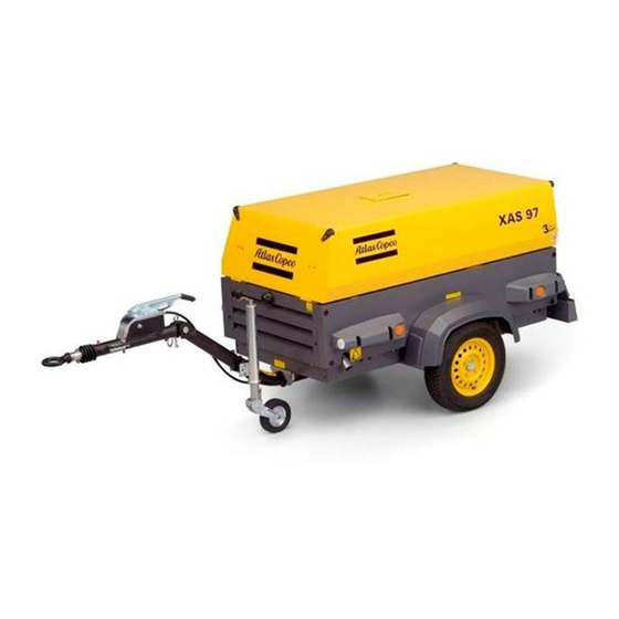
Дизельный компрессор XAS 97 — это универсальный источник сжатого воздуха, который отлично подойдет для питания различного пневматического инструмента. Пользователи этих машин ценят простое управление, надежную и проверенную десятилетиями конструкцию.
| Технические характеристики | |
|---|---|
| Рабочее давление, бар | 7 |
| Производительность, м3/мин | 5,3 |
| Количество ступеней сжатия, шт. | 1 |
| Емкость масляной системы, л | 8 |
| Вынос масла на 100 % мощности, мг/ч | <5 |
| Мощность шума по 2000/14 ЕС, дБ(А) | 98 |
| Шумовое давление на расстоянии 7 м (по ISO 2151), дБ(А) | 72 |
| Количество постов 3/4», шт. | 3 |
| Количество постов большого диаметра, шт. | — |
| Максимальная температура окружающей среды, °C | 45 °C |
| Производитель двигателя | Deutz |
| Модель | D2011L03 |
| Нормы по выхлопу | Tier III |
| Число цилиндров, шт. | 3 |
| Мощность, кВт | 36 |
| Число оборотов максимум, об./мин | 2 750 |
| Число оборотов минимум, об./мин | 1850 |
| Расход топлива на максимальной мощности, кг/ч | 8,1 |
| Расход топлива на холостом ходу, кг/ч | 3,6 |
| Тип системы охлаждения | масляная |
| Емкость системы охлаждения, л | — |
| Емкость масляной системы, л | 8,5 |
| Емкость топливного бака, л | 80 |
| Длина без шасси, мм | 1989 |
| Длина на шасси с регулируемым дышлом (транспортная), мм | 3641 |
| Длина на шасси с нерегулируемым дышлом, мм | 3063 |
| Ширина без шасси, мм | 1040 |
| Ширина на шасси, мм | 1410 |
| Высота без шасси, мм | 970 |
| Высота на шасси, мм | 1258 |
| Высота на опорах (салазках), мм | 1230 |
| Вес рабочий без шасси, кг | 850 |
| Вес рабочий с шасси, кг | 1060 |
| Производительность, м3/мин | 3-6 |
Preface
Please read the following instructions carefully
before starting to use your compressor.
It is a solid, safe and reliable machine, built
according to the latest technology. Follow the
instructions in this booklet and we guarantee you
years of troublefree operation.
Always keep the manual available near the machine.
In
all
correspondence
always
compressor type and serial number, shown on the
data plate.
The company reserves the right to make changes
without prior notice.
1
1.1
Introduction ………………………………………….. 5
1.2
1.3
1.4
1.5
mention
the
1.6
1.7
2
2.1
2.2
3
Main Parts…………………………………………. 14
3.1
3.1.1
Overview………………………………………… 16
3.1.2
Air flow………………………………………….. 18
3.1.3
Oil system ………………………………………. 19
3.1.4
3.2
Electric system ……………………………………. 22
3.3
4
4.1
4.1.1
4.1.2
4.1.3
4.1.4
4.1.5
4.1.6
— 3 —
4.2
4.3
Before starting…………………………………….. 32
4.3.1
4.3.2
4.3.3
4.3.4
5
Maintenance ……………………………………… 35
5.1
5.2
5.3
5.4
5.4.1
5.5
Oil level check ……………………………………. 40
5.5.1
5.5.2
5.6
5.6.1
5.6.2
5.7
5.8
5.9
Battery care ………………………………………… 43
5.9.1
Electrolyte………………………………………. 43
5.9.2
5.9.3
5.9.4
5.10
Changing tyres ……………………………………. 44
5.11
Storage ………………………………………………. 44
5.12
Service paks ……………………………………….. 44
5.13
Service kits…………………………………………. 44
5.14
5.15
Liability……………………………………………… 44